Additional feature
Describes the additional features of FPMS, such as work groups, licenses, account/session add-on features, access control, network topology, daily analysis·synchronization, excessive permission policy analysis, and unused object analysis.
Manage Work Groups
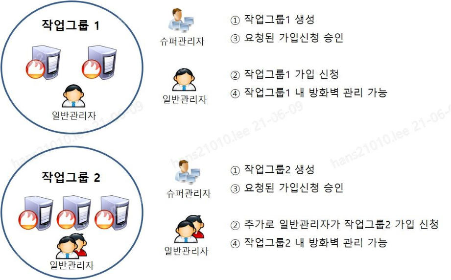
A work group is the basic unit of firewall operation tasks. Administrators are granted permission to manage only the firewalls belonging to their own work group (process application rules, search applied rules, etc.). Creating a work group based on the operational firewalls makes management easier.
Create Work Group
When a work group is created, the administrator who created it and all system administrators are automatically added.
Click Management > Work Group.
Click Create on the “Job Group” page.
Enter the following items on the “Create Work Group” page.
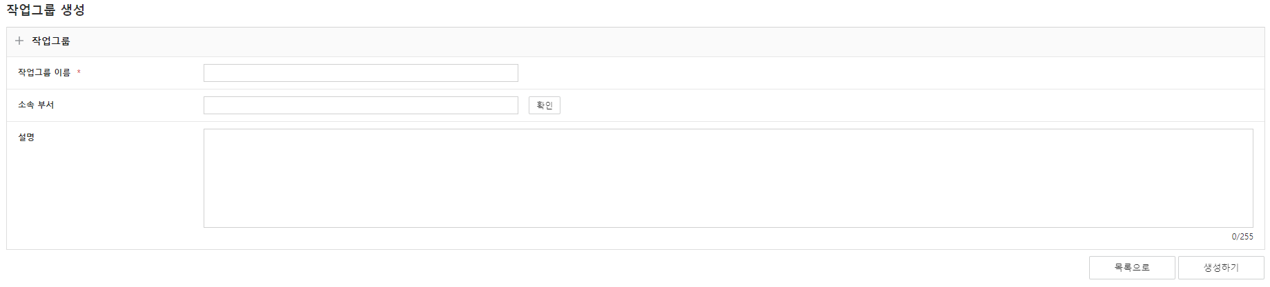
Figure. Create Work Group Item content Required/Optional Task group name Enter between 2 and 30 characters. Special characters are not allowed (except . _ - + @ ( )). Duplicate names are not allowed. Required Department By entering the affiliated department in the work group, you can link the department and work group. (Based on ESB integration) Selection Explanation Enter up to 255 characters. Selection Table. Work group input itemsClick Create.
Edit Work Group
You can change the name of the work group or its affiliated department. When a work group is modified, it does not affect the associated firewalls or administrators.
- Click Management > Work Group.
- Click the work group you want to edit.
- Click Edit on the “Job Group Details” page.
- Enter the content to edit and click Edit.
Approve work group join request
Approve the membership request for the work group. Approved administrators can manage firewalls within the work group.
Approve in Work Group
Click Management > Work Group.
Click the work group that has a join request.
Click the administrator with a pending join request status in the admin list on the “Work Group Details” page.
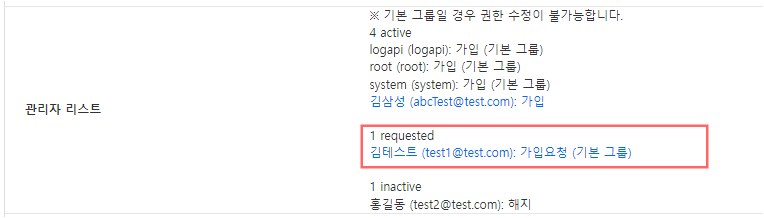
Figure. Approve membership in the work group On the “Edit Work Group Membership” page, change the work group status to ‘Join’ and click Save.
Approve as admin
Click Management > Administrator.
Click the approval target administrator.
Click the work group with a pending join request in the work group join list on the “Admin Details” page.

Figure. Admin registration approval On the “Edit Work Group Membership” page, change the work group status to ‘Joined’ and click Save.
Leave workgroup
Change the administrator’s work group membership status to terminated. A revoked administrator loses all permissions for that work group.
Cancel in Work Group: Administration > Work Group > Click the work group to be canceled > Click the administrator to be canceled in the administrator list > Change the work group status to ‘Canceled’ > Save
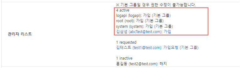
Cancel via Administrator: Manage > Administrator > Click the administrator to be cancelled > In the work group membership list, click the work group to be cancelled > Change the work group status to ‘Cancelled’ > Save

Delete Workgroup
Delete the work group, its firewalls, and related data. Work group deletion is only allowed for system administrators.
- Click Management > Work Group.
- Click the work group to be deleted.
- Click Delete > OK on the “Work Group Details” page.
License Settings
After the initial three months of use, you must register a license to use firewall policy/object synchronization and application, as well as the rule analysis feature.
- Click Management > Node System.
- Click the Default node system and click License in the left menu.
- After clicking the Create button, enter the issued license information.
- In the Default node system items, the “Applied Firewall” entry indicates the number of firewalls (Active/Standby) registered in the system.

Configuring add-on features
You can configure settings for additional features such as account information and web session management.
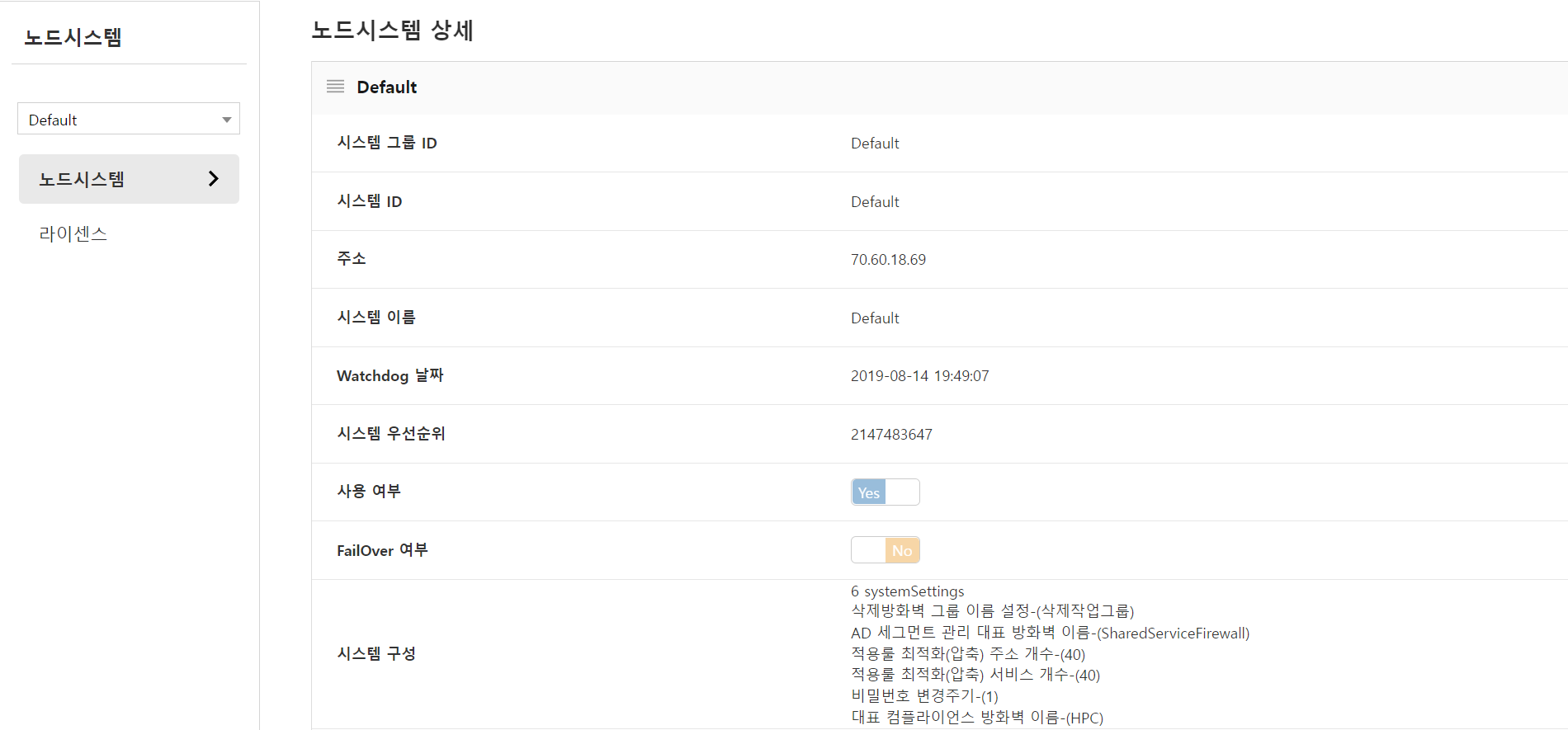
- Click Management > Node System.
- Click the Default node system.
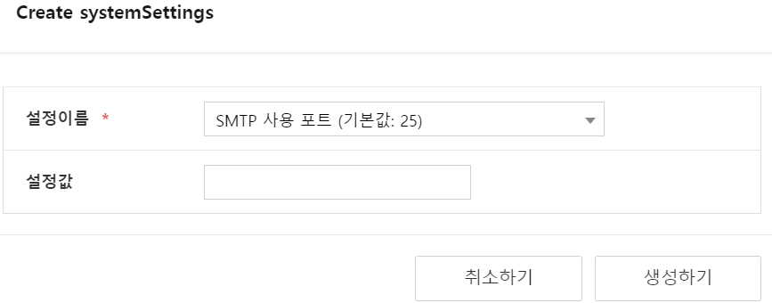
- On the “Edit” page, click CREATE SYSTEMSETTINGS in system configuration.
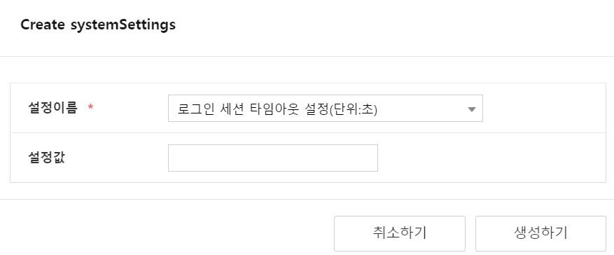
Login session timeout
You can set the session duration after login (in seconds).

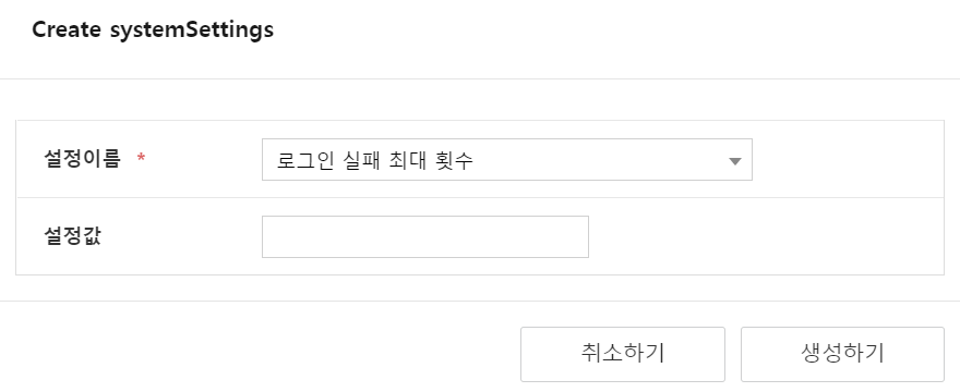
Maximum login attempts
You can set the maximum number of login attempts.
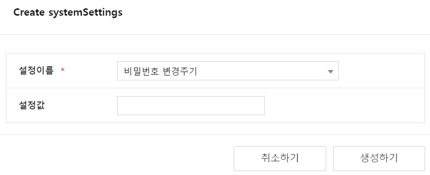
Password change cycle setting
You can set the account password change interval (default 3 months, number of months). If the allowed number of days has passed, you will be redirected to the password change page.
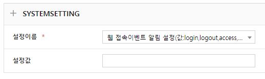
Web access event notification settings
You can set notifications for each web access type (login, logout, view (Access), edit (Audit)).
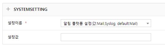
Change notification method settings
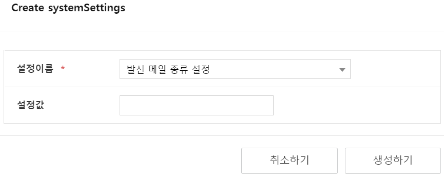
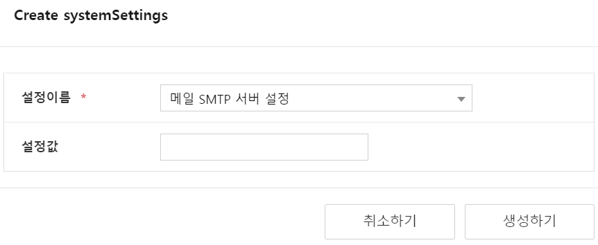
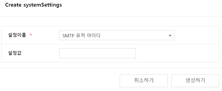
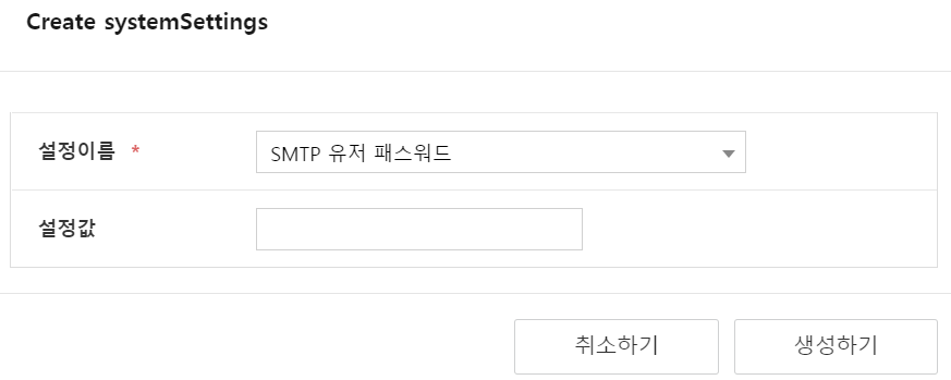
You can configure notifications using SMTP mail or syslog.
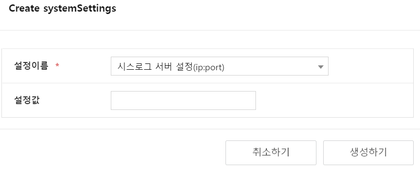
Syslog: When a firewall policy change occurs, it is sent to the configured syslog server.
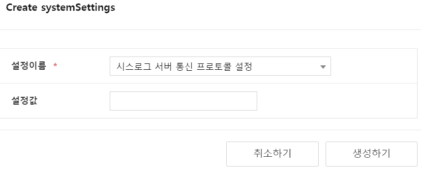
Mail Server: It can be sent to the configured SMTP mail server when a policy enforcement notification occurs. (The outgoing mail type setting value is stored as smtpMailSender)
Managing Access Control
Configure all accounts accessing from a specific IP range to have READ ONLY permissions only. Even with the same user account, it is useful when you must connect and work only in a specific server room, or when you need to grant only READ permission for external access.
Register Access Control Range
Management > Access ControlClick.
Click Create on the “Access Control” page.
Enter the following items on the “Create Access Restriction” page.

Figure. Access Restriction Creation Item content Required/Optional Band name Please enter between 2 and 30 characters. Duplicate names are not allowed. Required Alias IP range for access control required Enable connection restriction When enabled, access from the specified IP range will be changed to READ permission and logged in, even if WRITE permission is present. required Table. Access control input itemsClick Create.
Edit Access Control Range
- Management > Access Control click.
- Click the band name you want to edit on the “Access Control” page.
- Click Edit on the “Access Control Details” page.
- Enter the content to edit and click Edit.
Network topology
You can collect network connection information via SNMP of L3 or higher network devices, or view the network topology by domain group using firewall Zone information registered in the FPMS system. During the initial setup, a radial diagram is displayed in view form for each domain group, and the network layer configuration identical to the actual production network is edited directly by the user using the Edit function for nodes and edges.
Click Management > Topology.
Click the “Topology” button at the bottom of the “Topology” page.
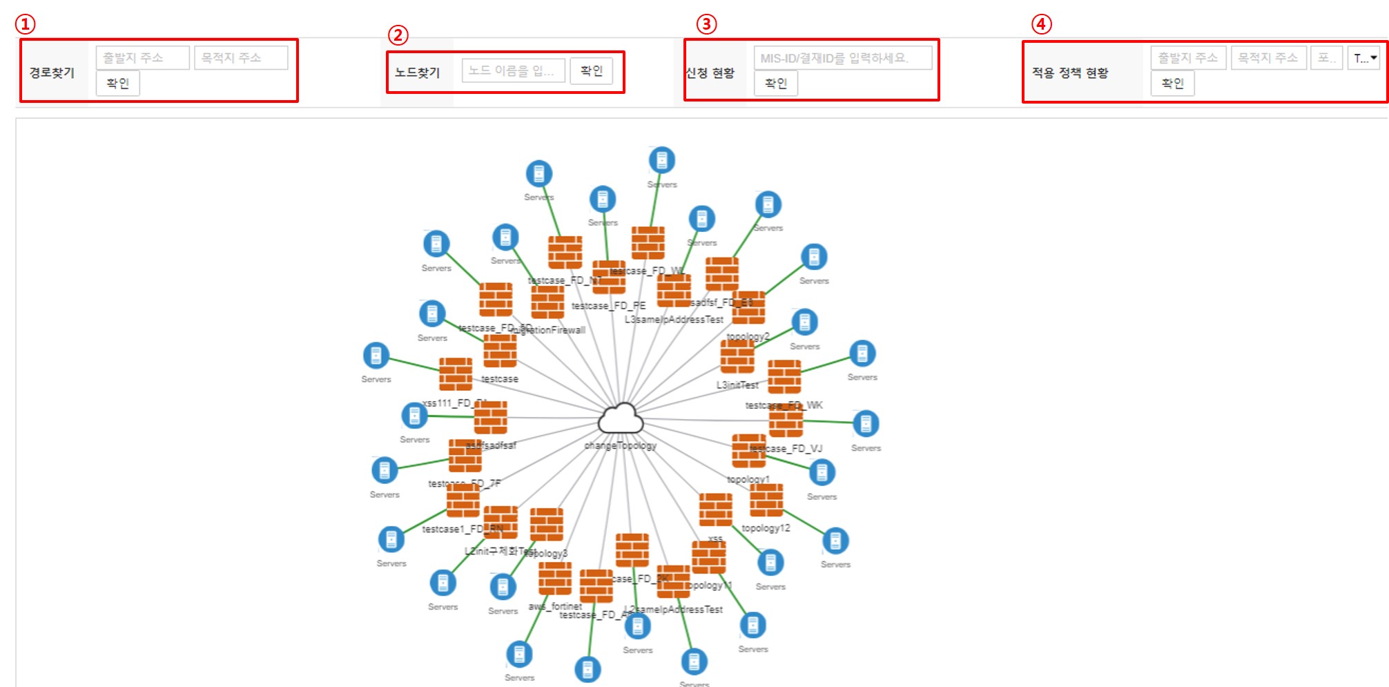
Figure. Topology
- ① Path Finding: Check segment firewall information using the source and destination addresses.
- ② Node Search: Confirm the location by searching for the firewall name.
- ③ Application Status: Verify the applied status for each segment firewall by searching the application ID.
- ④ Applied Policy Status: Check the applied firewall information by searching for source, destination, port, and protocol information.
Setting up the network topology
Domain Group Configuration: Management > Domain Group > Click the name of the domain group you want to configure > Edit > Change the Topology Collector mode to ‘Yes’ > Edit
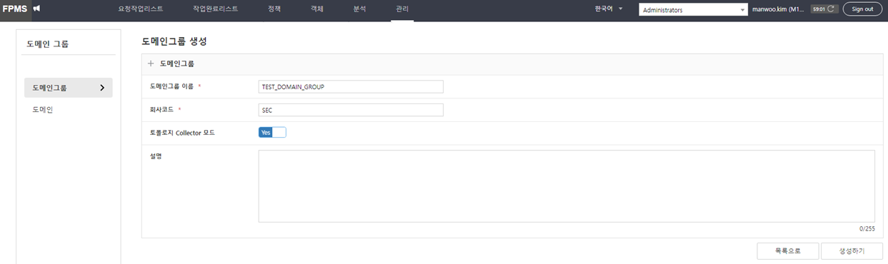
Domain Settings: Administration > Domain Groups > Left menu Domain > Click the domain you want to configure > Edit > Select the previously set domain group > Edit

Setting up manual topology collection
Firewall Domain Settings: Management > Firewall > Select target firewall for topology management > Edit > Select the previously configured domain > Edit
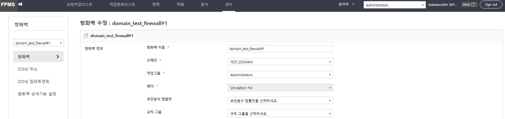
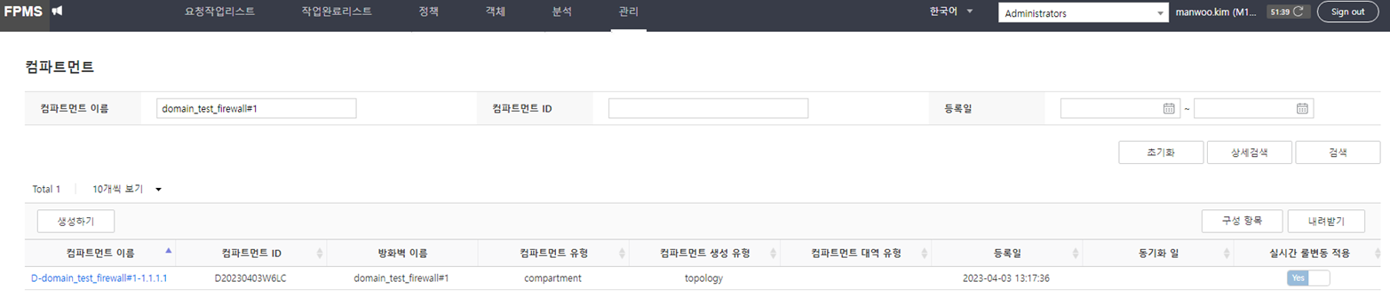
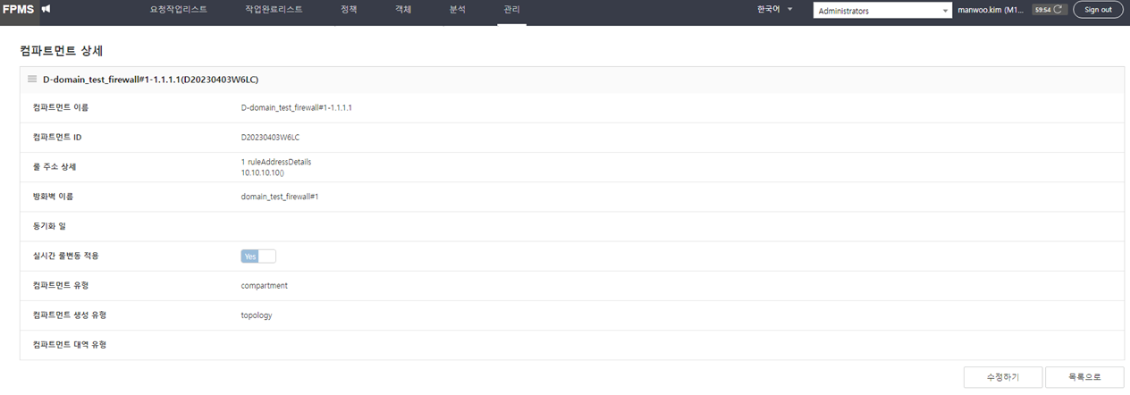
Create topology node: After executing Jenkins’s wallbrain-batch-job-topology, go to Administration > Component and verify the component whose name starts with ‘D-’.
Setting up automatic topology collection
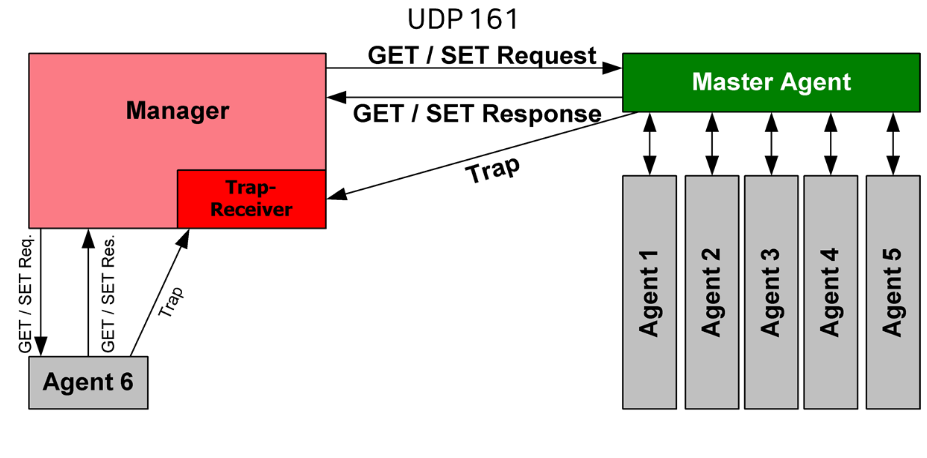
Apply for Firewall: To automatically collect firewall ranges, apply for the firewall required for SNMP communication. (FPMS → firewall, UDP 161. Target IP: firewall-integrated FPMS node system IP) Also configure the SNMP settings (community values, etc.) of the devices to be collected.
Register Collection Target Device
Click Management > Domain Group.
Click the domain group name to register the devices to be collected.
Click Edit on the “Domain Group Details” page.
Click CREATE PROVIDERS on the “Domain Group Edit” page. 4. “Create providers” popup window appears.
Please enter the following item.
Item Explanation Type firewall: L3 firewall (firewall integrated with FPMS) / network: L3 network device (router that includes the L2 firewall zone) Firewall Firewall integrated with FPMS address IP address of the collection device Port SNMP collection port number 161 Community community value Password community String(password) Table. Provider input itemsClick Create. 6. “Domain Group Edit” page’s Servers from SNMP list shows that a Provider has been added.
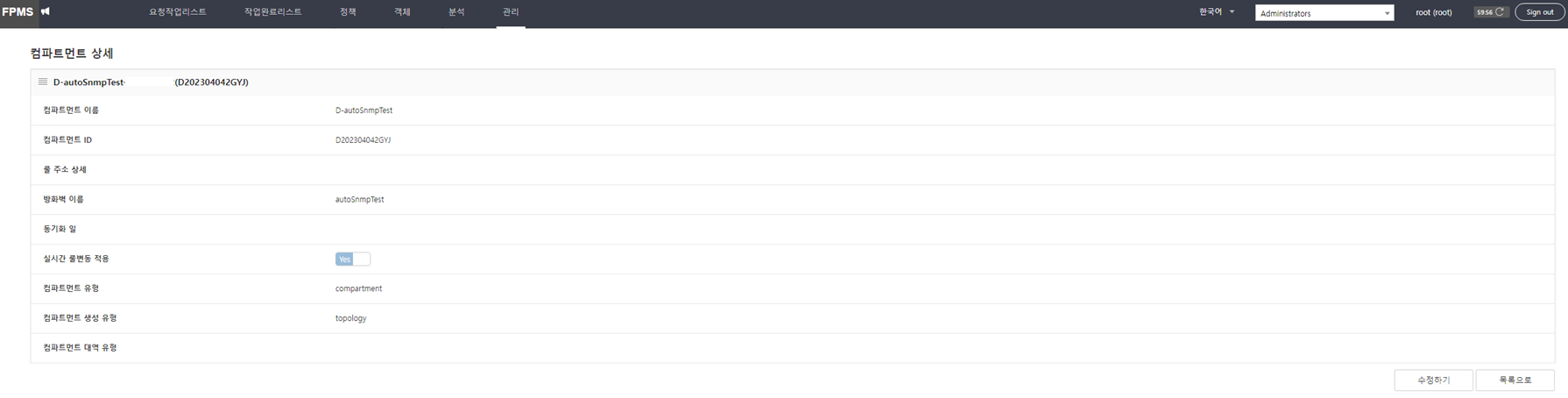
Create topology node: After running Jenkins’s wallbrain-batch-job-topology, check the compartment in Administration > Compartment whose name starts with ‘D-’.

Configuring Firewall SNMP: Refer to each vendor > Configuring Firewall SNMP in the 「Firewall Vendor Configuration Guide」. (Secui MF2, Secui Bluemax, Fortinet, Paloalto, Ahnlab, Axgate, Checkpoint, Cisco, Juniper support)
Using the Topology View feature
Configure Topology View: Management > Topology > Click the “Topology” button in the lower right > Click Edit in the lower left of the Topology View area
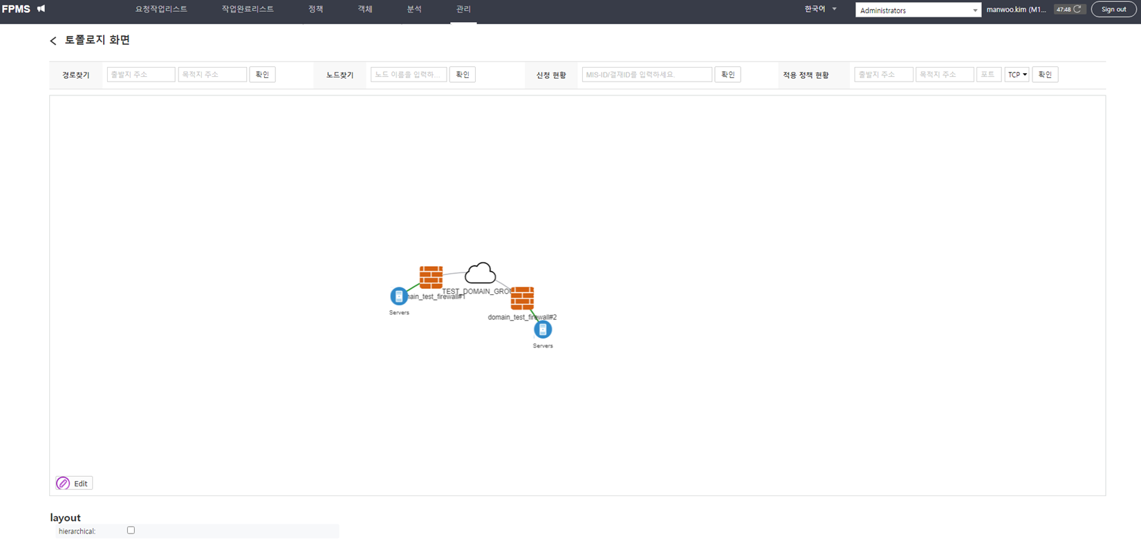
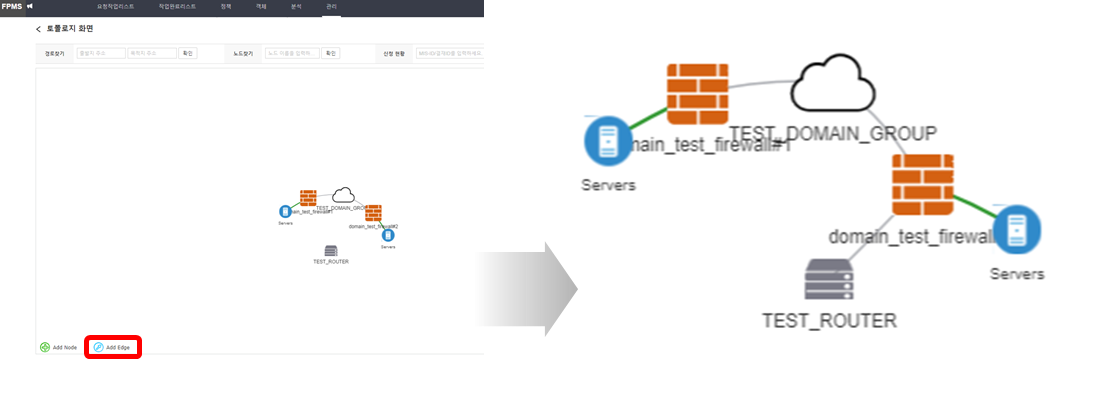
Edit Edge: Select the edge (Edge) you want to modify, click Edit Edge, then drag the edge to the top firewall node to connect it and draw the line.
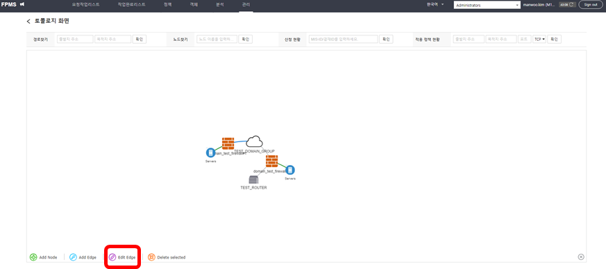
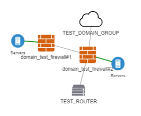
Delete Node and Edge (Edge): After selecting the node or edge (Edge) to delete, click Delete Edge.
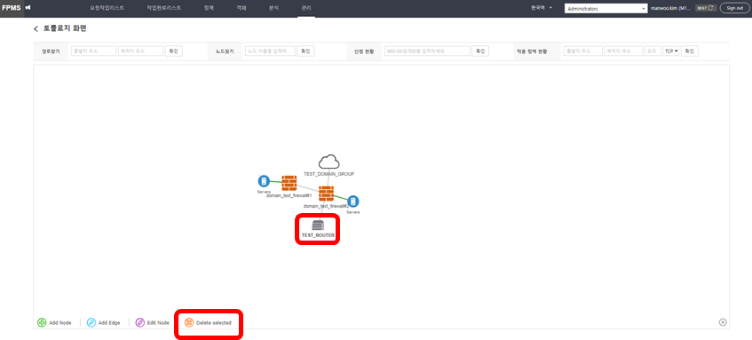
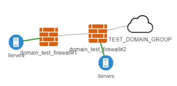
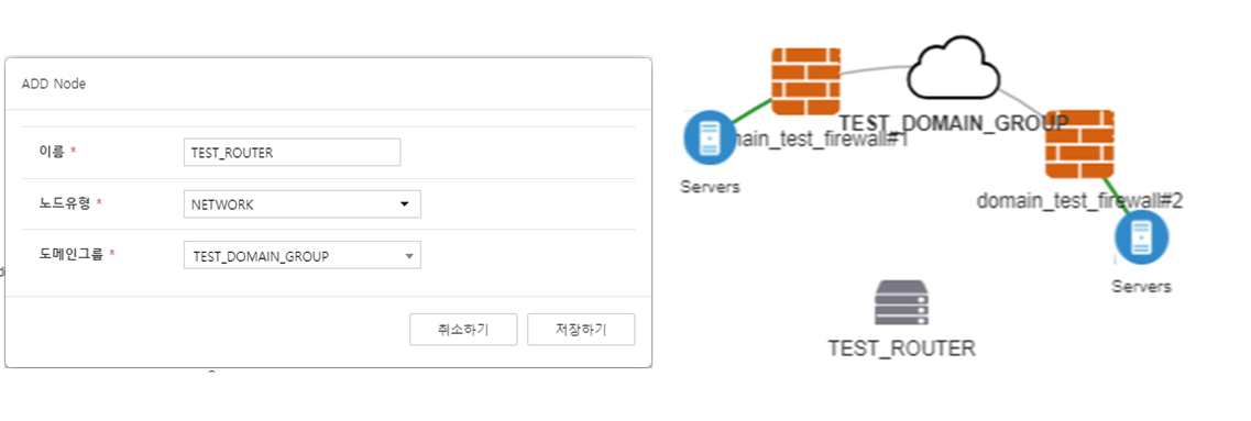
Add Node: Click Add Node at the lower left, enter the node information, and then connect the added node.
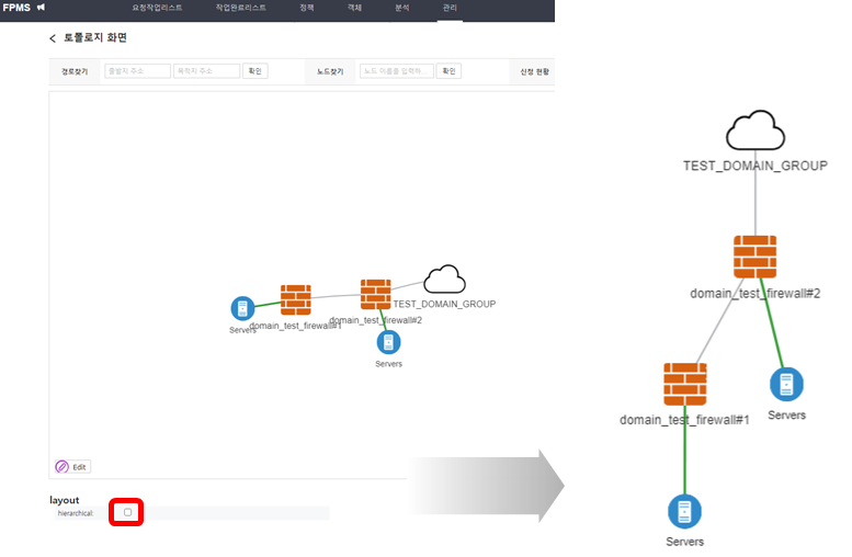
View in Hierarchical Structure (Hierarchical View): Click the hierarchical checkbox in the layout at the lower left.
Using the shared group object firewall feature
Set up a firewall that manages shared group objects, allowing you to manage and use address group objects that must be used consistently across all firewalls registered in FPMS.
Configure shared group object options
In Management > Firewall, create a firewall for managing shared group objects. 1. (Vendor is set to simulation FW)
After selecting Management > Node System > Default, click Edit.
In the system configuration, select “Shared Group Object Management Representative Firewall Name” and then enter the firewall name for shared group object management.
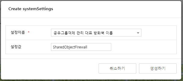
Figure. Shared Group Object Options Configuration Click Create. 4. The generated option can be viewed in the node system Default.
Using the Representative Firewall Feature for AD Segment Management
This feature allows you to input an address group object when creating an AD user or group policy, enabling you to reference and use the firewall’s group objects to create policies.
Setting AD Segment Management Options
In Management > Firewall, create a firewall for AD segment management. 1. (Vendor is set to simulation FW)
Select Management > Node System > Default, then click Edit.
In system configuration, select “AD Segment Management Representative Firewall Name” and then enter the AD Segment Management Representative Firewall Name.
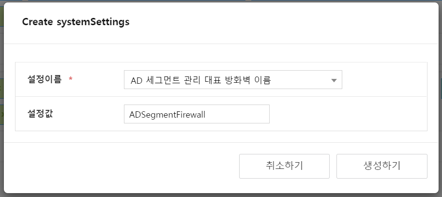
Figure. AD Segment Management Options Settings Click Create. 4. The generated option can be viewed in the node system Default.
Daily, Using Comparative Analysis Between Policies
Provides the ability to perform security analysis periodically.
- Daily analysis: It is performed periodically only for analyses that do not involve comparisons between policies such as duplicate rules and shadow. - (Set interval in days, default 1)
- Policy comparison analysis: It is performed periodically only for analyses that require comparisons between policies, such as duplicate rules, shadowing, etc. - (Set interval in weeks, default 4)
Set daily analysis options
Click Management > Node System > Default > Left System Configuration.
Click Create, then select “Perform daily analysis” and enter the value true.
To run on a cycle other than the default provided cycle, select “Daily Analysis Cycle” and then enter a value that matches the unit.
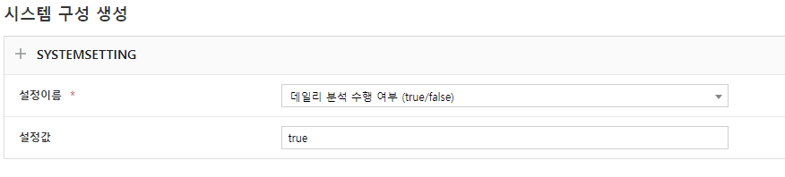
Figure. Daily Analysis Options Settings 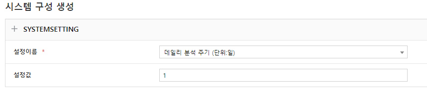
Figure. Daily analysis option setting Click Create.
- Analyses generated by performing daily analysis have job IDs that start with “DA”.
- Daily analysis does not support duplicate rules, Shadow, or partial Shadow, which are comparative analyses between policies.
Set comparison analysis options between policies
Click Management > Node System > Default > Left System Configuration.
Click Create, then select “whether to perform comparative analysis between policies” and input the value true.
To run on a cycle other than the default provided cycle, select “Policy Comparison Analysis Cycle” and enter a value appropriate to the unit.
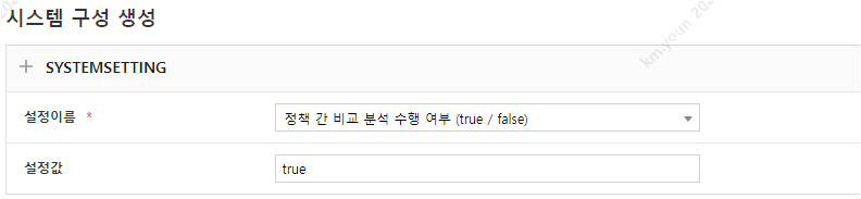
Figure. Policy comparison analysis options setting 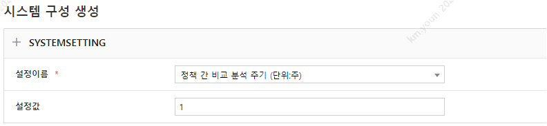
Figure. Policy comparison analysis options configuration Click Create. 4. (Analyses generated through comparative analysis between policies have job IDs that start with “CA”.)
Using Daily Policy Sync
Provides the ability to perform policy synchronization periodically. (Daily synchronization: Periodically synchronize firewall device objects and policy contents to FPMS. Set the interval in days, default value 1)
Configure Daily Policy Sync Option
Click Management > Node System > Default > Left System Configuration.
After clicking Create, select “Perform Daily Policy Sync” and set the value to true.
To perform on a cycle other than the default provided, select “Daily policy synchronization cycle” and enter a value appropriate to the unit.
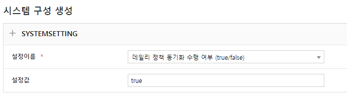
Figure. Daily policy synchronization option settings 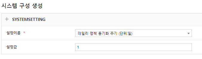
Figure. Daily Policy Sync Option Settings Click Create.
Over-Permission Policy Analysis
Analyze the log files of the over‑allowance policy, then create a file or generate a ruleset.
Configure Over-Permission Policy Analysis Options
Create a “log analysis firewall” for log analysis. 1. (Created as Simulation FW vendor)
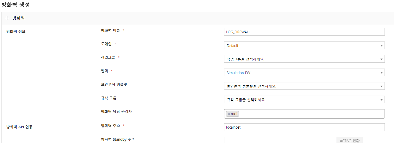
Figure. Create firewall for log analysis Click Management > Node System > Default > Left System Configuration.
Click Create, then select “Representative Log Analysis Firewall” and enter the name of the created log analysis firewall.

Figure. Representative log analysis firewall configuration Create policy rule groups, policy rules, etc., to set up policy rules for log analysis conversion. 4. (Depending on the situation RULE rule — when a policy change is needed, policy separation rule — setting when policy separation is required)
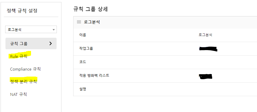
Figure. Policy rule settings for log analysis conversion If you performed step 4, you need to configure the rule group in Management > Firewall > Firewall for Log Analysis.
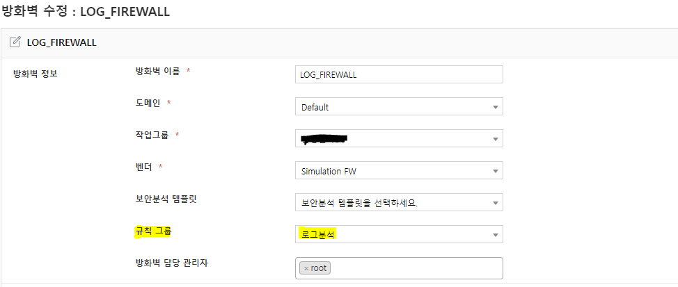
Figure. Firewall rule group settings for log analysis Execute the LOG convert command in the provided Jenkins cmd.
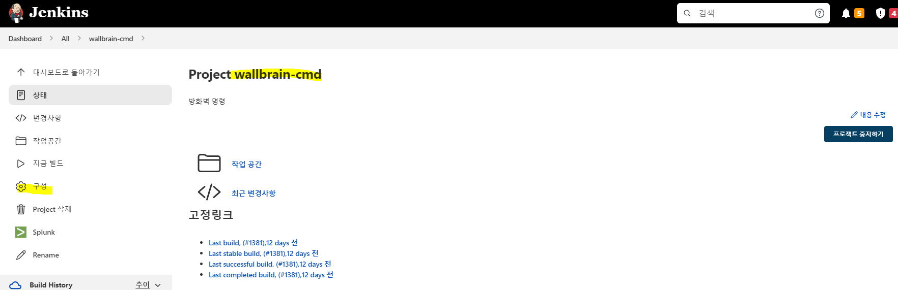
Figure. LOG convert execution
log-convert command example
RUN_CMD="-c log-convert -f {경로}/ff.csv -s rr -t dst,svc -u NG_OCAM"
RUN_CMD="-c log-convert -f {경로}/ff.csv -s rs -t dst,svc -u NG_OCAM -a t -d 정책ID -i 방화벽이름"
Option description
- f: file name
- t: Items to include in the analysis among source/destination/service (if omitted, all are analyzed, e.g., -t src,dst)
- O: (When using Rule) If there is no mapped group object, default group object name
- u: (when using a split rule) If there is no mapping rule, default split keyword
- s: Analysis result export method rr/fr/rs (rr: request rule bundle file, fr: firewall policy bundle file, rs: FPMS rule set generation, multiple supported separated by commas)
- d: Policy ID for inserting the analysis result above a specific location when the s option is set to rs
- i: d option’s firewall name with policy ID (when export mode is rs, the rule set is created on that firewall; default: primary log firewall)
- a: Option to generate with requesting when rule set creation takes a long time (t: requesting / f: requested)
Unused Object Analysis
This function determines whether firewall objects (Address/Service/AddressGroup/ServiceGroup) are unused and returns the results in Excel.
- To perform the analysis, the firewall must be integrated with the log analysis system.
- Logs from a redundant firewall (when the log server has two logServerKey values) are aggregated and analyzed.
- The Address type supports only CIDR-based objects.
- Objects with duplicate names according to the FPMS DB are excluded from the analysis.
Analysis of Unused Objects by Firewall
API-based: Execute the object-unused-check command in the provided Jenkins cmd. The job results can be viewed in the Jenkins workspace.

object-unused-check command example
RUN_CMD="-c object-unused-check -i 방화벽이름 -O 90"
RUN_CMD="-c object-unused-check -i 방화벽이름 -O 90 -t 1 -s 2417"
Option description
- i: Firewall name (required)
- O: Valid period (days) of logs to analyze, only logs within that date range are analyzed (default 90 days if not entered)
- t: When analyzing per rule, start index (if t, s are not provided, execute all rules)
- s: When analyzing by rule unit, end index
- a: When calling the log API, Page size (if not entered, 100,000 items)
File-based: Extract the firewall’s flow/archive logs to be analyzed from the log server using a script, upload them to FPMS, and then execute the object-unused-check-file command in the provided Jenkins cmd.

object-unused-check-file command example
RUN_CMD="-c object-unused-check-file -i 방화벽이름 -f flow_0.csv,flow_1.csv -d archive_0.csv,archive1.csv -t file -d true -s true"
RUN_CMD="-c object-unused-check-file -i 방화벽이름 -d archive_0.csv,archive_1.csv -t api -O 90"
Option description
- i: Firewall name (required)
- f: flow file name (comma-separated, without spaces)
- d: archive file name (comma-separated, without spaces)
- t: flow analysis type (api/file)
- s: Perform single-file unit when analyzing archive files (true/false)
- O: Validity period of logs to be analyzed (days) (default 90 days if not entered)
- a: When calling the log API, Page size (if not entered, 100,000 entries)
Analysis of Unused Status by Firewall Object
Execute the object-unused-check-input command in the provided Jenkins cmd. The job results can be viewed in the Jenkins workspace.

object-unused-check-input command example
RUN_CMD="-c object-unused-check-input -i 방화벽이름 -t address -s 객체1,객체2,객체3 -O 90"
RUN_CMD="-c object-unused-check-input -i 방화벽이름 -t addressGroup -s 그룹객체1,그룹객체2 -O 90"
RUN_CMD="-c object-unused-check-input -i 방화벽이름 -t service -s object_all -O 90"
Option description
- i: Firewall name (required)
- O: Validity period of logs to be analyzed (days) (default 90 days if not entered)
- t: Object to be analyzed Type (select from address/addressGroup/service/serviceGroup, required)
- s: List of object names to analyze (comma-separated, without spaces / “object_all” input selects the entire type, required)
- a: When calling the log API, Page size (if not entered, 100,000 entries)