Users can create the service by entering the required information for a Bare Metal Server and selecting detailed options through the Samsung Cloud Platform Console.
Create Bare Metal Server
You can create and use the Bare Metal Server service from the Samsung Cloud Platform Console.
To create a Bare Metal Server, follow these steps.
- All Services > Compute > Bare Metal Server Click the menu. 1. Go to the Service Home page of the Bare Metal Server.
- On the Service Home page, click the Create Bare Metal Server button. 2. Go to the Bare Metal Server Creation page.
- Bare Metal Server Creation page, enter the information required to create the service and select detailed options.
- Select the required information in the Image and version selection area.
Category required statusDetailed description Image Required Select the type of Image provided - RHEL, Rocky Linux, Ubuntu, Windows
- Refer to the caution information below for the server types available for each OS Image
Image version Required Select version of the selected Image - Provide a version list of the provided server Image
Table. Bare Metal Server Image and version input itemsCautionThe server types that can be requested vary by OS image as follows.
OS Image version s4/h4 server type s3/h3 server type s2/h2 server type Oracle Linux 9.6 O O O RHEL 8.10 X O O RHEL 9.4 O O O RHEL 9.6 O O O Rocky Linux 8.10 X O O Rocky Linux 9.6 O O O Ubuntu 22.04 Confirmation needed O O Ubuntu 24.04 O O Confirmation needed Windows 2019 X O O Windows 2022 O O O - s3/h3, s2/h2 server types are no longer accepting new service applications. * There is no impact on the services currently in use.
- For Ubuntu, the server types you can request may vary depending on resource availability. * Please confirm before applying for the service.
- Enter or select the required information in the Service Information Input area.
Category required statusDetailed description Number of servers Required Number of Bare Metal Servers to create simultaneously - Only numeric input is allowed, and up to 20 servers of the same type can be created simultaneously
Service Type > Server Type Required Bare Metal Server server type - Select the desired vCPU, Memory, and Disk specifications
- For detailed information about the server types provided by Bare Metal Server, refer to Bare Metal Server 서버 타입
Service Type > Planned Compute Required Status of resources with Planned Compute configured - In Use: Number of resources with Planned Compute that are currently in use
- Configured: Number of resources with Planned Compute configured
- Coverage Preview: Amount applied per resource by Planned Compute
- Create Planned Compute Service: Go to the Planned Compute application page
- For more details, see Planned Compute 신청하기
Table. Bare Metal Server Service Information Input Items - In the Required Information Input area, enter or select the required information.
Category required statusDetailed description Administrator account Required Set the administrator account and password to be used when connecting to the server - RHEL and Ubuntu OS are provided with a fixed root account
- For Windows OS, enter 5 to 20 characters using lowercase letters and numbers
AdministratorNot allowed
Server name Required When the selected number of servers is 1, enter a name to distinguish the Bare Metal Server - It must start with a lowercase English letter and be entered using lowercase letters, numbers, and special characters (
-) within 3 to 15 characters
- It must not end with a special character (
-)
- Set the hostname to the entered server name
Server name (auto-generated number) Required It is enabled when the number of selected servers is 2 or more, and you must enter a name for distinguishing the Bare Metal Server in the format name-###(e.g., test-001)- It must start with a lowercase English letter and be entered using lowercase letters, numbers, and special characters (
-) within 3 to 15 characters
- It must not end with a special character (
-)
- Set the hostname to the entered server name
- Automatically generate by incrementing from the entered number by 1 (excluding numbers already in use)
Network Settings Required Set the network where the Bare Metal Server will be installed - Select a pre-created VPC
- General Subnet: Select a pre-created general Subnet
- IP can be auto-generated or user-provided, and if input is selected, the user enters the IP manually
- NAT: Available only when there is one server and the VPC is connected to an Internet Gateway
- When checked, a NAT IP can be selected
- NAT IP: Select a NAT IP
- If no NAT IP is available to select, click the Create New button to generate a Public IP
- Click the Refresh button to view and select the generated Public IP
- Creating a Public IP incurs charges according to the Public IP pricing policy
- Local Subnet (optional): Choose to use a local Subnet
- It is not a required element for creating the service
- Select a pre-created local Subnet
- IP can be auto-generated or user-provided, and if input is selected, the user enters the IP manually
Table. Bare Metal Server required information entry items
- Select the required information in the Image and version selection area.
Please use a firewall, etc., to control traffic access for the Bare Metal Server. Security Group is not provided.
The firewall of a Bare Metal Server can only be used to control traffic between the Bare Metal Server and Virtual Server. To use the Firewall of a Bare Metal Server, follow the steps below.
- Separate the VPC of Bare Metal Server: Separate them so that the Bare Metal Server and Virtual Server do not use the same VPC.
- Transit Gateway Creation: Create a Transit Gateway.
- The integration between the VPC of a Virtual Server and the VPC of a Bare Metal Server uses a Transit Gateway.
- When creating a Transit Gateway integration in the VPC of a Bare Metal Server, you must also create the Bare Metal Server’s firewall.
- Firewall Rule Registration: Register the rule in the Firewall of the Bare Metal Server.
On the Bare Metal Server Creation page, in the Additional Information Input area, enter or select the required information.
Category required statusDetailed description Local disk partition Selection Set whether to use the local disk partition - Up to 10 partitions can be created, including the root partition
- Can use up to 90% of the total capacity
- After checking Use, you can configure partition information
- Configure root partition information
- Partition type: flat, lvm selectable
- Partition name: enter partition name
- Can be entered only when partition type is lvm
- Enter up to 15 characters starting with a letter and containing letters, numbers, and special characters (
-_)
- Partition size: enter at least 50 GB
- Filesystem type: select according to the used image
- For RHEL, Rocky Linux: xfs, ext4
- For Ubuntu: ext4, xfs, btrfs
- For SLES: btrfs, xfs, ext4
- Mount point: start with special character
/and include letters, numbers, and special characters (-_) up to 15 characters- Cannot be entered when Filesystem type is swap
- Available capacity: 90% of the default disk capacity provided when selecting a server
- When setting partition size, the remaining capacity is automatically calculated and displayed
- The total partition disk size cannot exceed the available capacity
- Configure additional partition information
- Partition type: flat, lvm selectable
- Partition name: enter partition name
- Partition type can be entered only when it is lvm
- Enter up to 15 characters starting with a letter and containing letters, numbers, and special characters (
-_) up to 15 characters
- Partition size: enter at least 1 GB
- Filesystem type: select according to the used image>
- For RHEL, Rocky Linux: xfs, ext4, swap
- For Ubuntu: ext4, xfs, btrfs, swap
- For SLES: btrfs, xfs, ext4, swap
- Mount point: start with special character
/and include letters, numbers, and special characters (-_) up to 15 characters- Cannot be entered when Filesystem type is swap
- Available capacity: 90% of the default disk capacity provided when selecting a server
- When setting partition size, the remaining capacity is automatically calculated and displayed
- The total partition disk size cannot exceed the available capacity
Placement Group Selection Servers belonging to the same Placement group are distributed across different racks - Provides distributed placement for up to two servers belonging to the same Placement group
- For distributed placement of three or more servers, add additional Placement groups
- Applicable only at initial creation and cannot be modified afterward
- If you terminate the last server in a Placement group, that Placement group is automatically deleted
Lock Selection Using a lock prevents actions caused by mistakes, such as terminating, starting, or stopping the server. Init Script Selection Script to run when the server starts - The Init Script must be selected differently depending on the Image type
- For Windows: Select Batch Script
- For Linux: Shell Script
Table. Bare Metal Server Additional Information Input ItemsSummary Check the detailed information and estimated charges generated in the panel, and click the Create button.
- Once creation is complete, check the created resources on the Bare Metal Server List page.
Check detailed information of Bare Metal Server
The Bare Metal Server service allows you to view and edit the complete resource list and detailed information. The Bare Metal Server Details page consists of Details, Tags, Activity History tabs.
To view detailed information about the Bare Metal Server, follow these steps.
- All Services > Compute > Bare Metal Server Click the menu. 1. Go to the Service Home page of the Bare Metal Server.
- On the Service Home page, click the Bare Metal Server menu. 2. Go to the Bare Metal Server List page.
- On the Bare Metal Server List page, click the resource to view detailed information. 3. Go to the Bare Metal Server Details page.
- Bare Metal Server Details page displays status information and additional feature information, and consists of Details, Tags, Operation History tabs.
Category Detailed description Bare Metal Server status Status of the Bare Metal Server created by the user - Creating: State while the server is being created
- Running:: State when creation is complete and the server is usable
- Editing:: State while the IP is being changed
- Unknown: Error state
- Starting: State while the server is starting
- Stopping: State while the server is stopping
- Stopped: State when the server has stopped
- Terminating: State while terminating
- Terminated: State when termination is complete
Server operation control button Button to change server status - Start: Start a stopped server
- Stop: Stop a running server
Service cancellation Cancel service button Table. Bare Metal Server status information and additional functions
- Bare Metal Server Details page displays status information and additional feature information, and consists of Details, Tags, Operation History tabs.
Detailed Information
On the Bare Metal Server List page, you can view the detailed information of the selected resource and, if needed, modify the information.
| Category | Detailed description |
|---|---|
| service | service name |
| Resource Type | Resource Type |
| SRN | Unique resource ID in Samsung Cloud Platform
|
| Resource name | Resource name
|
| Resource ID | Unique resource ID in the service |
| Constructor | User who created the service |
| Creation date and time | Service creation date and time |
| Modifier | User who edited the service information |
| Modification date and time | Date and time the service information was modified |
| Server name | server name |
| Image/Version | Server OS image and version |
| Server type | Display vCPU and memory information |
| Planned Compute | Resource status with Planned Compute configured
|
| Lock | Indicates whether Lock is enabled/disabled
|
| CPU settings | When configuring the CPU, CPU specification information and current status
|
| Placement Group | Placement Group name |
| Network | Network information of the Bare Metal Server
|
| Local Subnet | Local Subnet information of the Bare Metal Server
|
| Block Storage | Block Storage information connected to the server
|
| Init Script | View the Init Script content entered during server creation |
Tag
Bare Metal Server list page lets you view the tag information of the selected resource, and you can add, modify, or delete it.
| Category | Detailed description |
|---|---|
| Tag list | Tag list
|
Job History
Bare Metal Server List page allows you to view the operation history of the selected resource.
| Category | Detailed description |
|---|---|
| Task History List | Resource change history
|
Bare Metal Server Resource Management
If you need server control and management functions for the created Bare Metal Server resources, you can perform tasks on the Bare Metal Server List or Bare Metal Server Details page.
Bare Metal Server Control Operation
You can start, stop, and restart a running Bare Metal Server.
- When a Bare Metal Server is stopped, the server’s power is turned off.
- Since stopping may affect applications or storage in use, it is recommended to shut down the OS before stopping the Bare Metal Server.
- After shutting down the OS, be sure to also stop the console.
To control the operation of a Bare Metal Server, follow these steps.
- All Services > Compute > Bare Metal Server Click the menu. 1. Go to the Service Home page of the Bare Metal Server.
- On the Service Home page, click the Bare Metal Server menu. 2. Go to the Bare Metal Server List page.
- Bare Metal Server List page, after selecting multiple servers, you can control multiple servers simultaneously using the Start and Stop buttons at the top of the table.
- Bare Metal Server Details The page also allows you to start and stop the server.
- On the Bare Metal Server List page, click the resource to control its operation and navigate to the Bare Metal Server Detail page.
- Check the server status and click the server operation control button to complete the change.
- Start: Start the stopped server.
- Stop: Stops the running server.
- If a Bare Metal Server cannot be started when a start request is made, refer to the following.
- When Lock is enabled: Change the Lock setting to disabled, then try again.
- If the Bare Metal Server’s status is not Stopped: Change the Bare Metal Server’s status to Stopped, then try again.
- If a stop request for a Bare Metal Server cannot be performed, refer to the following.
- If Lock is set: Change the Lock setting to disabled, then try again.
- If the Bare Metal Server’s status is not Running: Change the Bare Metal Server’s status to Running, then try again.
Add Block Storage
You can add Block Storage to a Bare Metal Server.
To add Block Storage, follow the steps below.
- All Services > Compute > Bare Metal Server Click the menu. 1. Go to the Service Home page of the Bare Metal Server.
- On the Service Home page, click the Bare Metal Server menu. 2. Go to the Bare Metal Server List page.
- Bare Metal Server List page, click the server to which you want to add Block Storage. 3. Go to the Bare Metal Server Details page.
- On the Bare Metal Server Details page, click the Add button in the Block Storage section.
- When the popup confirming Block Storage addition opens, click the Confirm button. 5. Block Storage (BM) Creation Navigate to the page.
- On the Block Storage(BM) Creation page, enter the information required to create the service and create a Block Storage.
- For detailed information on creating Block Storage (BM), see Block Storage(BM) 생성하기-create).
- Navigate to the Bare Metal Server Details page where Block Storage was added and confirm that Block Storage has been added.
Configure CPU
You can configure the CPU of a Bare Metal Server. To configure the CPU, follow these steps.
All Services > Compute > Bare Metal Server Click the menu. 1. Go to the Service Home page of the Bare Metal Server.
On the Service Home page, click the Bare Metal Server menu. 2. Go to the Bare Metal Server List page.
On the Bare Metal Server List page, click the resource to configure the CPU. 3. Go to the Bare Metal Server Details page.
On the Bare Metal Server Details page, click the Edit button in the CPU Settings item. 4. Edit CPU Settings A popup window opens.
After entering whether to use the CPU settings and the configuration information, click the Confirm button.
Category required statusDetailed description Use status Required Select whether to enable the CPU setting - When Use is set, Thread per core and core count are required inputs
Threads per core Required Set Hyper threading usage - To disable Hyper threading, set Thread per core to 1
Number of cores Required Set the number of vCPUs to activate - Changing the number of cores does not affect the price.
Total vCPU count - The final number of vCPUs to be activated on the server - Automatically calculate and display the value obtained by multiplying Thread per core by number of cores
Table. CPU configuration information itemsWhen the pop-up notifying CPU setting changes opens, click the Confirm button.
Check that the CPU settings have been correctly modified on the Bare Metal Server Details page.
- If you modify the CPU settings, they are reflected in the Console immediately, but they take effect on the actual server only after a reboot.
- After modifying the settings, be sure to reboot (stop/start in the console) the server directly.
- If you modify the CPU settings again before rebooting, an error occurs.
- The number of configurable cores may vary depending on the server environment.
- By default, it provides the option to select 25%, 50%, or 75% of the total cores.
- Since the number of cores that can be configured when requesting a server may vary depending on the server environment, if you need any additional settings, be sure to inquire before applying for a Bare Metal Server and then proceed with the application.
Terminate Bare Metal Server
If you terminate an unused Bare Metal Server, you can reduce operating costs. However, if you terminate a Bare Metal Server, the running service may be stopped immediately, so you should proceed with the termination only after fully considering the impact of service interruption.
To cancel a Bare Metal Server, follow the steps below.
- All Services > Compute > Bare Metal Server Click the menu. 1. Go to the Service Home page of the Bare Metal Server.
- On the Service Home page, click the Bare Metal Server menu. 2. Go to the Bare Metal Server List page.
- On the Bare Metal Server List page, select the resource to terminate, and click the Terminate Service button.
- You can select multiple resources and delete them simultaneously.
- You can also delete the resource by clicking the Cancel Service button on the Bare metal Server Details page.
- Once the termination is complete, check the Bare Metal Server List page to see if the resource has been terminated.
Termination constraints
If a Bare Metal Server termination request cannot be completed, a popup will provide guidance. Please refer to the case below.
When Block Storage(BM) is connected (simultaneous termination of two or more servers): Please disconnect the Block Storage(BM) first.
- For detailed information on how to cancel, please refer to Block Storage(BM) 해지하기.
If File Storage is connected: First, disconnect the File Storage.
- For detailed information on how to cancel, please refer to File Storage 해지하기.
If Lock is set: Change the Lock setting to disabled, then try again.
If there are resources connected to Backup Agent or Load Balancer: First disconnect the connections of those resources.
If resource management tasks for Bare Metal Server are in progress on the same account: After the Bare Metal Server resource management tasks are completed, please try again.
If the Bare Metal Server’s status is not Running or Stopped: Change the Bare Metal Server’s status to Running or Stopped, then try again.
If the selection includes a server that cannot be terminated simultaneously: Select only resources that can be terminated, then try again.
Configure local Subnet
After completing the creation of a Bare Metal Server, when adding a local Subnet on the Bare Metal Server Details page, the user must manually configure the network settings of the local Subnet.
First connection (kr-west)
If there is no local subnet connected to the Bare Metal Server and you are adding the first connection, follow the guide below.
This guide applies to kr-west(Korea West) when adding the first local Subnet connection to the server.
- The guide corresponding to kr-south(South Korea) can be found in the First connection (kr-south) chapter.
Linux - Setting up Subnet on Ubuntu
To add a local Subnet and configure the network on an Ubuntu operating system, follow these steps.
On the Bare Metal Server Details page, check the Interface Name.
Retrieve the network configuration information.
Color mode[root@localhost ~]# vi /etc/netplan/50-cloud-init.yaml network: ethernets: ens2f1: match: macaddress: 68:05:ca:d4:09:91 mtu: 1500 set-name: ens2f1 ens4f1: match: macaddress: 68:05:ca:d4:09:01 mtu: 1500 set-name: ens4f1[root@localhost ~]# vi /etc/netplan/50-cloud-init.yaml network: ethernets: ens2f1: match: macaddress: 68:05:ca:d4:09:91 mtu: 1500 set-name: ens2f1 ens4f1: match: macaddress: 68:05:ca:d4:09:01 mtu: 1500 set-name: ens4f1Code block. View network configuration file After adding a new VLAN, set the IP for the bonding configuration.
- Replace the example code’s ID and IP with the assigned ID and IP.Color mode
[root@localhost ~]# vi /etc/netplan/50-cloud-init.yaml network: bonds: bond-mgt: interfaces: - ens2f1 // **Bare Metal Server Details** Enter the Interface Name displayed on the page. - ens4f1 // **Bare Metal Server Details** Enter the Interface Name shown on the page. mtu: 1500 parameters: mii-monitor-interval: 100 mode: active-backup transmit-hash-policy: layer2 ethernets: ens2f1: match: macaddress: 68:05:ca:d4:09:91 mtu: 1500 set-name: ens2f1 ens4f1: match: macaddress: 68:05:ca:d4:09:01 mtu: 1500 set-name: ens4f1 vlans: bond-mgt.20: // Enter the Vlan ID you verified in the SCP Console instead of 20. addresses: - 192.168.0.10/24 // Set it to the local Subnet IP confirmed in the SCP Console. id: 20 // Set to the Vlan ID verified in the SCP Console. link: bond-mgt mtu: 1500[root@localhost ~]# vi /etc/netplan/50-cloud-init.yaml network: bonds: bond-mgt: interfaces: - ens2f1 // **Bare Metal Server Details** Enter the Interface Name displayed on the page. - ens4f1 // **Bare Metal Server Details** Enter the Interface Name shown on the page. mtu: 1500 parameters: mii-monitor-interval: 100 mode: active-backup transmit-hash-policy: layer2 ethernets: ens2f1: match: macaddress: 68:05:ca:d4:09:91 mtu: 1500 set-name: ens2f1 ens4f1: match: macaddress: 68:05:ca:d4:09:01 mtu: 1500 set-name: ens4f1 vlans: bond-mgt.20: // Enter the Vlan ID you verified in the SCP Console instead of 20. addresses: - 192.168.0.10/24 // Set it to the local Subnet IP confirmed in the SCP Console. id: 20 // Set to the Vlan ID verified in the SCP Console. link: bond-mgt mtu: 1500Code block. IP configuration
- Replace the example code’s ID and IP with the assigned ID and IP.
Apply the changes to the system.
Color mode# netplan apply# netplan applyCode block. Apply changes Check the interface status.
Color mode# ip a or # bash /usr/local/bin/ip.sh# ip a or # bash /usr/local/bin/ip.shCode block. Interface lookup
Linux – Configuring Subnet on CentOS/Red Hat
After adding a local Subnet on a CentOS/Red Hat operating system, follow these steps to configure the network.
On the Bare Metal Server Details page, check the Interface Name.
Modify the following command and execute it.
Color mode#!/usr/bin/bash IP_ADDR="10.1.1.3/24" // Set the local Subnet IP as observed in the Console. VLAN_ID="7" // Set the Vlan ID as observed in the console. BOND_NAME="bond-mgt" BOND_IF_name1="ens2f1" // Enter the Interface Name as found on the **Bare Metal Server Detailed** page. BOND_IF_name2="ens4f0" // **Bare Metal Server Details** page, enter the Interface Name you verified. # Delete Connection nmcli con down "Bond ${BOND_NAME}" nmcli con del "Bond ${BOND_NAME}" nmcli con down "System ${BOND_IF_name1}" nmcli con down "System ${BOND_IF_name2}" nmcli con del "System ${BOND_IF_name1}" nmcli con del "System ${BOND_IF_name2}" # Create Bonding nmcli con add con-name ${BOND_NAME} type bond ifname ${BOND_NAME} nmcli conn mod ${BOND_NAME} con-name "Bond ${BOND_NAME}" nmcli conn mod "Bond ${BOND_NAME}" ipv4.method disabled nmcli conn mod "Bond ${BOND_NAME}" ipv6.method ignore nmcli conn mod "Bond ${BOND_NAME}" connect.autoconnect yes nmcli conn mod "Bond ${BOND_NAME}" +bond.options mode=active-backup \ +bond.options xmit_hash_policy=layer2 +bond.options miimon=100 \ +bond.options num_grat_arp=1 \ +bond.options downdelay=0 +bond.options updelay=0 # Assign bond-slave nmcli conn add type bond-slave ifname ${BOND_IF_name1} con-name "${BOND_IF_name1}" master ${BOND_NAME} nmcli conn mod ${BOND_IF_name1} con-name "System ${BOND_IF_name1}" nmcli conn add type bond-slave ifname ${BOND_IF_name2} con-name "${BOND_IF_name2}" master ${BOND_NAME} nmcli conn mod ${BOND_IF_name2} con-name "System ${BOND_IF_name2}" # Connection UP nmcli conn up "Bond ${BOND_NAME}" # add vlan nmcli conn add type vlan ifname "${BOND_NAME}.${VLAN_ID}" con-name "${BOND_NAME}.${VLAN_ID}" id ${VLAN_ID} dev ${BOND_NAME} nmcli con mod ${BOND_NAME}.${VLAN_ID} con-name "Vlan ${BOND_NAME}.${VLAN_ID}" nmcli con mod "Vlan ${BOND_NAME}.${VLAN_ID}" ipv4.addresses ${IP_ADDR} nmcli con mod "Vlan ${BOND_NAME}.${VLAN_ID}" ipv4.method manual nmcli con mod "Vlan ${BOND_NAME}.${VLAN_ID}" ipv6.method "ignore" nmcli con mod "Vlan ${BOND_NAME}.${VLAN_ID}" connect.autoconnect yes nmcli con up "Vlan ${BOND_NAME}.${VLAN_ID}" nmcli device reapply ${BOND_NAME}.${VLAN_ID}#!/usr/bin/bash IP_ADDR="10.1.1.3/24" // Set the local Subnet IP as observed in the Console. VLAN_ID="7" // Set the Vlan ID as observed in the console. BOND_NAME="bond-mgt" BOND_IF_name1="ens2f1" // Enter the Interface Name as found on the **Bare Metal Server Detailed** page. BOND_IF_name2="ens4f0" // **Bare Metal Server Details** page, enter the Interface Name you verified. # Delete Connection nmcli con down "Bond ${BOND_NAME}" nmcli con del "Bond ${BOND_NAME}" nmcli con down "System ${BOND_IF_name1}" nmcli con down "System ${BOND_IF_name2}" nmcli con del "System ${BOND_IF_name1}" nmcli con del "System ${BOND_IF_name2}" # Create Bonding nmcli con add con-name ${BOND_NAME} type bond ifname ${BOND_NAME} nmcli conn mod ${BOND_NAME} con-name "Bond ${BOND_NAME}" nmcli conn mod "Bond ${BOND_NAME}" ipv4.method disabled nmcli conn mod "Bond ${BOND_NAME}" ipv6.method ignore nmcli conn mod "Bond ${BOND_NAME}" connect.autoconnect yes nmcli conn mod "Bond ${BOND_NAME}" +bond.options mode=active-backup \ +bond.options xmit_hash_policy=layer2 +bond.options miimon=100 \ +bond.options num_grat_arp=1 \ +bond.options downdelay=0 +bond.options updelay=0 # Assign bond-slave nmcli conn add type bond-slave ifname ${BOND_IF_name1} con-name "${BOND_IF_name1}" master ${BOND_NAME} nmcli conn mod ${BOND_IF_name1} con-name "System ${BOND_IF_name1}" nmcli conn add type bond-slave ifname ${BOND_IF_name2} con-name "${BOND_IF_name2}" master ${BOND_NAME} nmcli conn mod ${BOND_IF_name2} con-name "System ${BOND_IF_name2}" # Connection UP nmcli conn up "Bond ${BOND_NAME}" # add vlan nmcli conn add type vlan ifname "${BOND_NAME}.${VLAN_ID}" con-name "${BOND_NAME}.${VLAN_ID}" id ${VLAN_ID} dev ${BOND_NAME} nmcli con mod ${BOND_NAME}.${VLAN_ID} con-name "Vlan ${BOND_NAME}.${VLAN_ID}" nmcli con mod "Vlan ${BOND_NAME}.${VLAN_ID}" ipv4.addresses ${IP_ADDR} nmcli con mod "Vlan ${BOND_NAME}.${VLAN_ID}" ipv4.method manual nmcli con mod "Vlan ${BOND_NAME}.${VLAN_ID}" ipv6.method "ignore" nmcli con mod "Vlan ${BOND_NAME}.${VLAN_ID}" connect.autoconnect yes nmcli con up "Vlan ${BOND_NAME}.${VLAN_ID}" nmcli device reapply ${BOND_NAME}.${VLAN_ID}Code block. IP configuration script Check the interface status.
Color mode# ip a or # bash /usr/local/bin/ip.sh# ip a or # bash /usr/local/bin/ip.shCode block. Interface lookup
Setting up Subnet in Windows
After adding a local Subnet on the Windows operating system, follow these steps to configure the network.
Windows Start icon, right-click it, then run the Windows PowerShell(Administrator) program.
On the Bare Metal Server Details page, check the Interface Name.
Run ncpa.cpl from the Windows Run menu.
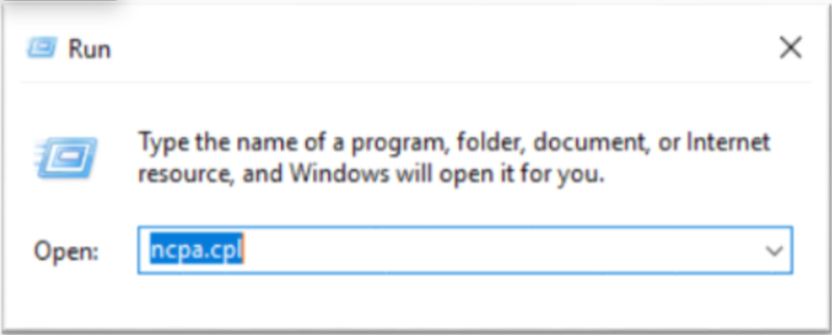
Check whether the interface is enabled, and enable it if necessary.
- Activate the Interface Name identified on the Bare Metal Server Details page.
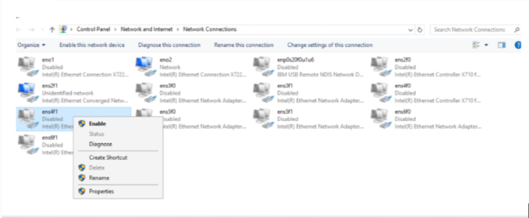
- Activate the Interface Name identified on the Bare Metal Server Details page.
Create a Teaming.
Color modePS C:\> New-NetLbfoTeam –Name “bond-mgt” –TeamMembers ens2f1,ens4f1 PS C:\> Set-NetLbfoTeam –Name “bond-mgt” –LoadBalancingAlgorithm DynamicPS C:\> New-NetLbfoTeam –Name “bond-mgt” –TeamMembers ens2f1,ens4f1 PS C:\> Set-NetLbfoTeam –Name “bond-mgt” –LoadBalancingAlgorithm DynamicCode block. Create Teaming 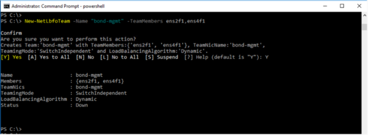
After adding a new VLAN, configure the IP.
- Enter the VLAN ID and local Subnet IP confirmed on the Bare Metal Server Details page.Color mode
PS C:\> Add-NetLbfoTeamNIC -Team bond_bond-mgt -VlanID 20 -Name bond-mgt.20 PS C:\> Get-NetAdapter PS C:\> netsh interface ip set address bond-mgt.20 static “192.168.0.10/24”PS C:\> Add-NetLbfoTeamNIC -Team bond_bond-mgt -VlanID 20 -Name bond-mgt.20 PS C:\> Get-NetAdapter PS C:\> netsh interface ip set address bond-mgt.20 static “192.168.0.10/24”Code block. Windows IP configuration
- Enter the VLAN ID and local Subnet IP confirmed on the Bare Metal Server Details page.
In the Windows Run menu, execute ncpa.cpl to check the interface status.
First connection(kr-south)
If there is no local subnet connected to the Bare Metal Server and you are adding the first connection, follow the guide below.
This guide applies to kr-south(Korea region) when adding the first local Subnet connection to the server.
- For kr-west(Korea West), refer to the First Connection (kr-west) chapter.
Linux - Setting up Subnet on Ubuntu
To add a local Subnet and configure the network on an Ubuntu operating system, follow these steps.
After adding a new VLAN, set the IP.
- Replace the example code’s ID and IP with the assigned ID and IP.Color mode
[root@localhost ~]# vi /etc/netplan/50-cloud-init.yaml network: bonds: bond-mgt: interfaces: - ens2f1 - ens4f1 mtu: 1500 parameters: mii-monitor-interval: 100 mode: active-backup transmit-hash-policy: layer2 ethernets: ens2f1: match: macaddress: 68:05:ca:d4:09:91 mtu: 1500 set-name: ens2f1 ens4f1: match: macaddress: 68:05:ca:d4:09:01 mtu: 1500 set-name: ens4f1 vlans: bond-mgt.20: addresses: - 192.168.0.10/24 id: 20 link: bond-mgt mtu: 1500 vlans: bond-mgt.21: // Enter the VLAN ID you verified on the console instead of 21. addresses: - 192.168.0.20/24 // Set it to the local Subnet IP verified in the console. id: 21 // Set to the VLAN ID verified in the console. link: bond-mgt mtu: 1500[root@localhost ~]# vi /etc/netplan/50-cloud-init.yaml network: bonds: bond-mgt: interfaces: - ens2f1 - ens4f1 mtu: 1500 parameters: mii-monitor-interval: 100 mode: active-backup transmit-hash-policy: layer2 ethernets: ens2f1: match: macaddress: 68:05:ca:d4:09:91 mtu: 1500 set-name: ens2f1 ens4f1: match: macaddress: 68:05:ca:d4:09:01 mtu: 1500 set-name: ens4f1 vlans: bond-mgt.20: addresses: - 192.168.0.10/24 id: 20 link: bond-mgt mtu: 1500 vlans: bond-mgt.21: // Enter the VLAN ID you verified on the console instead of 21. addresses: - 192.168.0.20/24 // Set it to the local Subnet IP verified in the console. id: 21 // Set to the VLAN ID verified in the console. link: bond-mgt mtu: 1500code block. Add Vlan and set IP
- Replace the example code’s ID and IP with the assigned ID and IP.
Apply the changes to the system.
Color mode# netplan apply# netplan applyCode block. Reflect changes Check the interface status.
Color mode# ip a or # bash /usr/local/bin/ip.sh# ip a or # bash /usr/local/bin/ip.shCode block. Interface lookup
Linux – Configuring Subnet on CentOS/Red Hat
CentOS/Red Hat operating system, after adding a local Subnet, follow these steps to configure the network.
- Check the Bond Name for the local Subnet.Color mode
# sh /usr/local/bin/ip.sh# sh /usr/local/bin/ip.shcode block. Verify bonding - Modify the following command and execute it.Color mode
#!/usr/bin/bash IP_ADDR="10.1.1.3/24" // Set the local Subnet IP as observed in the Console. VLAN_ID="7" // Set the Vlan ID as observed in the console. BOND_NAME="bond-mgt" // 1. Set the Bond Name you confirmed. # add vlan nmcli conn add type vlan ifname "${BOND_NAME}.${VLAN_ID}" con-name "${BOND_NAME}.${VLAN_ID}" id ${VLAN_ID} dev ${BOND_NAME} nmcli con mod ${BOND_NAME}.${VLAN_ID} con-name "Vlan ${BOND_NAME}.${VLAN_ID}" nmcli con mod "Vlan ${BOND_NAME}.${VLAN_ID}" ipv4.addresses ${IP_ADDR} nmcli con mod "Vlan ${BOND_NAME}.${VLAN_ID}" ipv4.method manual nmcli con mod "Vlan ${BOND_NAME}.${VLAN_ID}" ipv6.method "ignore" nmcli con mod "Vlan ${BOND_NAME}.${VLAN_ID}" connect.autoconnect yes nmcli con up "Vlan ${BOND_NAME}.${VLAN_ID}" nmcli device reapply ${BOND_NAME}.${VLAN_ID}#!/usr/bin/bash IP_ADDR="10.1.1.3/24" // Set the local Subnet IP as observed in the Console. VLAN_ID="7" // Set the Vlan ID as observed in the console. BOND_NAME="bond-mgt" // 1. Set the Bond Name you confirmed. # add vlan nmcli conn add type vlan ifname "${BOND_NAME}.${VLAN_ID}" con-name "${BOND_NAME}.${VLAN_ID}" id ${VLAN_ID} dev ${BOND_NAME} nmcli con mod ${BOND_NAME}.${VLAN_ID} con-name "Vlan ${BOND_NAME}.${VLAN_ID}" nmcli con mod "Vlan ${BOND_NAME}.${VLAN_ID}" ipv4.addresses ${IP_ADDR} nmcli con mod "Vlan ${BOND_NAME}.${VLAN_ID}" ipv4.method manual nmcli con mod "Vlan ${BOND_NAME}.${VLAN_ID}" ipv6.method "ignore" nmcli con mod "Vlan ${BOND_NAME}.${VLAN_ID}" connect.autoconnect yes nmcli con up "Vlan ${BOND_NAME}.${VLAN_ID}" nmcli device reapply ${BOND_NAME}.${VLAN_ID}Code block. IP configuration script - Check the interface status.Color mode
# ip a
or
# bash /usr/local/bin/ip.sh
# ip a or # bash /usr/local/bin/ip.shCode block. Interface lookup
Configuring Subnet on Windows
After adding a local Subnet on the Windows operating system, follow these steps to configure the network.
Windows Start icon, right-click it, then run the Windows PowerShell(Administrator) program.
Check the Teaming name for the local Subnet.
Color modePS C:\> Get-NetAdapterPS C:\> Get-NetAdaptercode block. Check Windows interface After adding a new VLAN, set the IP.
- Enter the Teaming name confirmed in step 2, and the Vlan ID and local Subnet IP confirmed in the Console.Color mode
PS C:\> Add-NetLbfoTeamNIC -Team bond_bond-mgt -VlanID 20 -Name bond-mgt.20 PS C:\> Get-NetAdapter PS C:\> netsh interface ip set address bond-mgt.20 static “192.168.0.10/24”PS C:\> Add-NetLbfoTeamNIC -Team bond_bond-mgt -VlanID 20 -Name bond-mgt.20 PS C:\> Get-NetAdapter PS C:\> netsh interface ip set address bond-mgt.20 static “192.168.0.10/24”Code block. Create Teaming
- Enter the Teaming name confirmed in step 2, and the Vlan ID and local Subnet IP confirmed in the Console.
In the Windows Run menu, execute ncpa.cpl to check the interface status.
Add second connection (kr-west, kr-south)
If there is a local subnet connected to the Bare Metal Server, the guide for the second additional connection is below.
Because a Bonding was already created when connecting the first local Subnet, there is no procedure to create Bonding when connecting the second local Subnet.
Please refer to the details below.
Linux - Setting up Subnet on Ubuntu
To add a local Subnet and configure the network on an Ubuntu operating system, follow these steps.
After adding a new VLAN, set the IP.
- Replace the example code’s ID and IP with the assigned ID and IP.Color mode
[root@localhost ~]# vi /etc/netplan/50-cloud-init.yaml network: bonds: bond-mgt: interfaces: - ens2f1 - ens4f1 mtu: 1500 parameters: mii-monitor-interval: 100 mode: active-backup transmit-hash-policy: layer2 ethernets: ens2f1: match: macaddress: 68:05:ca:d4:09:91 mtu: 1500 set-name: ens2f1 ens4f1: match: macaddress: 68:05:ca:d4:09:01 mtu: 1500 set-name: ens4f1 vlans: bond-mgt.20: addresses: - 192.168.0.10/24 id: 20 link: bond-mgt mtu: 1500 vlans: bond-mgt.21: // Enter the VLAN ID you verified on the console instead of 21. addresses: - 192.168.0.20/24 // Set it to the local Subnet IP verified in the console. id: 21 // Set to the VLAN ID verified in the console. link: bond-mgt mtu: 1500[root@localhost ~]# vi /etc/netplan/50-cloud-init.yaml network: bonds: bond-mgt: interfaces: - ens2f1 - ens4f1 mtu: 1500 parameters: mii-monitor-interval: 100 mode: active-backup transmit-hash-policy: layer2 ethernets: ens2f1: match: macaddress: 68:05:ca:d4:09:91 mtu: 1500 set-name: ens2f1 ens4f1: match: macaddress: 68:05:ca:d4:09:01 mtu: 1500 set-name: ens4f1 vlans: bond-mgt.20: addresses: - 192.168.0.10/24 id: 20 link: bond-mgt mtu: 1500 vlans: bond-mgt.21: // Enter the VLAN ID you verified on the console instead of 21. addresses: - 192.168.0.20/24 // Set it to the local Subnet IP verified in the console. id: 21 // Set to the VLAN ID verified in the console. link: bond-mgt mtu: 1500code block. Add Vlan and set IP
- Replace the example code’s ID and IP with the assigned ID and IP.
Apply the changes to the system.
Color mode# netplan apply# netplan applyCode block. Reflect changes Check the interface status.
Color mode# ip a or # bash /usr/local/bin/ip.sh# ip a or # bash /usr/local/bin/ip.shCode block. Interface lookup
Linux – Configuring Subnet on CentOS/Red Hat
After adding a local Subnet on CentOS/Red Hat operating systems, follow the steps below to configure the network.
- Check the Bond Name for the local Subnet.Color mode
# sh /usr/local/bin/ip.sh# sh /usr/local/bin/ip.shcode block. Verify bonding - Modify the following command and execute it.Color mode
#!/usr/bin/bash IP_ADDR="10.1.1.3/24" // Set the local Subnet IP as observed in the Console. VLAN_ID="7" // Set the Vlan ID as observed in the console. BOND_NAME="bond-mgt" // 1. Set the Bond Name you confirmed. # add vlan nmcli conn add type vlan ifname "${BOND_NAME}.${VLAN_ID}" con-name "${BOND_NAME}.${VLAN_ID}" id ${VLAN_ID} dev ${BOND_NAME} nmcli con mod ${BOND_NAME}.${VLAN_ID} con-name "Vlan ${BOND_NAME}.${VLAN_ID}" nmcli con mod "Vlan ${BOND_NAME}.${VLAN_ID}" ipv4.addresses ${IP_ADDR} nmcli con mod "Vlan ${BOND_NAME}.${VLAN_ID}" ipv4.method manual nmcli con mod "Vlan ${BOND_NAME}.${VLAN_ID}" ipv6.method "ignore" nmcli con mod "Vlan ${BOND_NAME}.${VLAN_ID}" connect.autoconnect yes nmcli con up "Vlan ${BOND_NAME}.${VLAN_ID}" nmcli device reapply ${BOND_NAME}.${VLAN_ID}#!/usr/bin/bash IP_ADDR="10.1.1.3/24" // Set the local Subnet IP as observed in the Console. VLAN_ID="7" // Set the Vlan ID as observed in the console. BOND_NAME="bond-mgt" // 1. Set the Bond Name you confirmed. # add vlan nmcli conn add type vlan ifname "${BOND_NAME}.${VLAN_ID}" con-name "${BOND_NAME}.${VLAN_ID}" id ${VLAN_ID} dev ${BOND_NAME} nmcli con mod ${BOND_NAME}.${VLAN_ID} con-name "Vlan ${BOND_NAME}.${VLAN_ID}" nmcli con mod "Vlan ${BOND_NAME}.${VLAN_ID}" ipv4.addresses ${IP_ADDR} nmcli con mod "Vlan ${BOND_NAME}.${VLAN_ID}" ipv4.method manual nmcli con mod "Vlan ${BOND_NAME}.${VLAN_ID}" ipv6.method "ignore" nmcli con mod "Vlan ${BOND_NAME}.${VLAN_ID}" connect.autoconnect yes nmcli con up "Vlan ${BOND_NAME}.${VLAN_ID}" nmcli device reapply ${BOND_NAME}.${VLAN_ID}Code block. IP configuration script - Check the interface status.Color mode
# ip a or # bash /usr/local/bin/ip.sh# ip a or # bash /usr/local/bin/ip.shCode block. Interface lookup
Configuring Subnet on Windows
After adding a local Subnet on the Windows operating system, follow these steps to configure the network.
Windows Start icon, right-click it, then run the Windows PowerShell(Administrator) program.
Check the Teaming name for the local Subnet.
Color modePS C:\> Get-NetAdapterPS C:\> Get-NetAdaptercode block. Check Windows interface After adding a new VLAN, configure the IP.
- Enter the Teaming name confirmed in step 2, the Vlan ID confirmed in the Console, and the local Subnet IP.Color mode
PS C:\> Add-NetLbfoTeamNIC -Team bond_bond-mgt -VlanID 20 -Name bond-mgt.20
PS C:\> Get-NetAdapter
PS C:\> netsh interface ip set address bond-mgt.20 static “192.168.0.10/24”
PS C:\> Add-NetLbfoTeamNIC -Team bond_bond-mgt -VlanID 20 -Name bond-mgt.20 PS C:\> Get-NetAdapter PS C:\> netsh interface ip set address bond-mgt.20 static “192.168.0.10/24”Code block. Create Teaming
- Enter the Teaming name confirmed in step 2, the Vlan ID confirmed in the Console, and the local Subnet IP.
In the Windows Run menu, execute ncpa.cpl to check the interface status.
Change IP
The IP can be changed to carry out migration, server replacement, and similar tasks.
- If you proceed with changing the IP, you will no longer be able to communicate using that IP, and you cannot cancel the IP change while it is in progress.
- If the server is running the Load Balancer service, you must delete the old IP from the LB server group and directly add the new IP as a member of the LB server group.
- Servers using Public NAT, Privat NAT must disable and reconfigure Public NAT, Privat NAT after an IP change.
- If you are using Public NAT and Privat NAT, first disable the use of Public NAT and Privat NAT, complete the IP change, and then reconfigure.
- Whether to use Public NAT and Privat NAT can be changed by clicking the Edit button for Public NAT IP and Privat NAT on the Bare Metal Server Details page.
Follow these steps to change the IP.
All Services > Compute > Bare Metal Server Click the menu. 1. Go to the Service Home page of the Bare Metal Server.
On the Service Home page, click the Bare Metal Server menu. 2. Go to the Bare Metal Server List page.
Bare Metal Server List page, click the server whose IP you want to change. Navigate to the Bare Metal Server Detail page.
On the Bare Metal Server Details page, click the Edit button next to the IP field.
When the popup notifying IP modification opens, click the Confirm button. 5. IP Change The popup window opens.
IP Change popup window’s Step 1, Step 2, Step 3 tasks should be performed sequentially.
Notice- When changing the IP, the detailed configuration method for the IP change step varies depending on the subnet of the IP to be changed. * Be sure to refer to the following example and proceed with the tasks step by step.
- When changing to an IP that uses the same subnet: Change to an IP of the same Subnet Reference
- When changing to an IP that uses a different subnet: Change to IP of a different Subnet See
- When each step is completed successfully, the task status in the upper right corner is displayed as Completed, and you can proceed to the next step.
- When performing the final check of Step 3, it is recommended to restart the server before proceeding with the inspection.
- When changing the IP, the detailed configuration method for the IP change step varies depending on the subnet of the IP to be changed. * Be sure to refer to the following example and proceed with the tasks step by step.
After confirming that all tasks have completed successfully, click the Confirm button.
Change to an IP in the same Subnet
This explains how to configure IP settings per operating system when the IP to be changed uses the same subnet.
Linux – centos/redhat operating system
Step 1
Follow the steps below and proceed with Step 1.
- Select the Subnet to modify.
- Enter the IP to change.
- Click the IP Allocation Request button.
- When a pop-up notifying you of an IP change opens, click the Confirm button.
- When the task completes successfully, the task status in the upper right corner will be displayed as Completed.CautionIf you proceed with the IP allocation request of Step 1, you cannot cancel or restore the IP change.
- When the task completes successfully, the task status in the upper right corner will be displayed as Completed.
Step 2
Follow the steps below to perform Step 2.
For the IP change operation, connect to the target server using the NAT IP.
NoticeTo prevent communication failures during operation, it is recommended to connect through another Virtual Server or Bare Metal Server created in the same subnet.Enter the assigned IP from Step 1 and set the new IP on the server.
- In the following example, replace
172.17.34.150with the assigned IP address. - After checking the information of the Interface you want to change on the server, replace it with
bond-srv.9in the following example.Color mode# nmcli con mod "Vlan bond-srv.9" ipv4.addresses 172.17.34.150/24 # nmcli con mod "Vlan bond-srv.9" ipv4.method manual # nmcli device reapply bond-srv.9# nmcli con mod "Vlan bond-srv.9" ipv4.addresses 172.17.34.150/24 # nmcli con mod "Vlan bond-srv.9" ipv4.method manual # nmcli device reapply bond-srv.9Code block. IP settings to modify Notice- Setting the IP disconnects the terminal session.
- Step 2 After completing the task, if the task status changes to Completed, you can reconnect to the terminal.
- In the following example, replace
When all tasks are completed, select the task completion checkbox for Step 2 in the IP 변경 popup window.
- When the task completes successfully, the task status in the upper right corner will be displayed as Completed.Notice
- If the task status of Step 2 has changed to Completed but you still have issues with terminal access, go to the All Services > Management > Support Center Contact Us menu and contact us.
- When the task completes successfully, the task status in the upper right corner will be displayed as Completed.
Step 3
Proceed with Step 3 according to the following procedure.
Connect to the server to be changed using the NAT IP and check its communication status.
- Use the following command to verify whether any pre‑change configuration information remains and whether the change was applied correctly. * If you can successfully connect to the server targeted for IP change, the changed IP is in normal communication state.Color mode
# bash /usr/local/bin/ip.sh# bash /usr/local/bin/ip.shCode block. Communication status check ReferenceThe NAT IP does not change.
- Use the following command to verify whether any pre‑change configuration information remains and whether the change was applied correctly. * If you can successfully connect to the server targeted for IP change, the changed IP is in normal communication state.
After all tasks are completed, restart the server and then perform a final check.
ReferenceIt is recommended to perform the final check after restarting the server.If the final inspection shows no issues, select the work‑completion checkbox for Step 3 in the IP change popup.
Linux – Ubuntu operating system
Step 1
Follow the steps below and proceed with Step 1.
- Select the Subnet to modify.
- Enter the IP to change.
- Click the IP Allocation Request button.
- When a pop-up notifying you of an IP change opens, click the Confirm button.
- When the task completes successfully, the task status in the upper right corner will be displayed as Completed.CautionIf you proceed with the IP allocation request of Step 1, you cannot cancel or restore the IP change.
- When the task completes successfully, the task status in the upper right corner will be displayed as Completed.
Step 2
Follow the steps below to perform Step 2.
For the IP change operation, connect to the target server using the NAT IP.
NoticeTo prevent communication failures during operation, it is recommended to connect through another Virtual Server or Bare Metal Server created in the same subnet.Enter the assigned IP from Step 1 and set the new IP on the server.
- In the following example, replace
172.17.34.150/24with the assigned IP address. - After checking the information of the Interface you want to change on the server, replace it with
bond-srv.9in the following example.Color mode[root@localhost ~]# vi /etc/netplan/50-cloud-init.yaml network: bonds: ...................... Omitted ethernets: ...................... Omitted vlans: bond-srv.9: addresses: - 172.17.34.150/24 # Enter the IP assigned in Step1. gateway4: 172.17.34.2 id: 9 link: bond-srv mtu: 1500 bond-srv.350: addresses: - 172.16.87.150/24 routes: - to: 172.17.87.0/24 via: 172.16.87.1 - to: 172.17.87.0/24 via: 172.16.87.1 id: 350 link: bond-srv[root@localhost ~]# vi /etc/netplan/50-cloud-init.yaml network: bonds: ...................... Omitted ethernets: ...................... Omitted vlans: bond-srv.9: addresses: - 172.17.34.150/24 # Enter the IP assigned in Step1. gateway4: 172.17.34.2 id: 9 link: bond-srv mtu: 1500 bond-srv.350: addresses: - 172.16.87.150/24 routes: - to: 172.17.87.0/24 via: 172.16.87.1 - to: 172.17.87.0/24 via: 172.16.87.1 id: 350 link: bond-srvCode block. IP settings to modify
- In the following example, replace
Use the Netplan apply command to apply the changes to the system.
Color mode[root@localhost ~]# netplan apply[root@localhost ~]# netplan applyCode block. Run Netplan apply Notice- Setting the IP disconnects the terminal session.
- Step 2 After completing the task, if the task status changes to Completed, you can reconnect to the terminal.
When all tasks are completed, select the task completion checkbox for Step 2 in the IP Change popup.
- When the task completes successfully, the task status in the upper right corner will be displayed as Completed.Notice
- If the task status of Step 2 has changed to Completed but you still have issues with terminal access, go to the All Services > Management > Support Center Contact Us menu and submit an inquiry.
- When the task completes successfully, the task status in the upper right corner will be displayed as Completed.
Step 3
Proceed with Step 3 according to the following procedure.
Connect to the server to be changed using the NAT IP and check its communication status.
- Use the following command to verify whether any pre‑change configuration information remains and whether the change was applied correctly. * If you can successfully connect to the server targeted for IP change, the new IP is operating normally.Color mode
# bash /usr/local/bin/ip.sh# bash /usr/local/bin/ip.shCode block. Communication status check ReferenceThe NAT IP does not change.
- Use the following command to verify whether any pre‑change configuration information remains and whether the change was applied correctly. * If you can successfully connect to the server targeted for IP change, the new IP is operating normally.
After all tasks are completed, restart the server and then perform a final check.
ReferenceIt is recommended to perform the final check after restarting the server.If there are no issues in the final inspection results, select the work completion checkbox for Step 3 in the IP Change popup window.
Windows operating system
Step 1
Follow the steps below and proceed with Step 1.
- Select the Subnet to modify.
- Enter the IP to change.
- Click the IP Allocation Request button.
- When the popup notifying IP change verification opens, click the Confirm button.
- When the task completes successfully, the task status in the upper right corner will be displayed as Completed.CautionIf you proceed with the IP allocation request of Step 1, you cannot cancel or restore the IP change.
- When the task completes successfully, the task status in the upper right corner will be displayed as Completed.
Step 2
Follow the steps below to perform Step 2.
For the IP change operation, connect to the target server using the NAT IP.
NoticeTo prevent communication failures during operation, it is recommended to connect through another Virtual Server or Bare Metal Server created in the same subnet.Windows Start icon, right‑click it, then run Windows PowerShell(Administrator).
Enter the assigned IP from Step 1 and set the new IP on the server.
- In the following example, replace
172.17.34.150with the assigned IP address.Color modePS C:\> netsh interface ip set address "bond-srv.20" static 172.17.34.150 255.255.255.0PS C:\> netsh interface ip set address "bond-srv.20" static 172.17.34.150 255.255.255.0Code block. IP settings to modify Notice- Setting the IP disconnects the terminal session.
- Step 2 After completing the task, if the task status changes to Completed, you can reconnect to the terminal.
- In the following example, replace
When all tasks are completed, select the task completion checkbox for Step 2 in the IP 변경 popup window.
- When the task completes successfully, the task status in the upper right corner will be displayed as Completed.Notice
- If the task status of Step 2 has changed to Completed but you still have issues with terminal access, go to the All Services > Management > Support Center Contact Us menu and contact us.
- When the task completes successfully, the task status in the upper right corner will be displayed as Completed.
Step 3
Proceed with Step 3 according to the following procedure.
Connect to the server to be changed using the NAT IP and check its communication status.
- Use the following command to verify whether any pre‑change configuration information remains and whether the change was applied correctly. * If you can successfully connect to the server targeted for IP change, the changed IP is in normal communication state.Color mode
PS C:\> Get-NetIPAddress | Format-TablePS C:\> Get-NetIPAddress | Format-TableCode block. Communication status check ReferenceThe NAT IP does not change.
- Use the following command to verify whether any pre‑change configuration information remains and whether the change was applied correctly. * If you can successfully connect to the server targeted for IP change, the changed IP is in normal communication state.
After all tasks are completed, restart the server and then perform a final check.
ReferenceIt is recommended to perform the final check after restarting the server.If there are no issues in the final inspection results, select the work completion checkbox for Step 3 in the IP Change popup window.
Change to IP of another Subnet
This explains how to configure IP settings for each operating system when the IP to be changed uses a different subnet.
Linux – centos/redhat operating system
Step 1
Follow the steps below and proceed with Step 1.
- Select the Subnet to modify.
- Enter the IP to change.
- Click the IP Allocation Request button.
- When the popup notifying IP change verification opens, click the Confirm button.
- When the operation completes successfully, Vlan ID check, Default Gateway check information is displayed, and the operation status in the upper right corner shows Completed.CautionIf you proceed with the IP allocation request of Step 1, you cannot cancel or restore the IP change.
- When the operation completes successfully, Vlan ID check, Default Gateway check information is displayed, and the operation status in the upper right corner shows Completed.
Step 2
Follow the steps below to perform Step 2.
For the IP change operation, connect to the target server using the NAT IP.
NoticeTo prevent communication failures during operation, it is recommended to connect through another Virtual Server or Bare Metal Server created in the same subnet.Add a new VLAN and configure the IP to add the IP to the server.
- Add VLAN: Create the interface of the Vlan ID identified in Step 1. * In the following example, enter the assigned ID instead of
20. - IP configuration: Enter the IP assigned in Step 1. * In the following example, replace
192.168.0.10/24with the assigned IP address.Color mode# nmcli conn add type vlan ifname "bond-srv.20" con-name "bond-srv.20" id 20 dev bond-srv # nmcli con mod bond-srv.20 con-name "Vlan bond-srv.20" # nmcli con mod "Vlan bond-srv.20" ipv4.addresses 192.168.0.10/24 # nmcli con mod "Vlan bond-srv.20" ipv4.method manual # nmcli con mod "Vlan bond-srv.20" ipv6.method "ignore" # nmcli con up "Vlan bond-srv.20"# nmcli conn add type vlan ifname "bond-srv.20" con-name "bond-srv.20" id 20 dev bond-srv # nmcli con mod bond-srv.20 con-name "Vlan bond-srv.20" # nmcli con mod "Vlan bond-srv.20" ipv4.addresses 192.168.0.10/24 # nmcli con mod "Vlan bond-srv.20" ipv4.method manual # nmcli con mod "Vlan bond-srv.20" ipv6.method "ignore" # nmcli con up "Vlan bond-srv.20"Code block. IP settings to modify
- Add VLAN: Create the interface of the Vlan ID identified in Step 1. * In the following example, enter the assigned ID instead of
Set the default gateway for the new VLAN.
- Default gateway configuration: Enter the Default gateway IP assigned in Step 1. * In the following example, replace
192.168.0.1with the assigned Default gateway IP.Color mode# nmcli con mod "Vlan bond-srv.20" ipv4.gateway 192.168.0.1 # nmcli device reapply bond-srv.20# nmcli con mod "Vlan bond-srv.20" ipv4.gateway 192.168.0.1 # nmcli device reapply bond-srv.20Code block. IP settings to modify Notice- If you set a Default Gateway on a new VLAN, the terminal session gets disconnected.
- Step 2 After completing the task, if the task status changes to Completed, you can reconnect to the terminal.
- Default gateway configuration: Enter the Default gateway IP assigned in Step 1. * In the following example, replace
When all tasks are completed, select the task completion checkbox for Step 2 in the IP 변경 popup window.
- When the task completes successfully, the task status in the upper right corner will be displayed as Completed.Notice
- If the task status of Step 2 has changed to Completed but you still experience problems with terminal access, navigate to the All Services > Management > Support Center Contact Us menu and submit an inquiry.
- When the task completes successfully, the task status in the upper right corner will be displayed as Completed.
Step 3
Proceed with Step 3 according to the following procedure.
Connect to the server subject to IP change using a NAT IP.
Verify the Default Gateway IP of the existing (pre-change) interface, then delete it.
- In the following example, replace
192.168.10.1with the IP you verified.Color mode# ip route del default via 192.168.10.1# ip route del default via 192.168.10.1Code block. Delete the Default Gateway IP of the existing interface
- In the following example, replace
Connect to the server to be changed using the NAT IP and check its communication status.
- Use the following command to verify whether any pre‑change configuration information remains and whether the changes were applied correctly. * If you can successfully connect to the server targeted for IP change, the changed IP is in normal communication state.Color mode
# netstat –nr
# bash /usr/local/bin/ip.sh
# netstat –nr # bash /usr/local/bin/ip.shCode block. Communication status check ReferenceThe NAT IP does not change.
- Use the following command to verify whether any pre‑change configuration information remains and whether the changes were applied correctly. * If you can successfully connect to the server targeted for IP change, the changed IP is in normal communication state.
Check the VLAN information of the existing IP and then delete it from the server.
- Enter the verified ID in place of
30in the following example.Color mode# nmcli con delete "Vlan bond-srv.30"# nmcli con delete "Vlan bond-srv.30"Code block. Delete the VLAN information of the existing IP.
- Enter the verified ID in place of
After all tasks are completed, restart the server and then perform a final check.
ReferenceIt is recommended to perform the final check after restarting the server.If the final inspection results show no issues, select the work‑completion checkbox for Step 3 in the IP Change popup window.
Linux – Ubuntu operating system
Step 1
Follow the steps below and proceed with Step 1.
- Select the Subnet to modify.
- Enter the IP to change.
- Click the IP Allocation Request button.
- When a popup that notifies IP change verification opens, click the Confirm button.
- When the operation completes successfully, Vlan ID check, Default Gateway check information is displayed, and the operation status in the upper right corner shows Completed.CautionIf you proceed with the IP allocation request of Step 1, you cannot cancel or restore the IP change.
- When the operation completes successfully, Vlan ID check, Default Gateway check information is displayed, and the operation status in the upper right corner shows Completed.
Step 2
Follow the steps below to perform Step 2.
For the IP change operation, connect to the target server using the NAT IP.
NoticeTo prevent communication failures during operation, it is recommended to connect through another Virtual Server or Bare Metal Server created in the same subnet.Add a new VLAN and set the IP and Default Gateway to add the IP to the server.
- In the following example, this is the part where content is added at the bottom of the Step 1 task description.
- In the following example, enter the assigned ID and IP instead of ID and IP.Color mode
[root@localhost ~]# vi /etc/netplan/50-cloud-init.yaml network: bonds: ...................... Omitted ethernets: ...................... Omitted vlans: bond-srv.9: addresses: - 172.17.34.150/24 gateway4: 172.17.34.2 id: 9 link: bond-srv mtu: 1500 bond-srv.350: addresses: - 172.16.87.150/24 routes: - to: 172.17.87.0/24 via: 172.16.87.1 - to: 172.17.87.0/24 via: 172.16.87.1 id: 350 link: bond-srv # Create the interface for the Vlan ID identified in Step1. # Enter the IP assigned in Step1. # Enter the Default gateway IP assigned in Step1. bond-srv.20: addresses: - 192.168.0.10/24 gateway4: 192.168.0.1 id: 20 link: bond-srv mtu: 1500[root@localhost ~]# vi /etc/netplan/50-cloud-init.yaml network: bonds: ...................... Omitted ethernets: ...................... Omitted vlans: bond-srv.9: addresses: - 172.17.34.150/24 gateway4: 172.17.34.2 id: 9 link: bond-srv mtu: 1500 bond-srv.350: addresses: - 172.16.87.150/24 routes: - to: 172.17.87.0/24 via: 172.16.87.1 - to: 172.17.87.0/24 via: 172.16.87.1 id: 350 link: bond-srv # Create the interface for the Vlan ID identified in Step1. # Enter the IP assigned in Step1. # Enter the Default gateway IP assigned in Step1. bond-srv.20: addresses: - 192.168.0.10/24 gateway4: 192.168.0.1 id: 20 link: bond-srv mtu: 1500Code block. IP settings to modify
Use the Netplan apply command to apply the changes to the system.
Color mode[root@localhost ~]# netplan apply[root@localhost ~]# netplan applyCode block. Run Netplan apply Notice- If you set a new Default Gateway, the terminal session will be disconnected.
- Step 2 After completing the task, if the task status changes to Completed, you can reconnect to the terminal.
When all tasks are completed, select the task completion checkbox for Step 2 in the IP 변경 popup window.
- When the task completes successfully, the task status in the upper right corner will be displayed as Completed.Notice
- If the task status of Step 2 has changed to Completed but you still experience problems with terminal access, navigate to the All Services > Management > Support Center Contact Us menu and submit an inquiry.
- When the task completes successfully, the task status in the upper right corner will be displayed as Completed.
Step 3
Proceed with Step 3 according to the following procedure.
Connect to the server subject to IP change using a NAT IP.
Verify the Default Gateway IP of the existing (pre-change) interface, then delete it.
- In the following example, the Delete this line row is the part that gets deleted.Color mode
[root@localhost ~]# vi /etc/netplan/50-cloud-init.yaml network: bonds: ...................... Omitted ethernets: ...................... Omitted vlans: bond-srv.9: addresses: - 172.17.34.150/24 gateway4: 172.17.34.2 #Delete this line id: 9 link: bond-srv mtu: 1500 bond-srv.350: addresses: - 172.16.87.150/24 routes: - to: 172.17.87.0/24 via: 172.16.87.1 - to: 172.17.87.0/24 via: 172.16.87.1 id: 350 link: bond-srv bond-srv.20: addresses: - 192.168.0.10/24 gateway4: 192.168.0.1 id: 20 link: bond-srv mtu: 1500[root@localhost ~]# vi /etc/netplan/50-cloud-init.yaml network: bonds: ...................... Omitted ethernets: ...................... Omitted vlans: bond-srv.9: addresses: - 172.17.34.150/24 gateway4: 172.17.34.2 #Delete this line id: 9 link: bond-srv mtu: 1500 bond-srv.350: addresses: - 172.16.87.150/24 routes: - to: 172.17.87.0/24 via: 172.16.87.1 - to: 172.17.87.0/24 via: 172.16.87.1 id: 350 link: bond-srv bond-srv.20: addresses: - 192.168.0.10/24 gateway4: 192.168.0.1 id: 20 link: bond-srv mtu: 1500Code block. Delete the Default Gateway IP of the existing interface
- In the following example, the Delete this line row is the part that gets deleted.
Connect to the server to be changed using the NAT IP and check its communication status.
- Use the following command to verify whether any pre‑change configuration information remains and whether the change was applied correctly. * If you can successfully connect to the server targeted for IP change, the changed IP is in normal communication state.Color mode
# netstat –nr # bash /usr/local/bin/ip.sh# netstat –nr # bash /usr/local/bin/ip.shCode block. Communication status check ReferenceThe NAT IP does not change.
- Use the following command to verify whether any pre‑change configuration information remains and whether the change was applied correctly. * If you can successfully connect to the server targeted for IP change, the changed IP is in normal communication state.
Delete the existing IP.
- In the following example, the Delete this line row is the part that gets deleted.Color mode
[root@localhost ~]# vi /etc/netplan/50-cloud-init.yaml network: bonds: ...................... Omitted ethernets: ...................... Omitted vlans: bond-srv.9: #Delete this line addresses: #Delete this line - 172.17.34.150/24 # Delete this line gateway4: 172.17.34.2 #Delete this line id: 9 # Delete this line link: bond-srv #Delete this line mtu: 1500 #Delete this line bond-srv.350: addresses: - 172.16.87.150/24 routes: - to: 172.17.87.0/24 via: 172.16.87.1 - to: 172.17.87.0/24 via: 172.16.87.1 id: 350 link: bond-srv bond-srv.20: addresses: - 192.168.0.10/24 gateway4: 192.168.0.1 id: 20 link: bond-srv mtu: 1[root@localhost ~]# vi /etc/netplan/50-cloud-init.yaml network: bonds: ...................... Omitted ethernets: ...................... Omitted vlans: bond-srv.9: #Delete this line addresses: #Delete this line - 172.17.34.150/24 # Delete this line gateway4: 172.17.34.2 #Delete this line id: 9 # Delete this line link: bond-srv #Delete this line mtu: 1500 #Delete this line bond-srv.350: addresses: - 172.16.87.150/24 routes: - to: 172.17.87.0/24 via: 172.16.87.1 - to: 172.17.87.0/24 via: 172.16.87.1 id: 350 link: bond-srv bond-srv.20: addresses: - 192.168.0.10/24 gateway4: 192.168.0.1 id: 20 link: bond-srv mtu: 1Code block. Delete existing IP
- In the following example, the Delete this line row is the part that gets deleted.
Apply the changes to the system.
Color mode[root@localhost ~]# netplan apply [root@localhost ~]# ip link delete bond-srv.9 # Additional steps when deleting VLAN[root@localhost ~]# netplan apply [root@localhost ~]# ip link delete bond-srv.9 # Additional steps when deleting VLANCode block. Apply changes After all tasks are completed, restart the server and then perform a final check.
- If the final inspection results show no issues, select the work‑completion checkbox for Step 3 in the IP Change popup window.
Windows operating system
Step 1
Follow the steps below and proceed with Step 1.
- Select the Subnet to modify.
- Enter the IP to change.
- Click the IP Allocation Request button.
- When the popup indicating IP change verification opens, click the Confirm button.
- When the operation completes successfully, Vlan ID check, Default Gateway check information is displayed, and the operation status in the upper right corner shows Completed.CautionIf you proceed with the IP allocation request of Step 1, you cannot cancel or restore the IP change.
- When the operation completes successfully, Vlan ID check, Default Gateway check information is displayed, and the operation status in the upper right corner shows Completed.
Step 2
Follow the steps below to perform Step 2.
For the IP change operation, connect to the target server using the NAT IP.
NoticeTo prevent communication failures during operation, it is recommended to connect through another Virtual Server or Bare Metal Server created in the same subnet.Windows Start icon, right-click, then run Windows PowerShell(Administrator).
Add a VLAN and configure the IP and default gateway.
- Add VLAN: Create the interface of the Vlan ID identified in Step 1. * In the following example, enter the assigned ID instead of
20. - IP configuration: Enter the IP assigned in Step 1. * In the following example, replace
46with the ifindex obtained using Get‑NetAdapter, and replace 192.168.0.10 with the assigned IP address. - Default gateway configuration: Enter the Default gateway IP assigned in Step 1. * In the following example, replace
192.168.0.1with the assigned Default gateway IP.Color modePS C:\> Add-NetLbfoTeamNIC -Team bond_bond-srv -VlanID 20 -Name bond-srv.20 -Confirm:$false PS C:\> Get-NetAdapter PS C:\> New-NetIPAddress -InterfaceIndex 46 -IPAddress 192.168.0.10 -PrefixLength 24 –defaultgateway 192.168.0.1PS C:\> Add-NetLbfoTeamNIC -Team bond_bond-srv -VlanID 20 -Name bond-srv.20 -Confirm:$false PS C:\> Get-NetAdapter PS C:\> New-NetIPAddress -InterfaceIndex 46 -IPAddress 192.168.0.10 -PrefixLength 24 –defaultgateway 192.168.0.1Code block. IP settings to modify Notice- If you set a new Default Gateway, the terminal session will be disconnected.
- Step 2 After completing the task, if the task status changes to Completed, you can reconnect to the terminal.
- Add VLAN: Create the interface of the Vlan ID identified in Step 1. * In the following example, enter the assigned ID instead of
When all tasks are completed, select the task completion checkbox for Step 2 in the IP 변경 popup window.
- When the task completes successfully, the task status in the upper right corner will be displayed as Completed.Notice
- If the task status of Step 2 has changed to Completed but you still experience problems with terminal access, navigate to the All Services > Management > Support Center Contact Us menu and submit an inquiry.
- When the task completes successfully, the task status in the upper right corner will be displayed as Completed.
Step 3
Proceed with Step 3 according to the following procedure.
Connect to the server subject to IP change using a NAT IP.
Run the interface index (ifindex) to check the existing Default Gateway IP.
Color modePS C:\> Get-NetAdapter Name InterfaceDescription ifIndex Status MacAddress LinkSpeed ---- -------------------- ------- ------ ---------- --------- bond-srv.9 Microsoft Network Adapter Multiple...#4 30 Up 40-A6-B7-27-96-D5 50 Gbps bond-srv Microsoft Network Adapter Multiple...#3 19 Up 40-A6-B7-27-96-D5 50 Gbps bond-iscsi Microsoft Network Adapter Multiple...#2 18 Up 40-A6-B7-27-96-D4 50 Gbps bond-backup Microsoft Network Adapter Multiplexo... 22 Up 68-05-CA-C9-EB-88 20 Gbps eno2 Intel(R) Ethernet Connection X722 fo... 12 Disabled 38-68-DD-36-A0-59 1 Gbps ens3f0 Intel(R) Ethernet Network Adapter XX... 11 Up 40-A6-B7-27-96-D4 25 Gbps ………………………………………….. OmittedPS C:\> Get-NetAdapter Name InterfaceDescription ifIndex Status MacAddress LinkSpeed ---- -------------------- ------- ------ ---------- --------- bond-srv.9 Microsoft Network Adapter Multiple...#4 30 Up 40-A6-B7-27-96-D5 50 Gbps bond-srv Microsoft Network Adapter Multiple...#3 19 Up 40-A6-B7-27-96-D5 50 Gbps bond-iscsi Microsoft Network Adapter Multiple...#2 18 Up 40-A6-B7-27-96-D4 50 Gbps bond-backup Microsoft Network Adapter Multiplexo... 22 Up 68-05-CA-C9-EB-88 20 Gbps eno2 Intel(R) Ethernet Connection X722 fo... 12 Disabled 38-68-DD-36-A0-59 1 Gbps ens3f0 Intel(R) Ethernet Network Adapter XX... 11 Up 40-A6-B7-27-96-D4 25 Gbps ………………………………………….. Omittedcode block. Run Get-NetAdapter Color modePS C:\> get-netroute -ifindex 30 ifIndex DestinationPrefix NextHop RouteMetric PolicyStore ------- ----------------- ------- ----------- ----------- 30 255.255.255.255/32 0.0.0.0 256 ActiveStore 30 224.0.0.0/4 0.0.0.0 256 ActiveStore 30 172.17.35.0/24 172.17.35.1 256 ActiveStore 30 172.17.34.255/32 0.0.0.0 256 ActiveStore 30 172.17.34.14/32 0.0.0.0 256 ActiveStore 30 172.17.34.0/24 0.0.0.0 256 ActiveStore 30 0.0.0.0/0 172.17.34.1 1 ActiveStorePS C:\> get-netroute -ifindex 30 ifIndex DestinationPrefix NextHop RouteMetric PolicyStore ------- ----------------- ------- ----------- ----------- 30 255.255.255.255/32 0.0.0.0 256 ActiveStore 30 224.0.0.0/4 0.0.0.0 256 ActiveStore 30 172.17.35.0/24 172.17.35.1 256 ActiveStore 30 172.17.34.255/32 0.0.0.0 256 ActiveStore 30 172.17.34.14/32 0.0.0.0 256 ActiveStore 30 172.17.34.0/24 0.0.0.0 256 ActiveStore 30 0.0.0.0/0 172.17.34.1 1 ActiveStoreCode block. Execute -ifindex Delete the existing Default Gateway IP.
- In the following example, replace
30with the ifindex obtained via Get-NetAdapter, and replace172.17.34.1with the IP you obtained.Color modePS C:\> Remove-NetRoute -ifIndex 30 -DestinationPrefix 0.0.0.0/0 -NextHop 172.17.34.1 -Confirm:$falsePS C:\> Remove-NetRoute -ifIndex 30 -DestinationPrefix 0.0.0.0/0 -NextHop 172.17.34.1 -Confirm:$falseCode block. Delete Default Gateway IP Color modePS C:\> get-netroute -ifindex 30 ifIndex DestinationPrefix NextHop RouteMetric PolicyStore ------- ----------------- ------- ----------- ----------- 30 255.255.255.255/32 0.0.0.0 256 ActiveStore 30 224.0.0.0/4 0.0.0.0 256 ActiveStore 30 172.17.34.255/32 0.0.0.0 256 ActiveStore 30 172.17.34.14/32 0.0.0.0 256 ActiveStore 30 172.17.34.0/24 0.0.0.0 256 ActiveStorePS C:\> get-netroute -ifindex 30 ifIndex DestinationPrefix NextHop RouteMetric PolicyStore ------- ----------------- ------- ----------- ----------- 30 255.255.255.255/32 0.0.0.0 256 ActiveStore 30 224.0.0.0/4 0.0.0.0 256 ActiveStore 30 172.17.34.255/32 0.0.0.0 256 ActiveStore 30 172.17.34.14/32 0.0.0.0 256 ActiveStore 30 172.17.34.0/24 0.0.0.0 256 ActiveStoreCode block. Execute -ifindex Notice- If you delete the existing Default Gateway, the terminal session will be disconnected.
- Step 2 After completing the task, if the task status changes to Completed, you can reconnect to the terminal.
- In the following example, replace
Connect to the server to be changed using the NAT IP and check its communication status.
- Use the following command to verify whether any pre‑change configuration information remains and whether the change was applied correctly. * If you can successfully connect to the server targeted for IP change, the changed IP is in normal communication state.Color mode
PS C:\> netstat –nr | findstr Default
PS C:\> Get-NetIPAddress | Format-Table
PS C:\> netstat –nr | findstr Default PS C:\> Get-NetIPAddress | Format-TableCode block. Communication status check ReferenceThe NAT IP does not change.
- Use the following command to verify whether any pre‑change configuration information remains and whether the change was applied correctly. * If you can successfully connect to the server targeted for IP change, the changed IP is in normal communication state.
Check the VLAN information of the existing IP in the Team information.
Color modePS C:\> Get-NetLbfoTeam Name : bond_bond-srv Members : {ens6f1, ens3f1} TeamNics : {bond-srv, bond-srv.9} Team ingMode : SwitchIndependent LoadBalancingAlgorithm : Dynamic Status : Up Name : bond_bond-iscsi Members : {ens6f0, ens3f0} TeamNics : bond-iscsi Team ingMode : SwitchIndependent LoadBalancingAlgorithm : Dynamic Status : Up Name : bond_bond-backup Members : {ens2f0, ens4f1} TeamNics : bond-backup Team ingMode : SwitchIndependent LoadBalancingAlgorithm : Dynamic Status : Up PS C:\> Get-NetAdapter Name InterfaceDescription ifIndex Status MacAddress LinkSpeed ---- -------------------- ------- ------ ---------- --------- bond-srv.9 Microsoft Network Adapter Multiple...#4 30 Up 40-A6-B7-27-96-D5 50 Gbps bond-srv Microsoft Network Adapter Multiple...#3 19 Up 40-A6-B7-27-96-D5 50 Gbps bond-iscsi Microsoft Network Adapter Multiple...#2 18 Up 40-A6-B7-27-96-D4 50 Gbps bond-backup Microsoft Network Adapter Multiplexo... 22 Up 68-05-CA-C9-EB-88 20 Gbps eno2 Intel(R) Ethernet Connection X722 fo... 12 Disabled 38-68-DD-36-A0-59 1 Gbps ens3f0 Intel(R) Ethernet Network Adapter XX... 11 Up 40-A6-B7-27-96-D4 25 Gbps ………………………………………….. OmittedPS C:\> Get-NetLbfoTeam Name : bond_bond-srv Members : {ens6f1, ens3f1} TeamNics : {bond-srv, bond-srv.9} Team ingMode : SwitchIndependent LoadBalancingAlgorithm : Dynamic Status : Up Name : bond_bond-iscsi Members : {ens6f0, ens3f0} TeamNics : bond-iscsi Team ingMode : SwitchIndependent LoadBalancingAlgorithm : Dynamic Status : Up Name : bond_bond-backup Members : {ens2f0, ens4f1} TeamNics : bond-backup Team ingMode : SwitchIndependent LoadBalancingAlgorithm : Dynamic Status : Up PS C:\> Get-NetAdapter Name InterfaceDescription ifIndex Status MacAddress LinkSpeed ---- -------------------- ------- ------ ---------- --------- bond-srv.9 Microsoft Network Adapter Multiple...#4 30 Up 40-A6-B7-27-96-D5 50 Gbps bond-srv Microsoft Network Adapter Multiple...#3 19 Up 40-A6-B7-27-96-D5 50 Gbps bond-iscsi Microsoft Network Adapter Multiple...#2 18 Up 40-A6-B7-27-96-D4 50 Gbps bond-backup Microsoft Network Adapter Multiplexo... 22 Up 68-05-CA-C9-EB-88 20 Gbps eno2 Intel(R) Ethernet Connection X722 fo... 12 Disabled 38-68-DD-36-A0-59 1 Gbps ens3f0 Intel(R) Ethernet Network Adapter XX... 11 Up 40-A6-B7-27-96-D4 25 Gbps ………………………………………….. Omittedcode block. Run Get-NetLbfoTeam Delete the Vlan information of the existing IP from the server.
- Enter the verified ID in place of
30in the following example.Color modePS C:\> Remove-NetLbfoTeamNic -Team bond_bond-srv -VlanID 30 -Confirm:$false PS C:\> Get-NetAdapter Name InterfaceDescription ifIndex Status MacAddress LinkSpeed ---- -------------------- ------- ------ ---------- --------- bond-srv Microsoft Network Adapter Multiple...#3 19 Up 40-A6-B7-27-96-D5 50 Gbps bond-iscsi Microsoft Network Adapter Multiple...#2 18 Up 40-A6-B7-27-96-D4 50 Gbps bond-backup Microsoft Network Adapter Multiplexo... 22 Up 68-05-CA-C9-EB-88 20 Gbps eno2 Intel(R) Ethernet Connection X722 fo... 12 Disabled 38-68-DD-36-A0-59 1 Gbps ens3f0 Intel(R) Ethernet Network Adapter XX... 11 Up 40-A6-B7-27-96-D4 25 Gbps ………………………………………….. OmittedPS C:\> Remove-NetLbfoTeamNic -Team bond_bond-srv -VlanID 30 -Confirm:$false PS C:\> Get-NetAdapter Name InterfaceDescription ifIndex Status MacAddress LinkSpeed ---- -------------------- ------- ------ ---------- --------- bond-srv Microsoft Network Adapter Multiple...#3 19 Up 40-A6-B7-27-96-D5 50 Gbps bond-iscsi Microsoft Network Adapter Multiple...#2 18 Up 40-A6-B7-27-96-D4 50 Gbps bond-backup Microsoft Network Adapter Multiplexo... 22 Up 68-05-CA-C9-EB-88 20 Gbps eno2 Intel(R) Ethernet Connection X722 fo... 12 Disabled 38-68-DD-36-A0-59 1 Gbps ens3f0 Intel(R) Ethernet Network Adapter XX... 11 Up 40-A6-B7-27-96-D4 25 Gbps ………………………………………….. Omittedcode block. Run Get-NetLbfoTeam
- Enter the verified ID in place of
After all tasks are completed, restart the server and then perform a final check.
ReferenceIt is recommended to perform the final check after restarting the server.If the final inspection results show no issues, select the work‑completion checkbox for Step 3 in the IP Change popup window.
Setting up RHEL Repository
The Samsung Cloud Platform Console provides the SCP RHEL Repository to support user environments where external access is restricted, such as VPC Private Subnet.
You can use the RHEL Repository to install and download the same packages as the official RHEL Repository.
To configure the RHEL Repository, refer to the RHEL Repository 설정 가이드.
- If a user created RHEL before August 2025 through the Samsung Cloud Platform Console, they must modify the RHEL Repository settings.
- Since the SCP RHEL Repository synchronizes with each region’s local repository according to an internal schedule, it is recommended to switch to an external public mirror site to apply the latest patches quickly.
- Samsung Cloud Platform provides the latest version repository for the given major version.