Explore the new features of the Samsung Cloud Platform Console~
Resource Management Using Copilot
Information about resources/services
Easy and fast integrated search
Improving accessibility of Account and Favorites
Providing services for large-scale organizations and systematic user management
LLM service that can be used without a separate application
1.2 - Overview
Samsung Cloud Platform
Samsung Cloud Platform is a cloud environment that virtualizes and provides various resource pools such as computing, storage, networking, and databases needed by enterprises.
Through the Samsung Cloud Platform, you can use the required resources in a cloud environment without needing to provide hardware or physical space. Since charges are billed based on actual usage, efficient budget management is possible, and companies can reduce costs associated with building and managing their own server environments.
The main terms used in Samsung Cloud Platform are as follows.
term
Detailed description
Region
Consists of one or more data centers to ensure availability as geographically separated cloud service delivery units.
Account
The basic unit and billing unit required to use the Samsung Cloud Platform service
Root user
User who created the Account and holds top-level privileges
IAM user
A user with restricted permissions created by the root user within the account
Service
Various types of IT services and infrastructure (Compute, Storage, Network, etc.) provided by Samsung Cloud Platform
Resource (resource)
An individual unit entity (Entity) that is created and managed as the user uses the service.
Table. Samsung Cloud Platform key terms
Component
Samsung Cloud Platform provides a Service Portal, Console, and Documentation.
Category
Detailed description
Service Portal
Service and pricing overview for Samsung Cloud Platform, as well as information such as customer support
Console
Self-service interface that provides functions such as creating accounts and resources, and checking costs on the Samsung Cloud Platform.
Documetation
As a documentation service for Samsung Cloud Platform, it provides user guides, API/CLI references, and more.
Table. Samsung Cloud Platform components
region
Regions are geographically distinct units of cloud service provision, composed of one or more data centers to ensure availability. Services offered on the Samsung Cloud Platform are managed by region, so the services provided may vary slightly. Refer to the user guide for each service.
Region name
Region
Western Korea
Korea West (kr-west1)
Eastern Korea
Korea East (kr-east1)
South Korea (administrative)
South Korea South 1 (kr-south1)
South Korea (public)
South Korea 2 (kr-south2)
South Korea (Internet)
South Korea South 3(kr-south3)
Table. Samsung Cloud Platform provided region items
Account
To use the Samsung Cloud Platform, you need to create an Account, which can be done through sign‑up. A user who signs up and creates an Account becomes the Account’s root user and is responsible for payment. Once you sign up and register a payment method, you can create resources.
The root user can create users in IAM and add them to user groups. Users created in this way are IAM users.
The typical flow from a user creating an account to setting up a cloud environment and performing tasks is as follows.
When a user signs up, an Account is created and they become a Root user.
If a root user registers a payment method, they can create resources on the Samsung Cloud Platform.
The root user creates IAM users and adds them to user groups so they can perform tasks according to their respective permissions.
IAM users request the required services as needed to carry out their tasks.
The detailed responsibilities for each role are as follows.
role
Job responsibilities
Root user
User with the highest privileges of the Account
Can manage all resources within the Account.
Can create and manage IAM users, user groups, and policies.
IAM user
User with limited permissions within the Account
Resources can be managed only within the permissions set by the Root user
Since only the necessary permissions are granted, unnecessary access to resources can be prevented.
Table. Roles and Responsibilities
1.3 - Getting Started with Console
1.3.1 - Log in
To use the Samsung Cloud Platform Console, you need to create an Account, and you can create an Account through sign up. The user who registers and creates an Account becomes the Account’s root user and is responsible for the Account’s payment. You can create resources by signing up and registering a payment method. For more details, refer to 결제 수단 등록하기.
Reference
Root user can create users in Management > IAM and add them to a user group. The user created in this way can log in as an IAM user. For detailed information about user creation, see IAM.
Sign up
To use the Samsung Cloud Platform Console, you need to create an Account, and you can create an Account through sign‑up. To create an Account in the Samsung Cloud Platform Console, follow these steps.
On the login page, select the user type as Root user and click the Sign Up button. 1. Go to the Sign Up page.
On the Sign Up page, complete Identity Verification.
Click the Next button when identity verification is complete.
Item
Required status
Explanation
Prevent automatic input
Required
Enter the characters displayed in the image into the input field.
email
Required
Email to be used as the subscriber ID
Enter the email address and click the Duplicate Check and Authentication button
Table. Personal authentication information
In Sign-up Information Input, select the region information and agree to the terms.
Item
required status
Explanation
Region
Required
Select subscriber region
Agree to Terms of Service
Required
Check service terms agreement
Consent for Collection and Use of Personal Information
Required
Check consent for collection and use of personal information
Consent for overseas transfer of personal data
Required
Check whether consent for overseas transfer of personal information
Are you at least 14 years old?
Required
Check if the user is 14 years old or older.
Consent for Collection and Use of Personal Information
Selection
Check consent for personal data collection and use
Table. Enter registration information
Enter the required item information in Member Information Input.
Item
required status
Explanation
ID(email)
Required
Email to be used as the subscriber ID
Display the email information used for identity verification
Username
Required
Subscriber name
Can be entered using Korean, English, numbers, and spaces within 60 characters
Account name
Required
Account
can be entered using Korean, English, numbers, and spaces, within 60 characters
Password
Required
The password that the subscriber can use must be entered within 9 to 20 characters
Include at least one uppercase letter (English), one lowercase letter (English), one digit, and one special character (!@#$%&*^)
The ID cannot be used as the password
The same character cannot be used three or more times consecutively
Passwords that are easy to guess are not allowed
Sequences of four or more consecutive letters or numbers are not allowed
Password change interval: 90 days
Confirm password
Essential
Confirm the password the subscriber will use
mobile phone number
Required
Enter mobile phone number
Enter the mobile phone number and click the Authenticate button to issue a verification code
Enter the verification code received on the mobile phone and click the Confirm button
If the verification code is valid, identity verification is completed
Notification language
Required
Notification language settings for email, SMS, etc., provided by Samsung Cloud Platform
After logging in, change in Notification popover > Notification settings
Table. Member information input
After entering all the information, click the Complete button, and a verification email will be sent to the entered email address.
Click the Verify button in the received email to complete registration.
Log in
The Samsung Cloud Platform Console has two types of users: Root users and IAM users. The Root user is the user who created an account that performs tasks requiring unlimited access permissions. An IAM user is a user within an account who performs daily tasks, and the Root user can create IAM users. For detailed information about user creation, see IAM.
Log in as root user
To log in to the Samsung Cloud Platform Console as the Root user, follow the steps below.
On the login page, select the user type as Root user, enter ID(이메일), and click the Next button.
Go to the Root User Login page. 2. Enter the password.
Select the method to send the verification code, and click the Send Verification Code button.
Enter the received verification code and click the Login button.
If the login is successful, you will be redirected to the Console Home page.
ID/Password Recovery
If you have lost your ID or password, click the Find ID/Password button, verify your account information, and then try logging in.
Caution
Please enter the password and verification code correctly. * If you enter the password or verification code incorrectly five or more times, the account will be locked for security.
If the account is locked, provide the locked account information to the user.
When an allowed IP is configured, login from an unauthorized IP is not possible. * Access Allowed IP Not Set Click the item to disable the IP restriction.
If you have disabled the allowed IP setting and logged in, for security, go to the Management > IAM > My info. page and reset it. * For more details, please refer to 접근 IP 관리하기.
IAM User Login
To log in to the Samsung Cloud Platform Console as an IAM user, follow these steps.
On the login page, select the user type as IAM user, enter the Account information, and then click the Next button.
Reference
Account information must be entered as an Account ID or Account alias. Obtain the account information from the Root user.
Go to the IAM User Login page. 2. Enter IAM username and password.
Select Authentication method, and click the Next button.
Enter the received verification code and click the Next button.
If the login is successful, you will be taken to the Console Home page.
Reference
If an IAM user loses their password, they can click the Find Password button to reset the password.
Password Recovery In the popup window, use your login information (Account information, IAM username) and the pre‑registered email account to reset your password, then log in again.
Caution
Please enter the password and verification code correctly. * If you enter the password or verification code incorrectly five or more times, the account will be locked for security.
If the account is locked, deliver the locked account information to the user or administrator.
When an allowed IP is configured, login from an unauthorized IP is not possible. * Access Allowed IP Not Set Click the item to remove the IP restriction.
If you have removed the allowed IP setting and logged in, for security, go to the Management > IAM > My info. page and reset it. * For more details, refer to 접근 IP 관리하기.
Switch user
After logging into the Samsung Cloud Platform Console, you can switch to a Root user or an IAM user.
Information
After logging in, you can switch users only if the root user and the IAM user have the same email and phone number.
To switch users, follow the steps below.
Console Home on the page, click the User Switch button to the right of the Account name. 1. User Switch popup window opens.
Click the user name you want to change among the account-specific user names. 2. A popup window notifying a user switch opens.
After verifying the user name, click the Confirm button. 3. User transition is complete and you are redirected to the Console Home page.
Changing console language
You can set the language to use in the Samsung Cloud Platform Console.
Change on the login page
To change the language displayed in the Samsung Cloud Platform Console, click the user language in the upper right corner of the login page, select the desired language, and then log in.
Change on the Console page
If you are logged into the Samsung Cloud Platform Console, select the language you want to use from Language Settings > User Language Settings at the top right of the page.
Modify User Information
You can change user information such as username, password, and mobile phone number.
To edit user information, go to the My menu > My Info at the top right of the Console page. Click .
1.3.2 - Console
When you first log in to the Samsung Cloud Platform Console, you are taken to the Console page.
Console
On the Console page, you can view the Console Home page, and you can configure the widgets of Console Home. In the left menu of Console, Console Home and All Services provide the following functions.
Provided features
Explanation
Console Home
The Console Home of the Console provides important information about the Samsung Cloud Platform and offers shortcut widgets for services
For detailed information about Console Home, see Console Home
All services
You can view all Samsung Cloud Platform service categories and service listings in the Console and navigate to the respective service
When you first log in to the Samsung Cloud Platform Console, you are taken to the Console page, and on the Console page, the Console Home page is displayed by default. Console Home is composed of widgets, and can be changed by clicking the Dashboard Settings button in the upper right corner.
Provided features
Explanation
Welcome
Greeting and Samsung Cloud Platform introduction with main shortcut buttons
My Info.: Navigate to the My Info. page of the IAM service
Samsung Cloud Platform Console Recent update history by service
Click the title to view the full list of updates
You can view only the update history for the specific service
Notice
Samsung Cloud Platform Console announcements
Click the title to view the full list of announcements
Register payment method
Register a payment method to use all resources of the Samsung Cloud Platform Console
The widget will not be displayed after payment method registration is completed
This month’s usage and estimated amount
Predict this month’s estimated amount and check the billed amount
Provides this month’s usage amount, last month’s usage amount, end-of-month billing estimate, recent 6-month average amount details, and this month’s usage amount by service category
Users can rearrange the widgets on Console Home, except for the Welcome widget. For more details, refer to 대시보드 설정하기.
Configure Dashboard
On the Console page, click Console Home in the left menu. 1. Navigate to the Console Home page.
When you first log in, the default page is the Console > Console Home screen.
On the Console Home page, click the Dashboard Settings button in the upper right corner. 2. Dashboard Settings popup window opens.
Dashboard Settings popup’s Widget Settings where you change the items and order of the widgets displayed on Console Home.
All widgets except the Welcome widget can have their settings changed by the user.
If you select the widget’s checkbox, you can add it to the dashboard; if you deselect the checkbox, you can remove it from the dashboard.
You can change the order by holding the hamburger button next to the widget name and moving it up or down.
In the Dashboard Settings popup, selecting Select All in Widget Settings selects all widgets. * If you deselect Select All, all widgets except Welcome will be disabled.
In the Dashboard Settings popup window’s Preview, after checking the widget changes, click the Save button.
You can view the configured widget in the preview displayed on the right.
Check the changed settings on the Console Home page.
All services
You can view the service categories and service list provided by Samsung Cloud Platform at a glance.
Click each service name to go to the Sevice Home page of that service.
1.3.3 - Integrated Management
Integrated management refers to a set of functions located at the top of the Samsung Cloud Platform Console.
Integrated Management Feature
In integrated management, you can use the following features.
In Integrated Management, you can view the service list and also see the list of services you have recently visited.
You can converse with Copilot, and you can view notifications received in the Samsung Cloud Platform Console.
You can view the region of the Samsung Cloud Platform and see the list of regions that can be changed.
In the My menu, you can view the user’s information and Account information.
Category
Detailed description
Service
Search for Samsung Cloud Platform services, etc., and navigate to the service
On small screens such as mobile devices, you can click the More button to view the Notifications, Support Center, Documentation, Announcements, and Language Settings features.
Copilot is available only in Korea West (kr-west1) and Korea East (kr-east1).
service
You can search for services provided by the Samsung Cloud Platform by keyword, service category, recent visits, favorites, etc., and navigate to the service.
Category
Detailed description
Search term lookup
Search within the service using a keyword
Search the service name and description using the entered keyword
Search is possible when at least two characters are entered
Recent visit
List of recently visited services
List of recently visited services and service descriptions
A list where all services are sorted in ascending order.
Table. Service Items
Add to Favorites
You can add the service to your favorites.
Click the 서비스 button at the top of the Console. 1. Go to the Service popup window.
In the Service popup window, search for the service you want to add to favorites in All Services or Recent Visits. 2. Click the star icon to the left of the service name to add it to favorites.
Please verify that the star shape has been changed to yellow.
Service > Favorites allows you to view the services you have added to your favorites.
You can also view the services you added to favorites at the top of the Console.
You can drag the services you added to favorites at the top of the console left or right to change their order.
Check Favorites
You can view the services added to your favorites and navigate to the corresponding service.
Click the 서비스 button at the top of the Console. 1. service popup window will be opened.
In the Service popup window, click Bookmark. 2. You can view the services added to your favorites.
When you hover the mouse cursor over a service added as a favorite at the top of the Console, a description of that service is displayed.
In Service > Favorites, click the name of the service you want to navigate to. 3. Go to the service.
You can also click the service added to favorites at the top of the Console to navigate to that service.
Remove from favorites
You can remove services added to your favorites.
Click the 서비스 button at the top of the Console. 1. Navigate to the Service page.
In the service popup window, click bookmark. 2. You can view the services added to your favorites.
Deselect the star icon to the left of the service name you added to favorites.
You can deselect the star icon to the left of the service name anywhere within any service.
In Service > Favorites, you can confirm that the service you unfavorited has been removed.
The service that was unfavorited is also removed from the top of the Console.
Copilot
Copilot is a generative AI-based conversational assistant that can help understand, build, scale, and operate the Samsung Cloud Platform. In the Samsung Cloud Platform Console, you can click the Copilot icon to start a conversation with Copilot.
For more details, refer to Copilot. Below are some example questions you can ask Copilot.
Example question
How can I check the estimated charges?
How do I create a Virtual Server?
Please show the list of Virtual Server resources in my Account.
Find the 192.168.21.1 IP among Virtual Servers
How do I add a user to a user group?
Download cost details
What is the estimated bill amount for this month?
Reference
Copilot is available only in Korea West (kr-west1) and Korea East (kr-east1).
Unified Search
You can easily find services and documents provided by Samsung Cloud Platform using the integrated search.
To find the desired service or document using the unified search, follow these steps.
Enter the keyword you want to search for in the integrated search box. 1. The search results popup opens.
When you enter a keyword in the unified search box, the keyword is auto‑completed, and a popup window displaying the search results for the completed keyword opens.
Clicking the View All button in the search results category displays all results for that category.
Category
Detailed description
Service, Condole documents, Marketplace
Enter a keyword with at least two characters.
Resource name, Resource ID
Enter the resource name or resource ID you are looking for / + resource name (or resource ID) in that format
Resource name (or resource ID) must be at least two characters
Table. How to input keywords for each search item
Reference
After entering a keyword, click 코파일럿에게 질문하기 to check the keyword using Copilot.
For detailed information about Copilot, see the Copilot 개요.
Click the information to view in the search results popup. 2. Go to the page.
Reference
The scope searchable with the unified search is as follows.
Service and resource names, resource IDs within Samsung Cloud Platform
User guide documentation: How-to guides, API reference, CLI reference
Knowledge Center
Marketplace
Notification
You can view notifications received from the Samsung Cloud Platform Console and navigate to the notification settings.
Category
Detailed description
Notification List
The latest 10 notifications received in the Samsung Cloud Platform Console
View All Notifications button click moves to the Notifications popup window
All: The latest 10 of all received notifications
Unread: The latest 10 unread notifications among all received
Mark All as Read: Mark all received notifications as read
Selecting a notification item allows you to view detailed information
Click the 알림 button in the top right corner of the Console to view the latest 10 notifications received in the Console.
Selecting a specific notification item from the latest 10 notifications list opens the notification detail popup.
Category
Detailed description
Resource name
Name of the resource that generated the alert
Notification type
Notification Types
Announcements: notifications received about announcements
Service: notifications received per service
Cost Management: notifications received about Cost Management
IAM: notifications received about IAM
Notification Manager: notifications received about Notification Manager
Support: notifications received about Support such as inquiries and service requests
Constructor
Notification creator
Notification creation timestamp
Notification creation timestamp
Table: Notification Detail Items
Check notification settings
If you click the Notification button at the top right of the Console, you can view the latest 10 notifications received by the Console.
Click the Notification Settings button next to Notification. 2. Notifications > Notification Settings navigates to the popup window.
Notifications > Notification Settings You can view the notification settings status in the popup window.
Category
Detailed description
Notification language
Language for receiving notifications
Notification Target > Notification Type
Notification types by recipient
Announcements: notifications received about announcements
Service: notifications received per service
Cost Management: notifications received about Cost Management
IAM: notifications received about IAM
Notification Manager: notifications received about Notification Manager
Support: notifications received about Support, including inquiries and service requests
Table. Notification Settings Items
Edit Notification Settings
If you click the 알림 button at the top right of the Console, you can view the latest 10 notifications received by the Console.
Click the Notification Settings button next to Notification. 2. Notifications > Notification Settings navigates to the popup window.
Notifications > Notification Settings You can view the notification settings status in the popup window.
Notification > Notification Settings In the popup window, click the Edit button to modify the notification settings.
Category
Detailed description
Notification language
Language for receiving notifications
Notification Target > Notification Type
You can select the notification type (email, SMS) to receive for each notification target. The default setting is email
Announcements: notifications received for announcements
Service: notifications received per service
Cost Management: notifications received about Cost Management
IAM: notifications received about IAM
Notification Manager: notifications received about Notification Manager
Support: notifications received about Support such as inquiries and service requests
Table. Notification Settings Edit Items
Support
In Support, we provide Support Center, Documentation, Announcements.
Support Center provides technical support, standard architecture, incident response, and service inquiry/response when using Samsung Cloud Platform. * Please refer to Support Center.
Documentation is a user guide that clearly and concisely explains concepts of various services, Console usage, and utilization methods. * Please refer to the User Guide.
Notice is the notice provided to users in the Samsung Cloud Platform Console.
Language Settings
In the language settings, you can set the language to be used in the Samsung Cloud Platform Console.
After clicking the Language Settings button, select the language to use in the user language settings popup.
Samsung Cloud Platform Console provides Korean and English.
information
If you change the language, the current page will refresh and all information you are entering will be reset.
Region
You can view the Samsung Cloud Platform region and see the list of regions that can be changed.
The services offered by Samsung Cloud Platform are managed by region, so the services provided may vary slightly. A region is a geographically separated unit of cloud service provision, consisting of one or more data centers to ensure availability. For certain services like Samsung Cloud Platform Console or IAM, you do not need to select a region for Global services.
Region name
Region
Global
-
Western Korea
Korea West (kr-west1)
East Korea
Korea East (kr-east1)
South Korea (administrative)
South Korea 1 (kr-south1)
South Korea (public)
South Korea South 2 (kr-south2)
South Korea (Internet)
South Korea South 3 (kr-south3)
Table. Console region selectable items
My menu
If you click the profile-shaped button at the top right of the Console, you can view the features offered in the My menu. You can view the Account ID, IAM username, or Root username, and navigate to Account, My Info., Cost Management.
Provided features
Explanation
Account ID
Account ID logged in to Samsung Cloud Platform Console
IAM username or Root username
IAM user name or Root user name logged into the Samsung Cloud Platform Console
Through the generative AI-based work assistance service Copilot, you can use Samsung Cloud Platform more conveniently. Users can easily leverage Copilot using familiar interfaces and natural language, allowing them to perform tasks accurately and efficiently.
You can start a conversation with Copilot by clicking the Copilot button in the Samsung Cloud Platform Console.
Ask a question Tip
Clearly state the reason for requesting the work and the final objective to ensure an accurate response.
To solve complex problems, request small and simple requirements incrementally.
We use terminology used in Samsung Cloud Platform.
Caution
Please ensure you do not enter any sensitive information related to work, as it cannot be used.
Answers generated based on generative AI may contain inaccurate information, so be sure to review them before use.
For general questions related to the Samsung Cloud Platform, please select General Inquiry, and for questions about the resources you are using, please select Resource Lookup.
Using Copilot
You can use Copilot via the Copilot button at the top of the Samsung Cloud Platform Console and the Copilot button at the bottom right.
You can also use Copilot via the Copilot widget on the Dashboard of the Console Home page, which is the first login screen of the Samsung Cloud Platform Console.
Click the Copilot button at the top of the console. 1. Copilot popup window opens.
Copilot Please check the popup window. 2. The features provided by Copilot are as follows.
Category
Detailed description
Ask a question > General query
General questions about using Samsung Cloud Platform
When you drag text in the Samsung Cloud Platform Console, the Copilot button appears. * Click the Copilot button to search the text using Copilot.
On the creation page of each service, clicking the info button displayed next to an item provides a detailed guide through Copilot.
The Copilot Recommendation feature can be enabled or disabled in My info under the My menu.
General query
You can ask general questions about the features, usage, and other aspects provided by Samsung Cloud Platform through Copilot.
To make a general query to Copilot, follow the steps below.
Click the Copilot button at the top of the Console. 1. Copilot popup window opens.
Copilot popup window’s bottom prompt: select General Query and ask a comprehensive question about Samsung Cloud Platform.
Example question
Service that must be created in advance before creating a Virtual Server
What network settings are required to create a Virtual Server?
Ask a question Tip
Clearly state the reason for requesting the work and the final objective to ensure an accurate response.
To solve complex problems, start by requesting small and simple requirements step by step.
We use terminology used in Samsung Cloud Platform.
Warning
Please be careful not to enter any sensitive information related to work, as it cannot be used.
Responses generated using generative AI may contain inaccurate information, so be sure to review them before use.
For general questions related to the Samsung Cloud Platform, select General Inquiry, and for questions about the resources you are using, select Resource Lookup.
Resource Query
You can ask questions about resources created on the Samsung Cloud Platform through Copilot.
To ask Copilot a question related to Resources, follow the steps below.
Click the Copilot button at the top of the console. 1. Copilot popup window opens.
In the bottom prompt of the Copilot popup window, select View Resource and ask a question about resources on the Samsung Cloud Platform.
example question
Please show the Virtual Server list.
Active state Load Balancer
Ask a question Tip
Clearly state the reason for requesting the work and the final objective to ensure an accurate response.
To solve complex problems, request small and simple requirements incrementally.
We utilize terminology used in Samsung Cloud Platform.
Precautions
Please be careful not to input any sensitive information related to work, as it cannot be used.
Answers generated based on generative AI may contain inaccurate information, so be sure to review them before use.
Please select General Inquiry for general questions about the Samsung Cloud Platform, and Resource Lookup for questions about the resources you are using.
Start a new conversation
You can start a new conversation with Copilot.
To start a new conversation with Copilot, follow these steps.
Click the Copilot button at the top of the console. 1. Copilot popup window opens.
Click the Start new conversation button in the top right corner of the Copilot popup window. 2. A new conversation is starting.
Check conversation list
You can view the list of conversations you had with Copilot.
To view the list of conversations with Copilot, follow these steps.
Click the Copilot button at the top of the console. 1. Copilot popup window opens.
Click the Conversation List button at the top left of the Copilot popup. 2. Conversation List expands.
Click the conversation you want to view in the Conversation List, and you will be taken to that conversation.
Check recommended prompts
You can view the recommended prompt questions provided by Copilot.
Follow these steps to check the Copilot recommended prompt questions.
Click the Copilot button at the top of the console. 1. Copilot Navigate to the popup window.
In the Copilot popup, click the Recommended Prompt button on the left side of the bottom prompt. 2. Recommended Prompt The popup window opens.
Recommended Prompt You can view the questions needed for your work in the popup window.
Category
Detailed description
product
Are there any prerequisite services that must be set up before creating a Virtual Server?
What are the constraints that differ between Virtual Server and Bare Metal Server?
Are there any precautions to take when using a Bare Metal Server?
Fee
What is the contract rate policy?
What time period is used as the basis for rate calculation?
How can I view the estimated charges?
member
How do I register for an IAM account?
How can I recover my password if I forget it?
How do I update my user information and change my password?
Other
How should the network configuration and firewall settings be set up to access the Samsung Cloud Platform Virtual Machine from an overseas local internal network?
If there are errors or improvement suggestions while using the service, how should I contact support?
Table. Recommended Prompt Question Items
Reference
Recommended prompts can also be found on the Service Home page of the service provided by Samsung Cloud Platform Console.
Add tag information
You can add tag information to a specific resource or project.
Follow these steps to add tag information.
Click the Copilot button at the top of the console. 1. Copilot popup window opens.
Copilot In the bottom prompt of the Copilot popup, enter the command to add tag values together with the name of the resource or project for which you want to add tag information.
Example: Add a tag value to Virtual Server Project1
Copilot After entering the tag save information displayed in the popup window, click the Save button.
Category
required status
Detailed description
Service name
Required
Home region of Cloud Control
Cloud Control sets the default region as the home region and it cannot be changed
All regions other than the default region are managed by Cloud Control
Resource name
Required
Enter the default organizational unit within the landing zone
Case-sensitive English letters, up to 128 characters
The default organizational unit includes shared Accounts (Log Account, Audit Account)
Security: Default organizational unit name of the shared Account
Can be edited after the landing zone is created
tag value
Required
Add Tag
Add Tag after clicking the button Key, Value enter or select values
Key value required
You can add up to 10
Table. Tag storage items
When the popup notifying tag saving opens, click the Confirm button.
View in a new tab
You can view and use Copilot in a new browser tab.
To use Copilot in a new tab, follow these steps.
Click the Copilot button at the top of the console. 1. Copilot popup window opens.
Copilot click the View new window button in the upper right. 2. It opens in a new tab of Copilot’s browser.
Click the Copilot tab opened in the browser. 3. Go to the Copilot page.
Use the desired feature on the Copilot page.
Category
Detailed description
Ask a question > General query
General questions about using Samsung Cloud Platform
Display list of recommended questions from Copilot
Product
Are there any prerequisite services that must be set up before creating a Virtual Server?
What are the constraints of a Bare Metal Server compared to a Virtual Server?
Are there any precautions when using a Bare Metal Server?
Pricing
What is the contract pricing policy?
What time zone is used as the basis for pricing calculations?
How can I view the estimated cost?
Member
How do I register an IAM member?
If I forget my password, how can I retrieve it?
How do I change user information or password?
Other
How should the network configuration and firewall settings be set up to access a Samsung Cloud Platform Virtual Machine from an overseas local intranet?
If there are errors or improvement suggestions while using the service, how should I contact support?
You can also see it by clicking the Recommended Prompt button on the left side of the question input area
Table. Copilot page detailed items
Reference
Recommended prompts can also be viewed on the Service Home page of the service provided in the Samsung Cloud Platform Console.
2 - Compute
Leveraging the country’s top reliability, we conveniently and elastically provide optimal computing resources tailored to each use case.
2.1 - Virtual Server
2.1.1 - Overview
Service Overview
Virtual Server is a virtual server optimized for cloud computing that lets you freely allocate and use infrastructure resources provided by the server—such as CPU and memory—without having to purchase them individually, and you can allocate as much as you need, when you need it. In a cloud environment, you can use resources with optimized performance according to the user’s computing purposes such as development, testing, and application execution.
Features
Easy and convenient computing environment setup: Through a web-based Console, users can easily use Self Service from Virtual Server provisioning to resource management and cost management. * When using a Virtual Server, if you need to change the capacity of major resources such as CPU or Memory, you can easily scale up or down without operator intervention.
Various Service Types Offered: Provides virtualized vCore/Memory resources based on predefined server types (1~128 vCore).
General Virtual Server: Provides commonly used computing specs (up to 16vCore, 256GB)
Large-capacity Virtual Server: Provided when resources larger than the standard Virtual Server spec are required.
Strong Security Implementation: Through the Security Group service, control inbound/outbound traffic communicating with the external Internet or other VPC(Virtual Private Cloud) to securely protect the server. * Additionally, real-time monitoring enables stable operation of computing resources.
Service architecture diagram
Figure. Virtual Server diagram
Provided features
Virtual Server provides the following features.
Auto Provisioning and Management: Provides Virtual Server provisioning, resource management, and cost management functions through a web-based console. * If you need to change the capacity of major resources such as CPU or Memory while using a Virtual Server, you can modify it immediately using the server type edit function.
Standard Server Type and Image Provision: Provides virtualized vCore/Memory resources according to the standard server type, and supplies a standard OS Image.
Storage Connection: Provides additional attached storage besides the OS disk. * Block Storage, File Storage, Object Storage can be additionally connected and used.
Network Connection: You can connect the Virtual Server’s standard subnet/IP settings and Public NAT IP. * Provides a local subnet connection for inter-server communication. * This task can be edited on the detail page.
Security Group Application: Through the Security Group service, control inbound/outbound traffic communicating with external internet or other VPCs to securely protect the server.
Monitoring: You can view monitoring information for computing resources such as CPU, Memory, and Disk through the Cloud Monitoring service.
Backup and Recovery: You can back up and recover Virtual Server Image using the Backup service.
Cost Management: You can create, stop, or terminate servers as needed, and because billing is based on actual usage time, you can verify costs according to usage.
ServiceWatch Service Integration: You can monitor data using the ServiceWatch service.
Components
Virtual Server provides standard server types and standard OS images. Users can select and use it according to the desired service scale.
Image
You can create and manage images. The main features are as follows.
Image creation: You can create an Image from the configuration of the Virtual Server you are using, and you can create an Image by uploading your Image file to Object Storage.
Create Shared Image: You can create an Image with Visibility set to Private as a Shared Image that can be shared.
Share with another Account: You can share the Image with another Account.
For instructions on creating and using images, see the How-to guides > Image document.
Keypair
To ensure a more secure OS login, we strengthen security by providing a Key Pair instead of the ID/Password entry method. The main features are as follows.
Keypair creation: Creates a user credential for connecting to the Virtual Server.
Retrieve Public Key: You can retrieve the public key by loading a file or by manually entering the public key.
Keypair 생성 및 활용 방법은 How-to guides > Keypair문서를 참고하세요.
Server Group {#server-group}
Server Group 설정을 통해 Virtual Server 및 Virtual Server 생성 시 추가한 Block Storage를 랙(Rack) 및 호스트에 근접 또는 분산 배치 가능합니다. 주요 기능은 다음과 같습니다.
Server Group 생성: 동일 Server Group에 소속된 Virtual Server를 Anti-Affinity(분산배치), Affinity(근접배치), Partition(Virtual Server와 Block Storage 분산배치)로 설정할 수 있습니다.
The OS images provided by Virtual Server are as follows.
OS Image version
EoS Date
Alma Linux 8.10
2029-05-31
Alma Linux 9.6
2025-11-17
Oracle Linux 8.10
2029-07-31
Oracle Linux 9.6
2025-11-25
RHEL 8.10
2029-05-31
RHEL 9.4
2026-04-30
RHEL 9.6
2027-05-31
Rocky Linux 8.10
2029-05-31
Rocky Linux 9.6
2025-11-30
Ubuntu 22.04
2027-06-30
Ubuntu 24.04
2029-06-30
Windows 2016
2027-01-12
Windows 2019
2029-01-09
Windows 2022
2031-10-14
Table. Virtual Server provided OS Image version
Reference
Linux operating systems such as Alma Linux and Rocky Linux provide only even Minor versions, except for the final release version of a Major version. * This is a policy to ensure the stability and consistency of the SCP system.
We recommend checking the EOS (End of Support) and EOL (End of Life) dates for the operating system, and, if necessary, applying new or additional individual packages to maintain a stable environment.
Server type
The server types supported by Virtual Server are as follows. For detailed information about server types, see Virtual Server 서버 타입.
Standard s1v2m4
구분
예시
상세 설명
서버 타입
Standard
Provided server type classifications
Standard: Configured with the commonly used standard specifications (vCPU, Memory)
High Capacity: Large‑capacity server specifications beyond Standard
Server specifications
s1
Provided server type classification and generation
s1: s means standard specification, and 1 indicates the generation provided by Samsung Cloud Platform v2
s2: s means standard specification, and 2 indicates the generation provided by Samsung Cloud Platform v2
h2: h means high-capacity server specification, and 2 indicates the generation provided by Samsung Cloud Platform v2
Server specifications
v2
vCore count
v2: 2 virtual cores
Server specifications
m4
Memory capacity
m4: 4GB Memory
Table. Virtual Server server type
Constraints
Reference
When creating a Virtual Server with Rocky Linux or Oracle Linux, additional configuration is required for time synchronization (NTP:Network Time Protocol). * If created with a different image, it is set automatically and no additional configuration is required. For more details, please refer to Linux NTP 설정하기.
If RHEL and Windows Server were created before August 2025, the RHEL Repository and WKMS (Windows Key Management Service) settings need to be modified. For detailed information, refer to RHEL Repo 및 WKMS 설정하기.
Preceding Service
This is a list of services that must be pre-configured before creating the service. Please refer to the guide provided for each service and prepare in advance.
Virtual Server provides server types according to the intended use. Server types are composed of various combinations such as CPU, Memory, and Network Bandwidth. When creating a Virtual Server, the host server used for the Virtual Server is determined by the selected server type. Please select the server type according to the specifications of the application you want to run on the Virtual Server.
The server types supported by Virtual Server are as follows.
Standard s1v2m4
Category
Example
Detailed description
Server type
Standard
제공되는 서버 타입 구분
Standard: 일반적으로 사용되는 표준 사양(vCPU, Memory)으로 구성
High Capacity: Standard 이상의 대용량 서버으로 사양
서버 사양
s1
제공되는 서버 타입 구분 및 세대를 의미
영문자: 서버 타입 구분
s: 일반 사양
h: 대용량 서버 사양
숫자: Samsung Cloud Platform v2에서 제공하는 세대
1, 2, 3: 1세대, 2세대, 3세대
서버 사양
v2
vCore 개수
v2: 2개의 가상 코어
서버 사양
m4
메모리 용량
m4: 4 GB Memory
Table. Virtual Server server type format
Notice
For s3 and h3 server types, they are available only on Samsung Cloud Platform for Enterprise and Samsung Cloud Platform for Samsung.
Samsung Cloud Platform Sovereign is scheduled to be offered after November 2026.
s1 server type
The s1 server type of Virtual Server is provided with standard specifications (vCPU, Memory) and is suitable for various applications.
Samsung Cloud Platform v2’s first generation: Intel 3rd‑generation (Ice Lake) Xeon Gold 6342 Processor up to 3.3 GHz
Supports up to 16 vCPUs and 256 GB of memory
Maximum networking speed of 12.5 Gbps
구분
서버 타입
vCPU
Memory
Network Bandwidth
Standard
s1v1m2
1 vCore
2 GB
Maximum 10 Gbps
Standard
s1v2m4
2 vCore
4 GB
Up to 10 Gbps
Standard
s1v2m8
2 vCore
8 GB
Up to 10 Gbps
Standard
s1v2m16
2 vCore
16 GB
Up to 10 Gbps
Standard
s1v2m24
2 vCore
24 GB
Up to 10 Gbps
Standard
s1v2m32
2 vCore
32 GB
Up to 10 Gbps
Standard
s1v4m8
4 vCore
8 GB
Up to 10 Gbps
Standard
s1v4m16
4 vCore
16 GB
Up to 10 Gbps
Standard
s1v4m32
4 vCore
32 GB
Up to 10 Gbps
Standard
s1v4m48
4 vCore
48 GB
최대 10 Gbps
Standard
s1v4m64
4 vCore
64 GB
최대 10 Gbps
Standard
s1v6m12
6 vCore
12 GB
Up to 10 Gbps
Standard
s1v6m24
6 vCore
24 GB
Up to 10 Gbps
Standard
s1v6m48
6 vCore
48 GB
Up to 10 Gbps
Standard
s1v6m72
6 vCore
72 GB
Up to 10 Gbps
Standard
s1v6m96
6 vCore
96 GB
Up to 10 Gbps
Standard
s1v8m16
8 vCore
16 GB
Up to 10 Gbps
Standard
s1v8m32
8 vCore
32 GB
Up to 10 Gbps
Standard
s1v8m64
8 vCore
64 GB
Up to 10 Gbps
Standard
s1v8m96
8 vCore
96 GB
Up to 10 Gbps
Standard
s1v8m128
8 vCore
128 GB
Up to 10 Gbps
Standard
s1v10m20
10 vCore
20 GB
Up to 10 Gbps
Standard
s1v10m40
10 vCore
40 GB
최대 10 Gbps
Standard
s1v10m80
10 vCore
80 GB
최대 10 Gbps
Standard
s1v10m120
10 vCore
120 GB
Up to 10 Gbps
Standard
s1v10m160
10 vCore
160 GB
Up to 10 Gbps
Standard
s1v12m24
12 vCore
24 GB
Up to 12.5 Gbps
Standard
s1v12m48
12 vCore
48 GB
Maximum 12.5 Gbps
Standard
s1v12m96
12 vCore
96 GB
Up to 12.5 Gbps
Standard
s1v12m144
12 vCore
144 GB
Maximum 12.5 Gbps
Standard
s1v12m192
12 vCore
192 GB
Maximum 12.5 Gbps
Standard
s1v14m28
14 vCore
28 GB
Up to 12.5 Gbps
Standard
s1v14m56
14 vCore
56 GB
Up to 12.5 Gbps
Standard
s1v14m112
14 vCore
112 GB
Maximum 12.5 Gbps
Standard
s1v14m168
14 vCore
168 GB
Up to 12.5 Gbps
Standard
s1v14m224
14 vCore
224 GB
최대 12.5 Gbps
Standard
s1v16m32
16 vCore
32 GB
최대 12.5 Gbps
Standard
s1v16m64
16 vCore
64 GB
Up to 12.5 Gbps
Standard
s1v16m128
16 vCore
128 GB
Up to 12.5 Gbps
Standard
s1v16m192
16 vCore
192 GB
Maximum 12.5 Gbps
Standard
s1v16m256
16 vCore
256 GB
Up to 12.5 Gbps
Table. Virtual Server server type specifications - s1 server type
s2 server type
The Virtual Server s2 server type is offered with standard specifications (vCPU, Memory) and is suitable for various applications.
Second generation of Samsung Cloud Platform v2: Intel 4th‑generation (Sapphire Rapids) Xeon Gold 6448H processor up to 3.2 GHz
Supports up to 16 vCPUs and 256 GB of memory
Maximum networking speed of 12.5 Gbps
Category
Server type
CPU vCore
Memory
Network Bandwidth(Gbps)
Standard
s2v1m2
1 vCore
2 GB
Up to 10 Gbps
Standard
s2v2m4
2 vCore
4 GB
Up to 10 Gbps
Standard
s2v2m8
2 vCore
8 GB
Up to 10 Gbps
Standard
s2v2m16
2 vCore
16 GB
Up to 10 Gbps
Standard
s2v2m24
2 vCore
24 GB
Up to 10 Gbps
Standard
s2v2m32
2 vCore
32 GB
Up to 10 Gbps
Standard
s2v4m8
4 vCore
8 GB
Up to 10 Gbps
Standard
s2v4m16
4 vCore
16 GB
Up to 10 Gbps
Standard
s2v4m32
4 vCore
32 GB
Up to 10 Gbps
Standard
s2v4m48
4 vCore
48 GB
Up to 10 Gbps
Standard
s2v4m64
4 vCore
64 GB
Up to 10 Gbps
Standard
s2v6m12
6 vCore
12 GB
Up to 10 Gbps
Standard
s2v6m24
6 vCore
24 GB
Up to 10 Gbps
Standard
s2v6m48
6 vCore
48 GB
Up to 10 Gbps
Standard
s2v6m72
6 vCore
72 GB
Maximum 10 Gbps
Standard
s2v6m96
6 vCore
96 GB
Up to 10 Gbps
Standard
s2v8m16
8 vCore
16 GB
Up to 10 Gbps
Standard
s2v8m32
8 vCore
32 GB
Up to 10 Gbps
Standard
s2v8m64
8 vCore
64 GB
Up to 10 Gbps
Standard
s2v8m96
8 vCore
96 GB
Up to 10 Gbps
Standard
s2v8m128
8 vCore
128 GB
Up to 10 Gbps
Standard
s2v10m20
10 vCore
20 GB
Up to 10 Gbps
Standard
s2v10m40
10 vCore
40 GB
Up to 10 Gbps
Standard
s2v10m80
10 vCore
80 GB
Up to 10 Gbps
Standard
s2v10m120
10 vCore
120 GB
Up to 10 Gbps
Standard
s2v10m160
10 vCore
160 GB
Up to 10 Gbps
Standard
s2v12m24
12 vCore
24 GB
최대 12.5 Gbps
Standard
s2v12m48
12 vCore
48 GB
Up to 12.5 Gbps
Standard
s2v12m96
12 vCore
96 GB
Up to 12.5 Gbps
Standard
s2v12m144
12 vCore
144 GB
Up to 12.5 Gbps
Standard
s2v12m192
12 vCore
192 GB
Up to 12.5 Gbps
Standard
s2v14m28
14 vCore
28 GB
Up to 12.5 Gbps
Standard
s2v14m56
14 vCore
56 GB
Up to 12.5 Gbps
Standard
s2v14m112
14 vCore
112 GB
Up to 12.5 Gbps
Standard
s2v14m168
14 vCore
168 GB
Up to 12.5 Gbps
Standard
s2v14m224
14 vCore
224 GB
Up to 12.5 Gbps
Standard
s2v16m32
16 vCore
32 GB
Up to 12.5 Gbps
Standard
s2v16m64
16 vCore
64 GB
Up to 12.5 Gbps
Standard
s2v16m128
16 vCore
128 GB
Up to 12.5 Gbps
Standard
s2v16m192
16 vCore
192 GB
Up to 12.5 Gbps
Standard
s2v16m256
16 vCore
256 GB
Up to 12.5 Gbps
Table. Virtual Server server type specifications – s2 server type
s3 server type
The Virtual Server s3 server type is offered with standard specifications (vCPU, Memory) and is suitable for various applications.
Samsung Cloud Platform v2’s 3rd generation: Intel 6th‑generation (Granite Rapids) Xeon 6737P Processor up to 4.0 GHz
Supports up to 16 vCPUs and 256 GB of memory
Maximum networking speed of 12.5 Gbps
Category
Server type
CPU vCore
Memory
Network Bandwidth(Gbps)
Standard
s3v1m2
1 vCore
2 GB
Up to 10 Gbps
Standard
s3v2m4
2 vCore
4 GB
Maximum 10 Gbps
Standard
s3v2m8
2 vCore
8 GB
Up to 10 Gbps
Standard
s3v2m16
2 vCore
16 GB
Up to 10 Gbps
Standard
s3v2m24
2 vCore
24 GB
Maximum 10 Gbps
Standard
s3v2m32
2 vCore
32 GB
Up to 10 Gbps
Standard
s3v4m8
4 vCore
8 GB
Up to 10 Gbps
Standard
s3v4m16
4 vCore
16 GB
Up to 10 Gbps
Standard
s3v4m32
4 vCore
32 GB
Up to 10 Gbps
Standard
s3v4m48
4 vCore
48 GB
Maximum 10 Gbps
Standard
s3v4m64
4 vCore
64 GB
Up to 10 Gbps
Standard
s3v6m12
6 vCore
12 GB
Maximum 10 Gbps
Standard
s3v6m24
6 vCore
24 GB
Up to 10 Gbps
Standard
s3v6m48
6 vCore
48 GB
Up to 10 Gbps
Standard
s3v6m72
6 vCore
72 GB
Up to 10 Gbps
Standard
s3v6m96
6 vCore
96 GB
Maximum 10 Gbps
Standard
s3v8m16
8 vCore
16 GB
Maximum 10 Gbps
Standard
s3v8m32
8 vCore
32 GB
Up to 10 Gbps
Standard
s3v8m64
8 vCore
64 GB
Maximum 10 Gbps
Standard
s3v8m96
8 vCore
96 GB
Up to 10 Gbps
Standard
s3v8m128
8 vCore
128 GB
Up to 10 Gbps
Standard
s3v10m20
10 vCore
20 GB
Up to 10 Gbps
Standard
s3v10m40
10 vCore
40 GB
Maximum 10 Gbps
Standard
s3v10m80
10 vCore
80 GB
Maximum 10 Gbps
Standard
s3v10m120
10 vCore
120 GB
Up to 10 Gbps
Standard
s3v10m160
10 vCore
160 GB
Maximum 10 Gbps
Standard
s3v12m24
12 vCore
24 GB
Up to 12.5 Gbps
Standard
s3v12m48
12 vCore
48 GB
Up to 12.5 Gbps
Standard
s3v12m96
12 vCore
96 GB
Up to 12.5 Gbps
Standard
s3v12m144
12 vCore
144 GB
Maximum 12.5 Gbps
Standard
s3v12m192
12 vCore
192 GB
Up to 12.5 Gbps
Standard
s3v14m28
14 vCore
28 GB
Up to 12.5 Gbps
Standard
s3v14m56
14 vCore
56 GB
Up to 12.5 Gbps
Standard
s3v14m112
14 vCore
112 GB
Up to 12.5 Gbps
Standard
s3v14m168
14 vCore
168 GB
Up to 12.5 Gbps
Standard
s3v14m224
14 vCore
224 GB
Up to 12.5 Gbps
Standard
s3v16m32
16 vCore
32 GB
Up to 12.5 Gbps
Standard
s3v16m64
16 vCore
64 GB
Up to 12.5 Gbps
Standard
s3v16m128
16 vCore
128 GB
Up to 12.5 Gbps
Standard
s3v16m192
16 vCore
192 GB
Up to 12.5 Gbps
Standard
s3v16m256
16 vCore
256 GB
Up to 12.5 Gbps
표. Virtual Server 서버 타입 사양 - s3 서버 타입
h2 Server Type
The h2 server type of Virtual Server is offered with high-capacity server specifications and is suitable for applications that require large-scale data processing.
Second generation of Samsung Cloud Platform v2: Intel 4th‑generation (Sapphire Rapids) Xeon Gold 6448H processor up to 3.2 GHz
Supports up to 128 vCPUs and 1,536 GB of memory
Maximum networking speed of 25 Gbps
Category
Server type
vCPU
Memory
Network Bandwidth
High Capacity
h2v24m48
24 vCore
48 GB
Maximum 25 Gbps
High Capacity
h2v24m96
24 vCore
96 GB
Maximum 25 Gbps
High Capacity
h2v24m192
24 vCore
192 GB
Maximum 25 Gbps
High Capacity
h2v24m288
24 vCore
288 GB
Maximum 25 Gbps
High Capacity
h2v32m64
32 vCore
64 GB
Maximum 25 Gbps
High Capacity
h2v32m128
32 vCore
128 GB
Maximum 25 Gbps
High Capacity
h2v32m256
32 vCore
256 GB
Maximum 25 Gbps
High Capacity
h2v32m384
32 vCore
384 GB
Maximum 25 Gbps
High Capacity
h2v48m96
48 vCore
96 GB
Maximum 25 Gbps
High Capacity
h2v48m192
48 vCore
192 GB
Maximum 25 Gbps
High Capacity
h2v48m384
48 vCore
384 GB
Maximum 25 Gbps
High Capacity
h2v48m576
48 vCore
576 GB
Maximum 25 Gbps
High Capacity
h2v64m128
64 vCore
128 GB
Maximum 25 Gbps
High Capacity
h2v64m256
64 vCore
256 GB
Maximum 25 Gbps
High Capacity
h2v64m512
64 vCore
512 GB
Maximum 25 Gbps
High Capacity
h2v64m768
64 vCore
768 GB
Maximum 25 Gbps
High Capacity
h2v72m144
72 vCore
144 GB
Maximum 25 Gbps
High Capacity
h2v72m288
72 vCore
288 GB
Maximum 25 Gbps
High Capacity
h2v72m576
72 vCore
576 GB
Maximum 25 Gbps
High Capacity
h2v72m864
72 vCore
864 GB
Maximum 25 Gbps
High Capacity
h2v96m192
96 vCore
192 GB
Maximum 25 Gbps
High Capacity
h2v96m384
96 vCore
384 GB
Maximum 25 Gbps
High Capacity
h2v96m768
96 vCore
768 GB
Maximum 25 Gbps
High Capacity
h2v96m1152
96 vCore
1152 GB
Maximum 25 Gbps
High Capacity
h2v128m256
128 vCore
256 GB
Maximum 25 Gbps
High Capacity
h2v128m512
128 vCore
512 GB
Maximum 25 Gbps
High Capacity
h2v128m1024
128 vCore
1024 GB
Maximum 25 Gbps
High Capacity
h2v128m1536
128 vCore
1536 GB
Maximum 25 Gbps
Table. Virtual Server server type specifications - h2 server type
h3 Server Type
The h3 server type of Virtual Server is offered with high-capacity specifications and is suitable for applications that require large-scale data processing.
Samsung Cloud Platform v2’s 3rd generation: Intel 6th‑generation (Granite Rapids) Xeon 6738P Processor up to 4.1 GHz
Supports up to 128 vCPUs and 1,536 GB of memory
Maximum networking speed of 25G bps
Category
Server type
vCPU
Memory
Network Bandwidth
High Capacity
h3v24m48
24 vCore
48 GB
Maximum 25 Gbps
High Capacity
h3v24m96
24 vCore
96 GB
Maximum 25 Gbps
High Capacity
h3v24m192
24 vCore
192 GB
Maximum 25 Gbps
High Capacity
h3v24m288
24 vCore
288 GB
Maximum 25 Gbps
High Capacity
h3v32m64
32 vCore
64 GB
Maximum 25 Gbps
High Capacity
h3v32m128
32 vCore
128 GB
Maximum 25 Gbps
High Capacity
h3v32m256
32 vCore
256 GB
Maximum 25 Gbps
High Capacity
h3v32m384
32 vCore
384 GB
Maximum 25 Gbps
High Capacity
h3v48m96
48 vCore
96 GB
Maximum 25 Gbps
High Capacity
h3v48m192
48 vCore
192 GB
Maximum 25 Gbps
High Capacity
h3v48m384
48 vCore
384 GB
Maximum 25 Gbps
High Capacity
h3v48m576
48 vCore
576 GB
Maximum 25 Gbps
High Capacity
h3v64m128
64 vCore
128 GB
Maximum 25 Gbps
High Capacity
h3v64m256
64 vCore
256 GB
Maximum 25 Gbps
High Capacity
h3v64m512
64 vCore
512 GB
Maximum 25 Gbps
High Capacity
h3v64m768
64 vCore
768 GB
Maximum 25 Gbps
High Capacity
h3v72m144
72 vCore
144 GB
Maximum 25 Gbps
High Capacity
h3v72m288
72 vCore
288 GB
Maximum 25 Gbps
High Capacity
h3v72m576
72 vCore
576 GB
Maximum 25 Gbps
High Capacity
h3v72m864
72 vCore
864 GB
Up to 25 Gbps
High Capacity
h3v96m192
96 vCore
192 GB
Maximum 25 Gbps
High Capacity
h3v96m384
96 vCore
384 GB
Maximum 25 Gbps
High Capacity
h3v96m768
96 vCore
768 GB
Maximum 25 Gbps
High Capacity
h3v96m1152
96 vCore
1152 GB
Maximum 25 Gbps
High Capacity
h3v128m256
128 vCore
256 GB
Maximum 25 Gbps
High Capacity
h3v128m512
128 vCore
512 GB
Maximum 25 Gbps
High Capacity
h3v128m1024
128 vCore
1024 GB
Maximum 25 Gbps
High Capacity
h3v128m1536
128 vCore
1536 GB
Maximum 25 Gbps
Table. Virtual Server server type specifications - h3 server type
2.1.1.2 - Monitoring Metrics
Cloud Monitoring service termination notice
According to Samsung Cloud Platform’s policy, the Cloud Monitoring service is scheduled to be discontinued in September 2026. Starting after the September 2026 release, resource monitoring of the Samsung Cloud Platform via Cloud Monitoring will no longer be possible.
With the new alternative service, you can continuously perform resource monitoring by leveraging ServiceWatch released in October 2025. ServiceWatch provides more modern and powerful features, replacing Cloud Monitoring to deliver a seamless monitoring environment.
The table below shows the monitoring metrics of Virtual Server that can be viewed through Cloud Monitoring. For detailed usage of Cloud Monitoring, refer to the Cloud Monitoring guide.
Provides basic monitoring metrics even without installing an agent, as shown below table. Please check the Virtual Server monitoring metrics (default). Additionally, the metrics that can be viewed by installing the Agent are in the table below. Virtual Server additional monitoring metrics (Agent installation required)** Please refer to it.
For Windows OS, memory-related metrics can only be viewed after installing the Agent.
Performance items
Detailed description
unit
Memory Total [Basic]
bytes of usable memory
bytes
Memory Used [Basic]
Current memory usage in bytes
bytes
Memory Swap In [Basic]
bytes of the replaced memory
bytes
Memory Swap Out [Basic]
bytes of the replaced memory
bytes
Memory Free [Basic]
bytes of unused memory
bytes
Disk Read Bytes [Basic]
Read bytes
bytes
Disk Read Requests [Basic]
Number of read requests
cnt
Disk Write Bytes [Basic]
write bytes
bytes
Disk Write Requests [Basic]
Number of write requests
cnt
CPU Usage [Basic]
Average system CPU usage over 1 minute
%
Instance State [Basic]
Instance status
state
Network In Bytes [Basic]
Received bytes
bytes
Network In Dropped [Basic]
Incoming packet drop
cnt
Network In Packets [Basic]
Number of received packets
cnt
Network Out Bytes [Basic]
sent bytes
bytes
Network Out Dropped [Basic]
Transmit packet drop
cnt
Network Out Packets [Basic]
Number of transmitted packets
cnt
Table. Virtual Server Monitoring Metrics (Provided by default)
Performance items
Detailed description
unit
Core Usage [IO Wait]
Ratio of CPU time spent in wait state (disk wait)
%
Core Usage [System]
Proportion of CPU time spent in kernel space
%
Core Usage [User]
Proportion of CPU time spent in user space
%
CPU Cores
Number of CPU cores on the host
cnt
CPU Usage [Active]
Percentage of CPU time used other than Idle and IOWait states
%
CPU Usage [Idle]
It is the proportion of CPU time spent in idle state.
%
CPU Usage [IO Wait]
This is the proportion of CPU time spent in a waiting state (disk wait).
%
CPU Usage [System]
Percentage of CPU time used by the kernel
%
CPU Usage [User]
Percentage of CPU time used in user space
%
CPU Usage/Core [Active]
Percentage of CPU time used other than Idle and IOWait states
%
CPU Usage/Core [Idle]
It is the proportion of CPU time spent in idle state.
%
CPU Usage/Core [IO Wait]
This is the proportion of CPU time spent in a waiting state (disk wait).
%
CPU Usage/Core [System]
Percentage of CPU time used by the kernel
%
CPU Usage/Core [User]
Percentage of CPU time used in user space
%
DiskCPU Usage [IO Request]
Proportion of CPU time during which I/O requests to the device were executed
%
Disk Queue Size [Avg]
The average queue length of requests executed for the device.
num
Disk Read Bytes
The number of bytes read per second from the device.
bytes
Disk Read Bytes [Delta Avg]
Average of system.diskio.read.bytes_delta for individual disks
bytes
Disk Read Bytes [Delta Max]
Maximum system.diskio.read.bytes_delta of individual disks
bytes
Disk Read Bytes [Delta Min]
Minimum of system.diskio.read.bytes_delta for individual disks
bytes
Disk Read Bytes [Delta Sum]
Sum of system.diskio.read.bytes_delta of individual disks
bytes
Disk Read Bytes [Delta]
Delta of the system.diskio.read.bytes value for each Disk
bytes
Disk Read Bytes [Success]
Total bytes successfully read
bytes
Disk Read Requests
Number of read requests to the disk device per second
cnt
Disk Read Requests [Delta Avg]
Average of system.diskio.read.count_delta for individual disks
cnt
Disk Read Requests [Delta Max]
Maximum system.diskio.read.count_delta for individual disks
cnt
Disk Read Requests [Delta Min]
Minimum of system.diskio.read.count_delta for individual disks
cnt
Disk Read Requests [Delta Sum]
Sum of the system.diskio.read.count_delta of individual disks
cnt
Disk Read Requests [Success Delta]
Delta of system.diskio.read.count for each Disk
cnt
Disk Read Requests [Success]
Total number of successful reads
cnt
Disk Request Size [Avg]
It is the average size of requests executed on the device (unit: sectors).
num
Disk Service Time [Avg]
Average service time (milliseconds) of input requests executed on the device.
ms
Disk Wait Time [Avg]
Average time taken for requests executed on the supported device.
ms
Disk Wait Time [Read]
Average disk wait time
ms
Disk Wait Time [Write]
Average disk wait time
ms
Disk Write Bytes [Delta Avg]
Average of system.diskio.write.bytes_delta for each disk
bytes
Disk Write Bytes [Delta Max]
Maximum system.diskio.write.bytes_delta of individual disks
bytes
Disk Write Bytes [Delta Min]
Minimum of system.diskio.write.bytes_delta for individual disks
bytes
Disk Write Bytes [Delta Sum]
Sum of system.diskio.write.bytes_delta for individual disks
bytes
Disk Write Bytes [Delta]
Delta of the system.diskio.write.bytes value for each Disk
bytes
Disk Write Bytes [Success]
Total number of bytes successfully written
bytes
Disk Write Requests
Number of write requests to the disk device per second
cnt
Disk Write Requests [Delta Avg]
Average of system.diskio.write.count_delta for individual disks
cnt
Disk Write Requests [Delta Max]
Maximum system.diskio.write.count_delta of individual disks
cnt
Disk Write Requests [Delta Min]
Minimum of system.diskio.write.count_delta for individual disks
cnt
Disk Write Requests [Delta Sum]
Sum of system.diskio.write.count_delta for individual disks
cnt
Disk Write Requests [Success Delta]
Delta of system.diskio.write.count for each Disk
cnt
Disk Write Requests [Success]
Total number of successful writes
cnt
Disk Writes Bytes
Bytes per second written to the device
bytes
Filesystem Hang Check
filesystem(local/NFS) hang check(normal:1, abnormal:0)
status
Filesystem Nodes
Total number of file nodes in the file system.
cnt
Filesystem Nodes [Free]
It is the total number of available file nodes in the file system.
cnt
Filesystem Size [Available]
Disk space (bytes) available to unauthorized users
bytes
Filesystem Size [Free]
Available disk space (bytes)
bytes
Filesystem Size [Total]
Total disk space (bytes)
bytes
Filesystem Usage
Used disk space percentage
%
Filesystem Usage [Avg]
Average of individual filesystem.used.pct
%
Filesystem Usage [Inode]
iNode usage rate
%
Filesystem Usage [Max]
Maximum among individual filesystem.used.pct
%
Filesystem Usage [Min]
Min among individual filesystem.used.pct
%
Filesystem Usage [Total]
-
%
Filesystem Used
Used disk space (bytes)
bytes
Filesystem Used [Inode]
iNode usage
bytes
Memory Free
Total available memory (bytes)
bytes
Memory Free [Actual]
Actual usable Memory (bytes)
bytes
Memory Free [Swap]
Available Swap memory
bytes
Memory Total
Total Memory
bytes
Memory Total [Swap]
Total Swap memory.
bytes
Memory Usage
Percentage of used memory
%
Memory Usage [Actual]
Percentage of memory actually used
%
Memory Usage [Cache Swap]
cached swap usage
%
Memory Usage [Swap]
Percentage of used Swap memory
%
Memory Used
Used Memory
bytes
Memory Used [Actual]
Actual memory used (bytes)
bytes
Memory Used [Swap]
Used Swap memory
bytes
Collisions
Network collision
cnt
Network In Bytes
Number of received bytes
bytes
Network In Bytes [Delta Avg]
Average of system.network.in.bytes_delta for individual networks
bytes
Network In Bytes [Delta Max]
Maximum system.network.in.bytes_delta for each Network
bytes
Network In Bytes [Delta Min]
Minimum of system.network.in.bytes_delta for each network
bytes
Network In Bytes [Delta Sum]
Sum of system.network.in.bytes_delta for individual networks
bytes
Network In Bytes [Delta]
Delta of received byte count
bytes
Network In Dropped
Number of deleted packets among incoming packets
cnt
Network In Errors
Number of errors during reception
cnt
Network In Packets
Number of received packets
cnt
Network In Packets [Delta Avg]
Average of system.network.in.packets_delta for individual Networks
cnt
Network In Packets [Delta Max]
Maximum of system.network.in.packets_delta for each Network
cnt
Network In Packets [Delta Min]
Minimum of system.network.in.packets_delta for each Network
cnt
Network In Packets [Delta Sum]
Sum of system.network.in.packets_delta for individual Networks
cnt
Network In Packets [Delta]
Delta of received packet count
cnt
Network Out Bytes
Number of transmitted bytes
bytes
Network Out Bytes [Delta Avg]
Average of system.network.out.bytes_delta for individual networks
bytes
Network Out Bytes [Delta Max]
Maximum system.network.out.bytes_delta for each Network
bytes
Network Out Bytes [Delta Min]
Minimum of system.network.out.bytes_delta for individual Networks
bytes
Network Out Bytes [Delta Sum]
Sum of system.network.out.bytes_delta for individual Networks
bytes
Network Out Bytes [Delta]
Delta of transmitted byte count
bytes
Network Out Dropped
Number of deleted packets among outgoing packets
cnt
Network Out Errors
Number of errors during transmission
cnt
Network Out Packets
Number of transmitted packets
cnt
Network Out Packets [Delta Avg]
Average of system.network.out.packets_delta for each Network
cnt
Network Out Packets [Delta Max]
Maximum system.network.out.packets_delta for each Network
cnt
Network Out Packets [Delta Min]
Minimum of system.network.out.packets_delta for each Network
cnt
Network Out Packets [Delta Sum]
Sum of system.network.out.packets_delta for individual networks
cnt
Network Out Packets [Delta]
Delta of transmitted packet count
cnt
Open Connections [TCP]
All open TCP connections
cnt
Open Connections [UDP]
All open UDP connections
cnt
Port Usage
Connectable port utilization
%
SYN Sent Sockets
Number of sockets in SYN_SENT state (when connecting from local to remote)
cnt
Kernel PID Max
kernel.pid_max value
cnt
Kernel Thread Max
kernel.threads-max value
cnt
Process CPU Usage
Percentage of CPU time consumed by the process since the last update
%
Process CPU Usage/Core
Percentage of CPU time used by the process since the last event
%
Process Memory Usage
Proportion of main memory (RAM) occupied by a process
%
Process Memory Used
Resident Set size. The amount of memory a process occupies in RAM.
bytes
Process PID
process pid
pid
Process PPID
Parent process PID
pid
Processes [Dead]
Number of deadProcesses
cnt
Processes [Idle]
idle Processes count
cnt
Processes [Running]
running Processes count
cnt
Processes [Sleeping]
sleeping processes count
cnt
Processes [Stopped]
stopped processes count
cnt
Processes [Total]
Total number of processes
cnt
Processes [Unknown]
Number of processes whose status cannot be retrieved or is unknown
cnt
Processes [Zombie]
Number of zombie processes
cnt
Running Process Usage
process usage
%
Running Processes
Number of running processes
cnt
Running Thread Usage
Thread usage rate
%
Running Threads
Total number of threads running in running processes
cnt
Context Switches
context switch count (per second)
cnt
Load/Core [1 min]
The load over the last 1 minute divided by the number of cores
cnt
Load/Core [15 min]
The load over the last 15 minutes divided by the number of cores
cnt
Load/Core [5 min]
The load over the last 5 minutes divided by the number of cores
cnt
Multipaths [Active]
External storage connection path status = active count
cnt
Multipaths [Failed]
External storage connection path status = failed count
cnt
Multipaths [Faulty]
External storage connection path status = faulty count
cnt
NTP Offset last
sample’s measured offset (time difference between NTP server and local environment)
num
Run Queue Length
Execution queue length
num
Uptime
OS uptime (milliseconds)
ms
Context Switchies CPU
context switch count (per second)
cnt
Disk Read Bytes [Sec]
Number of bytes read in one second from a Windows logical disk
Windows only
cnt
Disk Read Time [Avg]
Data read average time (seconds)
Windows only
sec
Disk Transfer Time [Avg]
Disk average wait time (seconds)
Windows only
sec
Disk Write Bytes [Sec]
Number of bytes written in one second on a Windows logical disk
Windows only
cnt
Disk Write Time [Avg]
Average data write time (seconds)
Windows only
sec
Pagingfile Usage
paging file usage
Windows only
%
Pool Used [Non Paged]
Nonpaged Pool usage in kernel memory
Windows only
bytes
Pool Used [Paged]
Paged Pool usage in kernel memory
Windows only
bytes
Process [Running]
Number of currently running processes
Windows only
cnt
Threads [Running]
Number of currently running threads
Windows only
cnt
Threads [Waiting]
Number of threads waiting for processor time
Windows only
cnt
Table. Additional monitoring metrics for Virtual Server (Agent installation required)
2.1.1.3 - ServiceWatch Metrics
Virtual Server sends metrics to ServiceWatch. The metrics provided by default monitoring are data collected at 5‑minute intervals. If detailed monitoring is enabled, you can view data collected at 1‑minute intervals.
Reference
For how to view metrics in ServiceWatch, refer to the ServiceWatch guide.
The following are the basic metrics for the Virtual Server namespace.
The indicators whose names are displayed in bold below are the indicators selected as key metrics among the default metrics provided by Virtual Server.
The key metrics are used to build service dashboards that are automatically generated for each service in ServiceWatch. They can also be viewed on the Monitoring tab of the Virtual Server detail page.
Each metric provides guidance in the user guide on which statistical value is meaningful to query, and among the meaningful statistics, the values shown in bold text are the primary statistics. In the service dashboard or monitoring tab, you can view primary metrics using these primary statistics.
Performance item (indicator name)
Detailed description
unit
meaningful statistics
Instance State
Instance status display
1 - Active
0 - Off
None
Total
CPU Usage
CPU usage
Percent
Average
Maximum
Minimum
Disk Read Bytes
Bytes read from block device (bytes)
Bytes
Total
Average
Maximum
Minimum
Disk Read Requests
Number of read requests on a block device
Count
Total
Average
Maximum
Minimum
Disk Write Bytes
Write capacity (bytes) on block device
Bytes
Total
Average
Maximum
Minimum
Disk Write Requests
Number of write requests on block device
Count
Total
Average
Maximum
Minimum
Network In Bytes
Received bytes on the network interface
Bytes
Total
Average
Maximum
Minimum
Network In Dropped
Number of packet drops received on the network interface
Count
Total
Average
Maximum
Minimum
Network In Packets
Number of packets received on the network interface
Count
Total
Average
Maximum
Minimum
Network Out Bytes
Data transmitted on the network interface (bytes)
Bytes
Total
Average
Maximum
Minimum
Network Out Dropped
Number of packet drops transmitted from the network interface
Count
Total
Average
Maximum
Minimum
Network Out Packets
Number of packets transmitted on the network interface
Count
Total
Average
Maximum
Minimum
Table. Virtual Server basic metrics
Reference
Refer to the ServiceWatch Agent guide for how to collect metrics using the ServiceWatch Agent.
2.1.2 - How-to guides
Users can create the service by entering the required Virtual Server information and selecting detailed options through the Samsung Cloud Platform Console.
Create Virtual Server
You can create and use the Virtual Server service in the Samsung Cloud Platform Console.
To create a Virtual Server, follow these steps.
All Services > Compute > Virtual Server menu, click it. 1. Navigate to the Service Home page of the Virtual Server.
On the Service Home page, click the Create Virtual Server button. 2. Create Virtual Server page.
On the Virtual Server Creation page, enter the information required to create the service and select detailed options.
Select the required information in the Image and version selection area.
Category
Required
Detailed description
Image
Essential
Select the type of Image provided
Standard: Samsung Cloud Platform standard Image
Alma Linux, Oracle Linux, RHEL, Rocky Linux, Ubuntu, Windows
Custom: User-created Image
Kubernetes: Kubernetes Image
RHEL, Ubuntu
Marketplace: Image subscribed from Marketplace
Image version
Essential
Select version of the chosen Image
Provide version list of the provided server Image
Table. Virtual Server Image and version selection input items
Enter or select the required information in the Service Information Input area.
Category
Required
Detailed description
Number of servers
Essential
Number of servers to create simultaneously
Only numeric input is allowed, enter a value between 1~100
Service Type > Server Type
Essential
Virtual Server 서버 타입
Standard: standard specifications commonly used
High Capacity: large-capacity server specifications beyond Standard
For detailed information about the server types provided by Virtual Server, see Virtual Server 서버 타입
Service Type > Planned Compute
Essential
Status of resources with Planned Compute set
In Use: Number of resources with Planned Compute that are currently in use
Configured: Number of resources with Planned Compute set
Coverage Preview: Amount applied per resource by Planned Compute
Apply for Planned Compute Service: Go to the Planned Compute service creation page
Delete on termination: When Delete on Termination is selected, the volume is terminated together with the server
Volumes with snapshots are not deleted even when Delete on termination is enabled
A multi‑attach volume can be deleted only when the server being removed is the last remaining server attached to the volume
Max IOPS: Enter a maximum IOPS value between 5,000 and 20,000
Cannot be set for disk types HDD, HDD_KMS, or HDD_MultiAttach
Max Throughput: Enter a maximum Throughput value between 250 and 1,000
Cannot be set for disk types HDD, HDD_KMS, or HDD_MultiAttach
Server Group
Selection
After selecting Use to set Anti-Affinity (distributed placement), Affinity (proximate placement), Partition (distributed placement of Virtual Server and Block Storage) for servers belonging to the same Server Group
, select the Server Group
, choose Create New to create a Server Group
Place servers belonging to the same Server Group according to the selected policy using a Best Effort method
The policy is selected from Anti-Affinity (distributed placement), Affinity (proximate placement), or Partition (distributed placement of Virtual Server and Block Storage)
Table. Virtual Server service information input items
Caution
When using the Partition (distributed placement of Virtual Server and Block Storage) policy among Server Group policies, you cannot allocate additional Block Storage Volumes after creating a Virtual Server, so create all required Block Storage during the Virtual Server creation stage.
Required Information Input area, please enter or select the necessary information.
Category
Required
Detailed description
Server name
Essential
Enter a name to distinguish the server when the selected number of servers is 1
Set the hostname to the entered server name
Enter using English letters, numbers, spaces, and special characters (-, _) within 63 characters
Network Settings > Create New Network Port
Essential
Set the network where the Virtual Server will be installed
VPC name: Select a pre‑created VPC
General Subnet: Select a pre‑created general Subnet
IP can be auto‑generated or manually entered, and if Enter is selected, the user can input the IP directly
NAT: Available only when there is a single server and the VPC is attached to an Internet Gateway. Checking Use allows selection of a NAT IP
NAT IP: Select a NAT IP
If no NAT IP is available to select, click the Create New button to generate a Public IP
Refresh button: Click to view and select the created Public IP
Creating a Public IP incurs charges according to the Public IP pricing policy
Local Subnet (optional): Select Use for the local Subnet
It is not a required element for creating the service
A pre‑created local Subnet must be selected
IP can be auto‑generated or manually entered, and selecting Enter allows the user to input the IP directly
Network Settings > Specify Existing Network Port
Essential
Set the network where the Virtual Server will be installed
VPC: Select a pre-created VPC
General Subnet: Select a pre-created General Subnet and Port
NAT: Available only when there is a single server and the VPC has an Internet Gateway attached. When selected, you can choose a NAT IP
NAT IP: Select the NAT IP
If there is no NAT IP to select, click the Create New button to generate a Public IP
Refresh button to view and select the created Public IP
Local Subnet (optional): Select Use for the local subnet
Select a pre-created local Subnet and Port
Security Group
Selection
Settings required to connect to the server
Select: Up to 5 pre‑created Security Groups can be selected
Create New: If there is no applicable Security Group, create one separately in the Security Group service
If a Security Group is not set, all connections are blocked, so you must configure it to allow the necessary connections
Keypair
Essential
User authentication method to use when connecting to the server
New creation: Create a new one if a new Keypair is required
Table. Virtual Server required information input fields
Reference
The default OS account can serve as the default user account in a cloud environment and can be used for initial configuration via cloud-init and SCP-related functions.
If you delete or change the primary account, related Samsung Cloud Platform functions may not work properly, so deletion or modification is not recommended.
Additional Information Input area, enter or select the required information.
Category
Required
Detailed description
Lock
Selection
Lock usage setting
When you use Lock, it prevents actions such as terminating, starting, or stopping the server, thereby avoiding malfunctions caused by mistakes
Init script
Selection
Script executed when the server starts
The init script must be written as a Batch script for Windows, a Shell script for Linux, or cloud‑init, depending on the image type.
Up to 45,000 bytes can be entered
tag
Selection
Add Tag
Up to 50 can be added per resource
After clicking the Add Tag button, input or select Key, Value values
Table. Virtual Server additional information input fields
Summary Verify the detailed information and estimated charges generated in the panel, then click the Create button.
When the popup indicating creation opens, click the Confirm button.
When creation is complete, verify the created resources on the Virtual Server List page.
information
When entering the server name, if spaces and special characters (_) are used, the OS hostname will have those spaces and special characters (_) converted to the special character (-) and set. * Refer to this when setting the OS hostname.
Example: If the server name is ‘server name_01’, the OS hostname is set to ‘server-name-01’.
If you need to manage server names uniquely, specify a different server name (Prefix) when creating them.
When creating a server, because the numbering does not automatically increment based on the server name (Prefix), a Virtual Server with the same name can be created.
Example: If you first create two Virtual Servers using the server name (Prefix) ’test’, ’test-1’ and ’test-2’ will be created. * After that, even if you create two Virtual Servers using the prefix ’test’ again, ’test-1’ and ’test-2’ will be created.
Reference
When creating a Virtual Server with Rocky Linux or Oracle Linux, additional configuration is required for time synchronization (NTP:Network Time Protocol). * For detailed information, refer to Linux NTP 설정하기.
If RHEL and Windows Server were created before July 2025, the RHEL Repository and WKMS (Windows Key Management Service) settings need to be modified. * For more information, refer to RHEL Repo 및 WKMS 설정하기.
View Virtual Server Details
The Virtual Server service lets you view and modify the complete resource list and detailed information. The Virtual Server Details page consists of Details, Monitoring, Tags, Activity History tabs.
To view detailed information about the Virtual Server service, follow these steps.
All Services > Compute > Virtual Server Click the menu. 1. Navigate to the Service Home page of the Virtual Server.
On the Service Home page, click the Virtual Server menu. 2. Go to the Virtual Server List page.
On the Virtual Server List page, click the resource to view detailed information. 3. Navigate to the Virtual Server Details page.
Virtual Server Details page displays status information and additional feature information, and consists of Details, Monitoring, Tags, Activity Log tabs.
For detailed information about Virtual Server Additional Features, please refer to Virtual Server 관리 부가 기능.
Category
Detailed description
Virtual Server status
State of a user-created Virtual Server
Build: State where a Build command has been issued
Building: Build in progress
Networking: Server creation process in progress
Scheduling: Server creation process in progress
Block_Device_Mapping: Connecting Block Storage during server creation
Spawning: State where the server creation process is ongoing
Active: Available state
Powering_off: State when a stop request is made
Deleting: Server deletion in progress
Reboot_Started: Reboot in progress state
Error: Error state
Migrating: State where the server is migrating to another host
Reboot: State where a Reboot command has been issued
Rebooting: Reboot in progress
Rebuild: State where a Rebuild command has been issued
Rebuilding: State when a Rebuild request is made
Rebuild_Spawning: State where the Rebuild process is ongoing
Resize: State where a Resize command has been issued
Resizing: Resize in progress
Resize_Prep: State when a server type modification is requested
Resize_Migrating: State where the server is moving to another host while resizing
Resize_Migrated: State where the server has completed moving to another host during resize
Resize_Finish: Resize completed
Revert_Resize: Resize or migration of the server failed for some reason. The target server is cleaned up and the original source server is restarted
Shutoff: State when powering off is completed
Verity_ Resize: State after Resize_Prep is performed following a server type modification request, where the server type is finalized or can be reverted
Resize_Reverting: State when a server type revert request is made
Resize_Confirming: State where the server’s Resize request is being confirmed
Server control
Button to change server status
Start: Start a stopped server
Stop: Stop a running server
Restart: Restart a running server
Image generation
Create a user Image from the current server’s Image
For detailed Image creation instructions, refer to Image 생성하기
Console log
Current server console log view
You can view the console logs output by the current server. For more details, refer to 콘솔 로그 확인하기
Create dump
Create a dump of the current server
The dump file is created inside the Virtual Server
For detailed dump creation instructions, see Dump 생성하기
Rebuild
The OS area data and settings of the existing Virtual Server are deleted, and it is rebuilt as a new server
For more information about the ServiceWatch service, see ServiceWatch 개요
Not provided for Auto-Scaling Groups and Virtual Servers created in the Marketplace
network
Network information of the Virtual Server
VPC, standard Subnet, IP and status, Public NAT IP and status, Private NAT IP and status, Virtual IP, Security Group
If an IP change is required, click the Edit button to configure
Editing is possible only when the Virtual Server status is other than Active, Shutoff
For the default port, Default is displayed next to the IP, and it cannot be detached
If a Security Group change is required, click the Edit button to configure
If a Virtual IP change is required, it can be edited on the Virtual IP Management tab of the Networking > VPC > Subnet Details page
Add as a new network port: select a standard Subnet and IP
You can select a different standard Subnet within the same VPC
Enter the IP manually when editing
Add using an existing network port: select a pre‑created standard Subnet and port
Local Subnet
Local Subnet information of the Virtual Server
Local Subnet, Local Subnet IP, Security Group name, Virtual IP
If a Security Group change is required, you can click the Edit button to configure it
Add as a new network port: select the local Subnet and IP
After selecting another regular Subnet within the same VPC, enter the IP
Add to an existing network port: select a pre‑created local Subnet and port
Block Storage
Block Storage information attached to the server
Volume ID, Volume Name, Disk Type, Capacity, Connection Information, Type, Delete on termination, Status
Add: Connect additional Block Storage when needed
Edit Delete on termination: Modify the Delete on termination value of the selected Block Storage in the list
More > Detach: Detach the connection of the selected Block Storage from the list
Detachment is not possible for OS default Storage
Table. Virtual Server detailed information tab items
Monitoring
On the Virtual Server List page, you can monitor the ServiceWatch metrics of the selected resources.
In the Monitoring tab, you can view monitoring charts for the Virtual Server, and each chart is based on the available Service Watch metrics.
Category
Detailed description
Period setting area
Period selection applied to the chart
Indicator query can be set from now up to a maximum of 455 days
Time Zone Settings Area
Select the time zone applied to the chart
Reset button
Reset all modifications and settings in the chart.
Refresh Settings Area
Select chart refresh interval
Refresh button displays information anew based on the current time
Click the refresh interval to select the desired interval: Off, 10 seconds, 1 minute, 2 minutes, 5 minutes, 15 minutes
Go to the service dashboard
Go to the ServiceWatch dashboard list screen
More
Display additional tasks for managing charts
For detailed information on chart management, refer to 지표 차트 관리하기
graph area
Data graph collected during the period applied to the chart
Available graph
Average CPU Usage (Percent)
Average Disk Reads (Bytes)
Average Disk Writes (Bytes)
Summary Disk Read Requests (Count)
Summary Disk Write Requests (Count)
Maximum Network In (Bytes)
Maximum Network Out (Bytes)
Summary Instance State (Any)
When the mouse cursor is placed on the graph, a popup displays the time, data value, and metric data information for that point
You can drag the mouse to zoom in on a specific area of the graph
Clicking a label shown in the legend displays detailed information about that legend in a popup
Table. Virtual Server Monitoring Tab Chart Items
Reference
The metrics provided by basic monitoring are data collected at 5‑minute intervals.
On the Virtual Server List page, you can view the tag information of the selected resource, and you can add, modify, or delete it.
Category
Detailed description
Tag list
Tag list
You can view the Key and Value information of the tag
Up to 50 tags can be added per resource
When entering a tag, you can search and select from the list of previously created Keys and Values
Table. Virtual Server Tag Tab Items
Job History
On the Virtual Server List page, you can view the operation history of the selected resource.
Category
Detailed description
Task History List
Resource Change History
You can view the operation details, operation time, resource type, resource name, operation result, and operator information
Operation History List Click the relevant resource in the list. Operation History Details popup window opens.
Table. Virtual Server operation history tab detailed information items
Control Virtual Server Operation
If you need to control the operation of a created Virtual Server resource, you can perform the task from the Virtual Server List or Virtual Server Details page.
You can start, stop, and restart a running server.
Virtual Server Getting Started
You can start a Virtual Server that is shut off. To start the Virtual Server, follow the steps below.
Click the All Services > Compute > Virtual Server menu. 1. Navigate to the Service Home page of the Virtual Server.
On the Service Home page, click the Virtual Server menu. 2. Go to the Virtual Server List page.
Virtual Server List page, click the resource to start among the stopped (Shutoff) servers, and navigate to the Virtual Server Details page.
On the Virtual Server List page, you can Start each resource using the right More button.
After selecting multiple servers with checkboxes, you can control multiple servers simultaneously via the Start button at the top.
On the Virtual Server Details page, click the Start button at the top to start the server. 4. Check the status of the changed server in the Status Indicator item.
When the Virtual Server start is complete, the server status changes from Shutoff to Active.
For detailed information about the Virtual Server status, please refer to Virtual Server 상세 정보 확인하기.
Stop Virtual Server
You can stop a Virtual Server that is running (Active). To stop the Virtual Server, follow these steps.
All Services > Compute > Virtual Server Click the menu. 1. Go to the Service Home page of the Virtual Server.
On the Service Home page, click the Virtual Server menu. 2. Virtual Server List Navigate to the page.
Virtual Server List page, click the resource to stop among the servers that are active, and navigate to the Virtual Server Details page.
On the Virtual Server List page, you can Stop each resource using the right More button.
After selecting multiple servers with checkboxes, you can control multiple servers simultaneously using the Stop button at the top.
On the Virtual Server Details page, click the Stop button at the top to start the server. 4. Check the status of the changed server in the Status Indicator item.
When the Virtual Server shutdown is complete, the server status changes from Active to Shutoff.
For detailed information about the Virtual Server status, please refer to Virtual Server 상세 정보 확인하기.
Restart Virtual Server
You can restart the created Virtual Server. To restart the Virtual Server, follow these steps.
All Services > Compute > Virtual Server Click the menu. 1. Navigate to the Service Home page of the Virtual Server.
On the Service Home page, click the Virtual Server menu. 2. Go to the Virtual Server List page.
Virtual Server List page, click the resource to restart, and navigate to the Virtual Server Details page.
Virtual Server List page allows you to restart each resource via the right More button.
After selecting multiple servers with checkboxes, you can control multiple servers simultaneously via the Restart button at the top.
On the Virtual Server Details page, click the Restart button at the top to start the server. 4. Check the status of the changed server in the Status Indicator item.
During a Virtual Server restart, the server status passes through Rebooting and finally changes to Active.
For detailed information about the Virtual Server status, please refer to Virtual Server 상세 정보 확인하기.
Managing Virtual Server Resources
If you need server control and management functions for the created Virtual Server resources, you can perform tasks from the Virtual Server List or Virtual Server Details page.
Create Image
You can create an image of a running Virtual Server.
Reference
This document provides instructions on how to create a user image on a running Virtual Server.
Virtual Server List or Virtual Server Details page, click the Create Image button to generate a user Image.
Refer to Image 상세 가이드 내 Image 생성하기 for the method of uploading a user’s owned Image file to create an Image.
To create a Virtual Server Image, follow the steps below.
All Services > Compute > Virtual Server Click the menu. 1. Navigate to the Service Home page of the Virtual Server.
On the Service Home page, click the Virtual Server menu. 2. Go to the Virtual Server List page.
On the Virtual Server List page, click the resource to create an Image. 3. Navigate to the Virtual Server Details page.
On the Virtual Server Details page, click the Create Image button. 4. Go to the Image creation page.
Enter the required information in the Service Information Input area.
Category
Required
Detailed description
Image name
Essential
the name of the Image to be created
Enter within 200 characters using English letters, numbers, spaces, and special characters(-, _)
Table. Image service information input items
Check the input information and click the Done button.
Once creation is complete, check the created resource on the All Services > Compute > Virtual Server > Image List page.
information
When an Image is created, the generated Image is stored in the Object Storage used as internal storage. * Therefore, usage fees will be charged for Image storage.
Since the file system of an Image created from an Active Virtual Server cannot be guaranteed to be intact, it is recommended to stop the server before creating the Image.
Edit server type
You can modify the server type of a Virtual Server.
Reference
For the configurable server types provided by Virtual Server, refer to Virtual Server 서버 타입.
To modify the server type of a Virtual Server, follow these steps.
All Services > Compute > Virtual Server Click the menu. 1. Go to the Service Home page of the Virtual Server.
On the Service Home page, click the Virtual Server menu. 2. Go to the Virtual Server List page.
On the Virtual Server List page, click the resource to control its operation. 3. Navigate to the Virtual Server Details page.
On the Virtual Server Details page, check the server status and click the server type Edit button. 4. Edit Server Type popup window opens.
Edit Server Type In the popup window, after changing the server type, click the Confirm button.
If you modify the Virtual Server’s server type, the Virtual Server status changes to a state related to performing a resize.
For detailed information about the Virtual Server status, please refer to Virtual Server 상세 정보 확인하기.
Reference
If you change the Virtual Server’s server type, monitoring performance metric data may not be collected properly for a short period. In the next collection cycle (1 minute), normal performance metrics will be collected.
Change IP
Please refer to IP 변경하기 for instructions on changing the IP.
Caution
If you proceed with changing the IP, you will no longer be able to communicate using that IP, and you cannot cancel the IP change while it is in progress.
The server is rebooted to apply the changed IP.
If the server is running the Load Balancer service, you must delete the old IP from the LB server group and directly add the new IP as a member of the LB server group.
Servers using Public NAT/Private NAT must disable and reconfigure Public NAT/Private NAT after changing the IP.
If you are using Public NAT/Private NAT, first disable the use of Public NAT/Private NAT, complete the IP change, and then reconfigure.
Whether to use Public NAT/Private NAT can be changed by clicking the Edit button of Public NAT IP/Private NAT IP on the Virtual Server Details page.
Public NAT IP can only be modified when there is one server, the VPC is connected to an Internet Gateway, and the regular subnet is public.
Enable detailed monitoring for ServiceWatch
By default, Virtual Server is linked with ServiceWatch for basic monitoring. You can enable detailed monitoring as needed to identify operational issues more quickly and take action. For detailed information about ServiceWatch, refer to the ServiceWatch 개요.
Caution
Basic monitoring is provided for free, but enabling detailed monitoring incurs additional charges. Please note the usage.
To enable detailed ServiceWatch monitoring for a Virtual Server, follow these steps.
Click the All Services > Compute > Virtual Server menu. 1. Navigate to the Service Home page of the Virtual Server.
On the Service Home page, click the Virtual Server menu. 2. Navigate to the Virtual Server List page.
On the Virtual Server List page, click the resource to enable detailed ServiceWatch monitoring. 3. Navigate to the Virtual Server Details page.
Click the Edit button for ServiceWatch detailed monitoring on the Virtual Server Details page. 4. ServiceWatch Detailed Monitoring Edit Navigate to the popup window.
ServiceWatch Detailed Monitoring Edit In the popup window, after selecting Enable, review the instructions and click the Confirm button.
On the Virtual Server Details page, view the detailed ServiceWatch monitoring items.
Disable detailed monitoring for ServiceWatch
Caution
Disabling detailed monitoring is required for cost efficiency. Maintain detailed monitoring only when absolutely necessary, and disable detailed monitoring otherwise.
To disable detailed ServiceWatch monitoring of a Virtual Server, follow these steps.
All Services > Compute > Virtual Server Click the menu. 1. Navigate to the Service Home page of the Virtual Server.
On the Service Home page, click the Virtual Server menu. 2. Navigate to the Virtual Server List page.
Virtual Server list on the page, click the resource to disable ServiceWatch detailed monitoring. 3. Navigate to the Virtual Server Details page.
On the Virtual Server Details page, click the Edit button for ServiceWatch detailed monitoring. 4. ServiceWatch Detailed Monitoring Edit Navigate to the popup window.
ServiceWatch Detailed Monitoring Edit In the popup window, after deselecting Enable, review the guidance message and click the Confirm button.
On the Virtual Server Details page, check the ServiceWatch detailed monitoring items.
Virtual Server management add‑on features
For Virtual Server management, you can view console logs, generate dumps, and perform rebuilds. To view the console log, generate a dump, and rebuild a Virtual Server, follow these steps.
Check console log
You can view the current console log of the Virtual Server.
To view the console log of a Virtual Server, follow these steps.
All Services > Compute > Virtual Server Click the menu. 1. Navigate to the Service Home page of the Virtual Server.
On the Service Home page, click the Virtual Server menu. 2. Go to the Virtual Server List page.
Virtual Server List On the page, click the resource to view the console log. 3. Navigate to the Virtual Server Details page.
Virtual Server Details on the page, click the Console Log button. 4. Console Log navigates to the popup window.
Console Log Check the console log output in the popup window.
Create Dump
To create a Dump file of the Virtual Server, follow these steps.
Click the All Services > Compute > Virtual Server menu. 1. Navigate to the Service Home page of the Virtual Server.
On the Service Home page, click the Virtual Server menu. 2. Navigate to the Virtual Server List page.
On the Virtual Server List page, click the resource to view detailed information. 3. Navigate to the Virtual Server Details page.
Click the Create Dump button on the Virtual Server Details page.
The dump file is created inside the Virtual Server.
Execute Rebuild
You can delete the OS data and configuration of the existing Virtual Server and rebuild it on a new server.
To perform a Rebuild of a Virtual Server, follow these steps.
All Services > Compute > Virtual Server Click the menu. 1. Go to the Service Home page of the Virtual Server.
On the Service Home page, click the Virtual Server menu. 2. Go to the Virtual Server List page.
On the Virtual Server List page, click the resource to perform Rebuild. 3. Navigate to the Virtual Server Details page.
On the Virtual Server Details page, click the Rebuild button.
During a Virtual Server Rebuild, the server status changes to Rebuilding, and when the Rebuild is complete, it returns to its pre‑Rebuild state.
For detailed information about the Virtual Server status, please refer to Virtual Server 상세 정보 확인하기.
Terminate Virtual Server
If you terminate an unused Virtual Server, you can reduce operating costs. However, if you terminate a Virtual Server, the running service may be stopped immediately, so you should proceed with the termination only after fully considering the impact of service interruption.
Caution
Please be aware that data cannot be recovered after terminating the service.
To cancel a Virtual Server, follow these steps.
Click the All Services > Compute > Virtual Server menu. 1. Navigate to the Service Home page of the Virtual Server.
On the Service Home page, click the Virtual Server menu. 2. Virtual Server List page is accessed.
On the Virtual Server List page, select the resource to terminate, and click the Terminate Service button.
The termination of attached storage depends on the Delete on termination setting; see 해지 제약 사항.
If the termination is complete, check on the Virtual Server list page whether the resource has been terminated.
Termination constraints
When a Virtual Server termination request cannot be processed, a popup window will provide guidance. Please refer to the case below.
Cancellation not allowed
If File Storage is connected: Disconnect the File Storage first.
If the LB server group is connected: First, disconnect the LB server group pool connection.
When Lock is set: After changing the Lock setting to disabled, try again.
If the Auto-Scaling Group attached to the Virtual Server is not In Service: After changing the status of the attached Auto-Scaling Group, try again.
Termination of attached storage varies depending on the Delete on termination setting; please refer to it.
Delete on termination: delete per configuration
Whether the volume is deleted also depends on the Delete on termination setting.
Delete on termination when not set: Even if you terminate the Virtual Server, the volume will not be deleted.
Delete on termination when set: If the Virtual Server is terminated, the volume will be deleted.
Volumes that have a snapshot will not be deleted even if Delete on termination is set.
A multi-attach volume can be deleted only when the server being deleted is the last remaining server attached to the volume.
2.1.2.1 - Image
Users can create the service by entering the required information for the Image service within the Virtual Server service and selecting detailed options through the Samsung Cloud Platform Console.
Create Image
You can create and use the Image service while using the Virtual Server service in the Samsung Cloud Platform Console.
To create an Image, follow the steps below.
All Services > Compute > Virtual Server Click the menu. 1. Navigate to the Service Home page of the Virtual Server.
On the Service Home page, click the Image menu. 2. Go to the Image list page.
Click the Create Image button on the Image List page. 3. Navigate to the Image creation page.
Enter or select the required information in the Service Information Input area.
Category
required status
Detailed description
Image name
Required
the name of the Image to create
Enter within 255 characters using English letters, numbers, spaces, and special characters(-, _)
Image file > URL
Required
After uploading an image file to Object Storage, enter the URL
The URL can be copied on the Object Storage Details page
The bucket in Object Storage where the image file is uploaded must exist in the same zone as the server to be created
Image files can only be in the .qcow2 format
You must upload a secure image file to minimize security risks.
OS type
Required
OS type of the uploaded Image file
Select from Alma Linux, CentOS, Oracle Linux, RHEL, Rocky Linux, Ubuntu
Minimum disk
Required
Minimum disk capacity (GB) of the Image to be created
0~12,288GB, please enter a value
Minimum RAM
Required
Minimum RAM size (GB) of the Image to be created
0~2,097,151GB Enter a value
Visibility
Required
Display access permissions for the Image
Private: Only usable within the account
Shared: Can be shared across accounts
Protected
Selection
Select whether Image deletion is prohibited
If you check Use, it prevents accidental deletion of the Image
This setting cannot be changed after the Image is created
Table. Image service information input items
Additional Information Input in this area, enter or select the required information.
Category
required status
Detailed description
tag
Selection
Add Tag
Up to 50 per resource can be added
After clicking the Add Tag button, enter or select Key, Value values
Table. Image additional information input fields
Summary Check the detailed information and estimated billing amount generated in the panel, and click the Create button.
When creation is complete, check the created resources on the Image List page.
Check Image detailed information
The Image service allows you to view and edit the full resource list and detailed information. Image Details page consists of Details, Tags, Activity Log tabs.
To view detailed information of the Image service, follow the steps below.
All Services > Compute > Virtual Server Click the menu. 1. Navigate to the Service Home page of the Virtual Server.
On the Service Home page, click the Image menu. 2. Go to the Image list page.
On the Image list page, click the resource to view detailed information. 3. Navigate to the Image Details page.
Image Details page displays status information and additional feature information, and consists of Details, Tags, Activity Log tabs.
Category
Detailed description
Image status
Status of the Image created by the user
Active: Available state
Queued: When an Image creation request is made, the Image is uploaded and is pending processing
Importing: When an Image creation request is made, the Image is uploaded and is being processed
Create shared Image
Create an Image to share with another Account
Creation is possible only when the Image’s Visibility is private and the Image contains snapshot information
Creation is not allowed if the OS disk size is 500 GB or larger
If the Image’s Visibility is Shared, it can be shared with another Account
Create shared Image or displayed only on Images created by uploading a qcow2 file
Delete Image
Delete Image button
Deleting the Image cannot be undone
Table. Image status information and additional functions
Detailed Information
On the Image list page, you can view detailed information of the selected resource and edit the information if needed.
Category
Detailed description
service
service name
Resource Type
Resource Type
SRN
Unique resource ID in Samsung Cloud Platform
Image refers to Image SRN
Resource name
Image name
Resource ID
Image’s unique resource ID
Constructor
User who created the Image
Creation date and time
Image creation timestamp
Modifier
User who edited the image information
Modification date and time
Date and time the image information was modified
Image name
Image name
Minimum disk
Image’s minimum disk capacity (GB)
If you need to modify the minimum disk, click the Edit button to set it
Minimum RAM
Minimum RAM size (GB) of the Image
OS type
Image OS type
Alma Linux, CentOS, Oracle Linux, RHEL, Rocky Linux, SLES, Ubuntu
OS hash algorithm
OS hash algorithm method
Visibility
Display access permissions for the Image
Private: Only usable within the account
Shared: Can be shared across accounts
Protected
Select whether Image deletion is prohibited
Use setting prevents accidental deletion of Image
Image size
Image size
If the size of the generated Image is 1 GB or less, it is displayed as 1 GB
For Images created via snapshot, not displayed
Image type
Classification by Image creation method
Snapshot-Based: When the configuration of the currently used Virtual Server is created as an Image
Image-Based: When an Image is created by uploading a qcow2 extension file or by creating a shared Image
Image file URL
When creating an Image, the URL of the Image file uploaded to Object Storage
Virtual Server detail page does not show Images created via the Image creation menu, but shows Images uploaded to Object Storage
Sharing status
Current status of sharing the Image with another Account
Approved Account ID: ID of the Account for which sharing is approved
Modification timestamp: The time when sharing was requested to another Account, and if the sharing status later changes from Pending → Accepted, it is updated to that time
Status: Approved status
Accepted: sharing is approved and active
Pending: awaiting approval
Sharing stopped: sharing has been stopped
Table. Image detail information tab items
Tag
Image List page allows you to view the tag information of the selected resource, and to add, modify, or delete it.
Category
Detailed description
Tag list
Tag list
You can view the Key and Value information of the tag
Up to 50 tags can be added per resource
When entering a tag, you can search and select from the list of previously created Keys and Values
Table. Image tag tab item
Job History
You can view the operation history of the selected resource on the Image list page.
Table. Image Work History Tab Detailed Information Items
Image resource management
Describes the control and management functions of the generated Image.
Create shared Image
Create an Image to share with another Account.
Notice
You can create a shared Image only when the Image’s Visibility is private and the Image contains snapshot information.
If the OS disk size is 500 GB or larger, a shared Image cannot be created.
Only one OS area disk volume is included in the imaging target for shared images. * Since the additional attached data volume is not included in the Image, if needed, copy the data to a separate volume and use the volume migration feature.
딧
To create a shared Image, follow the steps below.
Log in to the account to be shared and click the All Services > Compute > Virtual Server menu. 1. Navigate to the Service Home page of the Virtual Server.
On the Service Home page, click the Image menu. 2. Go to the Image list page.
On the Image List page, click the Image to create a shared Image. 3. Navigate to the Image Details page.
Click the Create Image for Sharing button. 4. A popup window opens to notify the creation of a shared Image.
After reviewing the notification content, click the Complete button.
Share Image to another Account
Create an Image to share with another Account.
Notice
You can share only the Image created by uploading a .qcow2 extension file or by using Create Shared Image on the Image Details page with another Account.
The Visibility of the Image to be shared must be Shared.
To share an Image with another Account, follow these steps.
Log in to the account to be shared and click the All Services > Compute > Virtual Server menu. 1. Navigate to the Service Home page of the Virtual Server.
On the Service Home page, click the Image menu. 2. Go to the Image list page.
Image List page, click the Image you want to share with another Account. 3. Go to the Image Details page.
Share to another Account Click the button. 4. A popup window notifying image sharing opens.
After reviewing the notification content, click the Confirm button. 5. Go to the Share Image with another Account page.
Share Image with another Account on the page, enter Share Account ID, and click the Complete button. 6. A popup window notifying image sharing opens.
Category
required status
Detailed description
Image name
-
Name of the Image to share
Input not allowed
Image ID
-
Image ID to share
Input not allowed
Shared Account ID
Required
Enter another Account ID to share
English letters, numbers, and special characters- using them, enter within 64 characters
Table. Image sharing items to another account
After reviewing the notification content, click the Confirm button. 7. You can check the information from the sharing status on the Image Details page.
When the request is first made, the status is Pending, and when the receiving Account approves it, it changes to Accepted; if the approval is denied, it changes to Rejected.
Receive an Image shared from another Account
To receive an Image shared from another Account, follow these steps.
Log in to the account to be shared and click the All Services > Compute > Virtual Server menu. 1. Navigate to the Service Home page of the Virtual Server.
On the Service Home page, click the Image menu. 2. Go to the Image list page.
On the Image List page, click the More > Image Share Request List button. 3. Image sharing request list The popup window opens.
Image Sharing Request List In the popup window, click the Approve or Reject button for the Image to be shared.
Category
Detailed description
Image name
Name of shared Image
OS type
OS type of shared Image
Owner Account ID
Owner Account ID of the shared Image
Creation date and time
Creation time of shared Image
Approval
Approve the shared image
Reject
Reject the shared image
Table. Image sharing request list item
After reviewing the notification content, click the Confirm button. 5. You can view the shared Image from the Image list.
Delete Image
You can delete unused Image. However, since an Image cannot be recovered once deleted, you should fully consider the impact before proceeding with the deletion.
Caution
Please be aware that data cannot be recovered after deleting the service.
To delete the Image, follow these steps.
All Services > Compute > Virtual Server Click the menu. 1. Navigate to the Service Home page of the Virtual Server.
On the Service Home page, click the Image menu. 2. Go to the Image list page.
On the Image list page, select the resource to delete, and click the Delete button.
On the Image List page, select multiple Image check boxes and click the Delete button at the top of the resource list.
After the deletion is complete, verify on the Image List page that the resource has been removed.
2.1.2.2 - Keypair
Users can create the service by entering the required information for the Keypair within the Virtual Server service and selecting detailed options through the Samsung Cloud Platform Console.
Creating a Keypair
In the Samsung Cloud Platform Console, you can create and use the Keypair service while using the Virtual Server service.
To create a keypair, follow these steps.
Click the All Services > Compute > Virtual Server menu. Navigate to the Service Home page of Virtual Server.
On the Service Home page, click the Keypair menu. You will be taken to the Keypair List page.
On the Keypair List page, click the Create Keypair button. You will be taken to the Create Keypair page.
Enter the required information in the Service Information Input area.
Category
Required status
Detailed description
Keypair name
Required
Name of the Keypair to create
Enter within 255 characters using English letters, numbers, spaces, and special characters(-, _)
Keypair type
Required
ssh
Table. Keypair service information input fields
In the Additional Information Input area, enter or select the required information.
Category
Required
Detailed description
tag
Selection
Add Tag
Up to 50 can be added per resource
After clicking the Add Tag button, enter or select Key, Value values
Table. Keypair additional information input fields
Check the input information and click the Create button.
After creation is complete, check the created resources on the Keypair list page.
Caution
After creation is complete, you can download the Key only once for the first time. Since reissuance is not possible, ensure that it has been downloaded.
Store the downloaded Private Key in a safe place.
View detailed information of the Keypair
The Keypair service allows you to view and edit the full list of resources and detailed information. On the Keypair Details page, it consists of Details, Tags, Activity Log tabs.
To view detailed information about a keypair, follow these steps.
Click the All Services > Compute > Virtual Server menu. Navigate to the Service Home page of Virtual Server.
On the Service Home page, click the Keypair menu. You will be taken to the Keypair List page.
On the Keypair List page, click the resource to view detailed information. You will be taken to the Keypair Details page.
Keypair Details page displays status information and additional feature information, and consists of Details, Tags, Activity Log tabs.
Detailed Information
On the Keypair List page, you can view detailed information of the selected resource and edit the information if needed.
Category
Detailed description
service
Service name
Resource Type
Resource Type
SRN
Unique resource ID in Samsung Cloud Platform
In Keypair, it refers to the Keypair SRN
Resource name
Keypair name
Resource ID
Unique resource ID of the keypair
Constructor
User who created the keypair
Creation date and time
Keypair creation timestamp
editor
User who modified the keypair information
Modification date
Keypair information modification timestamp
Keypair name
Keypair name
Fingerprint
A unique value for identifying the key
User ID
User ID of the keypair creator
public key
Public key information
Table. Keypair detailed information tab items
tag
On the Keypair List page, you can view the tag information of the selected resource and add, modify, or delete it.
Category
Detailed description
Tag list
Tag list
You can view the Key and Value information of the tag
Up to 50 tags can be added per resource
When entering a tag, you can search and select from the list of previously created Keys and Values
Table. Keypair Tag Tab Items
Job History
On the Keypair list page, you can view the operation history of the selected resource.
Category
Detailed description
Task History List
Resource Change History
Operation Time, Resource ID, Resource Name, Operation Details, Event Topic, Operation Result, Verify Operator Information
Table. Keypair operation history tab detailed information items
Keypair Resource Management
Describes the control and management functions of a keypair.
Get public key
To retrieve the public key, follow these steps.
Click the All Services > Compute > Virtual Server menu. Go to the Service Home page of Virtual Server.
On the Service Home page, click the Keypair menu. You will be taken to the Keypair List page.
On the Keypair List page, click the More button at the top and then click the Import Public Key button. You will be taken to the Import Public Key page.
Required Information Input area, please enter or select the required information.
Category
Required
Detailed description
Keypair name
Required
Keypair name to create
Keypair type
Required
ssh
public key
Required
Public Key Input
Load File: Select the Attach File button to attach the public key file
Only files with the .pem extension can be attached
Public Key Input: Paste the copied public key value
Keypair Details page allows copying the public key value
Table. Required input fields for retrieving the public key
Review the entered information and click the Complete button.
When creation is complete, check the created resource on the Keypair list page.
Notice
Even if you generate a new Keypair using Get Public Key, the Keypair cannot be re-downloaded. Use the Keypair that was issued at the time of initial creation.
Delete Keypair
You can delete unused Keypairs. However, once a Keypair is deleted it cannot be recovered, so please review the impact thoroughly beforehand before proceeding with deletion.
Caution
Please note that data cannot be recovered after deleting the service.
To delete a keypair, follow these steps.
Click the All Services > Compute > Virtual Server menu. Go to the Service Home page of Virtual Server.
On the Service Home page, click the Keypair menu. You will be taken to the Keypair List page.
On the Keypair List page, select the resource to delete, and click the Delete button.
On the Keypair List page, select multiple Keypair check boxes and click the Delete button at the top of the resource list.
After the deletion is complete, verify on the Keypair List page that the resource has been deleted.
2.1.2.3 - Server Group
Users can create the service by entering the required information for a Server Group within the Virtual Server service and selecting detailed options through the Samsung Cloud Platform Console.
Create Server Group
In the Samsung Cloud Platform Console, you can create and use the Server Group service while using the Virtual Server service.
To create a Server Group, follow the steps below.
All Services > Compute > Virtual Server Click the menu. 1. Navigate to the Service Home page of the Virtual Server.
On the Server Group page, click the Server Group menu. 2. Navigate to the Server Group List page.
On the Server Group List page, click the Create Server Group button. 3. Server Group creation navigate to the page.
Enter or select the required information in the Service Information Input area.
Category
required status
Detailed description
Server Group name
Required
Enter the name of the Server Group to be created
using English letters, numbers, spaces, and special characters (-, _) within 255 characters
Policy
Required
Select the placement policy for Virtual Servers belonging to the same Server Group
Anti-Affinity(Distributed placement): A policy that places servers belonging to a Server Group on different racks and hosts as much as possible
Affinity(Proximity placement): A policy that places servers belonging to a Server Group close together within the same rack and host as much as possible
Partition(Virtual Server and Block Storage distributed placement): A policy that places Virtual Servers and their associated Block Storage from a Server Group into different distribution units (Partitions)
Up to three distributions are possible, and the setting can be applied when the number of possible distributions is two or more to ensure resource availability
Display the Partition number alongside to clearly indicate which Partition each Virtual Server and its associated Block Storage belong to
Partition numbers are assigned based on the Partition Size (up to 3) configured for the Server Group
Table. Server Group Service Information Input Items
Reference
Virtual Servers that belong to the same Server Group are placed on a Best Effort basis according to policy, but this is not strictly guaranteed.
Enter or select the required information in the Additional Information Input area.
Category
required status
Detailed description
tag
Selection
Add Tag
Up to 50 per resource can be added
After clicking the Add Tag button, input or select Key, Value values
Table. Server Group additional information input items
Check the input information and click the Generate button.
When the popup notifying creation opens, click the Confirm button.
When creation is complete, check the created resources on the Server Group List page.
Check Server Group detailed information
The Server Group service lets you view and modify the complete resource list and detailed information. Server Group Details page consists of Details, Tags, Activity Log tabs.
To view detailed information about the Server Group, follow the steps below.
All Services > Compute > Virtual Server Click the menu. 1. Navigate to the Service Home page of the Virtual Server.
On the Service Home page, click the Server Group menu. 2. Go to the Server Group List page.
On the Server Group list page, click the resource to view detailed information. 3. Navigate to the Server Group Details page.
The Server Group Details page displays status information and additional feature information, and consists of Details, Tags, Operation History tabs.
Detailed Information
Server Group List page allows you to view detailed information of the selected resource and, if necessary, edit the information.
Category
Detailed description
service
service name
Resource Type
Resource Type
SRN
Unique resource ID in Samsung Cloud Platform
In Server Group, it refers to the Server Group SRN
Resource name
Server Group name
Resource ID
Server Group’s unique resource ID
Constructor
User who created the Server Group
Creation date and time
Server Group creation date and time
Server Group name
Server Group name
Policy
Anti-Affinity(distributed placement), Affinity(proximal placement), Partition(distributed placement of Virtual Server and Block Storage)
Partition Size
Partition Size
Server Group member
Server name and Partition information of Virtual Servers belonging to the Server Group
Members cannot be modified after the initial Virtual Server is created
Anti-Affinity (distributed placement), Affinity (proximate placement) policy: Since this policy defines only the relative placement relationship between Virtual Servers, the Samsung Cloud Platform Console provides only the list of Virtual Servers belonging to the policy
Partition (distributed placement of Virtual Server and Block Storage) policy: The Partition number is displayed together so that you can clearly see which Partition the Virtual Server and its associated Block Storage belong to
Partition numbers are assigned based on the Partition Size (up to 3) set for the Server Group
Table. Server Group detailed information tab items
Tag
Server Group list page lets you view the tag information of the selected resource, and add, modify, or delete it.
Category
Detailed description
Tag list
Tag list
You can view the Key and Value information of the tag
Up to 50 tags can be added per resource
When entering a tag, you can search and select from the list of previously created Keys and Values
Table. Server Group Tag Tab Items
Job History
Server Group List page allows you to view the operation history of the selected resource.
Table. Server Group operation history tab detailed information items
Delete Server Group
You can delete unused Server Groups. However, since a Server Group cannot be recovered once deleted, please review the impact thoroughly in advance before proceeding with deletion.
Caution
Please be aware that data cannot be recovered after deleting the service.
To delete a Server Group, follow these steps.
All Services > Compute > Virtual Server menu, click. 1. Navigate to the Service Home page of the Virtual Server.
On the Service Home page, click the Server Group menu. 2. Go to the Server Group List page.
On the Server Group List page, select the resource to delete, and click the Delete button.
On the Server Group List page, select multiple Server Group check boxes, and click the Delete button at the top of the resource list.
After deletion is complete, check on the Server Group List page whether the resource has been deleted.
2.1.2.4 - Change IP
You can change the Virtual Server’s IP and add a network port to the Virtual Server to configure the IP.
Change IP
You can change the IP of the Virtual Server.
Caution
If you proceed with changing the IP, you will no longer be able to communicate using that IP, and you cannot cancel the IP change while it is in progress.
The server is rebooted to apply the changed IP.
If the server is running the Load Balancer service, you must delete the old IP from the LB server group and directly add the new IP as a member of the LB server group.
Servers using Public NAT/Private NAT must disable and reconfigure Public NAT/Private NAT after changing the IP.
If you are using Public NAT/Private NAT, first disable the use of Public NAT/Private NAT, complete the IP change, and then reconfigure.
You can change the usage of Public NAT/Private NAT by clicking the Edit button of Public NAT IP/Private NAT IP on the Virtual Server Details page.
Public NAT IP can only be modified when there is one server, the VPC is connected to an Internet Gateway, and the regular subnet is public.
To change the IP, follow these steps.
All Services > Compute > Virtual Server Click the menu. 1. Go to the Service Home page of the Virtual Server.
Click the Virtual Server menu on the Service Home page. 2. Go to the Virtual Server List page.
On the Virtual Server list page, click the resource whose IP you want to change. 3. Virtual Server Details navigate to the page.
On the Virtual Server Details page, click the Edit button for the IP entry you want to change. 4. IP edit The popup window opens.
Edit IP in the popup window, after selecting Subnet, enter the IP to change.
When the setup is complete, click the Confirm button.
When the popup notifying IP modification opens, click the Confirm button.
Configure IP on the server after adding a network port
If you create a Virtual Server with Ubuntu Linux, after adding a network port in Samsung Cloud Platform, you also need to configure the IP on the server.
As the root user on the Virtual Server’s OS, use the ip command to verify the assigned network interface name.
Color mode
ipa
ipa
코드블록. ip 명령어 - 네트워크 인터페이스 확인 명령어
If an added interface is present, the following result is displayed.
Users who create a Virtual Server with Rocky Linux or Oracle Linux via the Samsung Cloud Platform Console need additional configuration for time synchronization (NTP:Network Time Protocol). For other standard Linux images (RHEL, Alma Linux, Ubuntu), NTP is already configured, so no extra setup is required.
Installing NTP Daemon
You can configure NTP by installing the chrony daemon. To install the chrony daemon, follow the steps below.
Reference
For detailed information about chrony, see the chronyc page.
Check whether the chrony package is installed by using the dnf command as the root user on the OS of the Virtual Server.
Color mode
dnflistchrony
dnflistchrony
Code block. dnf command - command to verify the chrony package installation
If the chrony package is installed, the following result is displayed.
Run the chronyc sources command with the “v” option (display detailed information) to check the IP address of the configured NTP server and verify whether synchronization is in progress.
If a user creates RHEL and Windows Server prior to August 2025 via the Samsung Cloud Platform Console, they need to modify the RHEL Repository and WKMS (Windows Key Management Service) settings.
The SCP RHEL Repository is a repository provided by SCP to support user environments such as VPC Private Subnets where external access is restricted. Since the SCP RHEL Repository synchronizes with each Region Local Repository according to an internal schedule, it is recommended to switch to an external public mirror site to apply the latest patches quickly.
RHEL Repository Configuration Guide
In Samsung Cloud Platform, when using RHEL, you can install and download the same packages as the official RHEL Repository by using the RHEL Repository provided by SCP. SCP provides the latest repository for the given major version by default. To configure the RHEL repository, follow the steps below.
As the root user on the Virtual Server, use the cat command to verify the /etc/yum.repos.d/scp.rhel8.repo or /etc/yum.repos.d/scp.rhel9.repo settings.
Color mode
cat /etc/yum.repos.d/scp.rhel8.repo
cat /etc/yum.repos.d/scp.rhel8.repo
Code block. Verify repo configuration (RHEL8)
Color mode
cat /etc/yum.repos.d/scp.rhel9.repo
cat /etc/yum.repos.d/scp.rhel9.repo
Code block. Verify repo configuration (RHEL9)
When checking the configuration file, the following result is displayed.
Use a text editor (e.g., vim) to open the /etc/hosts file.
Modify the /etc/hosts file with the following content and save it.
Color mode
198.19.2.13 scp-rhel8-ip scp-rhel9-ip scp-rhel-ip
198.19.2.13 scp-rhel8-ip scp-rhel9-ip scp-rhel-ip
code block. Change /etc/hosts file settings
Use the yum command to verify the RHEL repository connection configured on the server.
Color mode
yum repolist –v
yum repolist –v
Code block. Verify repository connection settings
If the RHEL repository is successfully connected, you can view the repository list.
Color mode
Repo-id : rhel-8-appstream
Repo-name : rhel-8-appstream
Repo-revision : 1718903734Repo-updated : Fri 21 Jun 2024 02:15:34 AM KST
Repo-pkgs : 38,260
Repo-available-pkgs: 25,799
Repo-size : 122 G
Repo-baseurl : http://scp-rhel8-ip/rhel/8/appstream
Repo-expire : 172,800 second(s)(last: Thu 08 Aug 2024 07:27:57 AM KST)Repo-filename : /etc/yum.repos.d/scp.rhel8.repo
Repo-id : rhel-8-baseos
Repo-name : rhel-8-baseos
Repo-revision : 1718029433Repo-updated : Mon 10 Jun 2024 11:23:52 PM KST
Repo-pkgs : 17,487
Repo-available-pkgs: 17,487
Repo-size : 32 G
Repo-baseurl : http://scp-rhel8-ip/rhel/8/baseos
Repo-expire : 172,800 second(s)(last: Thu 08 Aug 2024 07:27:57 AM KST)Repo-filename : /etc/yum.repos.d/scp.rhel8.repo
Repo-id : rhel-8-baseos-debug
Repo-name : rhel-8-baseos-debug
Repo-revision : 1717662461Repo-updated : Thu 06 Jun 2024 05:27:41 PM KST
Repo-pkgs : 17,078
Repo-available-pkgs: 17,078
Repo-size : 100 G
Repo-baseurl : http://scp-rhel8-ip/rhel/8/baseos-debug
Repo-expire : 172,800 second(s)(last: Thu 08 Aug 2024 07:27:57 AM KST)Repo-filename : /etc/yum.repos.d/scp.rhel8.repo
Code block. Check repository list
Windows Key Management Service Configuration Guide
In Samsung Cloud Platform, when using Windows Server, you can activate genuine licensing by utilizing the Key Management Service provided by SCP. Follow the steps below.
Right-click the Windows Start icon, then run cmd from Windows PowerShell (Administrator) or the Windows Run menu.
In Windows PowerShell (Administrator) or cmd, please register the KMS Server by running the command below.
Color mode
slmgr /skms 198.19.2.23:1688
slmgr /skms 198.19.2.23:1688
Code block. WKMS configuration
After executing the KMS Server registration command, confirm the notification popup indicating successful registration, then click OK.
Figure. Verify WKMS settings
In Windows PowerShell (Administrator) or cmd, run the command below to activate the product.
Color mode
slmgr /ato
slmgr /ato
Code block. Windows Server activation settings
After confirming the notification popup that the product activation was completed successfully, click OK.
Figure. Verify Windows Server activation
Please run the command below in Windows PowerShell (Administrator) or cmd to verify that activation has been completed.
Color mode
slmgr /dlv
slmgr /dlv
Code block. Verify Windows Server activation
After confirming the notification popup that the product activation was completed successfully, click OK.
Figure. Windows Server genuine activation verification
2.1.2.7 - Install ServiceWatch Agent
Users can install the ServiceWatch Agent on a Virtual Server to collect custom metrics and logs.
Reference
Collecting custom metrics/logs via the ServiceWatch Agent is currently available only on Samsung Cloud Platform For Enterprise. It will also be available in other offerings in the future.
Caution
Metric collection through the ServiceWatch Agent is classified as custom metrics and, unlike the default metrics collected from each service, incurs charges; therefore, we recommend removing or disabling unnecessary metric collection settings.
ServiceWatch Agent
The agents that must be installed on a Virtual Server to collect ServiceWatch’s custom metrics and logs can be divided into two main types.
It is the Prometheus Exporter and OpenTelemetry Collector.
Category
Detailed description
Prometheus Exporter
Provide metrics of a specific application or service in a format that Prometheus can scrape
Depending on the OS, you can use the Node Exporter for Linux servers and the Windows Exporter for Windows servers
Acts as a centralized collector that gathers telemetry data such as metrics and logs from distributed systems, processes (filtering, sampling, etc.), and exports them to various backends (e.g., Prometheus, Jaeger, Elasticsearch, etc.)
Exports data via the ServiceWatch Gateway so that ServiceWatch can collect metric and log data.
code block. Result of opening the Node Exporter service file
Reference
The collector can be enabled or disabled using a flag.
–collector.{name}: Used to enable a specific metric.
–no-collector.{name}: Disables a specific metric.
To disable all default metrics and enable only a specific collector, you can use –collector.disable-defaults –collector.{name} ….
Below is a description of the main collector.
Collector
Explanation
Label
meminfo
Provide memory statistics
-
filesystem
Provides file system statistics such as used disk space
device: the physical or virtual device path where the filesystem is located
Example: /dev/sda1
fstype: the type of the filesystem
Example: ext4, xfs, nfs, tmpfs
mountpoint: the path where the filesystem is mounted on the host OS. The most intuitive criterion for distinguishing disks
Example: /, /var/lib/docker, /mnt/data
Table: Description of major Node Exporter collectors
Node Exporter 지표 you can check the main metrics provided by Node Exporter and the Node Exporter Collector configuration method.
Reference
Detailed information about the collectable metrics and how to configure them can be found in Node Exporter > Collector.
The metrics available may vary depending on the version of the Node Exporter you are using. * Please refer to Node Exporter.
Caution
Since metric collection through the ServiceWatch Agent is classified as custom metrics and incurs charges unlike the default metrics, unnecessary metric collection must be removed or disabled to prevent excessive fees.
Service activation and start
Register the Node Exporter service and verify the registered service and configured metrics.
Code block. Node Exporter metric information check command
information
If you have completed the Node Exporter configuration, you must install the Open Telemetry Collector provided by ServiceWatch to finish setting up the ServiceWatch Agent. For more details, see ServiceWatch > ServiceWatch Agent 사용하기.
Install Prometheus Exporter for Virtual Server (for Windows)
Install according to the steps below to use Prometheus Exporter on a Windows server.
Install Windows Exporter
Install the Windows Exporter following the steps below.
Windows Exporter execution test Windows Exporter enables all collectors by default, but to collect only the metrics you want, you need to enable the following collectors. The following is an example that activates a collector specified by the user.
$ cd C:\Temp
$ .\windows_exporter-0.31.3-amd64.exe --collectors.enabled memory,logical_disk,os
code block. Windows Exporter execution test
Reference
The collector can be enabled using a flag.
–collectors.enabled “[defaults]" Metrics provided by default
–collector.enabled {name},{name},{name}…: Used to enable specific metrics.
Below is a description of the main collector.
Collector
Explanation
Label
memory
Provide memory statistics
logical_disk
Collect performance and health metrics of logical disks (e.g., C:, D: drives) on the local system.
volume: the physical or virtual device path where the file system is located
Example: C:D:
Table. Description of major Windows Exporter collectors
Windows Exporter 지표 you can find the main metrics provided by Windows Exporter and the method to configure the Windows Exporter Collector.
Reference
Detailed information about the collectable metrics and how to configure them can be found in Windows Exporter > Collector.
The metrics that can be provided may vary depending on the version of the Windoes Exporter you are using. * Please refer to Windows Exporter.
Caution
Since metric collection through the ServiceWatch Agent is classified as custom metrics and incurs charges unlike the default metrics, unnecessary metric collection must be removed or disabled to prevent excessive fees.
Service registration and verification
Register the Windows Exporter service and verify the configured metrics.
Color mode
$sc.execreatewindows_exporterbinPath="C:\Temp\windows_exporter-0.31.3-amd64.exe --collectors.enabled memory,logical_disk,os"DisplayName="Prometheus Windows Exporter"start=auto$Start-Servicewindows_exporter
$ sc.exe create windows_exporter binPath= "C:\Temp\windows_exporter-0.31.3-amd64.exe --collectors.enabled memory,logical_disk,os" DisplayName= "Prometheus Windows Exporter" start= auto
$ Start-Service windows_exporter
code block. Windows Exporter service registration
Color mode
# Service check$Get-Servicewindows_exporter# Check metrics$Invoke-WebRequest-Uri"http://localhost:9182/metrics"|Select-Stringmemory
You can set it to use a YAML configuration file by using the –config.file option.
Color mode
$.\windows_exporter.exe--config.file=config.yml$.\windows_exporter.exe--config.file="C:\Program Files\windows_exporter\config.yml"# If you use an absolute path, you must enclose the path in quotes.
$ .\windows_exporter.exe --config.file=config.yml$ .\windows_exporter.exe --config.file="C:\Program Files\windows_exporter\config.yml"# If you use an absolute path, you must enclose the path in quotes.
code block. Windows Exporter configuration file settings
---#Note this is not an exhaustive list of all configuration valuescollectors:enabled:cpu,logical_disk,net,os,service,systemcollector:service:include:windows_exporterscheduled_task:include:/Microsoft/.+log:level:debugscrape:timeout-margin:0.5telemetry:path:/metricsweb:listen-address::9182
---#Note this is not an exhaustive list of all configuration valuescollectors:enabled:cpu,logical_disk,net,os,service,systemcollector:service:include:windows_exporterscheduled_task:include:/Microsoft/.+log:level:debugscrape:timeout-margin:0.5telemetry:path:/metricsweb:listen-address::9182
Code block. Example of a Windows Exporter configuration file
Refer to the following to register a service using a configuration file.
Color mode
$sc.execreatewindows_exporterbinPath="C:\Temp\windows_exporter-0.31.3-amd64.exe --config.file=C:\Temp\config.yml"DisplayName="Prometheus Windows Exporter"start=auto$Start-Servicewindows_exporter
$ sc.exe create windows_exporter binPath= "C:\Temp\windows_exporter-0.31.3-amd64.exe --config.file=C:\Temp\config.yml" DisplayName= "Prometheus Windows Exporter" start= auto
$ Start-Service windows_exporter
code block. Service registration using Windows Exporter configuration file
Reference
When using a configuration file together with command-line options, the values specified in the command-line options take precedence. Consequently, command-line options override the configuration file settings.
notice
If you have completed the Node Exporter configuration, you must install the OpenTelemetry Collector provided by ServiceWatch to finish the ServiceWatch Agent setup. For detailed information, refer to ServiceWatch > ServiceWatch Agent 사용하기.
#Node Exporter metrics
Below is the collector and metric information that can be viewed through Node Exporter.
It can be set as a Collector, or you can enable only specific metrics.
Category
Collector
Metric
Description
Memory
meminfo
node_memory_MemTotal_bytes
Total memory
Memory
meminfo
node_memory_MemAvailable_bytes
Available memory (used to determine if memory is insufficient)
Memory
meminfo
node_memory_MemFree_bytes
Free memory (empty memory)
Memory
meminfo
node_memory_Buffers_bytes
IO buffer
Memory
meminfo
node_memory_Cached_bytes
Page cache
Memory
meminfo
node_memory_SwapTotal_bytes
Total swap
Memory
meminfo
node_memory_SwapFree_bytes
Remaining swap
Filesystem
filesystem
node_filesystem_size_bytes
Total file system size
Filesystem
filesystem
node_filesystem_free_bytes
total free space
Filesystem
filesystem
node_filesystem_avail_bytes
Space actually available to the user (available space for unprivileged users)
Table. Node Exporter key metrics
Node Exporter enables most collectors by default, but you can enable or disable only the collectors you want.
You can configure the Open Telemetry Collector to select and collect only the necessary metrics gathered from the Node Exporter.
When you want to collect only specific metrics among those provided by a particular collector of Node Exporter, ServiceWatch를 위한 Open Telemetry Collector 사전 설정
Caution
Collecting metrics through the ServiceWatch Agent is classified as custom metrics, and unlike the default metrics collected from each service, it incurs charges; therefore, we recommend configuring only the metrics that are essential.
#Windows Exporter metrics
Below is the collector and metric information that can be viewed through the Windows Exporter.
You can configure it as a Collector, or enable only specific metrics.
Category
Collector
Indicator name
Explanation
Memory
memory
windows_memory_available_bytes
Available memory
Memory
memory
windows_memory_cache_bytes
Cache memory
Memory
memory
windows_memory_committed_bytes
Committed memory
Memory
memory
windows_memory_commit_limit
Commit limit
Memory
memory
windows_memory_pool_paged_bytes
paged pool
Memory
memory
windows_memory_pool_nonpaged_bytes
non-paged pool
Disk information
logical_disk
windows_logical_disk_free_bytes
Remaining capacity
Disk information
logical_disk
windows_logical_disk_size_bytes
Total capacity
Disk information
logical_disk
windows_logical_disk_read_bytes_total
Number of bytes read
Disk information
logical_disk
windows_logical_disk_write_bytes_total
Write byte count
Disk information
logical_disk
windows_logical_disk_read_seconds_total
read latency
Disk information
logical_disk
windows_logical_disk_write_seconds_total
write latency
Disk information
logical_disk
windows_logical_disk_idle_seconds_total
idle time
Table. Windows Exporter Key Metrics
Windows Exporter enables most collectors by default, but you can configure only the collectors you want.
CPU, 메모리, 논리 디스크만 사용하고 싶을 때:
Color mode
#--collector.enabled option disables the default and activates only the specified Collector.\windows_exporter.exe--collectors.enabled="memory,logical_disk"
#--collector.enabled option disables the default and activates only the specified Collector.\windows_exporter.exe --collectors.enabled="memory,logical_disk"
code block. Enable a specific collector for Windows Exporter
Reference
Even without disabling unused collectors, using –collector.enabled will collect only the collectors specified in that option.
Color mode
#Register windows_exporter as a servicesc.execreatewindows_exporterbinPath="C:\Temp\windows_exporter-0.31.3-amd64.exe --config.file=C:\Temp\config.yml"DisplayName="Prometheus Windows Exporter"start=auto#Service startStart-Servicewindows_exporter
#Register windows_exporter as a servicesc.exe create windows_exporter binPath= "C:\Temp\windows_exporter-0.31.3-amd64.exe --config.file=C:\Temp\config.yml" DisplayName= "Prometheus Windows Exporter" start= auto
#Service startStart-Service windows_exporter
code block. service registration
Color mode
#Note this is not an exhaustive list of all configuration valuescollectors:enabled:logical_disk,memorycollector:service:include:windows_exporterscheduled_task:include:/Microsoft/.+log:level:debugscrape:timeout-margin:0.5telemetry:path:/metricsweb:listen-address:":9182"
#Note this is not an exhaustive list of all configuration valuescollectors:enabled:logical_disk,memorycollector:service:include:windows_exporterscheduled_task:include:/Microsoft/.+log:level:debugscrape:timeout-margin:0.5telemetry:path:/metricsweb:listen-address:":9182"
Code block. Service configuration file
Through the Open Telemetry Collector configuration, you can set it to collect only the required metrics gathered from the Windows Exporter.
When you want to collect only specific metrics among those provided by a particular collector of the Windows Exporter, [ServiceWatch를 위한 Open Telemetry Collector 사전 설정](/userguide/management/service_watch/how_to_guides/service_watch_agent/
Caution
Metric collection through the ServiceWatch Agent is classified as custom metrics and incurs charges, unlike the default metrics collected from each service; therefore, we recommend configuring only the metrics that are essential.
2.1.3 - API Reference
API Reference
2.1.4 - CLI Reference
CLI Reference
2.1.5 - Release Note
Virtual Server
2026.07.16
FEATUREAdd server type and other feature changes
Even if the Backup service is connected, you can delete the server.
When a server is deleted, the schedule of the associated backup is removed, but the backup itself remains intact and can be restored and utilized.
s3 and h3 server types have been added.
Samsung Cloud Platform Sovereign will be offered after November 2026.
2026.05.21
CHANGEDShared Image generation size limit and AIOS integration suspension
Creating a shared Image is limited based on the OS disk size.
If the OS disk size is 500 GB or larger, you cannot create a shared Image.
The AIOS service integration has been stopped.
Since the AIOS service has been discontinued, the AIOS integrated service (LLM Endpoint) has been removed from Virtual Server.
2026.03.19
FEATUREAdd standard image, add SSD_Provisioned disk type, and add ServiceWatch metric monitoring capability
Additional OS Image provision
Standard Image has been added. * (Window server 2016)
An SSD volume with configurable IOPS and Throughput has been added.
When creating Block Storage, you can select the SSD_Provisioned disk type.
You can set the maximum IOPS and Throughput.
You can view the Virtual Server ServiceWatch metric monitoring graph on the detail page.
2025.12.16
FEATUREVirtual Server feature addition
Additional OS Image provision
Standard Image has been added. * (Alma Linux 9.6, Oracle Linux 9.6, RHEL 9.6, Rocky Linux 9.6)
Add new Server Group policy
Partition(Virtual Server and Block Storage distributed placement) policy has been added.
You can install the Virtual Server ServiceWatch Agent to collect custom metrics and logs.
2025.10.23
FEATUREAdd server name change feature and provide ServiceWatch service integration
You can change the server name on the Virtual Server detail page in the Samsung Cloud Platform Console.
When the server name is changed, the OS hostname remains unchanged, and only the information within the Samsung Cloud Platform Console is updated.
ServiceWatch service integration provision
You can monitor data through the ServiceWatch service.
2025.07.01
FEATUREAdd Virtual Server feature and change Image sharing method
Add Virtual Server feature
IP, Public NAT IP, Private NAT IP configuration feature has been added.
An LLM Endpoint is provided for LLM usage.
When creating a Virtual Server, you can select an OS Image subscribed from the Marketplace.
The second-generation server type has been added.
Add a 2nd-generation (s2) server type based on the Intel 4th-generation (Sapphire Rapids) Processor. * For detailed information, see Virtual Server 서버 타입.
The method for sharing images between accounts has changed.
qcow2 Image or shared Image can be newly created and shared.
2025.02.27
FEATURENAT configuration feature and addition of OS Image, server type
Add Virtual Server feature
The NAT configuration feature has been added to Virtual Server.
Additional OS Image provision
Standard Image has been added. * (Alma Linux 8.10, Alma Linux 9.4, Oracle Linux 8.10, Oracle Linux 9.4, RHEL 8.10, RHEL 9.4, Rocky Linux 8.10, Rocky Linux 9.4, Ubuntu 24.04)
An image for Kubernetes has been added. * You can create a Kubernetes Engine using an image for Kubernetes.
Add second-generation server type
Add 2nd-generation (h2) server type based on Intel 4th-generation (Sapphire Rapids) Processor. * For detailed information, see Virtual Server 서버 타입.
Samsung Cloud Platform Common Feature Change
Account, IAM, and Service Home, tags, etc., have been updated to reflect common CX changes.
2024.10.01
NEWVirtual Server service official version release
Virtual Server service has been officially launched.
We have launched a virtualized server that can be freely allocated and used as needed at the required time without having to purchase infrastructure resources individually.
2024.07.02
NEWBeta version release
We have launched a virtualized server that can be freely allocated and used as needed at the required time without having to purchase infrastructure resources individually.
2025.10.23
FEATUREAdd server name change feature and provide ServiceWatch service integration
You can change the server name on the Virtual Server detail page in the Samsung Cloud Platform Console.
When the server name is changed, the OS hostname remains unchanged, and only the information within the Samsung Cloud Platform Console is updated.
ServiceWatch service integration provision
You can monitor data through the ServiceWatch service.
2025.07.01
FEATUREAdd Virtual Server feature and change Image sharing method
Add Virtual Server feature
IP, Public NAT IP, Private NAT IP configuration feature has been added.
An LLM Endpoint is provided for LLM usage.
When creating a Virtual Server, you can select an OS Image subscribed from the Marketplace.
The second-generation server type has been added.
Add a 2nd‑generation (s2) server type based on the Intel 4th‑generation (Sapphire Rapids) Processor. * For detailed information, see Virtual Server 서버 타입.
The method for sharing images between accounts has changed.
qcow2 Image or shared Image can be newly created and shared.
2025.02.27
FEATURENAT configuration feature and addition of OS Image, server type
Add Virtual Server feature
The NAT configuration feature has been added to Virtual Server.
Additional OS Image provision
Standard Image has been added. * (Alma Linux 8.10, Alma Linux 9.4, Oracle Linux 8.10, Oracle Linux 9.4, RHEL 8.10, RHEL 9.4, Rocky Linux 8.10, Rocky Linux 9.4, Ubuntu 24.04)
An image for Kubernetes has been added. * You can create a Kubernetes Engine using an image for Kubernetes.
Add second-generation server type
Add 2nd-generation (h2) server type based on Intel 4th-generation (Sapphire Rapids) Processor. * For detailed information, see Virtual Server 서버 타입.
Samsung Cloud Platform Common Feature Change
Account, IAM, and Service Home, tags, etc., have been updated to reflect common CX changes.
2024.10.01
NEWVirtual Server service official version release
Virtual Server service has been officially launched.
We have launched a virtualized server that can be freely allocated and used as needed at the required time without having to purchase infrastructure resources individually.
2024.07.02
NEWBeta version release
We have launched a virtualized server that can be freely allocated and used as needed at the required time without having to purchase infrastructure resources individually.
2.2 - Virtual Server Auto-Scaling
2.2.1 - Overview
Service Overview
Virtual Server Auto-Scaling is a service that automatically scales resources up or down based on demand. You can add or terminate servers running the application according to predefined conditions or schedules. An Auto-Scaling Group uses a pre-created Launch Configuration as a configuration template to launch servers, and can adjust and manage the number of servers. It adjusts to ensure the number of servers does not fall below the specified minimum or exceed the specified maximum. If you register a schedule with an Auto-Scaling Group, you can set the number of servers according to the specified schedule. If you register a policy, you can increase or decrease the number of servers based on predefined conditions.
Features
Easy and convenient computing environment setup: Through a web-based Console, users can easily configure the required computing environment themselves via Self Service, from creating Launch Configurations to creating/modifying/deleting Auto-Scaling Groups.
Elastic Resource Usage: Computing resources can be used elastically according to the service load and usage. Users can schedule resource usage for predictable specific time periods, and can adjust resource consumption to accommodate temporary access by an unspecified large number of users.
Availability Improvement: Virtual Server Auto-Scaling provides a function that adjusts resources to match variable demand so that the traffic required by the user can always be handled. Through this, users can achieve improved application performance and availability.
Maximize Cost Savings: You can reduce unnecessary expenses by using resources only as needed according to demand fluctuations. By flexibly allocating resources in response to traffic increases or decreases during specific periods such as nights, weekends, and month-ends, you can maximize cost-saving effects.
Service Architecture Diagram
Figure. Virtual Server Auto-Scaling Diagram
Provided features
Virtual Server Auto-Scaling provides the following features.
Launch Configuration: It is a configuration template used to create a Virtual Server in an Auto-Scaling Group. When creating a Launch Configuration, you set information about the Virtual Server such as the image, server type, Key Pair, Block Storage, etc.
Server Count Adjustment: Provides several ways to adjust the number of servers. By using policies, you can add a Virtual Server when load exceeds a threshold and release the Virtual Server when demand is low, maintaining application availability while reducing costs. You can also add and release Virtual Servers according to a predefined schedule, and manually adjust the number of servers in an Auto-Scaling Group as needed.
Load Balancer Integration: You can use a Load Balancer to evenly distribute application traffic across Virtual Servers. Whenever a Virtual Server is added or removed, it is automatically registered with or deregistered from the Load Balancer.
Network Connection: You can connect the Auto-Scaling Group’s standard subnet, automatic IP allocation, and Public NAT IP. Provides a local subnet connection for inter-server communication.
Security Group Application: Security Group is a virtual logical firewall that controls inbound/outbound traffic generated on a Virtual Server. Inbound rules control incoming traffic to the Virtual Server, and outbound rules control outgoing traffic from the Virtual Server.
Monitoring: You can view monitoring data such as CPU, Memory, and Disk of Virtual Servers created in an Auto-Scaling Group via the ServiceWatch service. Based on the monitoring data, you can set load thresholds using Auto-Scaling policies, and when thresholds are exceeded, you can add or remove servers.
Reference
The policy of the Auto-Scaling Group will be integrated with ServiceWatch starting March 25, 2026.
The policies of an Auto-Scaling Group are created in conjunction with ServiceWatch alarm policies, and alarm policies linked to an Auto-Scaling Group cannot be modified or deleted in ServiceWatch; they can only be managed through the Auto-Scaling Group.
Component
Virtual Server Auto-Scaling creates an Auto-Scaling Group through a Launch Configuration and monitors and manages the servers.
Launch Configuration
This is a Configuration template used to create a Virtual Server in an Auto-Scaling Group. The main features are as follows.
Image: Provides OS standard images and Custom images created by the user. Users can select and use them according to the service they wish to configure.
Keypair: Provides the Keypair method for secure OS access.
Init script: Users can define a script to be executed when the Virtual Server starts.
Launch Configuration is used as a pre-configuration template for creating servers. By creating an Auto-Scaling Group, you can adjust and manage the number of servers. The main features are as follows.
Launch Configuration: A Configuration template used to create a Virtual Server in an Auto-Scaling Group.
Server Count Setting: Virtual Server Auto-Scaling provides several ways to adjust the number of servers in an Auto-Scaling Group.
Fixed Server Count Method: When creating an Auto-Scaling Group, this method keeps the default settings using the configured number of servers without any additional schedules or policies. Refer to Create Auto-Scaling Group to set the Min, Desired, and Max server counts.
Server Count Manual Adjustment Method: In an Auto-Scaling Group, you can increase or decrease the number of servers by modifying the server count to the desired amount. You can choose whether to manually set the desired server count. Please refer to 서버 수 수정하기.
Schedule reservation method: You can schedule daily, weekly, monthly, or one-time, and set the desired number of servers at the specified time. This is useful when you can predict when to scale the number of servers up or down. If you use the schedule method, please refer to Manage Schedules to add and manage schedules.
Policy Mode: You can use a policy to dynamically adjust servers. When a monitoring metric exceeds a configured threshold, the number of servers is adjusted. At this time, you can choose one of three methods to adjust the server count: increase or decrease by a specified number, increase or decrease by a specified percentage, or fix the server count to a given value. When servers are started or terminated due to a policy, the monitoring metric (CPU utilization) may temporarily exceed the threshold registered in the policy. However, because this is a brief moment, a cooldown period is set to avoid treating it as an abnormal situation. If you want to use the policy mode, see Managing Policies.
Load Balancer: Automatically connects and disconnects to the Load Balancer registered in the Auto-Scaling Group whenever a Virtual Server is added or terminated.
The Load Balancer of the Auo-Scaling Group will operate in conjunction with the Load Balancer starting in February 2025.
Constraints
The constraints of Virtual Server Auto-Scaling are as follows.
Category
Explanation
Number of Virtual Servers per Auto-Scaling Group
50 or fewer
Number of policies per Auto-Scaling Group
12 or fewer
Number of schedules per Auto-Scaling Group
20 or fewer
Number of LB server groups and ports per Auto-Scaling Group
3 or fewer
Table. Virtual Server Auto-Scaling Group Constraints
Caution
If the Image you are using is a discontinued standard Image, Scale-out will not work. If the Image you are using is Custom Image, Scale out will continue to operate correctly even after that version is discontinued.
We recommend replacing the Launch Configuration with the latest version of the Image or a Custom Image before the current Image reaches end of support.
This is a list of services that must be pre-configured before creating the service. Please refer to the guide provided for each service and prepare in advance.
According to Samsung Cloud Platform’s policy, the Cloud Monitoring service is scheduled to be discontinued in September 2026. Accordingly, after the September 2026 release, resource monitoring of the Samsung Cloud Platform via Cloud Monitoring will no longer be possible.
With the new alternative service, you can continuously perform resource monitoring by using ServiceWatch, released in October 2025. ServiceWatch provides more modern and powerful features, replacing Cloud Monitoring to deliver a smooth monitoring environment.
Virtual Server Auto-Scaling is a service provided for Virtual Servers that offers individual Virtual Server monitoring metrics and monitoring metrics provided by policies based on Cloud Monitoring.
Virtual Server Monitoring Metrics
The table below shows the monitoring metrics of Virtual Server that can be viewed through Cloud Monitoring. For detailed usage of Cloud Monitoring, refer to the Cloud Monitoring guide.
Memory-related metrics are not provided for Windows OS.
Performance items
Detailed description
unit
Memory Total [Basic]
bytes of usable memory
bytes
Memory Used [Basic]
bytes of currently used memory
bytes
Memory Swap In [Basic]
bytes of the replaced memory
bytes
Memory Swap Out [Basic]
bytes of the replaced memory
bytes
Memory Free [Basic]
bytes of unused memory
bytes
Disk Read Bytes [Basic]
Read bytes
bytes
Disk Read Requests [Basic]
Number of read requests
cnt
Disk Write Bytes [Basic]
write bytes
bytes
Disk Write Requests [Basic]
Number of write requests
cnt
CPU Usage [Basic]
Average system CPU usage over 1 minute
%
Instance State [Basic]
Instance status
state
Network In Bytes [Basic]
Received bytes
bytes
Network In Dropped [Basic]
Incoming packet drop
cnt
Network In Packets [Basic]
Number of received packets
cnt
Network Out Bytes [Basic]
sent bytes
bytes
Network Out Dropped [Basic]
Transmit packet drop
cnt
Network Out Packets [Basic]
Number of transmitted packets
cnt
Table. Virtual Server Monitoring Metrics (Provided by default)
Monitoring metrics provided by Cloud Monitoring-based policies
The table below shows the monitoring metrics provided by the policy of a Cloud Monitoring‑based Auto‑Scaling Group. For detailed information on policy settings based on Cloud Monitoring, see 정책 관리하기.
Performance items
Detailed description
unit
CPU Usage [Basic]
Average system CPU usage over 1 minute
%
Memory Used [Basic]
bytes of currently used memory
bytes
Network In Bytes [Basic]
Received bytes
bytes
Network In Packets [Basic]
Number of received packets
cnt
Network Out Bytes [Basic]
sent bytes
bytes
Network Out Packets [Basic]
Number of transmitted packets
cnt
Table. Monitoring metrics provided by Cloud Monitoring-based policies
2.2.1.2 - ServiceWatch Metrics
Virtual Server Auto-Scaling is a service provided for Virtual Servers that offers individual Virtual Server monitoring metrics and monitoring metrics supplied by ServiceWatch-based policies.
For checking metrics in ServiceWatch, refer to the ServiceWatch guide.
ServiceWatch monitoring metrics provided by the Auto-Scaling Group policy
The table below shows the ServiceWatch monitoring metrics provided by the Auto-Scaling Group policy. For detailed information on configuring Auto-Scaling Group policies, see Managing Policies.
Performance items
Detailed description
unit
CPU Usage
CPU usage
Percent
Network In Bytes
Received bytes on the network interface
Bytes
Network In Packets
Number of packets received on the network interface
Count
Network Out Bytes
Data transmitted on the network interface (bytes)
Bytes
Network Out Packets
Number of packets transmitted on the network interface
Count
Table. ServiceWatch monitoring metrics provided by the Auto-Scaling Group policy
2.2.2 - How-to guides
Users can create the service by entering the required information for the Auto-Scaling Group and selecting detailed options through the Samsung Cloud Platform Console.
Create Auto-Scaling Group
You can create and use the Auto-Scaling Group service from the Samsung Cloud Platform Console.
Reference
To create an Auto-Scaling Group, you need to create a Launch Configuration in advance.
Refer to Launch Configuration 생성하기.
To create an Auto-Scaling Group, follow the steps below.
Click the All Services > Compute > Virtual Server menu. 1. Navigate to the Service Home page of the Virtual Server.
Click the Auto-Scaling Group menu. 2. Auto-Scaling Group List Navigate to the page.
On the Auto-Scaling Group List page, click the Create Auto-Scaling Group button. 3. Auto-Scaling Group Creation Navigate to the page.
On the Auto-Scaling Group creation page, enter the information required to create the service.
In the Launch Configuration area, select the Launch Configuration.
Click the Launch Configuration creation button to create a new Launch Configuration.
Enter or select the required information in the Service Information Input area.
Category
required status
Detailed description
Auto-Scaling Group name
Required
Auto-Scaling Group name
manage servers of the same type and purpose as a group
Server name
Required
Server name to be created within the Auto-Scaling Group
Automatically assign a server name by combining the entered server name, which serves as an identifier to distinguish servers created within the Auto-Scaling Group, with a sequence
Number of servers
Required
Number of servers to create in the Auto-Scaling Group
Enter a value between 0 and 20 (Min≤Desired≤Max)
Min: Set the minimum number of servers the Auto-Scailg Group should maintain
Desired: Set the target number of servers within the Auto-Scailg Group; also indicates the number of servers initially created when the Auto-Scailg Group is created
Max: Set the maximum number of servers the Auto-Scailg Group can maintain
After creating the Auto-Scaling Group, you can adjust the settings using the Edit button. For details, see 서버 수 수정하기
Desired server count manual setting
Selection
Select whether to manually change the Desired server count
Even after creating the Auto-Scaling Group, set it via the Edit button. For details, see Desired 서버 수 수동 설정 수정하기
Network Settings > Network Settings
Required
Network settings for Auto-Scaling Group
Select the desired VPC and standard Subnet
IP can only be auto-generated.
When you select local Subnet, you can choose the desired local Subnet, and IP can only be auto-generated
Network Settings > Security Group
Selection
To allow required connections, you need to configure a Security Group
If you do not configure a Security Group, all inbound and outbound traffic will be blocked according to the default rule (Any/Deny)
For Linux servers, allow SSH traffic
For Windows servers, allow RDP traffic
Even after creating an Auto-Scaling Group, configure it via the Edit button. For more details, see Security Group 설정하기
Load Balancer
Selection
Connect the Auto-Scaling Group to a Load Balancer
Register the Auto-Scaling Group’s servers as members of the LB server group
LB server group: Select the LB server group that exists in the chosen VPC
Port: Enter a value between 1 and 65,534
Press the + button to add an LB server group (up to a total of three LB server groups and ports are allowed)
LB server groups that use Weighted Round Robin or Weighted Least Connection load balancing cannot be selected
Draining Timeout value: After checking Draining Timeout as Enabled, you can set the Draining Timeout value
Draining Timeout: The waiting period before removing a server from the Load Balancer
Since sessions may remain connected to the server, setting a Draining Timeout and waiting allows safe session cleanup
If the Load Balancer is unused, Draining Timeout cannot be configured
The default is 300 seconds; you can enter values from a minimum of 1 second up to a maximum of 3,600 seconds.
Table. Auto-Scaling Group service information entry items
In the Scaling policy configuration area, set the Scaling policy.
For detailed information on policy settings, see 정책 추가하기.
Category
required status
Detailed description
Current setting
Selection
Set the Scaling policy now
Add Policy button click displays policy information input fields
Set later
Selection
After creating an Auto-Scaling Group, set the policy on the details page
Table. Auto-Scaling Group Scaling policy configuration items
In the Notification Settings area, configure the notification recipients and notification method.
For detailed information about notification settings, refer to 알림 추가하기.
Category
required status
Detailed description
Current setting
Selection
Set the notification recipients and notification method now
Click the Add Notification button to open the Add Notification popup
For detailed information on notification settings, refer to the details
You can modify notification information by clicking the Edit button in the notification recipients list
Set later
Selection
After creating an Auto-Scaling Group, set the notification recipients and notification method on the details page.
Table. Auto-Scaling Group notification configuration items
In the Additional Information Input area, enter or select the required information.
Category
required status
Detailed description
Status check
Selection
Check the status of Virtual Server and Load Balancer and replace servers that are in an Unhealthy state
Virtual Server status check: Enabled is the default and cannot be changed
Load Balancer status check: Enabled only when a Load Balancer is connected in the service information input area
Grace period: Set the time to defer status checks until the newly added server operates normally
Enter 0 to disable the status check grace period
tag
Selection
Add Tag
Up to 50 per resource can be added
Add Tag button after clicking, enter or select Key, Value values
Table. Auto-Scaling Group additional information input fields
Caution
A server that the user changes to Stop is not considered Unhealthy, so even when using the health check feature, the server will not be replaced.
Summary Check the detailed information and estimated billing amount generated in the panel, and click the Create button.
When creation is complete, verify the created Auto-Scaling Group on the Auto-Scaling Group list page.
Auto-Scaling Group Check detailed information
The Auto-Scaling Group service allows you to view and edit the full resource list and detailed information. Auto-Scaling Group Details page is organized into Detailed Information, Policies, Schedule, Virtual Server, Load Balancer, Tags, Operation History tabs.
To view detailed information about the Auto-Scaling Group, follow these steps.
All Services > Compute > Virtual Server menu, click. 1. Navigate to the Service Home page of the Virtual Server.
Click the Auto-Scaling Group menu. 2. Navigate to the Auto-Scaling Group List page.
Auto-Scaling Group List page, click the resource to view detailed information. 3. Go to the Auto-Scaling Group Details page.
Auto-Scaling Group Details The page displays status information and additional feature information, and Details, Policies, Schedule, Virtual Server, Load Balancer, Tags, Operation History are organized as tabs.
Category
Detailed description
Auto-Scaling Group status
Status of the Auto-Scaling Group created by the user
Creating: Creating Auto-Scaling Group
In Service: In Service
Scale In: Scale In in progress
Scale Out: Scale Out in progress
Cool Down: Cooling down
Terminating: Terminating Auto-Scaling Group
Attach to LB: Attaching to Load Balancer
Detach from LB: Detaching from Load Balancer
Delete Auto-Scaling Group
Button to delete Auto-Scaling Group
Table. Auto-Scaling Group status information and additional features
Detailed Information
Auto-Scaling Group list page allows you to view detailed information of the selected resource and, if needed, modify the information.
Category
Detailed description
service
service name
Resource Type
Resource Type
SRN
Unique resource ID in Samsung Cloud Platform
In Auto-Scaling Group, it means the Auto-Scaling Group SRN
Resource name
Resource name
In an Auto-Scaling Group, it refers to the Auto-Scaling Group name
Resource ID
Unique resource ID in the service
Constructor
User who created the service
Creation date and time
Service creation date and time
Modifier
User who edited the service information
Modification date and time
Date and time the service information was modified
Auto-Scaling Group name
Auto-Scaling Group name
Launch Configuration name
When creating an Auto-Scaling Group, the selected Launch Configuration name
the Image template used when creating the Virtual Server of the Auto-Scaling Group
General Subnet and NAT IP usage information for Auto-Scaling Group
Local Subnet
Local Subnet of Auto-Scaling Group
Security Group
Auto-Scaling Group’s Security Group
If you want to change the Security Group, click the Edit button to configure. For more details, refer to Security Group 설정하기
Status check
Whether to use the replacement function for Virtual Server and Load Balancer in an Unhealthy state
Virtual Server: Use is the default and cannot be changed
Load Balancer: Indicates usage when a Load Balancer is attached
Use*: When a Load Balancer is connected and health check is used
Not used: When a Load Balancer is connected and health check is not used
Use (does not operate because no LB is currently connected): When a Load Balancer is connected and health check is in use, but the Load Balancer has been detached
-: When no Load Balancer is connected
Grace period: Time to defer health checks
If 0, the health check grace period is not used
Click the Edit button to configure whether Load Balancer health check is used and set the Grace period. For details, see Change health check
Table. Auto-Scaling Group Details – Details Tab Items
Caution
A server that the user changes to Stop is not considered Unhealthy, so even when using the health check feature, the server will not be replaced.
Policy
On the Auto-Scaling Group List page, you can view the list of policies for the selected resource and, if needed, add or manage policies.
Category
Detailed description
Category
Policy Type
Scale In: Return server count
Scale Out: Increase server count
Policy Name
Name for policy classification
Execution conditions
Conditions to trigger the policy
Statistic: Method to calculate the Metric Type
Average: Average of servers in the Auto-Scaling Group
Min: Minimum value among servers in the Auto-Scaling Group
Max: Maximum value among servers in the Auto-Scaling Group
Table. Auto-Scaling Group Details - Policy Tab Items
Reference
For policy management and policy example explanations, please refer to 정책 관리하기.
Schedule
Auto-Scaling Group List page allows you to view the schedule list of the selected resources and, if necessary, add or manage schedules.
Category
Detailed description
name
Schedule name
Min
Minimum number of servers set in the schedule
Desired
Number of target servers set in the schedule
Max
Maximum number of servers set in the schedule
Period
Schedule execution frequency
set to one of daily/weekly/monthly/once
Date/Day
Schedule execution date or day of week
Date/Day selected according to the schedule cycle
Execution time
Schedule execution time
Time zone
Schedule execution time window
status
Schedule status
More > Edit
Edit the schedule information
More > Activate
Activate this schedule
Can be selected only when the schedule is disabled
More > Disable
Disable this schedule
Can be selected only when the schedule is active
Add schedule
Add a new schedule
Delete
Delete the selected schedule from the list
Table. Auto-Scaling Group Details - Schedule Tab Items
Reference
For detailed information on schedule management, refer to 스케줄 관리하기.
Virtual Server
On the Auto-Scaling Group List page, you can view the Virtual Server list of the selected resource.
Category
Detailed description
Server name
Server name created in the Auto-Scaling Group
Server name when clicked, navigate to the Virtual Server Details page
IP
IP assigned to the server
Creation date and time
The date and time the server was created
status
Result of status check for Virtual Server and Load Balancer
Healthy: When both Virtual Server and Load Balancer are in Healthy state
Unhealthy: When one or more of Virtual Server or Load Balancer are in Unhealthy state
Unhealthy: Including cases where one or more of the three Load Balancer server groups connected to the Virtual Server are Unhealthy
The cause of Unhealthy can be found in the Operation History tab
Table. Auto-Scaling Group Details - Virtual Server Tab Items
Load Balancer
Auto-Scaling Group List page allows you to view the Load Balancer list of the selected resources, and, if necessary, you can add or manage Load Balancers.
Category
Detailed description
Draining Timeout
Whether to use Draining Timeout
When you click the Edit button, set the Draining Timeout usage
If it is already in use, change the time
If the Load Balancer is not in use, Draining Timeout cannot be configured.
Table. Auto-Scaling Group Details - Task History Tab Items
Auto-Scaling Group Managing Resources
If you need management functions for the created Auto-Scaling Group, you can perform tasks on the Auto-Scaling Group Details page.
Edit Launch Configuration
You can modify the Launch Configuration of an Auto-Scaling Group.
참고
Even if you modify the Launch Configuration, it does not apply to servers already created in the Auto-Scaling Group; it only takes effect for servers created thereafter. If you want to apply the updated Launch Configuation to all servers in the Auto-Scaling Group, set the server count (Desired) to 0 to delete all existing servers, then change the server count (Desired) to the desired amount.
To modify the Launch Configuration of an Auto-Scaling Group, follow these steps.
All Services > Compute > Virtual Server Click the menu. 1. Navigate to the Service Home page of the Virtual Server.
Click the Auto-Scaling Group menu. 2. Go to the Auto-Scaling Group List page.
On the Auto-Scaling Group List page, click the resource to edit the Launch Configuration. 3. Auto-Scaling Group Details Navigate to the page.
Click the Edit button for the Launch Configuration name. 4. Launch Configuration Edit The popup window opens. 4. You can view the list of selectable Launch Configurations.
Category
Detailed description
Launch Configuration name
Launch Configuration name
Image
Launch Configuration OS Image
Server type
Launch Configuration server type
Block Storage
Launch Configuration Block Storage Settings
Auto-Scaling Group count
Number of Auto-Scaling Groups with a Launch Configuration applied
View Details
Button to view Launch Configuration details
Table. Launch Configuration list items
Launch Configuration Edit In the popup window, select the Launch Configuration to change, then click the Confirm button. 5. Launch Configuration Modification Notification A popup window opens. 5. Launch Configuration Modification Notification Check the message in the popup window and click the Confirm button.
Modify server count
You can modify the number of servers in the Auto-Scaling Group.
Reference
The maximum number of servers that can be configured is 20. However, when a Load Balancer is present, exclude servers that are not connected to the Load Balancer.
To modify the number of servers in an Auto-Scaling Group, follow these steps.
All Services > Compute > Virtual Server Click the menu. 1. Navigate to the Service Home page of the Virtual Server.
Click the Auto-Scaling Group menu. 2. Navigate to the Auto-Scaling Group List page.
On the Auto-Scaling Group List page, click the resource to modify the server count. 3. Go to the Auto-Scaling Group Details page.
Click the Edit server count button. 4. Edit Server Count popup window opens.
Edit Server Count After entering the required fields in the popup window, click the Confirm button.
Category
required status
Detailed description
Number of servers > Min
Required
Minimum number of servers to modify
Set the number of servers that the Auto-Scaling Group maintains at a minimum
Number of servers > Desired
Required
Number of target servers to modify
Set the number of target servers within the Auto-Scaling Group
Set the number of servers that the Auto-Scailg Group can maintain at maximum
Table. Auto-Scailg Group server count modification items
Terminate Virtual Server Created by Auto-Scaling Group
Virtual Server created in the Auto-Scaling Group can be terminated by clicking the Terminate button on its detail page or by modifying the server count.
Caution
Please note that data cannot be recovered after terminating the service.
To cancel the service, first disconnect the File Storage and disable the Lock. * If the File Storage is connected or a lock is set, the Virtual Server cannot be terminated.
Reference
If you terminate a Virtual Server created in the Auto-Scaling Group, the associated Load Balancer is automatically detached.
When a Virtual Server is terminated, the status of the attached Storage is as follows.
If Delete on termination is not set: the volume will not be deleted even if the Virtual Server is terminated.
When Delete on termination is set: If you terminate the Virtual Server, the volume will be deleted. * However, if a Snapshot exists, it will not be deleted even if Delete on termination is set.
Multi-attach volume: It can only be deleted when the server you are trying to delete is the last remaining server attached to the volume.
Cancel on the Virtual Server detail page
To cancel a Virtual Server on the Virtual Server detail page, follow these steps.
Click the All Services > Compute > Virtual Server menu. 1. Navigate to the Service Home page of the Virtual Server.
On the Service Home page, click the Virtual Server menu. 2. Go to the Virtual Server List page.
On the Virtual Server List page, select the Virtual Server created by the Auto-Scaling Group. 3. Navigate to the Virtual Server Details page.
On the Virtual Server Details page, click the Service Cancellation button. 4. A popup window announcing the server termination opens.
Confirm Click the button. 5. Server termination is complete.
Terminate by adjusting the server count
To terminate a Virtual Server by adjusting the server count, follow the steps below.
All Services > Compute > Virtual Server Click the menu. 1. Navigate to the Service Home page of the Virtual Server.
Click the Auto-Scaling Group menu. 2. Go to the Auto-Scaling Group List page.
Auto-Scaling Group List page, click the resource to terminate the Virtual Server. 3. Auto-Scaling Group Details page.
Click the Edit button for the Server Count item. 4. Edit Server Count popup window opens.
Server Count Modification In the popup window, after reducing the Desired count, click the Confirm button. 5. When the desired number of servers is adjusted, the Virtual Server is terminated.
Notice
Desired server count manual setting is unused, you cannot modify the Desired server count. * To modify the Desired server count, refer to Desired 서버 수 수동 설정 수정하기.
When a Virtual Server is terminated, the Desired server count remains unchanged, and scale-out proceeds according to the Desired check batch.
Manually modify the desired number of servers
You can manually change the Desired server count setting of the Auto-Scaling Group.
Reference
If you do not select Use for manual Desired server count setting, you cannot modify the Desired server count in the details’ server count edit. The desired number of servers is automatically adjusted by checking the Virtual Server status every 10 minutes.
To modify the manual setting of the Desired server count for an Auto-Scaling Group, follow these steps.
All Services > Compute > Virtual Server Click the menu. 1. Navigate to the Service Home page of the Virtual Server.
Click the Auto-Scaling Group menu. 2. Navigate to the Auto-Scaling Group List page.
Auto-Scaling Group List page, click the resource to manually change the Desired server count. 3. Auto-Scaling Group Details Navigate to the page.
Click the Edit server count button. 4. Desired server count manual setting The popup window opens.
Desired server count manual setting After selecting whether to use it in the popup window, click the Confirm button.
Setting up Security Group
You can configure the Security Group of an Auto-Scaling Group.
Reference
Even if you modify the Security Group, it does not apply to servers already created in the Auto-Scaling Group; it only applies to servers created thereafter. If you want to apply the updated Security Group to all servers in the Auto-Scaling Group, set the server count (Desired) to 0 to delete all existing servers, then adjust the server count (Desired) to the desired quantity again.
Follow these steps to configure the Security Group of an Auto-Scaling Group.
All Services > Compute > Virtual Server Click the menu. 1. Navigate to the Service Home page of the Virtual Server.
Click the Auto-Scaling Group menu. 2. Go to the Auto-Scaling Group List page.
Auto-Scaling Group List page, click the resource to configure the Security Group. 3. Go to the Auto-Scaling Group Details page.
Click the Edit button for Security Group. 4. Security Group Edit The popup window opens. 4. You can view the list of selectable Security Groups.
Category
Detailed description
Security Group name
Security Group name
Table. Security Group list items
Security Group Edit In the popup window, after selecting the Security Group, click the Confirm button. 5. Security Group Modification Notification A popup window opens. 5. Security Group Modification Alert Check the message in the popup window and click the Confirm button.
Change status check
You can configure it to automatically replace servers that are in an Unhealthy state by checking the status of Virtual Server and Load Balancer.
Caution
The Load Balancer status check feature can be used only when a Load Balancer is in use.
A server that the user changes to Stop is not considered Unhealthy, so even when using the health check feature, the server will not be replaced.
To change whether the Load Balancer health check feature of an Auto-Scaling Group is enabled, follow these steps.
All Services > Compute > Virtual Server Click the menu. 1. Navigate to the Service Home page of the Virtual Server.
Click the Auto-Scaling Group menu. 2. Go to the Auto-Scaling Group List page.
On the Auto-Scaling Group List page, click the resource to modify the Load Balancer health check feature. 3. Navigate to the Auto-Scaling Group Details page.
Click the Edit button of Status Check. 4. Edit Status Check The popup window opens.
Status Check Edit In the popup, choose whether to enable Load Balancer Status Check.
After entering the Grace period, click the Confirm button.
If you do not want to use the grace period, set the grace period to 0.
Auto-Scaling Group Manage Additional Information
You can set the Auto-Scaling Group’s Load Balancer to enabled and select the LB server group. For an Auto-Scaling Group that uses a Load Balancer, you can set it to unused.
Load Balancer Draining Timeout Edit
You can set the Load Balancer Draining Timeout of an Auto-Scaling Group.
Reference
Draining Timeout is the time to wait before removing a server from the Load Balancer.
Because sessions may remain connected to the server, setting a Draining Timeout and waiting can clean up sessions more safely.
If the Load Balancer is unused, the Draining Timeout cannot be set.
The default is 300 seconds, and it can be set from a minimum of 1 second up to a maximum of 3,600 seconds.
To set the Load Balancer Draining Timeout for an Auto-Scaling Group, follow these steps.
All Services > Compute > Virtual Server menu, click it. 1. Navigate to the Service Home page of the Virtual Server.
Click the Auto-Scaling Group menu. 2. Go to the Auto-Scaling Group List page.
Auto-Scaling Group List page, click the resource to configure the Load Balancer Draining Timeout. 3. Auto-Scaling Group Details Navigate to the page.
Load Balancer Click the tab. 4. Load Balancer Navigate to the list page.
Click the Edit button of Draining Timeout. 5. Draining Timeout Edit A popup window opens.
Edit Draining Timeout In the popup window, select whether to use Draining Timeout, and enter the Draining Timeout duration (seconds).
Draining Timeout Edit After checking the input value in the popup window, click the Confirm button. 7. Draining Timeout Modification Notification A popup window opens. 7. Check the message in the notification popup and click the Confirm button.
Using Load Balancer
You can modify the Load Balancer of an Auto-Scaling Group. To configure the Load Balancer of an Auto-Scaling Group, follow these steps.
Reference
When a server in the Auto-Scaling Group is created, it is automatically added as a member of the selected Load Balancer’s LB server group, and when the server is terminated, it is removed from the LB server group’s members.
If Draining Timeout is in use, after waiting for the Draining Timeout (seconds), the server is removed from the LB server group’s members.
In the case of Member separation due to Load Balancer modification, it waits in Detach from LB state, and in the case of Member separation due to Scale In, it waits in Scale In state.
All Services > Compute > Virtual Server Click the menu. 1. Navigate to the Service Home page of the Virtual Server.
Click the Auto-Scaling Group menu. 2. Navigate to the Auto-Scaling Group List page.
Auto-Scaling Group List page, click the resource to use with Load Balancer. 3. Go to the Auto-Scaling Group Details page.
Load Balancer Click the tab. 3. Load Balancer Navigate to the list page.
Click the Edit button of the Load Balancer. 4. Load Balancer Edit The popup window opens.
Edit Load Balancer Please select whether to use it in the popup window. 5. If you select Use, you can select a Load Balancer.
Category
Detailed description
LB server group
LB server group name
Select the LB server group that is created in the selected VPC
LB server groups that use Weighted Round Robin or Weighted Least Connection load balancing cannot be selected
Port
Port information of the LB server group
When registering as a member of the LB server group, enter the required port information in the registration details.
Enter a value between 1 and 65,534
Table. Load Balancer list items
Click the + button to add an LB server group. * A maximum of three is allowed. * You can remove the Load Balancer you added by clicking the X button.
Check the Load Balancer list and click the Confirm button. 6. Load Balancer Modification Notification A popup window opens. 6. Check the message in the notification popup and click the Confirm button.
Caution
Please be aware that separating or connecting servers from the Load Balancer may impact the service.
If the Draining Timeout is in use, setting the Load Balancer to unused or removing some of the connected Load Balancers with the X button will not disconnect them immediately. * After waiting for the Draining Timeout (seconds), the server is detached from the Load Balancer. * At this point, the Auto-Scaling Group waits in the Detach from LB state.
Reference
The LB server group member information set in the Auto-Scaling Group can also be checked in LB 서버 그룹 연결된 자원.
If manual connection/disconnection between the server and Load Balancer is required, refer to LB 서버 그룹 Member 등록하기.
Load Balancer Not Used
You can modify the Auto-Scaling Group’s Load Balancer to be disabled. To configure an Auto-Scaling Group without using a Load Balancer, follow these steps.
Caution
Please be aware that separating or connecting servers from the Load Balancer may impact the service.
If the Draining Timeout is in use, setting the Load Balancer to not used or removing some of the connected Load Balancers with the X button will not detach them immediately. * After waiting for Draining Timeout(seconds), the server is detached from the Load Balancer. * At this point, the Auto-Scaling Group waits in the Detach from LB state.
All Services > Compute > Virtual Server Click the menu. 1. Navigate to the Service Home page of the Virtual Server.
Click the Auto-Scaling Group menu. 2. Auto-Scaling Group List Navigate to the page.
On the Auto-Scaling Group List page, click the resource to set the Load Balancer to unused. 3. Auto-Scaling Group Details page.
Load Balancer Click the tab. 4. Load Balancer Navigate to the list page.
Click the Edit button of Load Balancer. 5. Load Balancer Edit The popup window opens.
Edit Load Balancer Select whether to use it in the popup window. 6. If you deselect 사용, you will no longer use the Load Balancer.
Uncheck the Use option and click the Confirm button. 7. Load Balancer Modification Notification A popup window opens. 7. Check the notification popup message and click the Confirm button.
Delete Auto-Scaling Group
Deleting unused Auto-Scaling Groups can reduce operating costs. However, if you terminate the Auto-Scaling Group, the running service may be stopped immediately, so you should proceed with the termination only after fully considering the impact of service interruption.
Caution
Please be aware that data cannot be recovered after deleting the service.
To terminate the Auto-Scaling Group, follow these steps.
All Services > Compute > Virtual Server menu, click it. 1. Navigate to the Service Home page of the Virtual Server.
Click the Auto-Scaling Group menu. 2. Go to the Auto-Scaling Group List page.
Auto-Scaling Group List page, click the resource to terminate. 3. Go to the Auto-Scaling Group Details page.
Click the Auto-Scaling Group Delete button.
After the deletion is complete, verify on the Auto-Scaling Group List page that the resource has been deleted.
2.2.2.1 - Launch Configuration
To create an Auto-Scaling Group, a Launch Configuration must be created in advance.
Create Launch Configuration
You can create and use the Launch Configuration service in the Samsung Cloud Platform Console.
To create a Launch Configuration, follow these steps.
All Services > Compute > Virtual Server menu, please click. 1. Navigate to the Service Home page of the Virtual Server.
Click the Launch Configuration menu. 2. Go to the Launch Configuration List page.
On the Launch Configuration List page, click the Create Launch Configuration button. 3. Go to the Launch Configuration creation page.
On the Launch Configuration creation page, in the Image and version selection area, select the required information and click the Next button.
In Custom Image, you can select Image-Based and Snapshot-Based images.
Snapshot-Based type Image does not support future features such as distributed disk deployment, so for a stable Auto-Scaling configuration, we recommend using Image-Based type Image.
Select the user authentication method for the Launch Configuration
Server authentication information for accessing the servers created by generating an Auto-Scaling Group with a Launch Configuration
New creation: Create a new one if a new Keypair is needed
Refer to Keypair 생성하기 for how to create a new Keypair
Default login account list by OS
Alma Linux: almalinux
RHEL: cloud-user
Rocky Linux: rocky
Ubuntu: ubuntu
Windows: sysadmin
File Storage Settings
Selection
When performing Scale-out/Scale-in, you can configure File Storage to be automatically attached
Volume: After clicking the Select button, choose the Volume to use in the File Storage selection popup
You can select up to a maximum of 5
Only Volumes intended as source that can be attached to a Virtual Server can be selected
High‑performance SSDs are disabled because they cannot be attached to a Virtual Server
The selected Volume can be removed by clicking the X button
Table. Launch Configuration service information input items
On the Launch Configuration Creation page, after entering information in the Additional Information Input area, click the Next button.
Category
required status
Detailed description
Init Script
Selection
The script that runs when a server in an Auto-Scaling Group using a Launch Configuration starts
Enter within 45,000 bytes
The Init Script must be a batch script for Windows, a shell script for Linux, or cloud‑init, depending on the selected image.
tag
Selection
Add Tag
Up to 50 per resource can be added
Add Tag After clicking the Add Tag button, enter or select Key, Value values
Table. Launch Configuration additional information entry fields
On the Check Creation Information page, verify the entered information and the estimated amount, then click the Create button.
When creation is complete, verify the created Launch Configuration on the Launch Configuration list page.
Launch Configuration View detailed information
The Launch Configuration service lets you view and edit the complete list of resources and their detailed information. On the Launch Configuration Details page, it consists of Detailed Information, Tags, Operation History tabs.
To view the detailed information of the Launch Configuration, follow these steps.
All Services > Compute > Virtual Server Click the menu. 1. Navigate to the Service Home page of the Virtual Server.
Click the Launch Configuration menu. 2. Go to the Launch Configuration list page.
Launch Configuration List On the page, click the resource to view detailed information. 3. Launch Configuration Details Navigate to the page.
Launch Configuration Details At the top of the page, status information and additional feature information are displayed, and it consists of Details, Tags, Activity History tabs.
Category
Detailed description
Launch Configuration status
The status of the user-created Launch Configuration
Active: available
Delete Launch Configuration
Delete Launch Configuration button
Table. Launch Configuration status information and additional features
Detailed Information
Launch Configuration List page allows you to view detailed information of the selected resource and, if necessary, modify the information.
Category
Detailed description
service
Service name
Resource Type
Resource Type
SRN
Unique resource ID in Samsung Cloud Platform
In Launch Configuration, it means the Launch Configuration SRN
Resource name
resource name
In Launch Configuration, it refers to the Launch Configuration name
Resource ID
Unique resource ID in the service
Constructor
User who created the service
Creation Date/Time
Service creation date and time
Modifier
User who edited the service information
Modification date and time
Date and time the service information was modified
Launch Configuration name
Launch Configuration name
Image
When creating a Launch Configuration, the selected Image name
when creating servers in the Auto-Scaling Group that uses this Launch Configuration, the OS Image used
Auto-Scaling Group count
Number of Auto-Scaling Groups using a Launch Configuration
Server type
Server type set in the Launch Configuration
Block Storage
Block Storage information per server set in the Launch Configuration
type, capacity, and kind
Keypair
Server authentication information set in the Launch Configuration
Keypair information to use when connecting to the servers of the Auto-Scaling Group that uses this Launch Configuration
Init Script
Init Script set in the Launch Configuration
The script that runs when a server in an Auto Scaling Group using that Launch Configuration starts
File Storage Settings
File Storage Volume name set in the Launch Configuration
Click the Volume name to view detailed File Storage information
Table. Launch Configuration detailed information tab items
Tag
On the Launch Configuration list page, you can view the tag information of the selected resource, and add, modify, or delete it.
Category
Detailed description
Tag list
Tag list
You can view the Key and Value information of the tag
Up to 50 tags can be added per resource
When entering tags, you can search and select from the list of previously created Keys and Values
Table. Launch Configuration tag tab items
Operation History
Launch Configuration List page allows you to view the operation history of the selected resource.
Table. Launch Configuration Job History Tab Detailed Information Items
Launch Configuration Resource Management
Explains the resource management function of Launch Configuration.
Generate Image-Based type Image
To create an Image of the Image-Based type, follow the steps below.
information
If the image type is Snapshot-Based, it does not support future features such as distributed disk deployment. * We recommend using an Image with Image type set to Image-Based for a stable Auto-scaling configuration.
When generating an Image of the Image-Based type, only one OS area disk volume is included in the target. * Note that additionally attached data volumes are not included in the Image.
An Image can be created as an Image-Based type only if its Visibility is private and it has snapshot information.
If the OS disk size is 500 GB or more, you cannot create an Image of the Image-Based type.
Object Storage fees for Image storage will be billed.
To create an Image of the Image-Based type, follow the steps below.
Click the All Services > Compute > Virtual Server menu. 1. Navigate to the Service Home page of the Virtual Server.
On the Service Home page, click the Image menu. 2. Go to the Image list page.
On the Image List page, click the Image to create an Image of the Image-Based type. 3. Image Details go to the page.
Create Image for Sharing button, click it. 4. A popup window opens to notify the creation of a shared Image. 4. The popup’s ‘Share to another Account’ content will not be processed. 4. If you only proceed with ‘Create Image for sharing’, an Image-Based type Image will be generated.
After reviewing the contents of the popup window, click the Confirm button.
Delete Launch Configuration
Deleting unused Launch Configurations can reduce operating costs. However, terminating the Launch Configuration may cause the running service to stop immediately, so you should proceed with the termination only after fully considering the impact of service interruption.
Caution
Please be careful, as data cannot be recovered after deletion.
To delete a Launch Configuration, follow these steps.
Click the All Services > Compute > Virtual Server menu. 1. Navigate to the Service Home page of the Virtual Server.
Click the Launch Configuration menu. 2. Go to the Launch Configuration List page.
Launch Configuration List On the page, click the resource to be terminated. 3. Navigate to the Launch Configuration Details page.
Click the Delete Launch Configuration button.
After the deletion is complete, verify on the Launch Configuration list page that the resource has been deleted.
Caution
The Launch Configuration applied to the Auto-Scaling Group cannot be deleted.
Please delete the Auto-Scaling Group first, then delete the Launch Configuration.
2.2.2.2 - Manage Policy
You can dynamically adjust the number of servers in an Auto-Scaling Group based on monitoring metrics. When the metric exceeds the threshold you set, the server count is adjusted. At that time, you can choose one of three methods to adjust the server count: increase or decrease by a specified number, increase or decrease by a specified percentage, or fix the server count to a given value. When servers are launched or terminated due to a policy, the monitoring metric, such as CPU utilization, may temporarily exceed the threshold registered in the policy. However, because this is a brief moment, a cooldown period is set to avoid treating it as an abnormal condition. You can add and manage policies for an Auto-Scaling Group created in the Samsung Cloud Platform Console.
Add Policy
You can add policies to an Auto-Scaling Group. To add a policy to an Auto-Scaling Group, follow these steps.
Click the All Services > Compute > Virtual Server menu. Navigate to the Service Home page of Virtual Server.
Click the Auto-Scaling Group menu. You will be taken to the Auto-Scaling Group List page.
Auto-Scaling Group List page, click the resource you want to view detailed information for. You will be taken to the Auto-Scaling Group Details page.
Click the Policy Tab. You will be taken to the Policy Tab page.
Click the Add Policy button. The Add Policy popup window opens.
Category
Required
Detailed description
Category
Required
Policy Category
Scale In: return server count
Scale Out: increase server count
Policy Name
Required
Name for policy-specific categorization
Execution conditions
Required
Conditions to execute the policy
Statistic: How to calculate the Metric Type
Average: Average of servers in the Auto-Scaling Group
Min: Minimum value among servers in the Auto-Scaling Group
Max: Maximum value among servers in the Auto-Scaling Group
Threshold: Threshold corresponding to the Metric Type
Period: Continuous duration required to trigger the condition (the condition must be continuously satisfied for N minutes for the policy to execute)
execution unit
Required
Policy execution method
Policy Type: Select the type of policy to execute.
Increase or decrease the number of servers by a specified count: Increase or decrease the server count to the Target Value
Increase or decrease the number of servers by a specified ratio: Increase or decrease by the Target Value ratio
Fix the number of servers to the entered value: Fix the server count according to the Target Value
Target Value: The number or ratio to apply for the selected Policy Type
cooldown
Required
The waiting time (seconds) when a server is started or terminated due to a policy
The default is 300 seconds, and it can be set between a minimum of 60 seconds and a maximum of 3,600 seconds.
Table. Add Policy Popup Items
Reference
Policy > Cooldown Settings
When a server is started or terminated due to a policy, it waits for the configured cooldown period. Temporarily, the monitoring metric CPU utilization may exceed the threshold defined in the policy. However, because this is a transient moment rather than a condition for adjusting the number of servers, it is not considered an abnormal situation, and the system waits by applying the cooldown time.
guide
Policy execution operates within the configured Min/Max server count range.
Even if you input values outside the Min/Max server count range—such as increasing, returning, or fixing the number of servers—it operates within the configured Min/Max server count.
Example: When the minimum number of servers is 3, even if you set the server count fixed to 1, the server count does not drop to 1 and remains at the minimum of 3.
Add Policy After entering the required values in the popup window, click the Confirm button. The added policy can be viewed in the Policy List.
Policy creation example
The following is an explanation of the policy example. Please refer to it when creating a policy.
Policy example description 1
Category
Execution Conditions
execution unit
cooldown
Scale Out
Average CPU Usage >= 60% occurs for 1 minute
Increase the server count by the specified number, incrementing by one unit.
300 seconds
Table. Auto-Scaling Group policy example 1
If the average CPU usage of the servers in the Auto-Scaling Group exceeds 60% for one minute, a server is added one at a time.
When a server is added, the cooldown period is 300 seconds, and during this time, no server addition or removal due to policy occurs.
After the cooldown period ends, the policy execution conditions are checked again.
Policy example description 2
Category
Execution Conditions
execution unit
cooldown
Scale In
Min CPU Usage <= 5% occurs for 1 minute
Scale the number of servers up or down by the specified ratio, returning 50%.
300 seconds
Table. Auto-Scaling Group policy example 2
If the minimum CPU usage of servers in the Auto-Scaling Group remains below 5% for 1 minute, 50% of the current servers will be terminated.
When a server is terminated, the cooldown period is 300 seconds, and during this time, no server additions or removals occur due to policy.
After the cooldown period ends, the policy execution conditions are checked again.
Policy example description 3
Category
Execution Conditions
Execution Unit
cooldown
Scale Out
Max CPU Usage >= 90% occurs for 1 minute
Fix the number of servers to 5 based on the entered value
300 seconds
Table. Auto-Scaling Group policy example 3
If the maximum CPU usage among the servers in the Auto-Scaling Group exceeds 90% for 1 minute and the current number of servers is less than 5, servers will be created up to a total of 5.
During server creation, the cooldown period is 300 seconds, and no server additions or removals due to policy occur during the cooldown period.
After the cooldown period ends, the policy execution conditions are checked again.
Edit Policy
You can modify the policies of an Auto-Scaling Group. To modify the policies of an Auto-Scaling Group, follow these steps.
Click the All Services > Compute > Virtual Server menu. Navigate to the Service Home page of Virtual Server.
Click the Auto-Scaling Group menu. Navigate to the Auto-Scaling Group List page.
Auto-Scaling Group List page, click the resource to view detailed information. You will be taken to the Auto-Scaling Group Details page.
Click the Policy Tab. You will be taken to the Policy Tab page.
Click the More > Edit button for the policy you want to modify. The Policy Edit Popup opens.
Category
Required
Detailed description
Category
Required
Policy Classification
Scale In: Return server count
Scale Out: Increase server count
Policy Name
Required
Name for policy-specific categorization
Execution conditions
Required
Conditions to execute the policy
Statistic: Method to calculate the Metric Type
Average: Average of servers in the Auto-Scaling Group
Min: Minimum value among servers in the Auto-Scaling Group
Max: Maximum value among servers in the Auto-Scaling Group
Threshold: Threshold corresponding to the Metric Type
Period: Continuous duration (in minutes) that triggers the execution condition
execution unit
Required
Policy execution method
Policy Type: Select the type of policy to execute.
Increase or decrease the number of servers by a specified count: Increase or reduce the server count to the Target Value
Increase or decrease the number of servers by a specified ratio: Increase or reduce by the Target Value ratio
Fix the number of servers to the entered value: Fix the server count according to the Target Value
Target Value: The number or ratio to execute the selected Policy Type
Cool down
Required
The waiting time (seconds) when a server is started or terminated due to a policy
The default is 300 seconds, and it can be set from a minimum of 1 second up to a maximum of 3,600 seconds
Table. Policy edit popup items
Edit Policy In the popup window, after entering the required values, click the Confirm button.
Policy addition and modification constraints
When adding or modifying a policy, constraints exist based on the policy classification, execution conditions, and the scope of those conditions.
Below is an example of constraints for the policy. Refer to the constraint examples to add or modify the policy.
Example 1 - Need to check for duplicate registration of policy classification/execution conditions
Policy classification (Scale Out or Scale In) and execution condition (Metric type) cannot be registered redundantly with the same values.
Policy classification
Policy Name
Execution Condition(Statistic)
Execution condition(Metric type)
Execution condition range
Scale Out
ScaleOutPolicy
Average
CPU Usage
>= 60%
Table. Policy Constraint Example 1 - Pre-registration Policy
If a policy is registered as above, you cannot add a policy with the category (Scale Out) execution condition (Metric type=CPU Usage) or modify it to that condition.
Example 2 - Need to verify the execution condition range for execution conditions (Metric type) and execution conditions (Statistic) according to policy classification
When the policy type (Scale Out or Scale In) differs, duplicate registration of the execution condition range (Comparison operator + Threshold) is not allowed for the same execution condition (Metric type) and execution condition (Statistic).
Policy classification
Policy Name
Execution condition(Statistic)
Execution condition(Metric type)
Execution condition range
Scale Out
ScaleOutPolicy
Average
CPU Usage
>= 60%
Table. Policy Constraint Example 2 - Pre-registration Policy
If a policy is registered as shown above, you cannot add a policy as below or modify it under the following conditions. If the average CPU Usage is 60% or higher, a Scale Out policy is already registered; therefore, registering a Scale In policy when the average CPU Usage is 60% or lower would duplicate the 60% execution condition and cannot be added.
Policy Classification
Policy Name
Execution Condition(Statistic)
Execution condition(Metric type)
Execution condition range
Scale In
AddUpdatePolicy
Average
CPU Usage
<= 60%
Table. Policy Constraint Example 2 - Non-Addable Policy
Example 3 - Need to verify the execution condition range for execution conditions (Metric type) and execution conditions (Statistic) according to policy classification
When the policy classification (Scale Out or Scale In) differs, duplicate registration of the execution condition range (Comparison operator + Threshold) is not allowed for the same execution condition (Metric type) and execution condition (Statistic).
Policy classification
Policy Name
Execution condition(Statistic)
Execution condition (Metric type)
Execution condition range
Scale In
ScaleInPolicy
Average
CPU Usage
<= 10%
Table. Policy Constraint Example 3 - Pre-registration Policy
If a policy is registered as shown above, you cannot add a policy as below or modify it under the following conditions. When the average CPU Usage is 10% or less, a Scale In policy is already registered; therefore, if the average CPU Usage is less than 60% / 60% or less / 10% or more / exceeds 9%, you cannot register a Scale Out policy because the execution condition ranges would overlap.
Policy classification
Policy Name
Execution Condition(Statistic)
Execution condition(Metric type)
Execution condition range
Scale Out
AddUpdatePolicy1
Average
CPU Usage
< 60%
Scale Out
AddUpdatePolicy2
Average
CPU Usage
<= 60%
Scale Out
AddUpdatePolicy3
Average
CPU Usage
>= 10%
Scale Out
AddUpdatePolicy4
Average
CPU Usage
> 9%
Table. Policy constraint example 3 – non‑addable policy
Example 4 - Execution conditions (Metric type) and execution conditions (Statistic) can be registered according to the execution condition range based on policy classification
If the policy type (Scale Out or Scale In) differs, you can register when the execution condition (Metric type) is the same but the execution condition (Statistic) is different, or when the execution condition range (Comparison operator + Threshold) does not overlap.
Policy classification
Policy Name
Execution Condition(Statistic)
Execution condition (Metric type)
Execution Condition Range
Scale Out
ScaleOutPolicy
Average
CPU Usage
>= 60%
Table. Policy Constraint Example 4 - Pre-registration Policy
If a policy is already registered as shown above, you can add a policy as below or modify it with the following conditions. Registration is possible when the execution condition ranges do not overlap, or when the execution condition (Statistic) differs.
Policy classification
Policy Name
Execution Condition(Statistic)
Execution condition (Metric type)
Execution condition range
Scale In
AddUpdatePolicy1
Average
CPU Usage
<= 10%
Scale In
AddUpdatePolicy2
Min
CPU Usage
<= 60%
Table. Policy constraint example 4 – Addable policy
Delete Policy
You can delete a policy of an Auto-Scaling Group. To delete a policy of an Auto-Scaling Group, follow these steps.
Click the All Services > Compute > Virtual Server menu. Navigate to the Service Home page of Virtual Server.
Click the Auto-Scaling Group menu. Navigate to the Auto-Scaling Group List page.
Auto-Scaling Group List page: click the resource you want to view details for. You will be taken to the Auto-Scaling Group Details page.
Click the Policy Tab. You will be taken to the Policy Tab page.
Select the policy to delete and click the Delete button. The Policy Deletion Confirmation popup opens.
Policy Deletion Confirmation Check the popup window and click the Confirm button.
2.2.2.3 - Manage Schedule
You can schedule reservations daily, weekly, monthly, or one-time, and set the desired number of servers at the specified time. This is useful when you can predict when you need to decrease or increase the number of servers.
Add schedule
You can add a schedule to an Auto-Scaling Group. To add a schedule to an Auto-Scaling Group, follow these steps.
Click the All Services > Compute > Virtual Server menu. Navigate to the Service Home page of Virtual Server.
Click the Auto-Scaling Group menu. Navigate to the Auto-Scaling Group List page.
Auto-Scaling Group List page, click the resource you want to view detailed information for. You will be taken to the Auto-Scaling Group Details page.
Click the Schedule Tab. You will be taken to the Schedule Tab page.
Click the Add Schedule button. The Add Schedule popup window opens.
Category
required
Detailed description
Schedule name
Required
Name to distinguish by schedule
Select server count
Required
Select the number of servers to adjust when executing the schedule
Min: The minimum number of servers the Auto-Scailg Group should maintain
Desired: The target number of servers within the Auto-Scailg Group
Max: The maximum number of servers the Auto-Scailg Group can maintain
Enter the number of servers
Required
Enter the value for the selected number of servers
Min value: Enter a value between 0 and 50. (Min≤Desired≤Max)
Desired value: Enter a value between 0 and 50. (Min≤Desired≤Max)
Max value: Enter a value between 0 and 50. (Min≤Desired≤Max)
Period
Required
Schedule execution frequency
Daily: You can set the Start date, End date, and Permanent options for a daily schedule. You can also set the Time and Time zone
Weekly: You can set the Start date, End date, Permanent options, and the Time and Time zone. You can also select the Day of week on which the weekly schedule will run.
Monthly: You can set the Start date, End date, Permanent options, and the Time and Time zone. You can also enter the Date on which the monthly schedule will run
One-time: You can set the Time and Time zone. You can also set the Date on which the one-time schedule will run
Start date
Selection
Set schedule start date
Cannot set a date earlier than the current date. The default is the current date.
End date
Selection
Set schedule end date
Cannot set a date earlier than the current date. The default is the current date plus 7 days.
permanent
Selection
When configuring permanently, set the schedule end date to 9999-12-31
time
Required
Schedule execution time setting
Can be set in 30‑minute increments. Times earlier than the current date or current time cannot be set
time zone
Required
Schedule execution time zone (example: Asia/Seoul (GMT +09:00))
day of the week
Required
When Period is set to Weekly, select the Day of the week to execute the schedule
Date
Required
When Period is set to Monthly, enter the Date on which the schedule will run
Enter one or more values from -31 to 31, excluding 0. (Example: 3,4,5)
When Period is set to Once, set the Date on which the schedule will run
Setting a date earlier than the current date is not allowed. The default is the current date.
Table. Schedule addition popup items
Add Schedule After entering the required values in the popup window, click the Confirm button.
Add Schedule Confirmation After checking the message in the popup window, click the Confirm button.
Reference
If you select the schedule frequency as monthly, you must enter the schedule execution date, Date. Refer to the information below to register the schedule.
If you input a number greater than 0, it represents the day of the month.
Example: If you enter 1, you get August 1, September 1, …, December 1
If you enter a number less than 0, the calculation starts from the end of each month.
Entering -1 means the last day of each month.
Example: August 31, September 30, …, December 31
If you enter -2, it means the day before the last day of each month.
Example: August 30, September 29, …, December 30
Since the last day of each month varies—31, 30, 29, or 28 days—we allow calculation from the end of the month using negative numbers, as shown above, to handle schedules that need to run on the month’s final day.
Information
When the schedule runs, if the Min server count set in the schedule is greater than the Desired server count, or if the Max server count is less than the Desired server count, the Desired server count is also adjusted.
If there are schedules with overlapping execution times, they may not run correctly. Please try to avoid overlapping execution times as much as possible.
Modify schedule
You can modify the schedule of an Auto-Scaling Group. To modify the schedule of an Auto-Scaling Group, follow these steps.
Click the All Services > Compute > Virtual Server menu. Navigate to the Service Home page of Virtual Server.
Click the Auto-Scaling Group menu. Navigate to the Auto-Scaling Group List page.
On the Auto-Scaling Group List page, click the resource for which you want to view detailed information. You will be taken to the Auto-Scaling Group Details page.
Click the Schedule Tab. You will be taken to the Schedule Tab page.
Click the More > Edit button of the schedule you want to modify. The Edit Schedule popup window will open.
Category
required
Detailed description
Schedule name
Required
Name to distinguish by schedule
Select number of servers
Required
Select the number of servers to adjust when executing the schedule
Min: The minimum number of servers the Auto-Scailg Group should maintain
Desired: The target number of servers within the Auto-Scailg Group
Max: The maximum number of servers the Auto-Scailg Group can maintain
Enter number of servers
Required
Enter the value for the selected number of servers
Min value: Enter a value between 0 and 50. (Min≤Desired≤Max)
Desired value: Enter a value between 0 and 50. (Min≤Desired≤Max)
Max value: Enter a value between 0 and 50. (Min≤Desired≤Max)
period
Required
Schedule execution frequency
Daily: You can set the Start Date and End Date, and Permanent setting for the daily schedule. You can also set the Time and Time Zone
Weekly: You can set the Start Date and End Date, Permanent setting, and the Time and Time Zone. You can also select the Day of Week for the Weekly schedule to run.
Monthly: You can set the Start Date and End Date, Permanent setting, and the Time and Time Zone. You can also enter the Date for the Monthly schedule to run.
Once: You can set the Time and Time Zone. You can also set the Date for the Once schedule to run
Start date
Selection
Set schedule start date
Cannot set a date earlier than the current date. The default is the current date.
End date
Selection
Set schedule end date
Cannot set a date earlier than the current date. The default is the current date plus 7 days.
Permanent
Selection
When configuring permanently, set the schedule end date to 9999-12-31.
time
Required
Schedule execution time setting
Can be set in 30‑minute increments. Times earlier than the current date or current time cannot be set
time zone
Required
Schedule execution time zone (example: Asia/Seoul (GMT +09:00))
day of the week
Required
When Period is weekly, select the day of the week to run the schedule.
Date
Required
When Period is set to Monthly, enter the Date on which the schedule will run
Enter one or more values from -31 to 31, excluding 0. (Example: 3,4,5)
When Period is set to Once, set the Date on which the schedule will run
Cannot set a date earlier than the current date. The default is the current date.
Table. Schedule edit popup items
Schedule Edit After entering the required values in the popup window, click the Confirm button.
Schedule Modification Confirmation After checking the message in the popup window, click the Confirm button.
Delete schedule
You can delete the schedule of an Auto-Scaling Group. To delete the schedule of an Auto-Scaling Group, follow these steps.
Click the All Services > Compute > Virtual Server menu. Navigate to the Service Home page of Virtual Server.
Click the Auto-Scaling Group menu. You will be taken to the Auto-Scaling Group List page.
On the Auto-Scaling Group List page, click the resource for which you want to view detailed information. You will be taken to the Auto-Scaling Group Details page.
Click the Schedule Tab. You will be taken to the Schedule Tab page.
Select the schedule to delete and click the Delete button. Schedule Deletion Confirmation popup will open.
Schedule Deletion Confirmation Check the popup window and click the Confirm button.
2.2.2.4 - Manage Notification
You can designate a notification recipient and send alert messages via E‑mail or SMS for specific situations.
Reference
The notification method (E-mail or SMS) can be set on the Notification Settings page by selecting Notification Target as Service > Virtual Server Auto-Scaling.
You can add notifications to an Auto-Scaling Group. To add notifications to an Auto-Scaling Group, follow these steps.
Click the All Services > Compute > Virtual Server menu. Navigate to the Service Home page of Virtual Server.
Click the Auto-Scaling Group menu. You will be taken to the Auto-Scaling Group List page.
On the Auto-Scaling Group List page, click the resource to which you want to add notification information. You will be taken to the Auto-Scaling Group Details page.
Click the Notification Tab. You will be taken to the Notification Tab page.
Click the Add Notification button. The Add Notification popup opens.
Add Notification After entering the required values in the popup window, click the Confirm button.
Category
Detailed description
Notification timing
Notification timing when an Auto-Scaling Group alert occurs
Server creation, Server termination, Server creation failure, Server termination failure, When policy execution conditions are met
Multiple selection allowed
Notification recipient
User who will receive the notification when an alert occurs
Click the Add Notification Recipient button to select a user
Only Samsung Cloud Platform users can be selected as recipients
Table. Notification items
Caution
When adding a notification recipient, verify that an email address exists and add it. Only users with login history (users who have registered an email or mobile phone number) can receive notifications.
Add Notification Confirmation After checking the message in the popup window, click the Confirm button.
Edit Notification
You can modify the notification settings of an Auto-Scaling Group. To modify the notification settings of an Auto-Scaling Group, follow these steps.
Click the All Services > Compute > Virtual Server menu. Navigate to the Service Home page of Virtual Server.
Click the Auto-Scaling Group menu. Navigate to the Auto-Scaling Group List page.
On the Auto-Scaling Group List page, click the resource to edit the notification information. You will be taken to the Auto-Scaling Group Details page.
Click the Notification Tab. You will be taken to the Notification Tab page.
In the notification list, click the More > Edit button for the notification you want to modify. The Edit Notification popup window will open.
Edit Notification After editing the notification information in the popup window, click the Confirm button.
Category
Detailed description
Notification timing
Notification timing when an Auto-Scaling Group alert occurs
Server creation, Server termination, Server creation failure, Server termination failure, When policy execution conditions are met
Multiple selection allowed
Table. Notification edit items
Edit Notification Confirmation After checking the message in the popup window, click the Confirm button.
Delete Notification
You can delete notifications for an Auto-Scaling Group. To delete notifications for an Auto-Scaling Group, follow these steps.
Click the All Services > Compute > Virtual Server menu. Navigate to the Service Home page of Virtual Server.
Click the Auto-Scaling Group menu. You will be taken to the Auto-Scaling Group List page.
On the Auto-Scaling Group List page, click the resource to edit the notification information. You will be taken to the Auto-Scaling Group Details page.
Click the Notification Tab. You will be taken to the Notification Tab page.
In the notification list, select the notification you want to delete, then click the Delete button. The Delete Notification Confirmation popup will open.
Delete Notification Confirmation Review the popup window and click the Confirm button.
2.2.3 - API Reference
API Reference
2.2.4 - CLI Reference
CLI Reference
2.2.5 - Release Note
Virtual Server Auto-Scaling
2026.03.19
FEATUREVirtual Server and Load Balancer status check feature and other feature additions
Virtual Server and Load Balancer status check functionality has been added.
Check the status of Virtual Server and Load Balancer and automatically replace servers that are in an Unhealthy state.
You can attach File Storage to a Launch Configuration.
When creating a Launch Configuration, you can attach up to five File Storage Volumes.
You can monitor data by integrating with the ServiceWatch service.
When setting the execution conditions of the policy, Memory Usage was excluded from the Metric Type.
2025.10.23
FEATUREVirtual Server termination feature improvement
The termination functionality for Virtual Servers created by the Auto-Scaling Group has been improved.
When a Virtual Server is terminated, the Load Balancer is automatically detached.
The desired number of servers remains unchanged, and scale-out is performed according to the desired check batch.
2025.07.01
FEATUREAdd new feature
Added a notification feature to Virtual Server Auto-Scaling.
You can add notification settings in the creation or detail screen of an Auto-Scaling Group.
You can set scaling policies when creating an Auto-Scaling Group.
Added the Metric Type to the Auto-Scaling Group policy.
You can set the Draining Timeout when connecting to a Load Balancer.
An Auto-Scaling Group can connect up to 50 Virtual Servers, and up to three LB server groups and ports.
2025.02.27
FEATUREVirtual Server Auto Scaling-Load Balancer Release of service integration and addition of NAT configuration feature
Virtual Server Auto-Scaling feature change
It will be released in conjunction with the Load Balancer service launching in February 2025.
NAT configuration functionality has been added to Auto-Scaling Group.
Samsung Cloud Platform Common Feature Change
Account, IAM, Service Home, tags, etc., have been updated to reflect common CX changes.
2024.11.19
NEWVirtual Server Auto Scaling Service Official Version Launch
Virtual Server Auto-Scaling creates an Auto-Scaling Group through a Launch Configuration and monitors and manages the servers.
Provides a scheduling method that allows setting the desired number of servers at a specified time, and a policy method that adjusts the number of servers based on CPU utilization.
2.3 - GPU Server
2.3.1 - Overview
Service Overview
GPU Server is a virtualized computing service that lets you freely allocate and use infrastructure resources such as CPU, GPU, and memory provided by the server, without having to purchase them individually, and allocate as much as needed at the required time. It is suitable for tasks that require fast computation speed, such as AI model experiments, predictions, and inference in a cloud environment, and you can flexibly select and use resources with optimized performance according to the type and scale of the work.
The GPU Server provides the following features.
Provided features
GPU Server Management: Through a web-based console, users can directly Self Service create, delete, and modify GPU servers from provisioning to monitoring and billing.
Product offering by GPU quantity: Depending on the project’s purpose and scale, you can freely select the number of H100/A100 GPUs to configure a virtual server.
High‑Performance GPU Provision: We provide high‑performance GPU servers at physical‑server level using a pass‑through method.
Storage Connection: Provides additional attached storage besides the OS disk. * Block Storage, File Storage, Object Storage can be connected and used.
Strong Security Enforcement: Through the Security Group service, control inbound/outbound traffic exchanged with the external Internet or other VPC (Virtual Private Cloud) to securely protect the server.
Monitoring: You can view monitoring information such as the status of CPU, Memory, Disk, and GPU, which are computing resources, through the Cloud Monitoring service.
Network Configuration Management: The server’s subnet/IP can be conveniently changed from the values set at initial creation. * NAT IP provides a management feature that lets you enable or disable it as needed.
Key Pair method: To ensure a secure OS access method, we provide a Key Pair method instead of ID/PW login.
Image Management: You can create and manage Custom Images, and it provides sharing functionality between projects.
ServiceWatch Service Integration: You can monitor data through the ServiceWatch service.
Components
GPU Server provides GPUs, NVSwitch, and NVLink on top of virtualized computing resources.
caution
NVSwitch can be enabled and used only for instance types that allocate eight GPUs on a single GPU server.
Specifications by GPU Type
GPU (Graphic Processing Unit) performs the calculations required to generate the images that compose a computer screen, and because it is specialized for parallel processing, it can handle large amounts of data quickly, processing large‑scale parallel operations such as artificial intelligence (AI) and data analysis.
The specifications of the GPU Types provided by the GPU Server service are as follows.
Category
A100 Type
H100 Type
B300 Type
GPU Architecture
NVIDIA Ampere
NVIDIA Hopper
NVIDIA Blackwell Ultra
GPU Memory
80 GiB
80 GiB
268 GiB
GPU Transistors
54 billion 7N TSMC
80 billion 4N TSMC
208 billion 4NP TSMC
FP16 Tensor Core (Dense)
312 TFLOPs
989 TFLOPs
2.25 PFLOPs
FP8 Tensor Core (Dense)
Unsupported
1,979 TFLOPs
4.5 PFLOPs
FP4 Tensor Core (Dense)
Unsupported
Unsupported
13.5 PFLOPs
GPU Memory Bandwidth
2,039 GB/s HBM2e
3,352 GB/s HBM3
8 TB/s HBM3e
NVLink performance
NVLink 3
NVLink 4
NVLink 5
NVLink Signaling Rate
25 GB/s (x12)
25 GB/s (x18)
50 GB/s (x18)
NVSwitch GPU-to-GPU bandwidth
600 GB/s
900 GB/s
1.8 TB/s
Total NVSwitch aggregate bandwidth
4.8 TB/s
7.2 TB/s
14.4 TB/s
Table. Specifications by GPU Type
NPU Type Specifications
The NPU (Network Processing Unit) is a processor specialized for AI inference operations, performing generative AI and various AI inference workloads based on high throughput and power efficiency.
The specifications of the NPU Type provided by the GPU Server service are as follows.
Category
Furiosa RNGD
Architecture
Tensor Contraction Processer
BF16
256 TFLOPS
FP8
512 TFLOPS
Memory Bandwidth
HBM3 1.5 TB/s
Memory Capacity
HBM3 48 GB
Interconnect Interface
PCIe Gen5 x16
Table. Specifications by NPU Type
Server type
The server types offered by the GPU Server are as follows. For detailed information about the server types provided by GPU Server, see GPU Server 서버 타입.
Category
Server type
CPU vCore
Memory(GB)
GPU/NPU quantity
GPU-A100-1
g1v16a1
16
234
1
GPU-A100-1
g1v32a2
32
468
2
GPU-A100-1
g1v64a4
64
936
4
GPU-A100-1
g1v128a8
128
1,872
8
GPU-H100-2
g2v12h1
12
234
1
GPU-H100-2
g2v24h2
24
468
2
GPU-H100-2
g2v48h4
48
936
4
GPU-H100-2
g2v96h8
96
1,872
8
GPU-B300-3
g3v16b1
16
480
1
GPU-B300-3
g3v32b2
32
960
2
GPU-B300-3
g3v64b4
64
1,920
4
GPU-B300-3
g3v128b8
128
3,840
8
NPU-RNGD-1
n1v8r1
8
106
1
NPU-RNGD-1
n1v16r2
16
212
2
NPU-RNGD-1
n1v32r4
32
424
4
NPU-RNGD-1
n1v64r8
64
848
8
Table. GPU Server server type
OS and driver version
The operating systems (OS) supported by the GPU Server are as follows.
Please be aware that B300-type GPUs are supported only from a certain GPU version onward, so choose your image accordingly.
OS
OS version
Driver version
Server type classification
Ubuntu
24.04
ND 580.126.20
GPU-B300-3, GPU-H100-2, GPU-A100-1
Ubuntu
24.04
ND 570.195.03
GPU-H100-2, GPU-A100-1
Ubuntu
24.04
FRD 2026.2.0
NPU-RNGD-1
Ubuntu
22.04
ND 535.183.06
GPU-H100-2, GPU-A100-1
RHEL
9.6
ND 580.126.20
GPU-B300-3, GPU-H100-2, GPU-A100-1
RHEL
8.1
ND 580.126.20
GPU-B300-3, GPU-H100-2, GPU-A100-1
RHEL
8.1
ND 535.183.06
GPU-H100-2, GPU-A100-1
Table. GPU Server OS and driver version
Constraints
The GPU Server has the following constraints.
We are providing Ubuntu22.04 as the current OS version.
GPU is provided via Pass-through.
Physical GPU cards are created in units of 1, 2, 4, or 8 cards each. * –>
Preceding Service
This service must be installed in advance before creating it. Please prepare by referring to the user guide provided in advance.
GPU servers are categorized by the GPU type they offer, and the GPU used in a GPU server is determined by the server type selected when creating the GPU server. Please select the server type based on the specifications of the application you want to run on the GPU server.
The server types supported by the GPU Server are as follows.
GPU-H100-2 g2v12h1
Category
Example
Detailed description
Server type
GPU-H100-2
Provided server type classification
GPU-H100-2
GPU-H100 indicates the provided GPU type
2 indicates the generation
GPU-A100-1
GPU-A100 indicates the provided GPU type
1 indicates the generation
Server specifications
g2
제공되는 서버 타입 구분 및 세대
g2
g는 GPU 서버 사양을 의미
2은 세대를 의미
서버 사양
v12
vCore 개수
v2: 2개의 가상 코어
서버 사양
h1
GPU 종류와 수량
h1
h는 GPU-H100를 의미
1은 GPU 1개를 의미
a2
a는 GPU-A100를 의미
2은 GPU 2개를 의미
Table. GPU Server server type format
g1 server type
The g1 server type is a GPU Server that uses the NVIDIA A100 Tensor Core GPU, making it suitable for high‑performance applications.
Up to 8 NVIDIA A100 Tensor Core GPUs provided
Equipped with 6,912 CUDA cores and 432 Tensor cores per GPU.
Supports up to 128 vCPUs and 1,920 GB of memory
Maximum networking speed of 40 Gbps
600 GB/s GPU and NVIDIA NVSwitch P2P communication
Additional AMD CPU-based server type provided (GPU-A100-1-A)
구분
서버 타입
GPU
CPU
Memory
GPU Memory
Network Bandwidth
GPU-A100-1
g1v16a1
1
16 vCore
234 GB
80 GiB
최대 20 Gbps
GPU-A100-1
g1v32a2
2
32 vCore
468 GB
160 GiB
Maximum 20 Gbps
GPU-A100-1
g1v64a4
4
64 vCore
936 GB
320 GiB
Up to 40 Gbps
GPU-A100-1
g1v128a8
8
128 vCore
1,872 GB
640 GiB
Maximum 40 Gbps
GPU-A100-1-A
g1av16a1
1
16 vCore
234 GB
80 GiB
Maximum 20 Gbps
GPU-A100-1-A
g1av32a2
2
32 vCore
468 GB
160 GiB
Maximum 20 Gbps
GPU-A100-1-A
g1av64a4
4
64 vCore
936 GB
320 GiB
최대 40 Gbps
GPU-A100-1-A
g1av128a8
8
128 vCore
1,872 GB
640 GiB
최대 40 Gbps
Table. GPU Server server type > GPU-A100-1 server type
g2 server type
The g2 server type is a GPU Server that uses the NVIDIA H100 Tensor Core GPU, making it suitable for high-performance applications.
Up to 8 NVIDIA H100 Tensor Core GPUs provided
Equipped with 16,896 CUDA cores and 528 Tensor cores per GPU
Supports up to 96 vCPUs and 1,920 GB of memory
Maximum networking speed of 40 Gbps
900 GB/s GPU and NVIDIA NVSwitch P2P communication
구분
서버 타입
GPU
CPU
Memory
GPU Memory
Network Bandwidth
GPU-H100-2
g2v12h1
1
12 vCore
234 GB
80 GiB
Maximum 20 Gbps
GPU-H100-2
g2v24h2
2
24 vCore
468 GB
160 GiB
Maximum 20 Gbps
GPU-H100-2
g2v48h4
4
48 vCore
936 GB
320 GiB
Maximum 40 Gbps
GPU-H100-2
g2v96h8
8
96 vCore
1,872 GB
640 GiB
Maximum 40 Gbps
Table. GPU Server server type > GPU-H100-2 server type
g3 server type
The g3 server type is a GPU Server that uses the NVIDIA B300 Tensor Core GPU, making it suitable for high-performance applications.
Provides up to 8 NVIDIA B300 Tensor Core GPUs
Equipped with 20,480 CUDA cores and 640 Tensor cores per GPU.
Supports up to 128 vCPUs and 3,840 GB of memory.
Up to 40 Gbps networking speed
1.8 TB/s GPU and NVIDIA NVSwitch P2P communication
Category
Server type
GPU
CPU
Memory
GPU Memory
Network Bandwidth
GPU-B300-3
g3v16b1
1
16 vCore
480 GB
268 GiB
Maximum 20 Gbps
GPU-B300-3
g3v32b2
2
32 vCore
960 GB
536 GiB
Maximum 20 Gbps
GPU-B300-3
g3v64b4
4
64 vCore
1,920 GB
1,072 GiB
Up to 40 Gbps
GPU-B300-3
g3v128b8
8
128 vCore
3,840 GB
2,144 GiB
최대 40 Gbps
Table. GPU Server server type > GPU-B300-3 server type
n1 server type
The n1 server type is an NPU Server that uses the Furiosa RNGD NPU, making it suitable for AI inference workloads.
Provides up to 8 Furiosa RNGD NPUs
Supports 256 TFLOPS and 512 TFLOPS per NPU
Supports up to 64 vCPUs and 848 GB of memory
Maximum networking speed of 40 Gbps
PCIe Gen5 x16 interface support
구분
서버타입
NPU
CPU
Memory
NPU Memory
Network Bandwidth
NPU-RNGD-1
n1v8r1
1
8 vCore
106 GB
48 GiB
Maximum 20 Gbps
NPU-RNGD-1
n1v16r2
2
16 vCore
212 GB
96 GiB
Maximum 20 Gbps
NPU-RNGD-1
n1v32r4
4
32 vCore
424 GB
192 GiB
Up to 40 Gbps
NPU-RNGD-1
n1v64r8
8
64 vCore
848 GB
384 GiB
Maximum 40 Gbps
Table. GPU Server server type > NPU-RNGD-1 server type
2.3.1.2 - Monitoring Metrics
Cloud Monitoring service termination notice
According to Samsung Cloud Platform’s policy, the Cloud Monitoring service is scheduled to be discontinued in September 2026. Accordingly, after the September 2026 release, resource monitoring of the Samsung Cloud Platform via Cloud Monitoring will no longer be possible.
With the new alternative service, you can continuously perform resource monitoring by leveraging ServiceWatch released in October 2025. ServiceWatch provides more modern and powerful features, replacing Cloud Monitoring to deliver a seamless monitoring environment.
If you are collecting metrics and logs through the Cloud Monitoring Agent, you need to switch to the ServiceWatch Agent.
For detailed information about ServiceWatch, please refer to ServiceWatch Overview. Detailed information about ServiceWatch Agent can be found in the ServiceWatch Agent.
GPU Server Monitoring Metrics
The table below shows the monitoring metrics of the GPU server that can be viewed through Cloud Monitoring.
Even without installing the Agent, it provides basic monitoring metrics and the table below. Please check the GPU Server monitoring metrics (provided by default). Additionally, the metrics that can be viewed by installing the Agent are in the table. Please refer to the additional monitoring metrics for GPU Server (Agent installation required).
For detailed usage of Cloud Monitoring, refer to the Cloud Monitoring guide.
Performance Item Name
Explanation
unit
Memory Total [Basic]
bytes of usable memory
bytes
Memory Used [Basic]
bytes of currently used memory
bytes
Memory Swap In [Basic]
bytes of the replaced memory
bytes
Memory Swap Out [Basic]
bytes of the replaced memory
bytes
Memory Free [Basic]
bytes of unused memory
bytes
Disk Read Bytes [Basic]
Read bytes
bytes
Disk Read Requests [Basic]
Number of read requests
cnt
Disk Write Bytes [Basic]
write bytes
bytes
Disk Write Requests [Basic]
Number of write requests
cnt
CPU Usage [Basic]
Average system CPU usage over 1 minute
%
Instance State [Basic]
Instance status
state
Network In Bytes [Basic]
Received bytes
bytes
Network In Dropped [Basic]
Incoming packet drop
cnt
Network In Packets [Basic]
Number of received packets
cnt
Network Out Bytes [Basic]
sent bytes
bytes
Network Out Dropped [Basic]
Transmit packet drop
cnt
Network Out Packets [Basic]
Number of transmitted packets
cnt
Table. GPU Server Basic Monitoring Metrics (Provided by Default)
Performance Item Name
Explanation
unit
GPU Count
Number of GPUs
cnt
GPU Memory Usage
Memory usage rate
%
GPU Memory Used
Memory usage
MB
GPU Temperature
GPU temperature
℃
GPU Usage
utilization
%
GPU Usage [Avg]
Overall average GPU utilization (%)
%
GPU Power Cap
Maximum power capacity of the GPU
W
GPU Power Usage
Current GPU power usage
W
GPU Memory Usage [Avg]
GPU Memory Uti. AVG
%
GPU Count in use
Number of GPUs in use by jobs on the node
cnt
Execution Status for nvidia-smi
Result of running the nvidia-smi command
status
Core Usage [IO Wait]
Ratio of CPU time spent in wait state (disk wait)
%
Core Usage [System]
Proportion of CPU time spent in kernel space
%
Core Usage [User]
Proportion of CPU time spent in user space
%
CPU Cores
Number of CPU cores on the host
cnt
CPU Usage [Active]
Percentage of CPU time used, excluding Idle and IOWait states
%
CPU Usage [Idle]
It is the proportion of CPU time spent in idle state.
%
CPU Usage [IO Wait]
The proportion of CPU time spent in a waiting state (disk wait).
%
CPU Usage [System]
Percentage of CPU time used by the kernel
%
CPU Usage [User]
Percentage of CPU time used in user space.
%
CPU Usage/Core [Active]
Percentage of CPU time used other than Idle and IOWait states
%
CPU Usage/Core [Idle]
It is the proportion of CPU time spent in idle state.
%
CPU Usage/Core [IO Wait]
This is the proportion of CPU time spent in a waiting state (disk wait).
%
CPU Usage/Core [System]
Percentage of CPU time used by the kernel
%
CPU Usage/Core [User]
Percentage of CPU time used in user space.
%
Disk CPU Usage [IO Request]
Proportion of CPU time during which I/O requests to the device were executed
%
Disk Queue Size [Avg]
The average queue length of requests executed for the device.
num
Disk Read Bytes
The number of bytes read per second from the device.
bytes
Disk Read Bytes [Delta Avg]
Average of system.diskio.read.bytes_delta for individual disks
bytes
Disk Read Bytes [Delta Max]
Maximum system.diskio.read.bytes_delta of individual disks
bytes
Disk Read Bytes [Delta Min]
Minimum system.diskio.read.bytes_delta of individual disks
bytes
Disk Read Bytes [Delta Sum]
Sum of the system.diskio.read.bytes_delta of individual disks
bytes
Disk Read Bytes [Delta]
Delta of the system.diskio.read.bytes value for each disk
bytes
Disk Read Bytes [Success]
Total number of bytes successfully read.
bytes
Disk Read Requests
Number of read requests to the disk device per second
cnt
Disk Read Requests [Delta Avg]
Average of the system.diskio.read.count_delta for individual disks
cnt
Disk Read Requests [Delta Max]
Maximum system.diskio.read.count_delta for individual disks
cnt
Disk Read Requests [Delta Min]
Minimum of system.diskio.read.count_delta for individual disks
cnt
Disk Read Requests [Delta Sum]
Sum of system.diskio.read.count_delta for individual disks
cnt
Disk Read Requests [Success Delta]
Delta of system.diskio.read.count for each disk
cnt
Disk Read Requests [Success]
Total number of successful reads
cnt
Disk Request Size [Avg]
The average size of requests executed on the device (unit: sectors).
num
Disk Service Time [Avg]
Average service time (milliseconds) of input requests executed on the device.
ms
Disk Wait Time [Avg]
Average time taken for requests executed on the supported device.
ms
Disk Wait Time [Read]
Average disk wait time
ms
Disk Wait Time [Write]
Average disk wait time
ms
Disk Write Bytes [Delta Avg]
Average of system.diskio.write.bytes_delta for each disk
bytes
Disk Write Bytes [Delta Max]
Maximum system.diskio.write.bytes_delta of individual disks
bytes
Disk Write Bytes [Delta Min]
Minimum of system.diskio.write.bytes_delta for individual disks
bytes
Disk Write Bytes [Delta Sum]
Sum of system.diskio.write.bytes_delta for individual disks
bytes
Disk Write Bytes [Delta]
Delta of the system.diskio.write.bytes value for each disk
bytes
Disk Write Bytes [Success]
Total number of bytes successfully written.
bytes
Disk Write Requests
Number of write requests to the disk device per second
cnt
Disk Write Requests [Delta Avg]
Average of system.diskio.write.count_delta for individual disks
cnt
Disk Write Requests [Delta Max]
Maximum system.diskio.write.count_delta for individual disks
cnt
Disk Write Requests [Delta Min]
Minimum of system.diskio.write.count_delta for individual disks
cnt
Disk Write Requests [Delta Sum]
Sum of the system.diskio.write.count_delta of individual disks
cnt
Disk Write Requests [Success Delta]
Delta of system.diskio.write.count for each disk
cnt
Disk Write Requests [Success]
Total number of successful writes
cnt
Disk Writes Bytes
It is the number of bytes per second written to the device.
bytes
Filesystem Hang Check
filesystem (local/NFS) hang check (normal:1, abnormal:0)
status
Filesystem Nodes
It is the total number of file nodes in the file system.
cnt
Filesystem Nodes [Free]
It is the total number of available file nodes in the file system.
cnt
Filesystem Size [Available]
Disk space (bytes) available to unauthorized users
bytes
Filesystem Size [Free]
Available disk space (bytes)
bytes
Filesystem Size [Total]
Total disk space (bytes)
bytes
Filesystem Usage
Used disk space percentage
%
Filesystem Usage [Avg]
Average of individual filesystem.used.pct values
%
Filesystem Usage [Inode]
inode usage
%
Filesystem Usage [Max]
Maximum among individual filesystem.used.pct
%
Filesystem Usage [Min]
minimum among individual filesystem.used.pct
%
Filesystem Usage [Total]
-
%
Filesystem Used
Used disk space (bytes)
bytes
Filesystem Used [Inode]
inode usage
bytes
Memory Free
Total amount of available memory (bytes).
bytes
Memory Free [Actual]
Actual usable memory (bytes).
bytes
Memory Free [Swap]
Available swap memory.
bytes
Memory Total
total memory
bytes
Memory Total [Swap]
Total swap memory.
bytes
Memory Usage
Percentage of used memory
%
Memory Usage [Actual]
Percentage of memory actually used
%
Memory Usage [Cache Swap]
cached swap usage rate
%
Memory Usage [Swap]
Percentage of used swap memory
%
Memory Used
used memory
bytes
Memory Used [Actual]
Actual memory used (bytes).
bytes
Memory Used [Swap]
Swap memory used.
bytes
Collisions
Network collision
cnt
Network In Bytes
Number of received bytes
bytes
Network In Bytes [Delta Avg]
Average of system.network.in.bytes_delta for individual networks
bytes
Network In Bytes [Delta Max]
Maximum of system.network.in.bytes_delta for each network
bytes
Network In Bytes [Delta Min]
Minimum system.network.in.bytes_delta for each network
bytes
Network In Bytes [Delta Sum]
Sum of system.network.in.bytes_delta for individual networks
bytes
Network In Bytes [Delta]
Delta of received byte count
bytes
Network In Dropped
Number of deleted packets among incoming packets
cnt
Network In Errors
Number of errors during reception
cnt
Network In Packets
Number of received packets
cnt
Network In Packets [Delta Avg]
Average of system.network.in.packets_delta for each network
cnt
Network In Packets [Delta Max]
Maximum of system.network.in.packets_delta for each network
cnt
Network In Packets [Delta Min]
Minimum of system.network.in.packets_delta for individual networks
cnt
Network In Packets [Delta Sum]
Sum of system.network.in.packets_delta for individual networks
cnt
Network In Packets [Delta]
Delta of received packet count
cnt
Network Out Bytes
Number of transmitted bytes
bytes
Network Out Bytes [Delta Avg]
Average of system.network.out.bytes_delta for each network
bytes
Network Out Bytes [Delta Max]
Maximum of system.network.out.bytes_delta for individual networks
bytes
Network Out Bytes [Delta Min]
Minimum of system.network.out.bytes_delta for individual networks
bytes
Network Out Bytes [Delta Sum]
Sum of system.network.out.bytes_delta for individual networks
bytes
Network Out Bytes [Delta]
Delta of transmitted byte count
bytes
Network Out Dropped
Number of deleted packets among outgoing packets.
cnt
Network Out Errors
Number of errors during transmission
cnt
Network Out Packets
Number of transmitted packets
cnt
Network Out Packets [Delta Avg]
Average of system.network.out.packets_delta for each network
cnt
Network Out Packets [Delta Max]
Maximum of system.network.out.packets_delta for each network
cnt
Network Out Packets [Delta Min]
Minimum of system.network.out.packets_delta for each network
cnt
Network Out Packets [Delta Sum]
Sum of system.network.out.packets_delta for individual networks
cnt
Network Out Packets [Delta]
Delta of transmitted packet count
cnt
Open Connections [TCP]
All open TCP connections
cnt
Open Connections [UDP]
All open UDP connections
cnt
Port Usage
Available port usage rate
%
SYN Sent Sockets
Number of sockets in SYN_SENT state (when connecting from local to remote)
cnt
Kernel PID Max
kernel.pid_max value
cnt
Kernel Thread Max
kernel.threads-max value
cnt
Process CPU Usage
Percentage of CPU time consumed by the process since the last update.
%
Process CPU Usage/Core
Percentage of CPU time used by the process since the last event.
%
Process Memory Usage
Proportion of main memory (RAM) occupied by a process
%
Process Memory Used
Resident Set size. The amount of memory a process occupies in RAM.
bytes
Process PID
process pid
PID
Process PPID
parent process PID
PID
Processes [Dead]
Number of dead processes
cnt
Processes [Idle]
Number of idle processes
cnt
Processes [Running]
Number of running processes
cnt
Processes [Sleeping]
Number of sleeping processes
cnt
Processes [Stopped]
stopped processes count
cnt
Processes [Total]
Total number of processes
cnt
Processes [Unknown]
Number of processes with an unsearchable or unknown status
cnt
Processes [Zombie]
Zombie processes count
cnt
Running Process Usage
process usage rate
%
Running Processes
Number of running processes
cnt
Running Thread Usage
Thread usage rate
%
Running Threads
Total number of threads running in running processes
cnt
Context Switches
context switch count (per second)
cnt
Load/Core [1 min]
The load over the last 1 minute divided by the number of cores
cnt
Load/Core [15 min]
The load over the last 15 minutes divided by the number of cores
cnt
Load/Core [5 min]
The load over the last 5 minutes divided by the number of cores
cnt
Multipaths [Active]
External storage connection path status = active count
cnt
Multipaths [Failed]
External storage connection path status = failed count
cnt
Multipaths [Faulty]
External storage connection path status = faulty count
cnt
NTP Offset
measured offset of the last sample (the time difference between the NTP server and the local environment)
num
Run Queue Length
Execution queue length
num
Uptime
OS uptime (milliseconds).
ms
Context Switchies
CPU context switch count (per second)
cnt
Disk Read Bytes [Sec]
Number of bytes read from a Windows logical disk in 1 second
cnt
Disk Read Time [Avg]
Average data read time (seconds)
sec
Disk Transfer Time [Avg]
Disk average wait time
sec
Disk Usage
Disk usage
%
Disk Write Bytes [Sec]
Number of bytes written in one second on a Windows logical disk
cnt
Disk Write Time [Avg]
Average data write time (seconds)
sec
Pagingfile Usage
Paging file usage
%
Pool Used [Non Paged]
Nonpaged Pool usage in kernel memory
bytes
Pool Used [Paged]
Paged Pool usage in kernel memory
bytes
Process [Running]
Number of currently running processes
cnt
Threads [Running]
Number of currently running threads
cnt
Threads [Waiting]
Number of threads waiting for processor time
cnt
Table. Additional monitoring metrics for GPU Server (Agent installation required)
2.3.1.3 - ServiceWatch Metrics
The GPU Server sends metrics to ServiceWatch. The metrics provided by default monitoring are data collected at 5‑minute intervals. If detailed monitoring is enabled, you can view data collected at 1‑minute intervals.
information
The basic and detailed monitoring of the GPU Server are provided with the same metrics as the Virtual Server, and the namespace is also provided as Virtual Server.
GPU-related metrics are provided through ServiceWatch Agent, and for instructions on collecting metrics using ServiceWatch Agent, refer to the ServiceWatch Agent guide.
Reference
For how to view metrics in ServiceWatch, refer to the ServiceWatch guide.
The following are the basic metrics for the Virtual Server namespace.
The indicators whose names are displayed in bold below are the key indicators selected among the basic indicators provided by Virtual Server.
The key metrics are used to build service dashboards that are automatically created for each service in ServiceWatch.
Each metric indicates through the user guide which statistical value is meaningful to view for that metric, and among the meaningful statistics, the statistical values shown in bold text are the primary statistics. In the service dashboard, you can view primary metrics using the primary statistical values.
Performance items
Detailed description
unit
meaningful statistics
Instance State
Instance status display
1 - Active
0 - Off
None
Total
CPU Usage
CPU usage
Percent
Average
Maximum
Minimum
Disk Read Bytes
Bytes read from block device (bytes)
Bytes
Total
Average
Maximum
Minimum
Disk Read Requests
Number of read requests on a block device
Count
Total
Average
Maximum
Minimum
Disk Write Bytes
Write capacity (bytes) on block device
Bytes
Total
Average
Maximum
Minimum
Disk Write Requests
Number of write requests on block device
Count
Total
Average
Maximum
Minimum
Network In Bytes
Received bytes (capacity) on the network interface
Bytes
Total
Average
Maximum
Minimum
Network In Dropped
Number of packet drops received on the network interface
Count
Total
Average
Maximum
Minimum
Network In Packets
Number of packets received on the network interface
Count
Total
Average
Maximum
Minimum
Network Out Bytes
Data transmitted on the network interface (bytes)
Bytes
Total
Average
Maximum
Minimum
Network Out Dropped
Number of packet drops transmitted from the network interface
Count
Total
Average
Maximum
Minimum
Network Out Packets
Number of packets transmitted on the network interface
Count
Total
Average
Maximum
Minimum
Table. Virtual Server Basic Metrics
2.3.2 - How-to guides
Users can create the service by entering the required GPU Server information and selecting detailed options through the Samsung Cloud Platform Console.
Create GPU Server
You can create and use a GPU Server service from the Samsung Cloud Platform Console.
To create a GPU Server, follow these steps.
Click the All Services > Compute > GPU Server menu. 1. Navigate to the Service Home page of the GPU Server.
On the Service Home page, click the Create GPU Server button. 2. GPU Server Creation Go to the page.
GPU Server Creation page, input the information required to create the service, and select detailed options.
Select the required information in the Image and Version Selection area.
Category
required status
Detailed description
Image
Required
Select the provided Image type
Standard: Samsung Cloud Platform standard Image
RHEL, Ubuntu
Custom: User-created Image
Kubernetes: Kubernetes Image
Ubuntu
Image version
Required
Select the version of the chosen Image
Provide a list of versions for the offered server Image
For detailed information about the provided server image, refer to OS 및 GPU 드라이버 버전
Table. GPU Server image and version selection input fields
Enter or select the required information in the Service Information Input area.
Category
required status
Detailed description
Number of servers
Required
Number of GPU Server instances to create concurrently
only numeric input allowed, enter a value between 1 ~ 100
Service Type > Server Type
Required
GPU Server server type
Indicates the specifications of a GPU-type server, and select a server that includes 1, 2, 4, or 8 GPUs
For detailed information about the server types offered by GPU Server, refer to GPU Server 서버 타입
Service Type > Planned Compute
Selection
Status of resources with Planned Compute configured
In Use: Number of resources with Planned Compute that are currently in use
Configured: Number of resources with Planned Compute configured
Coverage preview: Amount applied per resource by Planned Compute
Apply for Planned Compute service: Navigate to the Planned Compute service application page
Table. GPU Server required information input items
Additional Information Input area, enter or select the required information.
Category
required status
Detailed description
Lock
Selection
Lock usage setting
When using Lock, it prevents actions such as server termination, start, and stop from being executed, thereby avoiding malfunctions caused by mistakes
Init script
Selection
Script executed when the server starts
The init script must be written as a Batch script for Windows, a Shell script for Linux, or cloud‑init, depending on the image type.
Up to 45,000 bytes can be entered
tag
Selection
Add Tag
Up to 50 per resource can be added
After clicking the Add Tag button, enter or select Key, Value values
Table. GPU Server Additional Information Input Items
Summary Check the detailed information and estimated charges generated in the panel, and click the Create button.
When the popup notifying creation opens, click the Confirm button.
Once creation is complete, check the created resources on the GPU Server List page.
Check GPU Server detailed information
The GPU Server service allows you to view and edit the full resource list and detailed information. The GPU Server Details page consists of Details, Tags, Activity Log tabs.
To view detailed information about the GPU Server service, follow these steps.
All Services > Compute > GPU Server Click the menu. 1. Navigate to the Service Home page of the GPU Server.
Click the GPU Server menu on the Service Home page. 2. GPU Server List Go to the page.
GPU Server List page, click the resource to view detailed information. 3. Navigate to the GPU Server Details page.
GPU Server Details page displays status information and additional feature information, and consists of Details, Tags, Activity History tabs.
For detailed information about GPU Server Additional Features, please refer to GPU Server 관리 부가 기능.
Category
Detailed description
GPU Server status
Status of the GPU Server created by the user
Build: State where the Build command has been received
Building: Build in progress
Networking: Server creation process in progress
Scheduling: Server creation process in progress
Block_Device_Mapping: Connecting Block Storage during server creation
Spawning: State where the server creation process is ongoing
Active: Available state
Powering_off: State when a stop request is made
Deleting: Server deletion in progress
Reboot_Started: Reboot in progress state
Error: Error state
Migrating: State where the server is migrating to another host
Reboot: State where the Reboot command has been received
Rebooting: Reboot in progress
Rebuild: State where the Rebuild command has been received
Rebuilding: State when a Rebuild request is made
Rebuild_Spawning: State where the Rebuild process is ongoing
Shutoff: State when Powering off is completed
Server control
Buttons to change server status
Start: Start a stopped server
Stop: Stop a running server
Restart: Restart a running server
Image generation
Create a user custom image from the current server’s image
Console log
View the console log of the current server
You can view the console logs output by the current server. For more details, see 콘솔 로그 확인하기.
Create dump
Create a dump of the current server
The dump file is created inside the GPU Server
For detailed dump creation instructions, see Dump 생성하기
Rebuild
All data and settings of the existing server are deleted, and a new server is set up
Table. Work History Tab Detailed Information Items
Control GPU Server Operation
If you need to control the operation of the created GPU Server resources, you can perform the task from the GPU Server List or GPU Server Details page.
You can start, stop, or restart a running server.
Getting Started with GPU Server
You can start a GPU server that is shut off. To start the GPU Server, follow these steps.
All Services > Compute > GPU Server Click the menu. 1. Navigate to the Service Home page of the GPU Server.
Click the GPU Server menu on the Service Home page. 2. GPU Server List Go to the page.
GPU Server List page, click the resource to start among the shutoff servers, and navigate to the GPU Server Details page.
On the GPU Server list page, you can start each resource via the right More button.
After selecting multiple servers with the checkboxes, you can control multiple servers simultaneously using the Start button at the top.
On the GPU Server Details page, click the Start button at the top to start the server. 4. In the Status Indicator item, check the status of the changed server.
When the GPU Server startup is complete, the server status changes from Shutoff to Active.
For detailed information about the GPU Server status, please refer to GPU Server 상세 정보 확인하기.
Stop GPU Server
You can stop a GPU Server that is running (Active). To stop the GPU Server, follow the steps below.
All Services > Compute > GPU Server Click the menu. 1. Navigate to the Service Home page of the GPU Server.
Click the GPU Server menu on the Service Home page. 2. GPU Server List Go to the page.
On the GPU Server List page, click the resource to stop among the servers that are active (Active), and go to the GPU Server Details page.
On the GPU Server List page, you can stop each resource using the right More button.
After selecting multiple servers with the checkboxes, you can control multiple servers simultaneously using the Stop button at the top.
On the GPU Server Details page, click the Stop button at the top to start the server. 4. Check the status of the changed server in the Status Indicator item.
When the GPU Server shutdown is complete, the server status changes from Active to Shutoff.
For detailed information about the GPU Server status, refer to GPU Server 상세 정보 확인하기.
Restart GPU Server
You can restart the created GPU Server. To restart the GPU server, follow these steps.
All Services > Compute > GPU Server Click the menu. 1. Navigate to the Service Home page of the GPU Server.
Click the GPU Server menu on the Service Home page. 2. GPU Server List Go to the page.
GPU Server List page, click the resource to restart, and navigate to the GPU Server Details page.
On the GPU Server List page, you can restart each resource through the right More button.
After selecting multiple servers with the checkboxes, you can control multiple servers simultaneously using the Restart button at the top.
On the GPU Server Details page, click the Restart button at the top to start the server. 4. Check the status of the changed server in the Status Indicator item.
During a GPU Server restart, the server status goes through Rebooting and finally changes to Active.
For detailed information about the GPU Server status, please refer to GPU Server 상세 정보 확인하기.
GPU Server Resource Management
If you need server control and management functions for the created GPU Server resources, you can perform tasks on the GPU Server Resource List or GPU Server Details page.
Create Image
You can create an image of a running GPU server.
Reference
This document provides instructions on how to create a user custom image from the image of a running GPU server.
GPU Server List or GPU Server Details page, click the Create Image button to generate a user Custom Image.
To create an Image of the GPU Server, follow the steps below.
All Services > Compute > GPU Server Click the menu. 1. Navigate to the Service Home page of the GPU Server.
Click the GPU Server menu on the Service Home page. 2. GPU Server List Go to the page.
On the GPU Server List page, click the resource to create an Image. 3. Navigate to the GPU Server Details page.
On the GPU Server Details page, click the Create Image button. 4. Navigate to the Image creation page.
Enter the required information in the Service Information Input area.
Category
required status
Detailed description
Image name
Required
Name of the image to be created
English letters, numbers, spaces, and special characters(-_) using them, enter within 200 characters
Table. Image service information input items
Check the input information and click the Generate button.
Once creation is complete, check the created resources on the All Services > Compute > GPU Server > Image List page.
Notice
When an Image is created, the generated Image is stored in the Object Storage used as internal storage. * Therefore, a Object Storage usage fee is charged for Image storage.
Since the file system of an image generated from an active GPU server cannot be guaranteed to be intact, it is recommended to stop the server before creating the image.
Enable detailed monitoring for ServiceWatch
By default, the GPU Server is linked to the basic monitoring of the ServiceWatch and Virtual Server namespaces. You can enable detailed monitoring as needed to more quickly identify operational issues and take action. For detailed information about ServiceWatch, refer to the ServiceWatch 개요.
Reference
GPU Server provides basic and detailed monitoring in the same namespace as Virtual Server.
GPU Server’s GPU metrics will be provided by the ServiceWatch Agent. (Scheduled for December 2025)
Caution
Basic monitoring is provided for free, but enabling detailed monitoring incurs additional charges. Please note the usage.
To enable detailed ServiceWatch monitoring on the GPU Server, follow these steps.
All Services > Compute > GPU Server menu, click it. 1. Navigate to the Service Home page of the GPU Server.
Click the GPU Server menu on the Service Home page. 2. GPU Server List Go to the page.
On the GPU Server list page, click the resource to enable detailed ServiceWatch monitoring. 3. Navigate to the GPU Server Details page.
On the GPU Server Details page, click the Edit button for ServiceWatch detailed monitoring. 4. ServiceWatch Detailed Monitoring Edit Navigate to the popup window.
ServiceWatch Detailed Monitoring Edit In the popup window, after selecting Enable, review the instructions and click the Confirm button.
Check the ServiceWatch detailed monitoring items on the GPU Server Details page.
Disable detailed monitoring of ServiceWatch
Caution
Disabling detailed monitoring is required for cost efficiency. Maintain detailed monitoring only when absolutely necessary, and disable detailed monitoring otherwise.
To disable detailed monitoring of ServiceWatch on the GPU Server, follow these steps.
All Services > Compute > GPU Server Click the menu. 1. Go to the Service Home page of the GPU Server.
Click the GPU Server menu on the Service Home page. 2. GPU Server List Go to the page.
On the GPU Server List page, click the resource to disable ServiceWatch detailed monitoring. 3. Navigate to the GPU Server Details page.
GPU Server Details page, click the Edit button for ServiceWatch detailed monitoring. 4. ServiceWatch Detailed Monitoring Edit Navigate to the popup window.
ServiceWatch Detailed Monitoring Edit In the popup window, after deselecting Enable, review the guidance message and click the Confirm button.
Check the detailed ServiceWatch monitoring items on the GPU Server Details page.
GPU Server management additional features
For managing the GPU Server, you can view Console logs, generate Dumps, and perform Rebuilds. To view the Console logs, create a Dump, and perform a Rebuild on the GPU Server, follow these steps.
Check console log
You can view the current console log of the GPU Server.
To check the console log of the GPU Server, follow these steps.
All Services > Compute > GPU Server Click the menu. 1. Navigate to the Service Home page of the GPU Server.
Click the GPU Server menu on the Service Home page. 2. GPU Server List Go to the page.
On the GPU Server List page, click the resource to view the console log. 3. Navigate to the GPU Server Details page.
On the GPU Server Details page, click the Console Log button. 4. Console Log navigates to the popup window.
Console Log Check the console log displayed in the popup window.
Create Dump
To create a dump file on the GPU Server, follow these steps.
All Services > Compute > GPU Server Click the menu. 1. Navigate to the Service Home page of the GPU Server.
Click the GPU Server menu on the Service Home page. 2. GPU Server List Go to the page.
GPU Server List page, click the resource to view detailed information. 3. Navigate to the GPU Server Details page.
On the GPU Server Details page, click the Generate Dump button.
The dump file is created inside the GPU server.
Execute Rebuild
You can delete all data and settings of the existing GPU Server and rebuild it on a new server.
To perform a Rebuild of the GPU Server, follow these steps.
All Services > Compute > GPU Server Click the menu. 1. Navigate to the Service Home page of the GPU Server.
Click the GPU Server menu on the Service Home page. 2. GPU Server List Go to the page.
On the GPU Server List page, click the resource to perform Rebuild. 3. Navigate to the GPU Server Details page.
On the GPU Server Details page, click the Rebuild button.
During a GPU Server Rebuild, the server status changes to Rebuilding, and when the Rebuild is complete, it returns to the state it was in before the Rebuild.
For detailed information about the GPU Server status, please refer to GPU Server 상세 정보 확인하기.
Terminate GPU Server
If you terminate an unused GPU server, you can reduce operating costs. However, if you terminate the GPU server, the running service may be stopped immediately, so you should proceed with the termination only after fully considering the impact of service interruption.
Caution
Please be aware that data cannot be recovered after terminating the service.
To cancel the GPU Server, follow the steps below.
All Services > Compute > GPU Server Click the menu. 1. Navigate to the Service Home page of the GPU Server.
Click the GPU Server menu on the Service Home page. 2. GPU Server List Go to the page.
On the GPU Server List page, select the resource to cancel, and click the Cancel Service button.
The termination of attached storage depends on the Delete on termination setting, so refer to 해지 제약 사항.
When termination is complete, check on the GPU Server List page whether the resources have been terminated.
Termination constraints
When a GPU Server termination request cannot be processed, a popup will provide guidance. Please refer to the case below.
Cancellation not possible
When an LB server group is attached: Terminate the attached LB server group first.
If Lock is set: Please change the Lock setting to disabled and try again.
The termination of attached storage depends on the Delete on termination setting.
Delete on termination per setting
Whether the volume is deleted also varies depending on the Delete on termination setting.
Delete on termination When not set: Even if you terminate the GPU Server, the volume will not be deleted.
Delete on termination When enabled: terminating the GPU Server will delete the associated volume.
Volumes that have a snapshot will not be deleted even if Delete on termination is set.
A multi-attach volume can be deleted only when the server being deleted is the last remaining server attached to the volume.
2.3.2.1 - Manage Image
Users can create the service by entering the required information for the Image service within the GPU Server service and selecting detailed options through the Samsung Cloud Platform Console.
Create Image
You can create an image of a running GPU Server. To create an image of a GPU Server, please refer to Image Creation.
Check Image detailed information
Image service allows you to view and edit the full resource list and detailed information. The Image Details page consists of Detailed Information, Tags, Operation History tabs.
To view detailed information of the Image service, follow these steps.
Click the All Services > Compute > GPU Server menu. You will be taken to the Service Home page of GPU Server.
On the Service Home page, click the Image menu. You will be taken to the Image list page.
On the Image List page, click the resource to view detailed information. You will be taken to the Image Detail page.
Image Details page displays status information and additional feature information, and consists of Details, Tags, Activity Log tabs.
Category
Detailed description
Image status
Status of user-created Image
Active: Available state
Queued: Image has been uploaded and is waiting for processing after creation
Importing: Image has been uploaded and is currently being processed after creation
Share with another account
Image can be shared with another Account
The Image’s Visibility must be set to Shared in order to be shared with another Account
Delete image
Button to delete the Image
Once the Image is deleted, it cannot be restored
Table. GPU Server Image status information and additional features
Detailed Information
Image list page lets you view detailed information of the selected resource and modify it if necessary.
Category
Detailed description
service
Service name
Resource Type
Resource Type
SRN
Unique resource ID in Samsung Cloud Platform
refers to the SRN of a GPU Server Image
Resource name
Image name
Resource ID
Image ID
constructor
User who created the Image
Creation date and time
Image creation timestamp
editor
User who edited the Image
Modification date
Image modification timestamp
image name
Image name
Minimum disk
Minimum disk capacity (GB) of the Image
If you need to modify the minimum disk, click the Edit button to set it
Minimum RAM
Minimum RAM size (GB) of the Image
OS type
OS type of the image
OS hash algorithm
OS hash algorithm method
Visibility
Display access permissions for the image
Private can be used only within the project, and Shared can be shared across projects
Protected
Select whether image deletion is prohibited
Checking Use can prevent accidental deletion of images
This setting can be changed after the image is created
image file URL
Image file URL uploaded when generating an image
GPU Server detail page does not display images created through the image generation menu
Sharing status
Current status of sharing images with another Account
Approved Account ID: ID of the Account for which sharing is approved
Modification date and time: The date and time when sharing was requested to another Account; if the sharing status changes from Pending to Accepted, it is updated to that date and time
Status: Approved status
Accepted: sharing is approved and active
Pending: awaiting approval
Stop sharing: sharing has been stopped
Select the Account ID to stop sharing from the list, then click the Stop sharing button at the top of the list to stop sharing all at once
Table. Image detailed information tab items
tag
On the Image List page, you can view the tag information of the selected resource and add, modify, or delete it.
Category
Detailed description
Tag list
Tag list
You can view the Key and Value information of the tag
Up to 50 tags can be added per resource
When entering a tag, you can search and select from the list of previously created Keys and Values
Table. Image tag tab items
Job History
You can view the operation history of the selected resource on the Image List page.
Category
Detailed description
Task History List
Resource Change History
Operation Time, Resource ID, Resource Name, Operation Details, Event Topic, Operation Result, Check Operator Information
Table. GPU Server Image Job History Tab Detailed Information Items
Image Resource Management
Describes the control and management functions of the generated Image.
Share to another Account
To share an Image with another Account, follow the steps below.
Log in to the account to be shared and click the All Services > Compute > GPU Server menu. Go to the GPU Server’s Service Home page.
On the Service Home page, click the Image menu. You will be taken to the Image List page.
On the Image List page, click the Image you want to control. You will be taken to the Image Details page.
Click the Share to another Account button. Navigate to the Share image to another Account page.
Share with another Account feature allows you to share an Image with another Account. To share an Image with another Account, the Image’s Visibility must be Shared.
Share image to another Account page, enter the required information, and click the Done button.
Category
Required
Detailed description
image name
-
Name of the image to share
Input not allowed
Image ID
-
Shareable image ID
Input not allowed
Shared Account ID
Required
Enter another Account ID to share
English letters, numbers, special characters- within 64 characters
Table. Required input fields for sharing images to another Account
You can view the information in the sharing status of the Image Details page.
When the request is first made, the status is Pending, and it changes to Accepted once approval is completed by the account receiving the share.
Notice
Only images created by uploading an image file from the current user can be shared with another Account. If you create a Custom Image from the image of a running GPU Server, it cannot be shared with another Account, and this feature will be provided in the future, so please note.
Receive sharing from another Account
To receive an Image shared from another Account, follow these steps.
Log in to the account to be shared and click the All Services > Compute > GPU Server menu. Navigate to the GPU Server’s Service Home page.
On the Service Home page, click the Image menu. You will be taken to the Image List page.
On the Image List page, click the Receive Image Share button. You will be taken to the Receive Image Share popup.
Receive Image Sharing In the popup window, enter the Image’s resource ID you want to receive, and click the Confirm button.
When image sharing is complete, you can view the shared Image in the Image list.
Delete Image
You can delete unused Images. However, since an Image cannot be recovered after deletion, you should carefully consider the impact before performing the deletion.
Caution
Please note that data cannot be recovered after deleting the service.
To delete the Image, follow these steps.
Click the All Services > Compute > GPU Server menu. Go to the GPU Server’s Service Home page.
On the Service Home page, click the Image menu. You will be taken to the Image List page.
Image list page, select the resource to delete, and click the Delete button.
On the Image List page, select multiple Image check boxes and click the Delete button at the top of the resource list.
After deletion is complete, verify on the Image list page that the resource has been removed.
2.3.2.2 - Manage Keypair
Users can create the service by entering the required Keypair information within the GPU Server service and selecting detailed options through the Samsung Cloud Platform Console.
Create a Keypair
You can create and use the Keypair service while using the GPU Server service in the Samsung Cloud Platform Console.
To create a keypair, follow these steps.
Click the All Services > Compute > GPU Server menu. You will be taken to the Service Home page of GPU Server.
On the Service Home page, click the Keypair menu. You will be taken to the Keypair List page.
On the Keypair List page, click the Keypair Create button. You will be taken to the Keypair Create page.
Enter the required information in the Service Information Input area.
Category
Required
Detailed description
Keypair name
Required
Enter the name of the Keypair to create
using English letters, numbers, spaces, and special characters (-, _) within 255 characters
Keypair type
Required
ssh
Table. Keypair service information input fields
Additional Information Input area, please enter or select the required information.
Category
Required status
Detailed description
tag
Selection
Add Tag
Up to 50 can be added per resource
After clicking the Add Tag button, enter or select Key, Value values
Table. Keypair additional information input fields
Caution
After creation is complete, you can download the Key only once. Since reissuance is not possible, make sure it has been downloaded.
Store the downloaded Private Key in a safe place.
Check the input information and click the Create button.
After creation is complete, check the created resources on the Keypair List page.
View detailed information of the Keypair
The Keypair service allows you to view and edit the full resource list and detailed information. Keypair Details page consists of Details, Tags, Activity Log tabs.
To view detailed information about a keypair, follow these steps.
Click the All Services > Compute > GPU Server menu. You will be taken to the Service Home page of GPU Server.
On the Service Home page, click the Keypair menu. You will be taken to the Keypair List page.
On the Keypair List page, click the resource to view its details. You will be taken to the Keypair Details page.
Keypair Details page displays status information and additional feature information, and consists of Details, Tags, Activity Log tabs.
Detailed Information
Keypair List page allows you to view detailed information of the selected resource and edit the information if needed.
Category
Detailed description
service
Service name
Resource Type
Resource Type
SRN
Unique resource ID in Samsung Cloud Platform
In Keypair, it refers to the Keypair SRN
Resource name
Keypair name
Resource ID
Keypair’s unique resource ID
constructor
User who created the keypair
Creation date and time
Keypair creation timestamp
editor
User who modified the keypair information
Modification date
Date and time the keypair information was modified
Keypair name
Keypair name
Fingerprint
A unique value for identifying the key
User ID
User ID of the keypair creator
public key
Public key information
Table. Keypair detailed information tab items
tag
On the Keypair List page, you can view the tag information of the selected resource, and add, modify, or delete it.
Category
Detailed description
Tag list
Tag list
You can view the Key and Value information of the tag
Up to 50 tags can be added per resource
When entering a tag, you can search and select from the list of previously created Keys and Values
Table. Keypair Tag Tab Items
Job History
On the Keypair List page, you can view the operation history of the selected resource.
Category
Detailed description
Task History List
Resource Change History
Operation Time, Resource ID, Resource Name, Operation Details, Event Topic, Operation Result, Check operator information
Table. Keypair operation history tab detailed information items
Keypair Resource Management
Describes the control and management functions of a keypair.
Get public key
To retrieve the public key, follow these steps.
Click the All Services > Compute > GPU Server menu. You will be taken to the Service Home page of GPU Server.
On the Service Home page, click the Keypair menu. You will be taken to the Keypair List page.
On the Keypair List page, click the More button at the top and then click the Import Public Key button. You will be taken to the Import Public Key page.
Enter or select the required information in the Required Information Input area.
Category
Required
Detailed description
Keypair name
Required
Name of the Keypair to create
Keypair type
Required
ssh
public key
Required
Enter public key
Load file: Select the Attach file button to attach the public key file
Only files with the following extension (.pem) can be attached
Enter public key: Paste the copied public key value
The public key value can be copied from the Keypair Details page
Table. Required input fields for retrieving the public key
Review the entered information and click the Complete button.
Once creation is complete, check the created resources on the Keypair List page.
Delete Keypair
You can delete unused Keypairs. However, once a Keypair is deleted it cannot be recovered, so please review the impact thoroughly beforehand before proceeding with deletion.
Caution
Please note that data cannot be recovered after deleting the service.
To delete a keypair, follow these steps.
Click the All Services > Compute > GPU Server menu. Go to the Service Home page of GPU Server.
On the Service Home page, click the Keypair menu. You will be taken to the Keypair List page.
On the Keypair List page, select the resource to delete, and click the Delete button.
On the Keypair List page, select multiple Keypair check boxes and click the Delete button at the top of the resource list.
After deletion is complete, check the Keypair List page to confirm that the resource has been removed.
2.3.2.3 - Use Multi-instance GPU on GPU Server
After creating a GPU Server, you can enable the MIG (Multi-instance GPU) feature on the GPU Server’s VM (Guest OS) and create an instance for use.
NVIDIA Multi-instance GPU Introduction
NVIDIA Multi-instance GPU (hereafter referred to as MIG) supports safely partitioning a GPU into GPU instances and running CUDA applications starting with the NVIDIA Ampere architecture.
Through this, multiple users can each utilize different GPU resources to achieve optimal GPU utilization.
This feature is especially useful for workloads that do not fully utilize the GPU’s computing capacity, and users can run multiple workloads in parallel to maximize utilization.
Using Multi-instance GPU feature
To use the MIG feature, create an NVIDIA GPU Server on the Samsung Cloud Platform, then enable and disable MIG.
The order of applying and removing MIG is as follows.
Code block. nvidia-smi command - Check GPU disabled status (2)
Enable MIG (Enable) for each GPU on the VM Instance (GuestOS) and reboot the VM Instance.
Color mode
$ nvidia-smi –I 0 –mig 1Enabled MIG mode for GPU 00000000:05:00.0
All done.
# reboot
$ nvidia-smi –I 0 –mig 1Enabled MIG mode for GPU 00000000:05:00.0
All done.
# reboot
Code block. nvidia-smi command - enable MIG
Reference
When using a GPU and configuring MIG, you may encounter the following warning message. If the warning appears, check whether any programs are running on the GPU.
Warning: MIG mode is in pending enable state for GPU 00000000:05:00.0: In use by another client. 00000000:05:00.0 is currently being used by one or more other processes (e.g. CUDA application or a monitoring application such as another instance of nvidia-smi).
Check the GPU status after applying MIG on the VM Instance(GuestOS).
Check whether MIG mode is Enabled.
Color mode
$ nvidia-smi
Mon Sep 27 09:44:33 2021+-----------------------------------------------------------------------------+
| NVIDIA-SMI 470.57.02 Driver Version: 470.57.02 CUDA Version: 11.4 || -------------------------------+----------------------+---------------------- || GPU Name Persistence-M | Bus-Id Disp.A | Volatile Uncorr. ECC || Fan Temp Perf Pwr:Usage/Cap | Memory-Usage | GPU-Util Compute M. |||| MIG M. ||===============================+======================+======================||0 NVDIA A100-SXM... Off | 00000000:05:00.0 Off | On || N/A 32C P0 59W / 400W | 0MiB / 81251MiB | 0% Default |||| Enabled |+-------------------------------+----------------------+----------------------+
+-----------------------------------------------------------------------------+
| MIG devices: |+-----------------------------------------------------------------------------+
| GPU GI CI MIG | Memory-Usage | Vol | Shared || ID ID Dev | BAR1-Usage | SM Unc | CE ENC DEC OFA JPG |||| ECC |||=============================================================================|| No MIG devices found |+-----------------------------------------------------------------------------+
+-----------------------------------------------------------------------------+
| Processes: || GPU GI CI PID Type Process name GPU Memory || ID ID Usage ||=============================================================================|| No running processes found |+-----------------------------------------------------------------------------+
$ nvidia-smi
Mon Sep 27 09:44:33 2021+-----------------------------------------------------------------------------+
| NVIDIA-SMI 470.57.02 Driver Version: 470.57.02 CUDA Version: 11.4 |
| -------------------------------+----------------------+---------------------- |
| GPU Name Persistence-M | Bus-Id Disp.A | Volatile Uncorr. ECC |
| Fan Temp Perf Pwr:Usage/Cap | Memory-Usage | GPU-Util Compute M. |
| | | MIG M. |
| ===============================+======================+====================== |
| 0 NVDIA A100-SXM... Off | 00000000:05:00.0 Off | On |
| N/A 32C P0 59W / 400W | 0MiB / 81251MiB | 0% Default |
| | | Enabled |
+-------------------------------+----------------------+----------------------+
+-----------------------------------------------------------------------------+
| MIG devices: |
+-----------------------------------------------------------------------------+
| GPU GI CI MIG | Memory-Usage | Vol | Shared |
| ID ID Dev | BAR1-Usage | SM Unc | CE ENC DEC OFA JPG |
| | | ECC | |
| ============================================================================= |
| No MIG devices found |
+-----------------------------------------------------------------------------+
+-----------------------------------------------------------------------------+
| Processes: |
| GPU GI CI PID Type Process name GPU Memory |
| ID ID Usage |
| ============================================================================= |
| No running processes found |
+-----------------------------------------------------------------------------+
Code block. nvidia-smi command - Check GPU activation status (1)
+-----------------------------------------------------------------------------+
| MIG devices: |+-----------------------------------------------------------------------------+
| GPU GI CI MIG | Memory-Usage | Vol | Shared || ID ID Dev | BAR1-Usage | SM Unc | CE ENC DEC OFA JPG |||| ECC |||=============================================================================||0000| 66562MiB / 81251MiB |980|70511||| 5MiB / 13107... |||+-----------------------------------------------------------------------------+
+-----------------------------------------------------------------------------+
| Processes: || GPU GI CI PID Type Process name GPU Memory || ID ID Usage ||=============================================================================||00017483 C python 66559MiB |+-----------------------------------------------------------------------------+
+-----------------------------------------------------------------------------+
| MIG devices: |
+-----------------------------------------------------------------------------+
| GPU GI CI MIG | Memory-Usage | Vol | Shared |
| ID ID Dev | BAR1-Usage | SM Unc | CE ENC DEC OFA JPG |
| | | ECC | |
| ============================================================================= |
| 0000 | 66562MiB / 81251MiB | 980 | 70511 |
| | 5MiB / 13107... | | |
+-----------------------------------------------------------------------------+
+-----------------------------------------------------------------------------+
| Processes: |
| GPU GI CI PID Type Process name GPU Memory |
| ID ID Usage |
| ============================================================================= |
| 00017483 C python 66559MiB |
+-----------------------------------------------------------------------------+
Code block. Example of checking GPU utilization.
Delete and release MIG Instance
Follow these steps to delete the MIG instance and detach the MIG.
Code block. nvidia-smi command - Example of checking GPU Instance
Color mode
$ nvidia-smi mig -i 0 -dgi
Successfully destroyed GPU instance ID 0 from GPU 0
$ nvidia-smi mig -i 0 -dgi
Successfully destroyed GPU instance ID 0 from GPU 0
Code block. nvidia-smi command - GPU Instance deletion example
Color mode
$ nvidia-smi mig -i 0 -lgi
No GPU instances found: Not found
$ nvidia-smi mig -i 0 -lgi
No GPU instances found: Not found
code block. nvidia-smi command - example of deleting a GPU Instance
Disable MIG feature (deactivation)
After disabling MIG (Disable), reboot.
Color mode
$ nvidia-smi -mig 0Disabled MIG Mode for GPU 00000000:05:00.0
All done.
$ nvidia-smi -mig 0Disabled MIG Mode for GPU 00000000:05:00.0
All done.
Code block. nvidia-smi command - disable MIG
Color mode
$ nvidia-smi
Mon Sep 30 05:18:28 2021+-----------------------------------------------------------------------------+
| NVIDIA-SMI 470.57.02 Driver Version: 470.57.02 CUDA Version: 11.4 || -------------------------------+----------------------+---------------------- || GPU Name Persistence-M | Bus-Id Disp.A | Volatile Uncorr. ECC || Fan Temp Perf Pwr:Usage/Cap | Memory-Usage | GPU-Util Compute M. |||| MIG M. ||===============================+======================+======================||0 NVDIA A100-SXM... Off | 00000000:05:00.0 Off |0|| N/A 33C P0 60W / 400W | 0MiB / 81251MiB | 0% Default |||| Disabled |+-------------------------------+----------------------+----------------------+
+-----------------------------------------------------------------------------+
| MIG devices: |+-----------------------------------------------------------------------------+
| GPU GI CI MIG | Memory-Usage | Vol | Shared || ID ID Dev | BAR1-Usage | SM Unc | CE ENC DEC OFA JPG |||| ECC |||=============================================================================|| No MIG devices found |+-----------------------------------------------------------------------------+
+-----------------------------------------------------------------------------+
| Processes: || GPU GI CI PID Type Process name GPU Memory || ID ID Usage ||=============================================================================|| No running processes found |+-----------------------------------------------------------------------------+
$ nvidia-smi
Mon Sep 30 05:18:28 2021+-----------------------------------------------------------------------------+
| NVIDIA-SMI 470.57.02 Driver Version: 470.57.02 CUDA Version: 11.4 |
| -------------------------------+----------------------+---------------------- |
| GPU Name Persistence-M | Bus-Id Disp.A | Volatile Uncorr. ECC |
| Fan Temp Perf Pwr:Usage/Cap | Memory-Usage | GPU-Util Compute M. |
| | | MIG M. |
| ===============================+======================+====================== |
| 0 NVDIA A100-SXM... Off | 00000000:05:00.0 Off | 0 |
| N/A 33C P0 60W / 400W | 0MiB / 81251MiB | 0% Default |
| | | Disabled |
+-------------------------------+----------------------+----------------------+
+-----------------------------------------------------------------------------+
| MIG devices: |
+-----------------------------------------------------------------------------+
| GPU GI CI MIG | Memory-Usage | Vol | Shared |
| ID ID Dev | BAR1-Usage | SM Unc | CE ENC DEC OFA JPG |
| | | ECC | |
| ============================================================================= |
| No MIG devices found |
+-----------------------------------------------------------------------------+
+-----------------------------------------------------------------------------+
| Processes: |
| GPU GI CI PID Type Process name GPU Memory |
| ID ID Usage |
| ============================================================================= |
| No running processes found |
+-----------------------------------------------------------------------------+
Code block. nvidia-smi command - check GPU status
2.3.2.4 - Use NVSwitch on GPU Server
After creating a GPU Server, you can enable the NVSwitch feature on the GPU Server’s VM (Guest OS) and use fast GPU-to-GPU P2P communication.
Caution
Only the GPU Server (8 GPU) and Multi-node GPU Cluster of Samsung Cloud Platform are connected with NVSwitch and NVLink.
Exploring NVIDIA NVSwitch for Multi GPU
NVLink expands I/O by directly connecting multiple GPUs within a server both bidirectionally and GPU-to-GPU.
Using NVSwitch, you can connect all GPUs in a server with full NVLink bandwidth.
Checking NVSwitch operation
Check the NVIDIA Fabric Manager, NVIDIA NVLink topology, and NVIDIA NVLink Status on the GPU server.
Reference
The example for checking NVSwitch operation is explained using the A100 GPU Server (g1v128a8) as a reference.
NVIDIA Fabric Manager operating status
Verify that active (running) is displayed when operating normally.
~$ systemctl status nvidia-fabricmanager
Color mode
nvidia-fabricmanager.service - NVIDIA fabric manager service
Loaded: loaded (/lib/systemd/system/nvidia-fabricmanager.service; enabled; vendor preset: enabled) Active: active (running) since Mon 2026-02-02 16:23:27 KST; 32min ago
Main PID: 2191(nv-fabricmanage) Tasks: 18(limit: 629145) Memory: 18.0M
CPU: 33.461s
CGroup: /system.slice/nvidia-fabricmanager.service
└─2191 /usr/bin/nv-fabricmanager -c /usr/share/nvidia/nvswitch/fabricmanager.cfg
Code block. Check NVIDIA Fabric Manager status
Check NVIDIA NVLink topology
Check the NVIDIA NVLink topology.
~$ nvidia-smi topo -m
Color mode
nvidia-smi topo -m
GPU0 GPU1 GPU2 GPU3 GPU4 GPU5 GPU6 GPU7 CPU Affinity NUMA Affinity GPU NUMA ID
GPU0 X NV12 NV12 NV12 NV12 NV12 NV12 NV12 0-127 0-7 N/A
GPU1 NV12 X NV12 NV12 NV12 NV12 NV12 NV12 0-127 0-7 N/A
GPU2 NV12 NV12 X NV12 NV12 NV12 NV12 NV12 0-127 0-7 N/A
GPU3 NV12 NV12 NV12 X NV12 NV12 NV12 NV12 0-127 0-7 N/A
GPU4 NV12 NV12 NV12 NV12 X NV12 NV12 NV12 0-127 0-7 N/A
GPU5 NV12 NV12 NV12 NV12 NV12 X NV12 NV12 0-127 0-7 N/A
GPU6 NV12 NV12 NV12 NV12 NV12 NV12 X NV12 0-127 0-7 N/A
GPU7 NV12 NV12 NV12 NV12 NV12 NV12 NV12 X 0-127 0-7 N/A
Legend:
X= Self
SYS= Connection traversing PCIe as well as the SMP interconnect between NUMA nodes (e.g., QPI/UPI)NODE= Connection traversing PCIe as well as the interconnect between PCIe Host Bridges within a NUMA node
PHB= Connection traversing PCIe as well as a PCIe Host Bridge (typically the CPU)PXB= Connection traversing multiple PCIe bridges (without traversing the PCIe Host Bridge)PIX= Connection traversing at most a single PCIe bridge
NV# = Connection traversing a bonded set of # NVLinks
Code block. Check NVIDIA NVLink topology
Check NVIDIA NVLink Status
Check the NVIDIA NVLink Status.
~$ nvidia-smi topo -m
Color mode
GPU 1: NVIDIA A100-SXM4-80GB (UUID: GPU-64a2f685-bb12-c4af-105c-0726ece9c8d7) Link 0: 25 GB/s
Link 1: 25 GB/s
Link 2: 25 GB/s
Link 3: 25 GB/s
Link 4: 25 GB/s
Link 5: 25 GB/s
Link 6: 25 GB/s
Link 7: 25 GB/s
Link 8: 25 GB/s
Link 9: 25 GB/s
Link 10: 25 GB/s
Link 11: 25 GB/s
GPU 2: NVIDIA A100-SXM4-80GB (UUID: GPU-2269851b-71cd-f6c7-50c5-ba1525cf3ce8) Link 0: 25 GB/s
Link 1: 25 GB/s
Link 2: 25 GB/s
Link 3: 25 GB/s
Link 4: 25 GB/s
Link 5: 25 GB/s
Link 6: 25 GB/s
Link 7: 25 GB/s
Link 8: 25 GB/s
Link 9: 25 GB/s
Link 10: 25 GB/s
Link 11: 25 GB/s
GPU 3: NVIDIA A100-SXM4-80GB (UUID: GPU-4c397bbf-95fc-5c29-918a-a429cbe45a7a) Link 0: 25 GB/s
Link 1: 25 GB/s
Link 2: 25 GB/s
Link 3: 25 GB/s
Link 4: 25 GB/s
Link 5: 25 GB/s
Link 6: 25 GB/s
Link 7: 25 GB/s
Link 8: 25 GB/s
Link 9: 25 GB/s
Link 10: 25 GB/s
Link 11: 25 GB/s
GPU 4: NVIDIA A100-SXM4-80GB (UUID: GPU-0e350204-9fb6-2cbe-538e-8f7849658eb8) Link 0: 25 GB/s
Link 1: 25 GB/s
Link 2: 25 GB/s
Link 3: 25 GB/s
Link 4: 25 GB/s
Link 5: 25 GB/s
Link 6: 25 GB/s
Link 7: 25 GB/s
Link 8: 25 GB/s
Link 9: 25 GB/s
Link 10: 25 GB/s
Link 11: 25 GB/s
GPU 5: NVIDIA A100-SXM4-80GB (UUID: GPU-45f0c453-4760-edd4-3af9-25c5ea7473a5) Link 0: 25 GB/s
Link 1: 25 GB/s
Link 2: 25 GB/s
Link 3: 25 GB/s
Link 4: 25 GB/s
Link 5: 25 GB/s
Link 6: 25 GB/s
Link 7: 25 GB/s
Link 8: 25 GB/s
Link 9: 25 GB/s
Link 10: 25 GB/s
Link 11: 25 GB/s
GPU 6: NVIDIA A100-SXM4-80GB (UUID: GPU-38409794-bb34-430e-3c50-90b42cb2bb72) Link 0: 25 GB/s
Link 1: 25 GB/s
Link 2: 25 GB/s
Link 3: 25 GB/s
Link 4: 25 GB/s
Link 5: 25 GB/s
Link 6: 25 GB/s
Link 7: 25 GB/s
Link 8: 25 GB/s
Link 9: 25 GB/s
Link 10: 25 GB/s
Link 11: 25 GB/s
GPU 7: NVIDIA A100-SXM4-80GB (UUID: GPU-3fb478aa-801b-eb64-55c2-0ffc3f2ce404) Link 0: 25 GB/s
Link 1: 25 GB/s
Link 2: 25 GB/s
Link 3: 25 GB/s
Link 4: 25 GB/s
Link 5: 25 GB/s
Link 6: 25 GB/s
Link 7: 25 GB/s
Link 8: 25 GB/s
Link 9: 25 GB/s
Link 10: 25 GB/s
Link 11: 25 GB/s
Code block. Check NVIDIA NVLink status
2.3.2.5 - Install ServiceWatch Agent
Users can install the ServiceWatch Agent on a GPU server to collect custom metrics and logs.
Reference
Custom metric/log collection via the ServiceWatch Agent is currently available only on Samsung Cloud Platform For Enterprise. It will also be available in other offerings in the future.
Caution
Metric collection through the ServiceWatch Agent is classified as custom metrics and incurs charges, unlike the default metrics collected from each service; therefore, we recommend removing or disabling any unnecessary metric collection settings.
ServiceWatch Agent
There are two main types of agents that need to be installed on a GPU server to collect custom metrics and logs for ServiceWatch.
It is the Prometheus Exporter and Open Telemetry Collector.
Category
Detailed description
Prometheus Exporter
Provide metrics of a specific application or service in a format that Prometheus can scrape
To collect OS metrics from servers, you can use Node Exporter for Linux servers and Windows Exporter for Windows servers, depending on the OS type.
For OS metric collection on GPU Servers, you can use Node Exporter just like on Virtual Servers; see Virtual Server > ServiceWatch Agent for details
You can use the DCGM (NVIDIA Data Center GPU Manager) Exporter for GPU metrics
Acts as a centralized collector that gathers telemetry data such as metrics and logs from distributed systems, processes (filtering, sampling, etc.) it, and exports it to various backends (e.g., Prometheus, Jaeger, Elasticsearch, etc.)
Exports data via the ServiceWatch Gateway so that ServiceWatch can collect metric and log data.
code block. Example of checking NVDIA Driver version.
NVSwitch Configuration and Query (NSCQ) Library Installation
Reference
The NVSwitch Configuration and Query (NSCQ) Library is required for Hopper or earlier generation GPUs.
information
The following installation commands are applicable in environments with internet access.
If you are in an environment without internet access, you must download libnvdia-nscq from https://developer.download.nvidia.com/compute/cuda/repos/ and upload it.
refers to a specific version of NVIDIA’s Data Center GPU Manager (DCGM) tool, which is a package for managing and monitoring NVIDIA data center GPUs. In particular, cuda12 indicates that this management tool is installed for the CUDA 12 version, and datacenter-gpu-manager-4 refers to the 4.x version of DCGM. This tool provides various features, including GPU status monitoring, diagnostics, alert system, and power/clock management.
Check the CUDA version.
Color mode
nvidia-smi | grep CUDA
nvidia-smi | grep CUDA
Code block. Check CUDA version
Color mode
| NVIDIA-SMI 535.183.06 Driver Version: 535.183.06 CUDA Version: 12.2 |
| NVIDIA-SMI 535.183.06 Driver Version: 535.183.06 CUDA Version: 12.2 |
It is a tool that, based on NVIDIA Data Center GPU Manager (DCGM), collects various GPU metrics such as GPU usage, memory usage, temperature, and power consumption, and exposes them for use in monitoring systems like Prometheus.
Code block. Example of checking the datacenter-gpu-manager-exporter configuration file.
When installing the DCGM Exporter, review the provided settings and remove # for required metrics, and add # for unnecessary metrics.
Color mode
vi /etc/dcgm-exporter/default-counters.csv
## Example ##
DCGM_FI_PROF_PIPE_TENSOR_ACTIVE, gauge, Ratio of cycles the tensor (HMMA) pipe is active.
DCGM_FI_PROF_DRAM_ACTIVE, gauge, Ratio of cycles the device memory interface is active sending or receiving data.
# DCGM_FI_PROF_PIPE_FP64_ACTIVE, gauge, Ratio of cycles the fp64 pipes are active.
# DCGM_FI_PROF_PIPE_FP32_ACTIVE, gauge, Ratio of cycles the fp32 pipes are active.
Code block. datacenter-gpu-manager-exporter metric configuration example
Reference
For the metrics that can be collected with the GPU DCGM Exporter and how to configure them, see DCGM Exporter 지표.
Caution
Since metric collection through the ServiceWatch Agent is classified as custom metrics and incurs charges unlike the default metrics, unnecessary metric collection must be removed or disabled to prevent excessive fees.
Enable and start DCGM service
Enable and start the nvdia-dcgm service.
Color mode
systemctl enable --now nvidia-dcgm
systemctl enable --now nvidia-dcgm
Code block. nvdia-dcgm service activation and start command
Enable and start the nvdia-dcgm-exporter service.
Color mode
systemctl enable --now nvidia-dcgm-exporter
systemctl enable --now nvidia-dcgm-exporter
Code block. Command to enable and start the nvdia-dcgm-exporter service
Information
If you have completed the DCGM Exporter setup, you must install the OpenTelemetry Collector provided by ServiceWatch to finish configuring the ServiceWatch Agent. For more details, refer to ServiceWatch > ServiceWatch Agent 사용하기.
Installation of Prometheus Exporter for GPU metrics (for RHEL)
Install the ServiceWatch Agent according to the steps below to collect metrics from the GPU server.
Code block. Example of checking NVDIA Driver version
NVSwitch Configuration and Query (NSCQ) Library Installation (for RHEL)
Reference
NVSwitch Configuration and Query (NSCQ) Library is required for Hopper or earlier generation GPUs.
For RHEL, verify that libnvdia-nscq is installed and install it if necessary.
guide
The following installation commands are applicable in environments with internet access.
If you are in an environment without internet access, you need to download libnvdia-nscq from https://developer.download.nvidia.com/compute/cuda/repos/ and upload it.
Code block. Initialize the state of the NVIDIA Driver DNF module
Color mode
Updating Subscription Management repositories.
Last metadata expiration check: 0:03:15 ago on Wed 19 Nov 2025 01:23:48 AM EST.
Dependencies resolved.
=============================================
Package Architecture Version Repository Size
=============================================
Disabling module profiles:
nvidia-driver/default
nvidia-driver/fm
Resetting modules:
nvidia-driver
Transaction Summary
=============================================
Is this ok [y/N]: y
Code block. Example of the status reset result of the NVIDIA Driver DNF module.
Activate the NVDIA Driver module.
Color mode
dnf module enable nvidia-driver:535-open
dnf module enable nvidia-driver:535-open
Code block. Enable NVDIA Driver module
Color mode
Updating Subscription Management repositories.
Last metadata expiration check: 0:04:22 ago on Wed 19 Nov 2025 01:23:48 AM EST.
Dependencies resolved.
=============================================
Package Architecture Version Repository Size
=============================================
Enabling module streams:
nvidia-driver 535-open
Transaction Summary
=============================================
Is this ok [y/N]: y
code block. NVDIA Driver module activation result example
After Blackwell, GPU architectures require the installation of the NVSDM Library. NVDIA Driver versions 560 and below do not provide the NVSDM Library.
code block. Example of NVSDM library module list verification results
Install libnvsdm.
Color mode
dnf install libnvsdm-580.105.08-1
dnf install libnvsdm-580.105.08-1
code block. Install NVSDM library
Color mode
Updating Subscription Management repositories.
Last metadata expiration check: 0:08:18 ago on Wed 19 Nov 2025 01:05:28 AM EST.
Dependencies resolved.
=========================================================================
Package Architecture Version Repository Size
=========================================================================
Installing:
libnvsdm x86_64 580.105.08-1 cuda-rhel8-x86_64 675 k
Installing dependencies:
infiniband-diags x86_64 48.0-1.el8 rhel-8-for-x86_64-baseos-rpms 323 k
libibumad x86_64 48.0-1.el8 rhel-8-for-x86_64-baseos-rpms 34 k
Transaction Summary
=========================================================================
Install 3 Packages
Total download size: 1.0 M
Installed size: 3.2 M
Is this ok [y/N]: y
Code block. Example of NVSDM library installation command output
NVIDIA DCGM installation (for RHEL)
Install Node Exporter according to the steps below.
Refers to a specific version of NVIDIA’s Data Center GPU Manager (DCGM) tool, which is a package for managing and monitoring NVIDIA data center GPUs. In particular, cuda12 indicates that this management tool is installed for the CUDA 12 version, and datacenter-gpu-manager-4 refers to the 4.x version of DCGM. This tool provides various features, including GPU status monitoring, diagnostics, alert system, and power/clock management.
| NVIDIA-SMI 535.183.06 Driver Version: 535.183.06 CUDA Version: 12.2 |
| NVIDIA-SMI 535.183.06 Driver Version: 535.183.06 CUDA Version: 12.2 |
Code block. Example of CUDA version check result
Color mode
CUDA_VERSION=12
CUDA_VERSION=12
Code block. CUDA version setting command
Check the list of datacenter-gpu-manager-cuda modules.
Color mode
dnf list datacenter-gpu-manager-4-cuda${CUDA_VERSION} --showduplicates
dnf list datacenter-gpu-manager-4-cuda${CUDA_VERSION} --showduplicates
Code block. Check the datacenter-gpu-manager-cuda module list.
Color mode
Updating Subscription Management repositories.
Unable to read consumer identity
This system is not registered with an entitlement server. You can use subscription-manager to register.
Last metadata expiration check: 0:00:34 ago on Wed 19 Nov 2025 12:26:56 AM EST.
Available Packages
datacenter-gpu-manager-4-cuda12.x86_64 1:4.0.0-1 cuda-rhel8-x86_64
datacenter-gpu-manager-4-cuda12.x86_64 1:4.1.0-1 cuda-rhel8-x86_64
datacenter-gpu-manager-4-cuda12.x86_64 1:4.1.1-1 cuda-rhel8-x86_64
datacenter-gpu-manager-4-cuda12.x86_64 1:4.2.0-1 cuda-rhel8-x86_64
datacenter-gpu-manager-4-cuda12.x86_64 1:4.2.2-1 cuda-rhel8-x86_64
datacenter-gpu-manager-4-cuda12.x86_64 1:4.2.3-1 cuda-rhel8-x86_64
datacenter-gpu-manager-4-cuda12.x86_64 1:4.2.3-2 cuda-rhel8-x86_64
datacenter-gpu-manager-4-cuda12.x86_64 1:4.3.0-1 cuda-rhel8-x86_64
datacenter-gpu-manager-4-cuda12.x86_64 1:4.3.1-1 cuda-rhel8-x86_64
datacenter-gpu-manager-4-cuda12.x86_64 1:4.4.0-1 cuda-rhel8-x86_64
datacenter-gpu-manager-4-cuda12.x86_64 1:4.4.1-1 cuda-rhel8-x86_64
datacenter-gpu-manager-4-cuda12.x86_64 1:4.4.2-1 cuda-rhel8-x86_64
code block. Example of checking the module list of datacenter-gpu-manager-cuda
Updating Subscription Management repositories.
Unable to read consumer identity
This system is not registered with an entitlement server. You can use subscription-manager to register.
Last metadata expiration check: 0:07:12 ago on Wed 19 Nov 2025 12:26:56 AM EST.
Dependencies resolved.
===================================================================================================
Package Architecture Version Repository Size
===================================================================================================
Installing:
datacenter-gpu-manager-4-cuda12 x86_64 1:4.4.2-1 cuda-rhel8-x86_64 554 M
Installing dependencies:
datacenter-gpu-manager-4-core x86_64 1:4.4.2-1 cuda-rhel8-x86_64 9.9 M
Installing weak dependencies:
datacenter-gpu-manager-4-proprietary x86_64 1:4.4.2-1 cuda-rhel8-x86_64 5.3 M
datacenter-gpu-manager-4-proprietary-cuda12 x86_64 1:4.4.2-1 cuda-rhel8-x86_64 289 M
Transaction Summary
====================================================================================================
Install 4 Packages
...
Is this ok [y/N]: y
Code block. Example of datacenter-gpu-manager-cuda installation result
It is a tool that, based on NVIDIA Data Center GPU Manager (DCGM), collects various GPU metrics such as GPU usage, memory usage, temperature, and power consumption, and exposes them for use in monitoring systems like Prometheus.
Add the CUDA Repository to DNF. 1. (If you have already performed this command, proceed to the next step.)
Check the CUDA version. 2. (If you have already performed this command, proceed to the next step.)
Color mode
nvidia-smi | grep CUDA
nvidia-smi | grep CUDA
Code block. Check CUDA version
Color mode
| NVIDIA-SMI 535.183.06 Driver Version: 535.183.06 CUDA Version: 12.2 |
| NVIDIA-SMI 535.183.06 Driver Version: 535.183.06 CUDA Version: 12.2 |
Code block. Example of CUDA version check result
Color mode
CUDA_VERSION=12
CUDA_VERSION=12
Code block. CUDA version setting command
Check the list of datacenter-gpu-manager-exporter modules.
Color mode
dnf list datacenter-gpu-manager-exporter --showduplicates
dnf list datacenter-gpu-manager-exporter --showduplicates
Code block. Check the list of datacenter-gpu-manager-exporter modules
Color mode
Updating Subscription Management repositories.
Unable to read consumer identity
This system is not registered with an entitlement server. You can use subscription-manager to register.
Last metadata expiration check: 0:02:11 ago on Wed 19 Nov 2025 12:26:56 AM EST.
Available Packages
datacenter-gpu-manager-exporter.x86_64 4.0.1-1 cuda-rhel8-x86_64
datacenter-gpu-manager-exporter.x86_64 4.1.0-1 cuda-rhel8-x86_64
datacenter-gpu-manager-exporter.x86_64 4.1.1-1 cuda-rhel8-x86_64
datacenter-gpu-manager-exporter.x86_64 4.1.3-1 cuda-rhel8-x86_64
datacenter-gpu-manager-exporter.x86_64 4.5.0-1 cuda-rhel8-x86_64
datacenter-gpu-manager-exporter.x86_64 4.5.1-1 cuda-rhel8-x86_64
datacenter-gpu-manager-exporter.x86_64 4.5.2-1 cuda-rhel8-x86_64
datacenter-gpu-manager-exporter.x86_64 4.6.0-1 cuda-rhel8-x86_64
code block. Example of checking the module list of datacenter-gpu-manager-exporter
Install datacenter-gpu-manager-cuda.
dcgm-exporter 4.5.X requires glibc 2.34 or newer, but since RHEL9 provides glibc 2.34, we specify the version as 4.1.3-1 for installation.
Updating Subscription Management repositories.
Unable to read consumer identity
This system is not registered with an entitlement server. You can use subscription-manager to register.
Last metadata expiration check: 0:07:12 ago on Wed 19 Nov 2025 12:26:56 AM EST.
Dependencies resolved.
====================================================================================================
Package Architecture Version Repository Size
====================================================================================================
Installing:
datacenter-gpu-manager-exporter x86_64 4.1.3-1 cuda-rhel8-x86_64 26 M
Is this ok [y/N]: y
Code block. Example of datacenter-gpu-manager-cuda installation result
code block. Example of checking the datacenter-gpu-manager-exporter configuration file.
When installing the DCGM Exporter, review the provided settings and remove # for required metrics, and add # for unnecessary metrics.
Color mode
vi /etc/dcgm-exporter/default-counters.csv
## Example ##
DCGM_FI_PROF_PIPE_TENSOR_ACTIVE, gauge, Ratio of cycles the tensor (HMMA) pipe is active.
DCGM_FI_PROF_DRAM_ACTIVE, gauge, Ratio of cycles the device memory interface is active sending or receiving data.
# DCGM_FI_PROF_PIPE_FP64_ACTIVE, gauge, Ratio of cycles the fp64 pipes are active.
# DCGM_FI_PROF_PIPE_FP32_ACTIVE, gauge, Ratio of cycles the fp32 pipes are active.
vi /etc/dcgm-exporter/default-counters.csv
## Example ##
DCGM_FI_PROF_PIPE_TENSOR_ACTIVE, gauge, Ratio of cycles the tensor (HMMA) pipe is active.
DCGM_FI_PROF_DRAM_ACTIVE, gauge, Ratio of cycles the device memory interface is active sending or receiving data.
# DCGM_FI_PROF_PIPE_FP64_ACTIVE, gauge, Ratio of cycles the fp64 pipes are active.
# DCGM_FI_PROF_PIPE_FP32_ACTIVE, gauge, Ratio of cycles the fp32 pipes are active.
Code block. datacenter-gpu-manager-exporter metric configuration example
Reference
For the metrics that can be collected with the GPU DCGM Exporter and how to configure them, see DCGM Exporter 지표.
Caution
Since metric collection through the ServiceWatch Agent is classified as custom metrics and incurs charges unlike the default metrics, unnecessary metric collection must be removed or disabled to prevent excessive fees.
Enable and start DCGM service (for RHEL)
Enable and start the nvdia-dcgm service.
Color mode
systemctl enable --now nvidia-dcgm
systemctl enable --now nvidia-dcgm
code block. nvdia-dcgm service enable and start command
Enable and start the nvdia-dcgm-exporter service.
Color mode
systemctl enable --now nvidia-dcgm-exporter
systemctl enable --now nvidia-dcgm-exporter
code block. nvdia-dcgm-exporter service enable and start command
Info
If you have completed the DCGM Exporter setup, you must install the OpenTelemetry Collector provided by ServiceWatch to finish configuring the ServiceWatch Agent. For more details, refer to ServiceWatch > ServiceWatch Agent 사용하기.
DCGM Exporter metrics
DCGM Exporter Key Metrics
Among the metrics provided by the DCGM Exporter, the main GPU metrics are listed below.
Category
DCGM Field
Prometheus Metric Type
Summary
Clocks
DCGM_FI_DEV_SM_CLOCK
gauge
SM clock frequency (in MHz)
Clocks
DCGM_FI_DEV_MEM_CLOCK
gauge
Memory clock frequency (in MHz)
Temperature
DCGM_FI_DEV_GPU_TEMP
gauge
GPU temperature (in C)
Power
DCGM_FI_DEV_POWER_USAGE
gauge
Power draw (in W)
Utilization
DCGM_FI_DEV_GPU_UTIL
gauge
GPU utilization (in %)
Utilization
DCGM_FI_DEV_MEM_COPY_UTIL
gauge
Memory utilization (in %)
Memory Usage
DCGM_FI_DEV_FB_FREE
gauge
Frame buffer memory free (in MiB)
Memory Usage
DCGM_FI_DEV_FB_USED
gauge
Frame buffer memory used (in MiB)
Nvlink
DCGM_FI_DEV_NVLINK_BANDWIDTH_TOTAL(8 GPU only)
counter
Total number of NVLink bandwidth counters for all lanes
Table. Main GPU metrics provided by the DCGM Exporter
In addition to the default settings, remove # from default-counters.csv for the additional metrics to be configured.
For default metrics you do not wish to collect, add # or delete the corresponding item.
Color mode
# Format
# If line starts with a '#' it is considered a comment
# DCGM FIELD, Prometheus metric type, help message
# Clocks
DCGM_FI_DEV_SM_CLOCK, gauge, SM clock frequency (in MHz).
DCGM_FI_DEV_MEM_CLOCK, gauge, Memory clock frequency (in MHz).
# Temperature
DCGM_FI_DEV_MEMORY_TEMP, gauge, Memory temperature (in C).
DCGM_FI_DEV_GPU_TEMP, gauge, GPU temperature (in C).
# Power
DCGM_FI_DEV_POWER_USAGE, gauge, Power draw (in W).
DCGM_FI_DEV_TOTAL_ENERGY_CONSUMPTION, counter, Total energy consumption since boot (in mJ).
# PCIE
# DCGM_FI_PROF_PCIE_TX_BYTES, counter, Total number of bytes transmitted through PCIe TX via NVML.
# DCGM_FI_PROF_PCIE_RX_BYTES, counter, Total number of bytes received through PCIe RX via NVML.
...
Code block. default-counters.csv configuration example
2.3.3 - API Reference
API Reference
2.3.4 - CLI Reference
CLI Reference
2.3.5 - Release Note
GPU Server
2026.07.16
FEATUREAdd new server type and other feature changes
We provide NPU server types to diversify AI accelerators.
You can select and use an OS image for the NPU.
The n1 server type and the A100 HPE server type have been added.
GPU Server RHEL OS and GPU driver versions have been added.
2025.02.27
FEATURECommon feature change
Add GPU Server feature
NAT configuration functionality has been added to the GPU Server.
Samsung Cloud Platform Common Feature Change
Account, IAM, and Service Home, tags, etc., have been updated to reflect common CX changes.
2024.10.01
NEWGPU Server Service Official Version Release
We have officially launched the GPU Server service.
We have launched a virtualization computing service that lets you allocate and use infrastructure resources such as CPU, GPU, and memory provided by the server as needed, without having to purchase them individually.
2.4 - Bare Metal Server
2.4.1 - Overview
Service Overview
Bare Metal Server does not use virtualization technology and is a high-performance cloud computing service that can allocate and use physically separated computing resources such as CPU and memory exclusively. It is not affected by other cloud users, allowing you to reliably operate performance-sensitive services.
Features
Easy and convenient computing environment setup: Through the web-based Console, you can easily handle everything from Bare Metal Server provisioning to resource management and cost management. You can receive a server with standard specs (CPU, Memory, Disk) allocated exclusively and use it immediately.
Providing High-Performance Computing Environment: We provide servers suitable for workloads that require large capacity and high performance—such as real-time (Real-Time) systems, HPC (High Performance Computing), and servers that demand excessive I/O usage—in a physically isolated environment.
Efficient Service Delivery: Ensure performance and stability through optimal server selection and in-house testing. Customers can choose the optimal resources that fit their service environment from the various specifications of Bare Metal Servers offered by Samsung Cloud Platform.
Service Architecture Diagram
Figure. Bare Metal Server Diagram
Provided features
Bare Metal Server provides the following features.
Auto Provisioning (Auto Provisioning) and Management: Through the web-based Console, you can easily provision Bare Metal Servers, manage resources, and control costs.
Providing various types of server types and OS images: Provides CPU, Memory, and Disk resources of standard server types, and offers a variety of standard OS images.
Storage Connection: Provides additional attached storage beyond the OS disk. You can connect and use Block Storage, File Storage, and Object Storage.
Network Connection: You can connect the standard subnet/IP settings of a Bare Metal Server and a Public NAT IP. Provides a local subnet connection for inter-server communication. This can be modified on the detail page.
Monitoring: You can view monitoring information such as CPU, Memory, and Disk, which are computing resources, through Cloud Monitoring. To use the Cloud Monitoring service for Bare Metal Server, you must install the Agent. Please be sure to install the Agent for stable Bare Metal Server service usage. For more details, see Bare Metal Server Monitoring Metrics.
Backup and Recovery: You can back up and restore the Bare Metal Server’s filesystem using the Backup service.
Efficient Cost Management: You can easily create or terminate servers as needed, and because billing is based on actual usage time, you can use it cost‑effectively in various unpredictable situations.
Local disk partition creation You can create and use up to 10 local disk partitions.
Terraform Provisioning: Provides an IaC environment using Terraform.
Components
Bare Metal Server provides various standard OS images and standard server types. Users can select and use them according to the scale of the service they want to configure.
OS Image provided version
The OS images supported by Bare Metal Server are as follows
OS Image version
EoS Date
Oracle Linux 9.6
2032-06-30
RHEL 8.10
2029-05-31
RHEL 9.4
2026-04-30
RHEL 9.6
2027-05-31
Rocky Linux 8.10
2029-05-31
Rocky Linux 9.6
2025-11-30
Ubuntu 22.04
2027-06-30
Ubuntu 24.04
2029-06-30
Windows 2019
2029-01-09
Windows 2022
2031-10-14
Table. Bare Metal Server provided OS Image version
Reference
Oracle Linux, RHEL, and Rocky Linux only provide even-numbered minor versions. Check the OS Image’s EOS (End of Support)/EOL (End of Life) Date.
To ensure stable OS operation, apply new or additional individual packages yourself.
Server type
The server types supported by Bare Metal Server are as follows. For detailed information about the server types supported by Bare Metal Server, see Bare Metal Server Server Types.
s3v16m64_metal
Category
example
Detailed description
Server generation
s3
Provided server categories and generations
s3: s means the standard, commonly used standard specification (vCPU, Memory) configuration, and 1 denotes the generation
CPU vCore
v16
Number of vCores
v16: Allocated vCores are twice the number of physical cores
16 vCores correspond to 8 physical cores
Provided with Hyperthreading enabled by default, which can be disabled when creating a service
Memory
m64
Memory capacity
m64: 64GB Memory
Table. Bare Metal Server server type
Preceding Service
This is a list of services that must be pre-configured before creating the service. Please refer to the guide provided for each service and prepare in advance.
A service that provides an isolated virtual network in a cloud environment
Table. Bare Metal Server Pre-service
2.4.1.1 - Server type
Bare Metal Server provides server types tailored to the intended use.
Server types consist of various combinations such as CPU and Memory, and the server used for a Bare Metal Server is determined by the server type selected when creating the Bare Metal Server.
Please select the server type based on the specifications of the application you want to run on the Bare Metal Server.
안내
Support for the server type varies depending on the OS image provided by the Bare Metal Server. * When creating a service, refer to OS Image별 지원 서버 타입 and select the OS Image and server type.
s3/h3, s2/h2 server types are no longer accepting new service applications. * There is no impact on the services currently in use.
Bare Metal Server server type
The server types supported by Bare Metal Server are as follows.
s3v16m64_metal
Category
example
Detailed description
Server generation
s3
Provided server categories and generations
s3
smeans standard specification
3means generation
h3
hmeans high-capacity server specification
3means generation
CPU vCore
v16
Number of vCores
v16: Allocated vCores are twice the number of physical cores
16 vCores correspond to 8 physical cores
Provided with Hyper-Threading enabled by default, which can be disabled when creating a service
Memory
m64
메모리 용량
m64: 64GB Memory
표. Bare Metal Server 서버 타입 형식
s4/h4 server type
The Bare Metal Server s4 server type is offered with standard specifications (vCPU, Memory) and, because it receives physically isolated resources, it is suitable for high-performance applications.
Additionally, the Bare Metal Server h4 server type is offered with high-capacity specifications and is suitable for high-performance applications for large-scale data processing.
Supports a total of five vCPU options (16, 32, 64, 96, 128 vCore)
Intel 6th Generation (Granite Rapids) Processor
Supports up to 64 physical cores, 128 vCPUs, and 2,048 GB of memory.
Provides two internal disks up to 1.92 TB (for OS use)
서버 타입
물리 CPU
vCPU
Memory
CPU Type
소켓수
Internal Disk (OS)
s4v16m64_metal
8 Core
16 vCore
64 GB
Intel Xeon 6507P with a maximum frequency of 4.3 GHz
1
480 GB * 2 EA
s4v16m128_metal
8 Core
16 vCore
128 GB
Intel Xeon 6507P with a maximum of 4.3 GHz
1
480 GB * 2 EA
s4v16m256_metal
8 Core
16 vCore
256 GB
Intel Xeon 6507P up to 4.3 GHz
1
480 GB * 2 EA
h4v32m128_metal
16 Core
32 vCore
128 GB
Intel Xeon 6517P up to 4.0 GHz
1
960 GB * 2 EA
h4v32m256_metal
16 Core
32 vCore
256 GB
Intel Xeon 6517P up to 4.0 GHz
1
960 B * 2 EA
h4v32m512_metal
16 Core
32 vCore
512 GB
Intel Xeon 6517P with a maximum of 4.0 GHz
1
960 GB * 2 EA
h4v64m256_metal
32 Core
64 vCore
256 GB
Intel Xeon 6737P up to 4.0 GHz
1
1.92 TB * 2 EA
h4v64m512_metal
32 Core
64 vCore
512 GB
Intel Xeon 6737P up to 4.0 GHz
1
1.92 TB * 2 EA
h4v64m1024_metal
32 Core
64 vCore
1,024 GB
최대 4.0 GHz의 Intel Xeon 6737P
1
1.92 TB * 2 EA
h4v96m512_metal
48 Core
96 vCore
512 GB
Intel Xeon 6520P with a maximum of 3.4 GHz
2
1.92 TB * 2 EA
h4v96m768_metal
48 Core
96 vCore
768 GB
Intel Xeon 6520P with a maximum of 3.4 GHz
2
1.92 TB * 2 EA
h4v96m2048_metal
48 Core
96 vCore
2,048 GB
Intel Xeon 6520P with a maximum of 3.4 GHz
2
1.92 TB * 2 EA
h4v128m512_metal
64 Core
128 vCore
512 GB
Intel Xeon 6737P up to 4.0 GHz
2
1.92 TB * 2 EA
h4v128m1024_metal
64 Core
128 vCore
1,024 GB
Intel Xeon 6737P up to 4.0 GHz
2
1.92 TB * 2 EA
h4v128m2048_metal
64 Core
128 vCore
2,048 GB
Intel Xeon 6737P with a maximum of 4.0 GHz
2
1.92 TB * 2 EA
표. Bare Metal Server 서버 타입 사양 > s4/h4 서버 타입
s3/h3 server type
안내
s3/h3 서버 타입은 신규 신청 서비스가 종료되었습니다. 기존에 사용 중인 서비스에는 영향이 없습니다.
The Bare Metal Server s3 server type is offered with standard specifications (vCPU, Memory) and, because it receives physically isolated resources, it is suitable for high-performance applications.
Additionally, the Bare Metal Server h3 server type is offered with high-capacity specifications and is suitable for high-performance applications for large-scale data processing.
Supports a total of five vCPU options (16, 32, 64, 96, 128 vCore)
Intel 4th Generation (Sapphire Rapids) Processor
Supports up to 64 physical cores, 128 vCPUs, and 2,048 GB of memory.
Provides two internal disks up to 1.92 TB (for OS use)
Server type
Physical CPU
vCPU
Memory
CPU Type
socket count
Internal Disk (OS)
s3v16m64_metal
8 Core
16 vCore
64 GB
Intel Xeon Gold 6434 with a maximum of 4.1 GHz
1
480 GB * 2 EA
s3v16m128_metal
8 Core
16 vCore
128 GB
Intel Xeon Gold 6434 with a maximum of 4.1 GHz
1
480 GB * 2 EA
s3v16m256_metal
8 Core
16 vCore
256 GB
Intel Xeon Gold 6434 with a maximum of 4.1 GHz
1
480 GB * 2 EA
h3v32m128_metal
16 Core
32 vCore
128 GB
Intel Xeon Gold 6444Y up to 4.0 GHz
1
960 GB * 2 EA
h3v32m256_metal
16 Core
32 vCore
256 GB
Intel Xeon Gold 6444Y up to 4.0 GHz
1
960 GB * 2 EA
h3v32m512_metal
16 Core
32 vCore
512 GB
Intel Xeon Gold 6444Y up to 4.0 GHz
1
960 GB * 2 EA
h3v64m256_metal
32 Core
64 vCore
256 GB
Intel Xeon Gold 6448H up to 3.2 GHz
1
1.92 TB * 2 EA
h3v64m512_metal
32 Core
64 vCore
512 GB
Intel Xeon Gold 6448H with a maximum of 3.2 GHz
1
1.92 TB * 2 EA
h3v64m1024_metal
32 Core
64 vCore
1,024 GB
Intel Xeon Gold 6448H up to 3.2 GHz
1
1.92 TB * 2 EA
h3v96m384_metal
48 Core
96 vCore
384 GB
Intel Xeon Gold 6442Y up to 3.3 GHz
2
1.92 TB * 2 EA
h3v96m768_metal
48 Core
96 vCore
768 GB
Intel Xeon Gold 6442Y up to 3.3 GHz
2
1.92 TB * 2 EA
h3v96m1536_metal
48 Core
96 vCore
1,536 GB
Intel Xeon Gold 6442Y up to 3.3 GHz
2
1.92 TB * 2 EA
h3v128m512_metal
64 Core
128 vCore
512 GB
Intel Xeon Gold 6448H up to 3.2 GHz
2
1.92 TB * 2 EA
h3v128m1024_metal
64 Core
128 vCore
1,024 GB
Intel Xeon Gold 6448H up to 3.2 GHz
2
1.92 TB * 2 EA
h3v128m2048_metal
64 Core
128 vCore
2,048 GB
Intel Xeon Gold 6448H up to 3.2 GHz
2
1.92 TB * 2 EA
표. Bare Metal Server 서버 타입 사양 > s3/h3 서버 타입
s2/h2 server type
안내
s2/h2 서버 타입은 신규 신청 서비스가 종료되었습니다. 기존에 사용 중인 서비스에는 영향이 없습니다.
The Bare Metal Server s2 server type is offered with standard specifications (vCPU, Memory) and, because it receives physically isolated resources, it is suitable for high-performance applications.
Additionally, the Bare Metal Server h2 server type is offered with high-capacity specifications and is suitable for high-performance applications that require large-scale data processing.
Supports a total of five vCPU options (16, 24, 32, 72, 96 vCore)
Intel 3rd Generation (Ice Lake) Processor
Supports up to 48 physical cores, 96 vCPUs, and 1,024 GB of memory
Provides two internal disks up to 1.92 TB (for OS use)
Server type
Physical CPU
vCPU
Memory
CPU Type
socket count
Internal Disk (OS)
s2v16m64_metal
8 Core
16 vCore
64 GB
Intel Xeon Gold 6334 up to 3.6 GHz
1
480 GB * 2 EA
s2v16m128_metal
8 Core
16 vCore
128 GB
Intel Xeon Gold 6334 up to 3.6 GHz
1
480 GB * 2 EA
s2v16m256_metal
8 Core
16 vCore
256 GB
Intel Xeon Gold 6334 up to 3.6 GHz
1
480 GB * 2 EA
h2v24m96_metal
12 Core
24 vCore
96 GB
Intel Xeon Gold 5317 with a maximum of 3.4 GHz
1
960 GB * 2 EA
h2v24m192_metal
12 Core
24 vCore
192 GB
Intel Xeon Gold 5317 up to 3.4 GHz
1
960 GB * 2 EA
h2v24m384_metal
12 Core
24 vCore
384 GB
Intel Xeon Gold 5317 up to 3.4 GHz
1
960 GB * 2 EA
h2v32m128_metal
16 Core
32 vCore
128 GB
Intel Xeon Gold 6346 up to 3.6 GHz
1
960 GB * 2 EA
h2v32m256_metal
16 Core
32 vCore
256 GB
Intel Xeon Gold 6346 up to 3.6 GHz
1
960 GB * 2 EA
h2v32m512_metal
16 Core
32 vCore
512 GB
Intel Xeon Gold 6346 with up to 3.6 GHz
1
960 GB * 2 EA
h2v72m256_metal
36 Core
72 vCore
256 GB
Intel Xeon Gold 6354 up to 3.6 GHz
2
1.92 TB * 2 EA
h2v72m512_metal
36 Core
72 vCore
512 GB
Intel Xeon Gold 6354 up to 3.6 GHz
2
1.92 TB * 2 EA
h2v72m1024_metal
36 Core
72 vCore
1,024 GB
Intel Xeon Gold 6354 up to 3.6 GHz
2
1.92 TB * 2 EA
h2v96m384_metal
48 Core
96 vCore
384 GB
Intel Xeon Gold 6342 up to 3.3 GHz
2
1.92 TB * 2 EA
h2v96m768_metal
48 Core
96 vCore
768 GB
Intel Xeon Gold 6342 up to 3.3 GHz
2
1.92 TB * 2 EA
h2v96m1536_metal
48 Core
96 vCore
1,536 GB
Intel Xeon Gold 6342 with a maximum of 3.3 GHz
2
1.92 TB * 2 EA
표. Bare Metal Server 서버 타입 사양 > s2/h2 서버 타입
Supported server types by OS Image
The server type varies depending on the OS image provided by the Bare Metal Server.
The supported server types for each OS image are as follows.
OS Image version
s4/h4 support status
Whether s3/h3 is supported
Whether s2/h2 is supported
Oracle Linux 9.6
O
O
O
RHEL 8.10
X
O
O
RHEL 9.4
O
O
O
RHEL 9.6
O
O
O
Rocky Linux 8.10
X
O
O
Rocky Linux 9.6
O
O
O
Ubuntu 22.04
Verification needed
O
O
Ubuntu 24.04
O
O
Verification required
Windows 2019
X
O
O
Windows 2022
O
O
O
표. OS Image별 지원 서버 타입
참고
s3/h3, s2/h2 server types have closed new service applications. * There is no impact on the services currently in use.
For Ubuntu, the server types you can request may vary depending on resource availability. * Please verify before applying for the service.
2.4.1.2 - Monitoring Metrics
Cloud Monitoring service termination notice
According to Samsung Cloud Platform’s policy, the Cloud Monitoring service is scheduled to be discontinued in September 2026. Accordingly, after the September 2026 release, resource monitoring of the Samsung Cloud Platform via Cloud Monitoring will no longer be possible.
With the new alternative service, you can continuously perform resource monitoring by leveraging ServiceWatch released in October 2025. ServiceWatch provides more modern and powerful features, replacing Cloud Monitoring to deliver a seamless monitoring environment.
If you are collecting metrics and logs through the Cloud Monitoring Agent, you need to switch to the ServiceWatch Agent.
For detailed information about ServiceWatch, please refer to ServiceWatch Overview. Detailed information about ServiceWatch Agent can be found in the ServiceWatch Agent.
Bare Metal Server Monitoring Metrics
The table below shows the monitoring metrics of Bare Metal Server that can be viewed through Cloud Monitoring.
Guide
Bare Metal Server requires the user to install the Agent through the guide in order to view monitoring metrics. Before using the reliable Bare Metal Server service, please be sure to install the Agent. For instructions on installing the Agent and detailed usage of Cloud Monitoring, refer to the Cloud Monitoring guide.
Performance items
Detailed description
unit
Core Usage [IO Wait]
Ratio of CPU time spent in wait state (disk wait)
%
Core Usage [System]
Proportion of CPU time spent in kernel space
%
Core Usage [User]
Proportion of CPU time spent in user space
%
CPU Cores
Number of CPU cores on the host
cnt
CPU Usage [Active]
Percentage of CPU time used, excluding Idle and IOWait states
%
CPU Usage [Idle]
It is the proportion of CPU time spent in idle state.
%
CPU Usage [IO Wait]
Ratio of CPU time spent in wait state (disk wait)
%
CPU Usage [System]
Percentage of CPU time used by the kernel
%
CPU Usage [User]
Percentage of CPU time used in user space
%
CPU Usage/Core [Active]
Percentage of CPU time used other than Idle and IOWait states
%
CPU Usage/Core [Idle]
Ratio of CPU time spent in idle state
%
CPU Usage/Core [IO Wait]
Ratio of CPU time spent in wait state (disk wait)
%
CPU Usage/Core [System]
Percentage of CPU time used by the kernel
%
CPU Usage/Core [User]
Percentage of CPU time used in user space
%
Disk CPU Usage [IO Request]
Proportion of CPU time during which I/O requests to the device were executed
%
Disk Queue Size [Avg]
Average queue length of requests executed for the device
num
Disk Read Bytes
Bytes per second read from the device
bytes
Disk Read Bytes [Delta Avg]
Average of system.diskio.read.bytes_delta for individual disks
bytes
Disk Read Bytes [Delta Max]
Maximum system.diskio.read.bytes_delta of individual disks
bytes
Disk Read Bytes [Delta Min]
minimum system.diskio.read.bytes_delta of individual disks
bytes
Disk Read Bytes [Delta Sum]
Sum of system.diskio.read.bytes_delta of individual disks
bytes
Disk Read Bytes [Delta]
Delta of the system.diskio.read.bytes value for each Disk
bytes
Disk Read Bytes [Success]
Total bytes successfully read
bytes
Disk Read Requests
Number of read requests to the disk device per second
cnt
Disk Read Requests [Delta Avg]
Average of system.diskio.read.count_delta for individual disks
cnt
Disk Read Requests [Delta Max]
Maximum system.diskio.read.count_delta for individual disks
cnt
Disk Read Requests [Delta Min]
Minimum of individual Disks’ system.diskio.read.count_delta
cnt
Disk Read Requests [Delta Sum]
Sum of system.diskio.read.count_delta for individual disks
cnt
Disk Read Requests [Success Delta]
Delta of system.diskio.read.count for each Disk
cnt
Disk Read Requests [Success]
Total number of successful reads
cnt
Disk Request Size [Avg]
Average size of requests executed on the device (unit: sectors)
num
Disk Service Time [Avg]
Average service time (ms) of input requests executed on the device
ms
Disk Wait Time [Avg]
Average time taken for requests executed on the device to be supported
ms
Disk Wait Time [Read]
Average disk wait time
ms
Disk Wait Time [Write]
Disk average wait time
ms
Disk Write Bytes [Delta Avg]
Average of system.diskio.write.bytes_delta for individual disks
bytes
Disk Write Bytes [Delta Max]
Maximum system.diskio.write.bytes_delta of individual disks
bytes
Disk Write Bytes [Delta Min]
Minimum of system.diskio.write.bytes_delta for individual disks
bytes
Disk Write Bytes [Delta Sum]
Sum of system.diskio.write.bytes_delta of individual disks
bytes
Disk Write Bytes [Delta]
individual Disk’s system.diskio.write.bytes value delta
bytes
Disk Write Bytes [Success]
Total bytes successfully written
bytes
Disk Write Requests
Number of write requests to the disk device per second
cnt
Disk Write Requests [Delta Avg]
Average of system.diskio.write.count_delta for individual disks
cnt
Disk Write Requests [Delta Max]
Maximum system.diskio.write.count_delta of individual disks
cnt
Disk Write Requests [Delta Min]
Minimum of system.diskio.write.count_delta for individual disks
cnt
Disk Write Requests [Delta Sum]
Sum of system.diskio.write.count_delta of individual disks
cnt
Disk Write Requests [Success Delta]
Delta of system.diskio.write.count for each Disk
cnt
Disk Write Requests [Success]
Total number of successful writes
cnt
Disk Writes Bytes
Bytes per second written to the device
bytes
Filesystem Hang Check
filesystem(local/NFS) hang check (normal:1, abnormal:0)
status
Filesystem Nodes
Total number of file nodes in the file system
cnt
Filesystem Nodes [Free]
Total number of available file nodes in the file system
cnt
Filesystem Size [Available]
Disk space (bytes) available to unauthorized users
bytes
Filesystem Size [Free]
Available disk space (bytes)
bytes
Filesystem Size [Total]
Total disk space (bytes)
bytes
Filesystem Usage
Used disk space percentage
%
Filesystem Usage [Avg]
Average of individual filesystem.used.pct
%
Filesystem Usage [Inode]
inode usage
%
Filesystem Usage [Max]
Maximum among individual filesystem.used.pct
%
Filesystem Usage [Min]
minimum among individual filesystem.used.pct
%
Filesystem Usage [Total]
Total filesystem usage
%
Filesystem Used
Used disk space (bytes)
bytes
Filesystem Used [Inode]
inode usage
bytes
Memory Free
Total amount of available memory (bytes). Memory used by system cache and buffers is not included.
bytes
Memory Free [Actual]
Actual usable memory (bytes).
bytes
Memory Free [Swap]
Available swap memory.
bytes
Memory Total
total memory
bytes
Memory Total [Swap]
Total swap memory.
bytes
Memory Usage
Percentage of used memory
%
Memory Usage [Actual]
Percentage of memory actually used
%
Memory Usage [Cache Swap]
cached swap usage
%
Memory Usage [Swap]
Percentage of used swap memory
%
Memory Used
used memory
bytes
Memory Used [Actual]
Actual used memory (bytes). The value obtained by subtracting used memory from total memory.
bytes
Memory Used [Swap]
Used swap memory
bytes
Collisions
Network collision
cnt
Network In Bytes
Number of received bytes
bytes
Network In Bytes [Delta Avg]
Average of system.network.in.bytes_delta for each network
bytes
Network In Bytes [Delta Max]
Maximum of system.network.in.bytes_delta for each network
bytes
Network In Bytes [Delta Min]
Minimum of system.network.in.bytes_delta for each network
bytes
Network In Bytes [Delta Sum]
Sum of system.network.in.bytes_delta for individual networks
bytes
Network In Bytes [Delta]
Delta of received byte count
bytes
Network In Dropped
Number of deleted packets among incoming packets
cnt
Network In Errors
Number of errors during reception
cnt
Network In Packets
Number of received packets
cnt
Network In Packets [Delta Avg]
Average of system.network.in.packets_delta for each network
cnt
Network In Packets [Delta Max]
Maximum of system.network.in.packets_delta for each network
cnt
Network In Packets [Delta Min]
Minimum of system.network.in.packets_delta for each network
cnt
Network In Packets [Delta Sum]
Sum of system.network.in.packets_delta for individual networks
cnt
Network In Packets [Delta]
Delta of received packet count
cnt
Network Out Bytes
Number of transmitted bytes
bytes
Network Out Bytes [Delta Avg]
Average of system.network.out.bytes_delta for each network
bytes
Network Out Bytes [Delta Max]
Maximum of system.network.out.bytes_delta for individual networks
bytes
Network Out Bytes [Delta Min]
Minimum of system.network.out.bytes_delta for individual networks
bytes
Network Out Bytes [Delta Sum]
Sum of system.network.out.bytes_delta for individual networks
bytes
Network Out Bytes [Delta]
Delta of transmitted byte count
bytes
Network Out Dropped
Number of deleted packets among outgoing packets
cnt
Network Out Errors
Number of errors during transmission
cnt
Network Out Packets
Number of transmitted packets
cnt
Network Out Packets [Delta Avg]
Average of system.network.out.packets_delta for each network
cnt
Network Out Packets [Delta Max]
Maximum of system.network.out.packets_delta for each network
cnt
Network Out Packets [Delta Min]
Minimum of system.network.out.packets_delta for each network
cnt
Network Out Packets [Delta Sum]
Sum of system.network.out.packets_delta for individual networks
cnt
Network Out Packets [Delta]
Delta of transmitted packet count
cnt
Open Connections [TCP]
All open TCP connections
cnt
Open Connections [UDP]
All open UDP connections
cnt
Port Usage
Available port usage rate
%
SYN Sent Sockets
Number of sockets in SYN_SENT state (when connecting from local to remote)
cnt
Kernel PID Max
kernel.pid_max value
cnt
Kernel Thread Max
kernel.threads-max value
cnt
Process CPU Usage
Percentage of CPU time consumed by the process since the last update
%
Process CPU Usage/Core
Percentage of CPU time used by the process since the last event
%
Process Memory Usage
The proportion of main memory (RAM) occupied by a process
%
Process Memory Used
Resident Set size. The amount of memory a process occupies in RAM.
bytes
Process PID
process pid
pid
Process PPID
Parent process PID
pid
Processes [Dead]
Number of dead processes
cnt
Processes [Idle]
Number of idle processes
cnt
Processes [Running]
Number of running processes
cnt
Processes [Sleeping]
sleeping processes count
cnt
Processes [Stopped]
number of stopped processes
cnt
Processes [Total]
Total number of processes
cnt
Processes [Unknown]
Number of processes with an unknown or unsearchable status
cnt
Processes [Zombie]
zombie processes count
cnt
Running Process Usage
process usage
%
Running Processes
Number of running processes
cnt
Running Thread Usage
Thread usage
%
Running Threads
Total number of threads running in running processes
cnt
Context Switches
context switch count (per second)
cnt
Load/Core [1 min]
The load over the last 1 minute divided by the number of cores
cnt
Load/Core [15 min]
The load over the last 15 minutes divided by the number of cores
cnt
Load/Core [5 min]
The load over the last 5 minutes divided by the number of cores
cnt
Multipaths [Active]
External storage connection path status = active count
cnt
Multipaths [Failed]
External storage connection path status = failed count
cnt
Multipaths [Faulty]
External storage connection path status = faulty count
cnt
NTP Offset
measured offset of the last sample (the time difference between the NTP server and the local environment)
num
Run Queue Length
Execution queue length
num
Uptime
OS uptime (uptime). (milliseconds)
ms
Context Switchies
CPU context switch count (per second)
cnt
Disk Read Bytes [Sec]
Bytes read per second from the Windows logical disk
cnt
Disk Read Time [Avg]
Average data read time (seconds)
sec
Disk Transfer Time [Avg]
Disk average wait time
sec
Disk Usage
Disk usage
%
Disk Write Bytes [Sec]
Number of bytes written in one second on a Windows logical disk
cnt
Disk Write Time [Avg]
Average data write time (seconds)
sec
Pagingfile Usage
Paging file usage
%
Pool Used [Non Paged]
Nonpaged Pool usage in kernel memory
bytes
Pool Used [Paged]
Paged Pool usage in kernel memory
bytes
Process [Running]
Number of currently running processes
cnt
Threads [Running]
Current number of running threads
cnt
Threads [Waiting]
Number of threads waiting for processor time
cnt
Table. Bare Metal Server monitoring metrics (available when the Agent is installed)
2.4.2 - How-to guides
Users can create the service by entering the required information for a Bare Metal Server and selecting detailed options through the Samsung Cloud Platform Console.
Create Bare Metal Server
You can create and use the Bare Metal Server service from the Samsung Cloud Platform Console.
To create a Bare Metal Server, follow these steps.
All Services > Compute > Bare Metal Server Click the menu. 1. Go to the Service Home page of the Bare Metal Server.
On the Service Home page, click the Create Bare Metal Server button. 2. Go to the Bare Metal Server Creation page.
Bare Metal Server Creation page, enter the information required to create the service and select detailed options.
Select the required information in the Image and version selection area.
Category
required status
Detailed description
Image
Required
Select the type of Image provided
RHEL, Rocky Linux, Ubuntu, Windows
Refer to the caution information below for the server types available for each OS Image
Image version
Required
Select version of the selected Image
Provide a version list of the provided server Image
Table. Bare Metal Server Image and version input items
Caution
The server types that can be requested vary by OS image as follows.
OS Image version
s4/h4 server type
s3/h3 server type
s2/h2 server type
Oracle Linux 9.6
O
O
O
RHEL 8.10
X
O
O
RHEL 9.4
O
O
O
RHEL 9.6
O
O
O
Rocky Linux 8.10
X
O
O
Rocky Linux 9.6
O
O
O
Ubuntu 22.04
Confirmation needed
O
O
Ubuntu 24.04
O
O
Confirmation needed
Windows 2019
X
O
O
Windows 2022
O
O
O
s3/h3, s2/h2 server types are no longer accepting new service applications. * There is no impact on the services currently in use.
For Ubuntu, the server types you can request may vary depending on resource availability. * Please confirm before applying for the service.
Enter or select the required information in the Service Information Input area.
Category
required status
Detailed description
Number of servers
Required
Number of Bare Metal Servers to create simultaneously
Only numeric input is allowed, and up to 20 servers of the same type can be created simultaneously
Service Type > Server Type
Required
Bare Metal Server server type
Select the desired vCPU, Memory, and Disk specifications
For detailed information about the server types provided by Bare Metal Server, refer to Bare Metal Server 서버 타입
Service Type > Planned Compute
Required
Status of resources with Planned Compute configured
In Use: Number of resources with Planned Compute that are currently in use
Configured: Number of resources with Planned Compute configured
Coverage Preview: Amount applied per resource by Planned Compute
Create Planned Compute Service: Go to the Planned Compute application page
Table. Bare Metal Server Service Information Input Items
In the Required Information Input area, enter or select the required information.
Category
required status
Detailed description
Administrator account
Required
Set the administrator account and password to be used when connecting to the server
RHEL and Ubuntu OS are provided with a fixed root account
For Windows OS, enter 5 to 20 characters using lowercase letters and numbers
Administrator Not allowed
Server name
Required
When the selected number of servers is 1, enter a name to distinguish the Bare Metal Server
It must start with a lowercase English letter and be entered using lowercase letters, numbers, and special characters (-) within 3 to 15 characters
It must not end with a special character (-)
Set the hostname to the entered server name
Server name (auto-generated number)
Required
It is enabled when the number of selected servers is 2 or more, and you must enter a name for distinguishing the Bare Metal Server in the format name-### (e.g., test-001)
It must start with a lowercase English letter and be entered using lowercase letters, numbers, and special characters (-) within 3 to 15 characters
It must not end with a special character (-)
Set the hostname to the entered server name
Automatically generate by incrementing from the entered number by 1 (excluding numbers already in use)
Network Settings
Required
Set the network where the Bare Metal Server will be installed
Select a pre-created VPC
General Subnet: Select a pre-created general Subnet
IP can be auto-generated or user-provided, and if input is selected, the user enters the IP manually
NAT: Available only when there is one server and the VPC is connected to an Internet Gateway
When checked, a NAT IP can be selected
NAT IP: Select a NAT IP
If no NAT IP is available to select, click the Create New button to generate a Public IP
Click the Refresh button to view and select the generated Public IP
Creating a Public IP incurs charges according to the Public IP pricing policy
Local Subnet (optional): Choose to use a local Subnet
It is not a required element for creating the service
Select a pre-created local Subnet
IP can be auto-generated or user-provided, and if input is selected, the user enters the IP manually
Table. Bare Metal Server required information entry items
Caution
Please use a firewall, etc., to control traffic access for the Bare Metal Server. Security Group is not provided. The firewall of a Bare Metal Server can only be used to control traffic between the Bare Metal Server and Virtual Server. To use the Firewall of a Bare Metal Server, follow the steps below.
Separate the VPC of Bare Metal Server: Separate them so that the Bare Metal Server and Virtual Server do not use the same VPC.
Transit Gateway Creation: Create a Transit Gateway.
The integration between the VPC of a Virtual Server and the VPC of a Bare Metal Server uses a Transit Gateway.
When creating a Transit Gateway integration in the VPC of a Bare Metal Server, you must also create the Bare Metal Server’s firewall.
Firewall Rule Registration: Register the rule in the Firewall of the Bare Metal Server.
On the Bare Metal Server Creation page, in the Additional Information Input area, enter or select the required information.
Category
required status
Detailed description
Local disk partition
Selection
Set whether to use the local disk partition
Up to 10 partitions can be created, including the root partition
Can use up to 90% of the total capacity
After checking Use, you can configure partition information
Configure root partition information
Partition type: flat, lvm selectable
Partition name: enter partition name
Can be entered only when partition type is lvm
Enter up to 15 characters starting with a letter and containing letters, numbers, and special characters (-_)
Partition size: enter at least 50 GB
Filesystem type: select according to the used image
For RHEL, Rocky Linux: xfs, ext4
For Ubuntu: ext4, xfs, btrfs
For SLES: btrfs, xfs, ext4
Mount point: start with special character / and include letters, numbers, and special characters (-_) up to 15 characters
Cannot be entered when Filesystem type is swap
Available capacity: 90% of the default disk capacity provided when selecting a server
When setting partition size, the remaining capacity is automatically calculated and displayed
The total partition disk size cannot exceed the available capacity
Configure additional partition information
Partition type: flat, lvm selectable
Partition name: enter partition name
Partition type can be entered only when it is lvm
Enter up to 15 characters starting with a letter and containing letters, numbers, and special characters (-_) up to 15 characters
Partition size: enter at least 1 GB
Filesystem type: select according to the used image>
For RHEL, Rocky Linux: xfs, ext4, swap
For Ubuntu: ext4, xfs, btrfs, swap
For SLES: btrfs, xfs, ext4, swap
Mount point: start with special character / and include letters, numbers, and special characters (-_) up to 15 characters
Cannot be entered when Filesystem type is swap
Available capacity: 90% of the default disk capacity provided when selecting a server
When setting partition size, the remaining capacity is automatically calculated and displayed
The total partition disk size cannot exceed the available capacity
Placement Group
Selection
Servers belonging to the same Placement group are distributed across different racks
Provides distributed placement for up to two servers belonging to the same Placement group
For distributed placement of three or more servers, add additional Placement groups
Applicable only at initial creation and cannot be modified afterward
If you terminate the last server in a Placement group, that Placement group is automatically deleted
Lock
Selection
Using a lock prevents actions caused by mistakes, such as terminating, starting, or stopping the server.
Init Script
Selection
Script to run when the server starts
The Init Script must be selected differently depending on the Image type
For Windows: Select Batch Script
For Linux: Shell Script
Table. Bare Metal Server Additional Information Input Items
Summary Check the detailed information and estimated charges generated in the panel, and click the Create button.
Once creation is complete, check the created resources on the Bare Metal Server List page.
Check detailed information of Bare Metal Server
The Bare Metal Server service allows you to view and edit the complete resource list and detailed information. The Bare Metal Server Details page consists of Details, Tags, Activity History tabs.
To view detailed information about the Bare Metal Server, follow these steps.
All Services > Compute > Bare Metal Server Click the menu. 1. Go to the Service Home page of the Bare Metal Server.
On the Service Home page, click the Bare Metal Server menu. 2. Go to the Bare Metal Server List page.
On the Bare Metal Server List page, click the resource to view detailed information. 3. Go to the Bare Metal Server Details page.
Bare Metal Server Details page displays status information and additional feature information, and consists of Details, Tags, Operation History tabs.
Category
Detailed description
Bare Metal Server status
Status of the Bare Metal Server created by the user
Creating: State while the server is being created
Running:: State when creation is complete and the server is usable
Editing:: State while the IP is being changed
Unknown: Error state
Starting: State while the server is starting
Stopping: State while the server is stopping
Stopped: State when the server has stopped
Terminating: State while terminating
Terminated: State when termination is complete
Server operation control button
Button to change server status
Start: Start a stopped server
Stop: Stop a running server
Service cancellation
Cancel service button
Table. Bare Metal Server status information and additional functions
Detailed Information
On the Bare Metal Server List page, you can view the detailed information of the selected resource and, if needed, modify the information.
Category
Detailed description
service
service name
Resource Type
Resource Type
SRN
Unique resource ID in Samsung Cloud Platform
In Bare Metal Server, it means the Bare Metal Server SRN
Resource name
Resource name
In Bare Metal Server, it refers to the server name
Resource ID
Unique resource ID in the service
Constructor
User who created the service
Creation date and time
Service creation date and time
Modifier
User who edited the service information
Modification date and time
Date and time the service information was modified
Table. Bare Metal Server Work History Tab Detailed Information Items
Bare Metal Server Resource Management
If you need server control and management functions for the created Bare Metal Server resources, you can perform tasks on the Bare Metal Server List or Bare Metal Server Details page.
Bare Metal Server Control Operation
You can start, stop, and restart a running Bare Metal Server.
Notice
When a Bare Metal Server is stopped, the server’s power is turned off.
Since stopping may affect applications or storage in use, it is recommended to shut down the OS before stopping the Bare Metal Server.
After shutting down the OS, be sure to also stop the console.
Caution
When starting a Bare Metal Server, be sure to start it from the Console.
To control the operation of a Bare Metal Server, follow these steps.
All Services > Compute > Bare Metal Server Click the menu. 1. Go to the Service Home page of the Bare Metal Server.
On the Service Home page, click the Bare Metal Server menu. 2. Go to the Bare Metal Server List page.
Bare Metal Server List page, after selecting multiple servers, you can control multiple servers simultaneously using the Start and Stop buttons at the top of the table.
Bare Metal Server Details The page also allows you to start and stop the server.
On the Bare Metal Server List page, click the resource to control its operation and navigate to the Bare Metal Server Detail page.
Check the server status and click the server operation control button to complete the change.
Start: Start the stopped server.
Stop: Stops the running server.
Operation control not possible
If a Bare Metal Server cannot be started when a start request is made, refer to the following.
When Lock is enabled: Change the Lock setting to disabled, then try again.
If the Bare Metal Server’s status is not Stopped: Change the Bare Metal Server’s status to Stopped, then try again.
If a stop request for a Bare Metal Server cannot be performed, refer to the following.
If Lock is set: Change the Lock setting to disabled, then try again.
If the Bare Metal Server’s status is not Running: Change the Bare Metal Server’s status to Running, then try again.
Add Block Storage
You can add Block Storage to a Bare Metal Server.
To add Block Storage, follow the steps below.
All Services > Compute > Bare Metal Server Click the menu. 1. Go to the Service Home page of the Bare Metal Server.
On the Service Home page, click the Bare Metal Server menu. 2. Go to the Bare Metal Server List page.
Bare Metal Server List page, click the server to which you want to add Block Storage. 3. Go to the Bare Metal Server Details page.
On the Bare Metal Server Details page, click the Add button in the Block Storage section.
When the popup confirming Block Storage addition opens, click the Confirm button. 5. Block Storage (BM) Creation Navigate to the page.
On the Block Storage(BM) Creation page, enter the information required to create the service and create a Block Storage.
For detailed information on creating Block Storage (BM), see Block Storage(BM) 생성하기-create).
Navigate to the Bare Metal Server Details page where Block Storage was added and confirm that Block Storage has been added.
Caution
After creating a Block Storage, you cannot increase its capacity.
Configure CPU
You can configure the CPU of a Bare Metal Server.
To configure the CPU, follow these steps.
All Services > Compute > Bare Metal Server Click the menu. 1. Go to the Service Home page of the Bare Metal Server.
On the Service Home page, click the Bare Metal Server menu. 2. Go to the Bare Metal Server List page.
On the Bare Metal Server List page, click the resource to configure the CPU. 3. Go to the Bare Metal Server Details page.
On the Bare Metal Server Details page, click the Edit button in the CPU Settings item. 4. Edit CPU Settings A popup window opens.
After entering whether to use the CPU settings and the configuration information, click the Confirm button.
Category
required status
Detailed description
Use status
Required
Select whether to enable the CPU setting
When Use is set, Thread per core and core count are required inputs
Threads per core
Required
Set Hyper threading usage
To disable Hyper threading, set Thread per core to 1
Number of cores
Required
Set the number of vCPUs to activate
Changing the number of cores does not affect the price.
Total vCPU count
-
The final number of vCPUs to be activated on the server
Automatically calculate and display the value obtained by multiplying Thread per core by number of cores
Table. CPU configuration information items
When the pop-up notifying CPU setting changes opens, click the Confirm button.
Check that the CPU settings have been correctly modified on the Bare Metal Server Details page.
Caution
If you modify the CPU settings, they are reflected in the Console immediately, but they take effect on the actual server only after a reboot.
After modifying the settings, be sure to reboot (stop/start in the console) the server directly.
If you modify the CPU settings again before rebooting, an error occurs.
The number of configurable cores may vary depending on the server environment.
By default, it provides the option to select 25%, 50%, or 75% of the total cores.
Since the number of cores that can be configured when requesting a server may vary depending on the server environment, if you need any additional settings, be sure to inquire before applying for a Bare Metal Server and then proceed with the application.
Terminate Bare Metal Server
If you terminate an unused Bare Metal Server, you can reduce operating costs. However, if you terminate a Bare Metal Server, the running service may be stopped immediately, so you should proceed with the termination only after fully considering the impact of service interruption.
Caution
Please be aware that data cannot be recovered after terminating the service.
Caution
If you terminate servers one by one that have Block Storage (BM) attached, the servers will be terminated but the attached Block Storage (BM) will not be terminated, so terminate the Block Storage (BM) directly.
To cancel a Bare Metal Server, follow the steps below.
All Services > Compute > Bare Metal Server Click the menu. 1. Go to the Service Home page of the Bare Metal Server.
On the Service Home page, click the Bare Metal Server menu. 2. Go to the Bare Metal Server List page.
On the Bare Metal Server List page, select the resource to terminate, and click the Terminate Service button.
You can select multiple resources and delete them simultaneously.
You can also delete the resource by clicking the Cancel Service button on the Bare metal Server Details page.
Once the termination is complete, check the Bare Metal Server List page to see if the resource has been terminated.
Termination constraints
If a Bare Metal Server termination request cannot be completed, a popup will provide guidance. Please refer to the case below.
Cancellation not possible
When Block Storage(BM) is connected (simultaneous termination of two or more servers): Please disconnect the Block Storage(BM) first.
If File Storage is connected: First, disconnect the File Storage.
For detailed information on how to cancel, please refer to File Storage 해지하기.
If Lock is set: Change the Lock setting to disabled, then try again.
If there are resources connected to Backup Agent or Load Balancer: First disconnect the connections of those resources.
If resource management tasks for Bare Metal Server are in progress on the same account: After the Bare Metal Server resource management tasks are completed, please try again.
If the Bare Metal Server’s status is not Running or Stopped: Change the Bare Metal Server’s status to Running or Stopped, then try again.
If the selection includes a server that cannot be terminated simultaneously: Select only resources that can be terminated, then try again.
Configure local Subnet
After completing the creation of a Bare Metal Server, when adding a local Subnet on the Bare Metal Server Details page, the user must manually configure the network settings of the local Subnet.
First connection (kr-west)
If there is no local subnet connected to the Bare Metal Server and you are adding the first connection, follow the guide below.
Caution
This guide applies to kr-west(Korea West) when adding the first local Subnet connection to the server.
After adding a new VLAN, set the IP for the bonding configuration.
Replace the example code’s ID and IP with the assigned ID and IP.
Color mode
[root@localhost~]#vi/etc/netplan/50-cloud-init.yamlnetwork:bonds:bond-mgt:interfaces:-ens2f1// **Bare Metal Server Details** Enter the Interface Name displayed on the page.-ens4f1// **Bare Metal Server Details** Enter the Interface Name shown on the page.mtu:1500parameters:mii-monitor-interval:100mode:active-backuptransmit-hash-policy:layer2ethernets:ens2f1:match:macaddress:68:05:ca:d4:09:91mtu:1500set-name:ens2f1ens4f1:match:macaddress:68:05:ca:d4:09:01mtu:1500set-name:ens4f1vlans:bond-mgt.20:// Enter the Vlan ID you verified in the SCP Console instead of 20.addresses:-192.168.0.10/24// Set it to the local Subnet IP confirmed in the SCP Console.id:20// Set to the Vlan ID verified in the SCP Console.link:bond-mgtmtu:1500
[root@localhost~]#vi/etc/netplan/50-cloud-init.yamlnetwork:bonds:bond-mgt:interfaces:-ens2f1// **Bare Metal Server Details** Enter the Interface Name displayed on the page.-ens4f1// **Bare Metal Server Details** Enter the Interface Name shown on the page.mtu:1500parameters:mii-monitor-interval:100mode:active-backuptransmit-hash-policy:layer2ethernets:ens2f1:match:macaddress:68:05:ca:d4:09:91mtu:1500set-name:ens2f1ens4f1:match:macaddress:68:05:ca:d4:09:01mtu:1500set-name:ens4f1vlans:bond-mgt.20:// Enter the Vlan ID you verified in the SCP Console instead of 20.addresses:-192.168.0.10/24// Set it to the local Subnet IP confirmed in the SCP Console.id:20// Set to the Vlan ID verified in the SCP Console.link:bond-mgtmtu:1500
Code block. IP configuration
Apply the changes to the system.
Color mode
#netplanapply
#netplanapply
Code block. Apply changes
Check the interface status.
Color mode
#ipaor#bash/usr/local/bin/ip.sh
#ipaor#bash/usr/local/bin/ip.sh
Code block. Interface lookup
Linux – Configuring Subnet on CentOS/Red Hat
After adding a local Subnet on a CentOS/Red Hat operating system, follow these steps to configure the network.
Caution
Be careful, as setting the interface name incorrectly may delete the IP information currently in use.
On the Bare Metal Server Details page, check the Interface Name.
Modify the following command and execute it.
Color mode
#!/usr/bin/bashIP_ADDR="10.1.1.3/24"// Set the local Subnet IP as observed in the Console.VLAN_ID="7"// Set the Vlan ID as observed in the console.BOND_NAME="bond-mgt"BOND_IF_name1="ens2f1"// Enter the Interface Name as found on the **Bare Metal Server Detailed** page.BOND_IF_name2="ens4f0"// **Bare Metal Server Details** page, enter the Interface Name you verified.#DeleteConnectionnmclicondown"Bond ${BOND_NAME}"nmclicondel"Bond ${BOND_NAME}"nmclicondown"System ${BOND_IF_name1}"nmclicondown"System ${BOND_IF_name2}"nmclicondel"System ${BOND_IF_name1}"nmclicondel"System ${BOND_IF_name2}"#CreateBondingnmcliconaddcon-name${BOND_NAME}typebondifname${BOND_NAME}nmcliconnmod${BOND_NAME}con-name"Bond ${BOND_NAME}"nmcliconnmod"Bond ${BOND_NAME}"ipv4.methoddisablednmcliconnmod"Bond ${BOND_NAME}"ipv6.methodignorenmcliconnmod"Bond ${BOND_NAME}"connect.autoconnectyesnmcliconnmod"Bond ${BOND_NAME}"+bond.optionsmode=active-backup\+bond.optionsxmit_hash_policy=layer2+bond.optionsmiimon=100\+bond.optionsnum_grat_arp=1\+bond.optionsdowndelay=0+bond.optionsupdelay=0#Assignbond-slavenmcliconnaddtypebond-slaveifname${BOND_IF_name1}con-name"${BOND_IF_name1}"master${BOND_NAME}nmcliconnmod${BOND_IF_name1}con-name"System ${BOND_IF_name1}"nmcliconnaddtypebond-slaveifname${BOND_IF_name2}con-name"${BOND_IF_name2}"master${BOND_NAME}nmcliconnmod${BOND_IF_name2}con-name"System ${BOND_IF_name2}"#ConnectionUPnmcliconnup"Bond ${BOND_NAME}"#addvlannmcliconnaddtypevlanifname"${BOND_NAME}.${VLAN_ID}"con-name"${BOND_NAME}.${VLAN_ID}"id${VLAN_ID}dev${BOND_NAME}nmcliconmod${BOND_NAME}.${VLAN_ID}con-name"Vlan ${BOND_NAME}.${VLAN_ID}"nmcliconmod"Vlan ${BOND_NAME}.${VLAN_ID}"ipv4.addresses${IP_ADDR}nmcliconmod"Vlan ${BOND_NAME}.${VLAN_ID}"ipv4.methodmanualnmcliconmod"Vlan ${BOND_NAME}.${VLAN_ID}"ipv6.method"ignore"nmcliconmod"Vlan ${BOND_NAME}.${VLAN_ID}"connect.autoconnectyesnmcliconup"Vlan ${BOND_NAME}.${VLAN_ID}"nmclidevicereapply${BOND_NAME}.${VLAN_ID}
#!/usr/bin/bashIP_ADDR="10.1.1.3/24"// Set the local Subnet IP as observed in the Console.VLAN_ID="7"// Set the Vlan ID as observed in the console.BOND_NAME="bond-mgt"BOND_IF_name1="ens2f1"// Enter the Interface Name as found on the **Bare Metal Server Detailed** page.BOND_IF_name2="ens4f0"// **Bare Metal Server Details** page, enter the Interface Name you verified.#DeleteConnectionnmclicondown"Bond ${BOND_NAME}"nmclicondel"Bond ${BOND_NAME}"nmclicondown"System ${BOND_IF_name1}"nmclicondown"System ${BOND_IF_name2}"nmclicondel"System ${BOND_IF_name1}"nmclicondel"System ${BOND_IF_name2}"#CreateBondingnmcliconaddcon-name${BOND_NAME}typebondifname${BOND_NAME}nmcliconnmod${BOND_NAME}con-name"Bond ${BOND_NAME}"nmcliconnmod"Bond ${BOND_NAME}"ipv4.methoddisablednmcliconnmod"Bond ${BOND_NAME}"ipv6.methodignorenmcliconnmod"Bond ${BOND_NAME}"connect.autoconnectyesnmcliconnmod"Bond ${BOND_NAME}"+bond.optionsmode=active-backup\+bond.optionsxmit_hash_policy=layer2+bond.optionsmiimon=100\+bond.optionsnum_grat_arp=1\+bond.optionsdowndelay=0+bond.optionsupdelay=0#Assignbond-slavenmcliconnaddtypebond-slaveifname${BOND_IF_name1}con-name"${BOND_IF_name1}"master${BOND_NAME}nmcliconnmod${BOND_IF_name1}con-name"System ${BOND_IF_name1}"nmcliconnaddtypebond-slaveifname${BOND_IF_name2}con-name"${BOND_IF_name2}"master${BOND_NAME}nmcliconnmod${BOND_IF_name2}con-name"System ${BOND_IF_name2}"#ConnectionUPnmcliconnup"Bond ${BOND_NAME}"#addvlannmcliconnaddtypevlanifname"${BOND_NAME}.${VLAN_ID}"con-name"${BOND_NAME}.${VLAN_ID}"id${VLAN_ID}dev${BOND_NAME}nmcliconmod${BOND_NAME}.${VLAN_ID}con-name"Vlan ${BOND_NAME}.${VLAN_ID}"nmcliconmod"Vlan ${BOND_NAME}.${VLAN_ID}"ipv4.addresses${IP_ADDR}nmcliconmod"Vlan ${BOND_NAME}.${VLAN_ID}"ipv4.methodmanualnmcliconmod"Vlan ${BOND_NAME}.${VLAN_ID}"ipv6.method"ignore"nmcliconmod"Vlan ${BOND_NAME}.${VLAN_ID}"connect.autoconnectyesnmcliconup"Vlan ${BOND_NAME}.${VLAN_ID}"nmclidevicereapply${BOND_NAME}.${VLAN_ID}
Code block. IP configuration script
Check the interface status.
Color mode
#ipaor#bash/usr/local/bin/ip.sh
#ipaor#bash/usr/local/bin/ip.sh
Code block. Interface lookup
Setting up Subnet in Windows
After adding a local Subnet on the Windows operating system, follow these steps to configure the network.
Windows Start icon, right-click it, then run the Windows PowerShell(Administrator) program.
On the Bare Metal Server Details page, check the Interface Name.
Run ncpa.cpl from the Windows Run menu.
Check whether the interface is enabled, and enable it if necessary.
Activate the Interface Name identified on the Bare Metal Server Details page.
To add a local Subnet and configure the network on an Ubuntu operating system, follow these steps.
After adding a new VLAN, set the IP.
Replace the example code’s ID and IP with the assigned ID and IP.
Color mode
[root@localhost~]#vi/etc/netplan/50-cloud-init.yamlnetwork:bonds:bond-mgt:interfaces:-ens2f1-ens4f1mtu:1500parameters:mii-monitor-interval:100mode:active-backuptransmit-hash-policy:layer2ethernets:ens2f1:match:macaddress:68:05:ca:d4:09:91mtu:1500set-name:ens2f1ens4f1:match:macaddress:68:05:ca:d4:09:01mtu:1500set-name:ens4f1vlans:bond-mgt.20:addresses:-192.168.0.10/24id:20link:bond-mgtmtu:1500vlans:bond-mgt.21:// Enter the VLAN ID you verified on the console instead of 21.addresses:-192.168.0.20/24// Set it to the local Subnet IP verified in the console.id:21// Set to the VLAN ID verified in the console.link:bond-mgtmtu:1500
[root@localhost~]#vi/etc/netplan/50-cloud-init.yamlnetwork:bonds:bond-mgt:interfaces:-ens2f1-ens4f1mtu:1500parameters:mii-monitor-interval:100mode:active-backuptransmit-hash-policy:layer2ethernets:ens2f1:match:macaddress:68:05:ca:d4:09:91mtu:1500set-name:ens2f1ens4f1:match:macaddress:68:05:ca:d4:09:01mtu:1500set-name:ens4f1vlans:bond-mgt.20:addresses:-192.168.0.10/24id:20link:bond-mgtmtu:1500vlans:bond-mgt.21:// Enter the VLAN ID you verified on the console instead of 21.addresses:-192.168.0.20/24// Set it to the local Subnet IP verified in the console.id:21// Set to the VLAN ID verified in the console.link:bond-mgtmtu:1500
code block. Add Vlan and set IP
Apply the changes to the system.
Color mode
#netplanapply
#netplanapply
Code block. Reflect changes
Check the interface status.
Color mode
#ipaor#bash/usr/local/bin/ip.sh
#ipaor#bash/usr/local/bin/ip.sh
Code block. Interface lookup
Linux – Configuring Subnet on CentOS/Red Hat
CentOS/Red Hat operating system, after adding a local Subnet, follow these steps to configure the network.
Caution
When adding a local Subnet or configuring the network incorrectly, be careful as the IP information in use may be deleted.
Check the Bond Name for the local Subnet.
Color mode
#sh/usr/local/bin/ip.sh
#sh/usr/local/bin/ip.sh
code block. Verify bonding
Modify the following command and execute it.
Color mode
#!/usr/bin/bashIP_ADDR="10.1.1.3/24"// Set the local Subnet IP as observed in the Console.VLAN_ID="7"// Set the Vlan ID as observed in the console.BOND_NAME="bond-mgt"// 1. Set the Bond Name you confirmed.#addvlannmcliconnaddtypevlanifname"${BOND_NAME}.${VLAN_ID}"con-name"${BOND_NAME}.${VLAN_ID}"id${VLAN_ID}dev${BOND_NAME}nmcliconmod${BOND_NAME}.${VLAN_ID}con-name"Vlan ${BOND_NAME}.${VLAN_ID}"nmcliconmod"Vlan ${BOND_NAME}.${VLAN_ID}"ipv4.addresses${IP_ADDR}nmcliconmod"Vlan ${BOND_NAME}.${VLAN_ID}"ipv4.methodmanualnmcliconmod"Vlan ${BOND_NAME}.${VLAN_ID}"ipv6.method"ignore"nmcliconmod"Vlan ${BOND_NAME}.${VLAN_ID}"connect.autoconnectyesnmcliconup"Vlan ${BOND_NAME}.${VLAN_ID}"nmclidevicereapply${BOND_NAME}.${VLAN_ID}
#!/usr/bin/bashIP_ADDR="10.1.1.3/24"// Set the local Subnet IP as observed in the Console.VLAN_ID="7"// Set the Vlan ID as observed in the console.BOND_NAME="bond-mgt"// 1. Set the Bond Name you confirmed.#addvlannmcliconnaddtypevlanifname"${BOND_NAME}.${VLAN_ID}"con-name"${BOND_NAME}.${VLAN_ID}"id${VLAN_ID}dev${BOND_NAME}nmcliconmod${BOND_NAME}.${VLAN_ID}con-name"Vlan ${BOND_NAME}.${VLAN_ID}"nmcliconmod"Vlan ${BOND_NAME}.${VLAN_ID}"ipv4.addresses${IP_ADDR}nmcliconmod"Vlan ${BOND_NAME}.${VLAN_ID}"ipv4.methodmanualnmcliconmod"Vlan ${BOND_NAME}.${VLAN_ID}"ipv6.method"ignore"nmcliconmod"Vlan ${BOND_NAME}.${VLAN_ID}"connect.autoconnectyesnmcliconup"Vlan ${BOND_NAME}.${VLAN_ID}"nmclidevicereapply${BOND_NAME}.${VLAN_ID}
Code block. IP configuration script
Check the interface status.
Color mode
#ipaor#bash/usr/local/bin/ip.sh
#ipaor#bash/usr/local/bin/ip.sh
Code block. Interface lookup
Configuring Subnet on Windows
After adding a local Subnet on the Windows operating system, follow these steps to configure the network.
Windows Start icon, right-click it, then run the Windows PowerShell(Administrator) program.
Check the Teaming name for the local Subnet.
Color mode
PSC:\>Get-NetAdapter
PSC:\>Get-NetAdapter
code block. Check Windows interface
After adding a new VLAN, set the IP.
Enter the Teaming name confirmed in step 2, and the Vlan ID and local Subnet IP confirmed in the Console.
In the Windows Run menu, execute ncpa.cpl to check the interface status.
Add second connection (kr-west, kr-south)
If there is a local subnet connected to the Bare Metal Server, the guide for the second additional connection is below.
Because a Bonding was already created when connecting the first local Subnet, there is no procedure to create Bonding when connecting the second local Subnet.
Please refer to the details below.
Notice
This guide can be applied commonly to kr-west and kr-south.
Linux - Setting up Subnet on Ubuntu
To add a local Subnet and configure the network on an Ubuntu operating system, follow these steps.
After adding a new VLAN, set the IP.
Replace the example code’s ID and IP with the assigned ID and IP.
Color mode
[root@localhost~]#vi/etc/netplan/50-cloud-init.yamlnetwork:bonds:bond-mgt:interfaces:-ens2f1-ens4f1mtu:1500parameters:mii-monitor-interval:100mode:active-backuptransmit-hash-policy:layer2ethernets:ens2f1:match:macaddress:68:05:ca:d4:09:91mtu:1500set-name:ens2f1ens4f1:match:macaddress:68:05:ca:d4:09:01mtu:1500set-name:ens4f1vlans:bond-mgt.20:addresses:-192.168.0.10/24id:20link:bond-mgtmtu:1500vlans:bond-mgt.21:// Enter the VLAN ID you verified on the console instead of 21.addresses:-192.168.0.20/24// Set it to the local Subnet IP verified in the console.id:21// Set to the VLAN ID verified in the console.link:bond-mgtmtu:1500
[root@localhost~]#vi/etc/netplan/50-cloud-init.yamlnetwork:bonds:bond-mgt:interfaces:-ens2f1-ens4f1mtu:1500parameters:mii-monitor-interval:100mode:active-backuptransmit-hash-policy:layer2ethernets:ens2f1:match:macaddress:68:05:ca:d4:09:91mtu:1500set-name:ens2f1ens4f1:match:macaddress:68:05:ca:d4:09:01mtu:1500set-name:ens4f1vlans:bond-mgt.20:addresses:-192.168.0.10/24id:20link:bond-mgtmtu:1500vlans:bond-mgt.21:// Enter the VLAN ID you verified on the console instead of 21.addresses:-192.168.0.20/24// Set it to the local Subnet IP verified in the console.id:21// Set to the VLAN ID verified in the console.link:bond-mgtmtu:1500
code block. Add Vlan and set IP
Apply the changes to the system.
Color mode
#netplanapply
#netplanapply
Code block. Reflect changes
Check the interface status.
Color mode
#ipaor#bash/usr/local/bin/ip.sh
#ipaor#bash/usr/local/bin/ip.sh
Code block. Interface lookup
Linux – Configuring Subnet on CentOS/Red Hat
After adding a local Subnet on CentOS/Red Hat operating systems, follow the steps below to configure the network.
Caution
When adding a local Subnet or configuring the network incorrectly, be careful as the IP information in use may be deleted.
Check the Bond Name for the local Subnet.
Color mode
#sh/usr/local/bin/ip.sh
#sh/usr/local/bin/ip.sh
code block. Verify bonding
Modify the following command and execute it.
Color mode
#!/usr/bin/bashIP_ADDR="10.1.1.3/24"// Set the local Subnet IP as observed in the Console.VLAN_ID="7"// Set the Vlan ID as observed in the console.BOND_NAME="bond-mgt"// 1. Set the Bond Name you confirmed.#addvlannmcliconnaddtypevlanifname"${BOND_NAME}.${VLAN_ID}"con-name"${BOND_NAME}.${VLAN_ID}"id${VLAN_ID}dev${BOND_NAME}nmcliconmod${BOND_NAME}.${VLAN_ID}con-name"Vlan ${BOND_NAME}.${VLAN_ID}"nmcliconmod"Vlan ${BOND_NAME}.${VLAN_ID}"ipv4.addresses${IP_ADDR}nmcliconmod"Vlan ${BOND_NAME}.${VLAN_ID}"ipv4.methodmanualnmcliconmod"Vlan ${BOND_NAME}.${VLAN_ID}"ipv6.method"ignore"nmcliconmod"Vlan ${BOND_NAME}.${VLAN_ID}"connect.autoconnectyesnmcliconup"Vlan ${BOND_NAME}.${VLAN_ID}"nmclidevicereapply${BOND_NAME}.${VLAN_ID}
#!/usr/bin/bashIP_ADDR="10.1.1.3/24"// Set the local Subnet IP as observed in the Console.VLAN_ID="7"// Set the Vlan ID as observed in the console.BOND_NAME="bond-mgt"// 1. Set the Bond Name you confirmed.#addvlannmcliconnaddtypevlanifname"${BOND_NAME}.${VLAN_ID}"con-name"${BOND_NAME}.${VLAN_ID}"id${VLAN_ID}dev${BOND_NAME}nmcliconmod${BOND_NAME}.${VLAN_ID}con-name"Vlan ${BOND_NAME}.${VLAN_ID}"nmcliconmod"Vlan ${BOND_NAME}.${VLAN_ID}"ipv4.addresses${IP_ADDR}nmcliconmod"Vlan ${BOND_NAME}.${VLAN_ID}"ipv4.methodmanualnmcliconmod"Vlan ${BOND_NAME}.${VLAN_ID}"ipv6.method"ignore"nmcliconmod"Vlan ${BOND_NAME}.${VLAN_ID}"connect.autoconnectyesnmcliconup"Vlan ${BOND_NAME}.${VLAN_ID}"nmclidevicereapply${BOND_NAME}.${VLAN_ID}
Code block. IP configuration script
Check the interface status.
Color mode
#ipaor#bash/usr/local/bin/ip.sh
#ipaor#bash/usr/local/bin/ip.sh
Code block. Interface lookup
Configuring Subnet on Windows
After adding a local Subnet on the Windows operating system, follow these steps to configure the network.
Windows Start icon, right-click it, then run the Windows PowerShell(Administrator) program.
Check the Teaming name for the local Subnet.
Color mode
PSC:\>Get-NetAdapter
PSC:\>Get-NetAdapter
code block. Check Windows interface
After adding a new VLAN, configure the IP.
Enter the Teaming name confirmed in step 2, the Vlan ID confirmed in the Console, and the local Subnet IP.
In the Windows Run menu, execute ncpa.cpl to check the interface status.
Change IP
The IP can be changed to carry out migration, server replacement, and similar tasks.
Caution
If you proceed with changing the IP, you will no longer be able to communicate using that IP, and you cannot cancel the IP change while it is in progress.
If the server is running the Load Balancer service, you must delete the old IP from the LB server group and directly add the new IP as a member of the LB server group.
Servers using Public NAT, Privat NAT must disable and reconfigure Public NAT, Privat NAT after an IP change.
If you are using Public NAT and Privat NAT, first disable the use of Public NAT and Privat NAT, complete the IP change, and then reconfigure.
Whether to use Public NAT and Privat NAT can be changed by clicking the Edit button for Public NAT IP and Privat NAT on the Bare Metal Server Details page.
Follow these steps to change the IP.
All Services > Compute > Bare Metal Server Click the menu. 1. Go to the Service Home page of the Bare Metal Server.
On the Service Home page, click the Bare Metal Server menu. 2. Go to the Bare Metal Server List page.
Bare Metal Server List page, click the server whose IP you want to change. Navigate to the Bare Metal Server Detail page.
On the Bare Metal Server Details page, click the Edit button next to the IP field.
When the popup notifying IP modification opens, click the Confirm button. 5. IP Change The popup window opens.
IP Change popup window’s Step 1, Step 2, Step 3 tasks should be performed sequentially.
Notice
When changing the IP, the detailed configuration method for the IP change step varies depending on the subnet of the IP to be changed. * Be sure to refer to the following example and proceed with the tasks step by step.
When each step is completed successfully, the task status in the upper right corner is displayed as Completed, and you can proceed to the next step.
When performing the final check of Step 3, it is recommended to restart the server before proceeding with the inspection.
After confirming that all tasks have completed successfully, click the Confirm button.
Change to an IP in the same Subnet
This explains how to configure IP settings per operating system when the IP to be changed uses the same subnet.
Linux – centos/redhat operating system
Step 1
Follow the steps below and proceed with Step 1.
Select the Subnet to modify.
Enter the IP to change.
Click the IP Allocation Request button.
When a pop-up notifying you of an IP change opens, click the Confirm button.
When the task completes successfully, the task status in the upper right corner will be displayed as Completed.
Caution
If you proceed with the IP allocation request of Step 1, you cannot cancel or restore the IP change.
Step 2
Follow the steps below to perform Step 2.
For the IP change operation, connect to the target server using the NAT IP.
Notice
To prevent communication failures during operation, it is recommended to connect through another Virtual Server or Bare Metal Server created in the same subnet.
Enter the assigned IP from Step 1 and set the new IP on the server.
In the following example, replace 172.17.34.150 with the assigned IP address.
After checking the information of the Interface you want to change on the server, replace it with bond-srv.9 in the following example.
Step 2 After completing the task, if the task status changes to Completed, you can reconnect to the terminal.
When all tasks are completed, select the task completion checkbox for Step 2 in the IP 변경 popup window.
When the task completes successfully, the task status in the upper right corner will be displayed as Completed.
Notice
If the task status of Step 2 has changed to Completed but you still have issues with terminal access, go to the All Services > Management > Support CenterContact Us menu and contact us.
Step 3
Proceed with Step 3 according to the following procedure.
Connect to the server to be changed using the NAT IP and check its communication status.
Use the following command to verify whether any pre‑change configuration information remains and whether the change was applied correctly. * If you can successfully connect to the server targeted for IP change, the changed IP is in normal communication state.
Color mode
#bash/usr/local/bin/ip.sh
#bash/usr/local/bin/ip.sh
Code block. Communication status check
Reference
The NAT IP does not change.
After all tasks are completed, restart the server and then perform a final check.
Reference
It is recommended to perform the final check after restarting the server.
If the final inspection shows no issues, select the work‑completion checkbox for Step 3 in the IP change popup.
Linux – Ubuntu operating system
Step 1
Follow the steps below and proceed with Step 1.
Select the Subnet to modify.
Enter the IP to change.
Click the IP Allocation Request button.
When a pop-up notifying you of an IP change opens, click the Confirm button.
When the task completes successfully, the task status in the upper right corner will be displayed as Completed.
Caution
If you proceed with the IP allocation request of Step 1, you cannot cancel or restore the IP change.
Step 2
Follow the steps below to perform Step 2.
For the IP change operation, connect to the target server using the NAT IP.
Notice
To prevent communication failures during operation, it is recommended to connect through another Virtual Server or Bare Metal Server created in the same subnet.
Enter the assigned IP from Step 1 and set the new IP on the server.
In the following example, replace 172.17.34.150/24 with the assigned IP address.
After checking the information of the Interface you want to change on the server, replace it with bond-srv.9 in the following example.
Use the Netplan apply command to apply the changes to the system.
Color mode
[root@localhost~]#netplanapply
[root@localhost~]#netplanapply
Code block. Run Netplan apply
Notice
Setting the IP disconnects the terminal session.
Step 2 After completing the task, if the task status changes to Completed, you can reconnect to the terminal.
When all tasks are completed, select the task completion checkbox for Step 2 in the IP Change popup.
When the task completes successfully, the task status in the upper right corner will be displayed as Completed.
Notice
If the task status of Step 2 has changed to Completed but you still have issues with terminal access, go to the All Services > Management > Support CenterContact Us menu and submit an inquiry.
Step 3
Proceed with Step 3 according to the following procedure.
Connect to the server to be changed using the NAT IP and check its communication status.
Use the following command to verify whether any pre‑change configuration information remains and whether the change was applied correctly. * If you can successfully connect to the server targeted for IP change, the new IP is operating normally.
Color mode
#bash/usr/local/bin/ip.sh
#bash/usr/local/bin/ip.sh
Code block. Communication status check
Reference
The NAT IP does not change.
After all tasks are completed, restart the server and then perform a final check.
Reference
It is recommended to perform the final check after restarting the server.
If there are no issues in the final inspection results, select the work completion checkbox for Step 3 in the IP Change popup window.
Windows operating system
Step 1
Follow the steps below and proceed with Step 1.
Select the Subnet to modify.
Enter the IP to change.
Click the IP Allocation Request button.
When the popup notifying IP change verification opens, click the Confirm button.
When the task completes successfully, the task status in the upper right corner will be displayed as Completed.
Caution
If you proceed with the IP allocation request of Step 1, you cannot cancel or restore the IP change.
Step 2
Follow the steps below to perform Step 2.
For the IP change operation, connect to the target server using the NAT IP.
Notice
To prevent communication failures during operation, it is recommended to connect through another Virtual Server or Bare Metal Server created in the same subnet.
Windows Start icon, right‑click it, then run Windows PowerShell(Administrator).
Enter the assigned IP from Step 1 and set the new IP on the server.
In the following example, replace 172.17.34.150 with the assigned IP address.
Step 2 After completing the task, if the task status changes to Completed, you can reconnect to the terminal.
When all tasks are completed, select the task completion checkbox for Step 2 in the IP 변경 popup window.
When the task completes successfully, the task status in the upper right corner will be displayed as Completed.
Notice
If the task status of Step 2 has changed to Completed but you still have issues with terminal access, go to the All Services > Management > Support CenterContact Us menu and contact us.
Step 3
Proceed with Step 3 according to the following procedure.
Connect to the server to be changed using the NAT IP and check its communication status.
Use the following command to verify whether any pre‑change configuration information remains and whether the change was applied correctly. * If you can successfully connect to the server targeted for IP change, the changed IP is in normal communication state.
Color mode
PSC:\>Get-NetIPAddress|Format-Table
PSC:\>Get-NetIPAddress|Format-Table
Code block. Communication status check
Reference
The NAT IP does not change.
After all tasks are completed, restart the server and then perform a final check.
Reference
It is recommended to perform the final check after restarting the server.
If there are no issues in the final inspection results, select the work completion checkbox for Step 3 in the IP Change popup window.
Change to IP of another Subnet
This explains how to configure IP settings for each operating system when the IP to be changed uses a different subnet.
Linux – centos/redhat operating system
Step 1
Follow the steps below and proceed with Step 1.
Select the Subnet to modify.
Enter the IP to change.
Click the IP Allocation Request button.
When the popup notifying IP change verification opens, click the Confirm button.
When the operation completes successfully, Vlan ID check, Default Gateway check information is displayed, and the operation status in the upper right corner shows Completed.
Caution
If you proceed with the IP allocation request of Step 1, you cannot cancel or restore the IP change.
Step 2
Follow the steps below to perform Step 2.
For the IP change operation, connect to the target server using the NAT IP.
Notice
To prevent communication failures during operation, it is recommended to connect through another Virtual Server or Bare Metal Server created in the same subnet.
Add a new VLAN and configure the IP to add the IP to the server.
Add VLAN: Create the interface of the Vlan ID identified in Step 1. * In the following example, enter the assigned ID instead of 20.
IP configuration: Enter the IP assigned in Step 1. * In the following example, replace 192.168.0.10/24 with the assigned IP address.
Default gateway configuration: Enter the Default gateway IP assigned in Step 1. * In the following example, replace 192.168.0.1 with the assigned Default gateway IP.
If you set a Default Gateway on a new VLAN, the terminal session gets disconnected.
Step 2 After completing the task, if the task status changes to Completed, you can reconnect to the terminal.
When all tasks are completed, select the task completion checkbox for Step 2 in the IP 변경 popup window.
When the task completes successfully, the task status in the upper right corner will be displayed as Completed.
Notice
If the task status of Step 2 has changed to Completed but you still experience problems with terminal access, navigate to the All Services > Management > Support CenterContact Us menu and submit an inquiry.
Step 3
Proceed with Step 3 according to the following procedure.
Connect to the server subject to IP change using a NAT IP.
Verify the Default Gateway IP of the existing (pre-change) interface, then delete it.
In the following example, replace 192.168.10.1 with the IP you verified.
Color mode
#iproutedeldefaultvia192.168.10.1
#iproutedeldefaultvia192.168.10.1
Code block. Delete the Default Gateway IP of the existing interface
Connect to the server to be changed using the NAT IP and check its communication status.
Use the following command to verify whether any pre‑change configuration information remains and whether the changes were applied correctly. * If you can successfully connect to the server targeted for IP change, the changed IP is in normal communication state.
Color mode
#netstat–nr#bash/usr/local/bin/ip.sh
#netstat–nr#bash/usr/local/bin/ip.sh
Code block. Communication status check
Reference
The NAT IP does not change.
Check the VLAN information of the existing IP and then delete it from the server.
Enter the verified ID in place of 30 in the following example.
Color mode
#nmclicondelete"Vlan bond-srv.30"
#nmclicondelete"Vlan bond-srv.30"
Code block. Delete the VLAN information of the existing IP.
After all tasks are completed, restart the server and then perform a final check.
Reference
It is recommended to perform the final check after restarting the server.
If the final inspection results show no issues, select the work‑completion checkbox for Step 3 in the IP Change popup window.
Linux – Ubuntu operating system
Step 1
Follow the steps below and proceed with Step 1.
Select the Subnet to modify.
Enter the IP to change.
Click the IP Allocation Request button.
When a popup that notifies IP change verification opens, click the Confirm button.
When the operation completes successfully, Vlan ID check, Default Gateway check information is displayed, and the operation status in the upper right corner shows Completed.
Caution
If you proceed with the IP allocation request of Step 1, you cannot cancel or restore the IP change.
Step 2
Follow the steps below to perform Step 2.
For the IP change operation, connect to the target server using the NAT IP.
Notice
To prevent communication failures during operation, it is recommended to connect through another Virtual Server or Bare Metal Server created in the same subnet.
Add a new VLAN and set the IP and Default Gateway to add the IP to the server.
In the following example, this is the part where content is added at the bottom of the Step 1 task description.
In the following example, enter the assigned ID and IP instead of ID and IP.
Use the Netplan apply command to apply the changes to the system.
Color mode
[root@localhost~]#netplanapply
[root@localhost~]#netplanapply
Code block. Run Netplan apply
Notice
If you set a new Default Gateway, the terminal session will be disconnected.
Step 2 After completing the task, if the task status changes to Completed, you can reconnect to the terminal.
When all tasks are completed, select the task completion checkbox for Step 2 in the IP 변경 popup window.
When the task completes successfully, the task status in the upper right corner will be displayed as Completed.
Notice
If the task status of Step 2 has changed to Completed but you still experience problems with terminal access, navigate to the All Services > Management > Support CenterContact Us menu and submit an inquiry.
Step 3
Proceed with Step 3 according to the following procedure.
Connect to the server subject to IP change using a NAT IP.
Verify the Default Gateway IP of the existing (pre-change) interface, then delete it.
In the following example, the Delete this line row is the part that gets deleted.
Code block. Delete the Default Gateway IP of the existing interface
Connect to the server to be changed using the NAT IP and check its communication status.
Use the following command to verify whether any pre‑change configuration information remains and whether the change was applied correctly. * If you can successfully connect to the server targeted for IP change, the changed IP is in normal communication state.
Color mode
#netstat–nr#bash/usr/local/bin/ip.sh
#netstat–nr#bash/usr/local/bin/ip.sh
Code block. Communication status check
Reference
The NAT IP does not change.
Delete the existing IP.
In the following example, the Delete this line row is the part that gets deleted.
After all tasks are completed, restart the server and then perform a final check.
Reference
It is recommended to perform the final check after restarting the server.
If the final inspection results show no issues, select the work‑completion checkbox for Step 3 in the IP Change popup window.
Windows operating system
Step 1
Follow the steps below and proceed with Step 1.
Select the Subnet to modify.
Enter the IP to change.
Click the IP Allocation Request button.
When the popup indicating IP change verification opens, click the Confirm button.
When the operation completes successfully, Vlan ID check, Default Gateway check information is displayed, and the operation status in the upper right corner shows Completed.
Caution
If you proceed with the IP allocation request of Step 1, you cannot cancel or restore the IP change.
Step 2
Follow the steps below to perform Step 2.
For the IP change operation, connect to the target server using the NAT IP.
Notice
To prevent communication failures during operation, it is recommended to connect through another Virtual Server or Bare Metal Server created in the same subnet.
Windows Start icon, right-click, then run Windows PowerShell(Administrator).
Add a VLAN and configure the IP and default gateway.
Add VLAN: Create the interface of the Vlan ID identified in Step 1. * In the following example, enter the assigned ID instead of 20.
IP configuration: Enter the IP assigned in Step 1. * In the following example, replace 46 with the ifindex obtained using Get‑NetAdapter, and replace 192.168.0.10 with the assigned IP address.
Default gateway configuration: Enter the Default gateway IP assigned in Step 1. * In the following example, replace 192.168.0.1 with the assigned Default gateway IP.
If you set a new Default Gateway, the terminal session will be disconnected.
Step 2 After completing the task, if the task status changes to Completed, you can reconnect to the terminal.
When all tasks are completed, select the task completion checkbox for Step 2 in the IP 변경 popup window.
When the task completes successfully, the task status in the upper right corner will be displayed as Completed.
Notice
If the task status of Step 2 has changed to Completed but you still experience problems with terminal access, navigate to the All Services > Management > Support CenterContact Us menu and submit an inquiry.
Step 3
Proceed with Step 3 according to the following procedure.
Connect to the server subject to IP change using a NAT IP.
Run the interface index (ifindex) to check the existing Default Gateway IP.
If you delete the existing Default Gateway, the terminal session will be disconnected.
Step 2 After completing the task, if the task status changes to Completed, you can reconnect to the terminal.
Connect to the server to be changed using the NAT IP and check its communication status.
Use the following command to verify whether any pre‑change configuration information remains and whether the change was applied correctly. * If you can successfully connect to the server targeted for IP change, the changed IP is in normal communication state.
After all tasks are completed, restart the server and then perform a final check.
Reference
It is recommended to perform the final check after restarting the server.
If the final inspection results show no issues, select the work‑completion checkbox for Step 3 in the IP Change popup window.
Setting up RHEL Repository
The Samsung Cloud Platform Console provides the SCP RHEL Repository to support user environments where external access is restricted, such as VPC Private Subnet. You can use the RHEL Repository to install and download the same packages as the official RHEL Repository.
If a user created RHEL before August 2025 through the Samsung Cloud Platform Console, they must modify the RHEL Repository settings.
Since the SCP RHEL Repository synchronizes with each region’s local repository according to an internal schedule, it is recommended to switch to an external public mirror site to apply the latest patches quickly.
Samsung Cloud Platform provides the latest version repository for the given major version.
2.4.2.1 - Install ServiceWatch Agent
Users can install the ServiceWatch Agent on a Bare Metal Server to collect custom metrics and logs.
Reference
Collecting custom metrics/logs via the ServiceWatch Agent is currently available only on Samsung Cloud Platform For Enterprise. It will also be available in other offerings in the future.
Caution
Collecting metrics through the ServiceWatch Agent is classified as custom metrics and, unlike the default collected metrics, incurs charges; therefore, it is recommended to remove or disable unnecessary metric collection settings.
ServiceWatch Agent
On a Bare Metal Server, the agents that need to be installed to collect ServiceWatch’s custom metrics and logs can be divided into two main types.
It is a Prometheus Exporter and Open Telemetry Collector.
Category
Detailed description
Prometheus Exporter
Provide metrics of a specific application or service in a format that Prometheus can scrape
To collect OS metrics from servers, you can use Node Exporter for Linux servers and Windows Exporter for Windows servers, depending on the OS type.
Acts as a centralized collector that gathers telemetry data such as metrics and logs from distributed systems, processes (filtering, sampling, etc.) it, and exports it to multiple backends (e.g., Prometheus, Jaeger, Elasticsearch, etc.)
Exports data to the ServiceWatch Gateway so that ServiceWatch can collect metric and log data.
The Samsung Cloud Platform Console provides the SCP RHEL Repository to support user environments where external access is restricted, such as VPC Private Subnet.
You can use the SCP RHEL Repository to install and download the same packages as the official RHEL Repository.
guide
If a user created RHEL before August 2025 through the Samsung Cloud Platform Console, they must modify the RHEL Repository settings.
Since the SCP RHEL Repository synchronizes with each Region Local Repository according to an internal schedule, it is recommended to switch to an external public mirror site to apply the latest patches quickly.
Samsung Cloud Platform provides the latest repository for the specified major version.
RHEL Repository Configuration Guide
When using RHEL, you can configure the SCP RHEL Repository to install and download the same packages as the official RHEL Repository.
To set up the RHEL Repository, follow these steps.
On the Virtual Server, as the OS root user, use the cat command to check the /etc/yum.repos.d/scp.rhel8.repo or /etc/yum.repos.d/scp.rhel9.repo configuration.
Color mode
cat /etc/yum.repos.d/scp.rhel8.repo
cat /etc/yum.repos.d/scp.rhel8.repo
Code block. Verify repo configuration (RHEL8)
Color mode
cat /etc/yum.repos.d/scp.rhel9.repo
cat /etc/yum.repos.d/scp.rhel9.repo
Code block. Verify repo configuration (RHEL9)
When checking the configuration file, the following result is displayed.
Use a text editor (e.g., vim) to open the /etc/hosts file.
Modify the /etc/hosts file with the following content and save it.
Color mode
198.19.2.13 scp-rhel8-ip scp-rhel9-ip scp-rhel-ip
198.19.2.13 scp-rhel8-ip scp-rhel9-ip scp-rhel-ip
code block. Change /etc/hosts file settings
Use the yum command to verify the RHEL Repository connection configured on the server.
Color mode
yum repolist –v
yum repolist –v
Code block. Verify repository connection settings
If the RHEL repository is successfully connected, you can view the repository list.
Color mode
Repo-id : rhel-8-appstream
Repo-name : rhel-8-appstream
Repo-revision : 1718903734Repo-updated : Fri 21 Jun 2024 02:15:34 AM KST
Repo-pkgs : 38,260
Repo-available-pkgs: 25,799
Repo-size : 122 G
Repo-baseurl : http://scp-rhel8-ip/rhel/8/appstream
Repo-expire : 172,800 second(s)(last: Thu 08 Aug 2024 07:27:57 AM KST)Repo-filename : /etc/yum.repos.d/scp.rhel8.repo
Repo-id : rhel-8-baseos
Repo-name : rhel-8-baseos
Repo-revision : 1718029433Repo-updated : Mon 10 Jun 2024 11:23:52 PM KST
Repo-pkgs : 17,487
Repo-available-pkgs: 17,487
Repo-size : 32 G
Repo-baseurl : http://scp-rhel8-ip/rhel/8/baseos
Repo-expire : 172,800 second(s)(last: Thu 08 Aug 2024 07:27:57 AM KST)Repo-filename : /etc/yum.repos.d/scp.rhel8.repo
Repo-id : rhel-8-baseos-debug
Repo-name : rhel-8-baseos-debug
Repo-revision : 1717662461Repo-updated : Thu 06 Jun 2024 05:27:41 PM KST
Repo-pkgs : 17,078
Repo-available-pkgs: 17,078
Repo-size : 100 G
Repo-baseurl : http://scp-rhel8-ip/rhel/8/baseos-debug
Repo-expire : 172,800 second(s)(last: Thu 08 Aug 2024 07:27:57 AM KST)Repo-filename : /etc/yum.repos.d/scp.rhel8.repo
Repo-id : rhel-8-appstream
Repo-name : rhel-8-appstream
Repo-revision : 1718903734Repo-updated : Fri 21 Jun 2024 02:15:34 AM KST
Repo-pkgs : 38,260
Repo-available-pkgs: 25,799
Repo-size : 122 G
Repo-baseurl : http://scp-rhel8-ip/rhel/8/appstream
Repo-expire : 172,800 second(s)(last: Thu 08 Aug 2024 07:27:57 AM KST)Repo-filename : /etc/yum.repos.d/scp.rhel8.repo
Repo-id : rhel-8-baseos
Repo-name : rhel-8-baseos
Repo-revision : 1718029433Repo-updated : Mon 10 Jun 2024 11:23:52 PM KST
Repo-pkgs : 17,487
Repo-available-pkgs: 17,487
Repo-size : 32 G
Repo-baseurl : http://scp-rhel8-ip/rhel/8/baseos
Repo-expire : 172,800 second(s)(last: Thu 08 Aug 2024 07:27:57 AM KST)Repo-filename : /etc/yum.repos.d/scp.rhel8.repo
Repo-id : rhel-8-baseos-debug
Repo-name : rhel-8-baseos-debug
Repo-revision : 1717662461Repo-updated : Thu 06 Jun 2024 05:27:41 PM KST
Repo-pkgs : 17,078
Repo-available-pkgs: 17,078
Repo-size : 100 G
Repo-baseurl : http://scp-rhel8-ip/rhel/8/baseos-debug
Repo-expire : 172,800 second(s)(last: Thu 08 Aug 2024 07:27:57 AM KST)Repo-filename : /etc/yum.repos.d/scp.rhel8.repo
Code block. Check repository list
Windows Key Management Service Configuration Guide
When using Windows Server on Samsung Cloud Platform, you can authenticate genuine licenses by utilizing the Key Management Service provided by Samsung Cloud Platform.
To authenticate genuine copies using the Key Management Service, follow these steps.
Right-click the Windows Start icon, then run cmd from Windows PowerShell (Administrator) or the Windows Run menu.
Run the following command in Windows PowerShell(Administrator) or cmd to register the KMS Server.
Color mode
slmgr /skms 198.19.2.23:1688
slmgr /skms 198.19.2.23:1688
code block. WKMS configuration
Run the KMS Server registration command, verify the notification popup indicating successful registration, and then click the OK button.
Run the following command in Windows PowerShell(Administrator) or cmd to activate Windows.
Color mode
slmgr /ato
slmgr /ato
Code block. Windows Server activation settings
After confirming the notification popup indicating that activation was successful, click the OK button.
In Windows PowerShell(Administrator) or cmd, run the following command to verify that the product is properly activated.
Color mode
slmgr /dlv
slmgr /dlv
Code block. Verify Windows Server activation
After confirming the notification popup indicating that product activation was successful, click the OK button.
2.4.3 - API Reference
API Reference
2.4.4 - CLI Reference
CLI Reference
2.4.5 - Release Note
Bare Metal Server
2026.07.16
FEATURECPU configuration option support and other feature changes
CPU configuration options are supported.
Through the CPU setting options, you can activate only the desired number of CPU cores and adjust the number of threads per core.
Even if you change the number of cores, the usage fee remains the same.
When creating a Bare Metal Server, up to 20 can be created simultaneously.
When creating two or more servers, you can automatically generate names in the format server name + creation number.
2026.03.19
FEATUREAdd new server type
The 4th generation BM based on the Intel 6th generation (Granite Rapids) Processor has been released.
Bare Metal Server s4 and h4 server types have been added.
Detailed information about the s4/h4 server type can be found in the s3/h3 server type.
2025.10.23
FEATUREAdd Local disk partition feature
Provides local disk partition functionality
Now you can create and use up to 10 Local disk partitions.
2025.07.01
FEATUREAdd new features and provide additional OS Image
You can terminate multiple resources simultaneously from the Bare Metal Server list.
You can change the IP of a regular Subnet.
OS Image has been added.
RHEL 8.10, Ubuntu 24.04
2025.02.27
FEATUREPlacement Group functionality and addition of OS Image, server type
Add Bare Metal Server feature
Distribute servers belonging to the same Placement group across different racks.
Additional OS images provided (RHEL 9.4, Rocky Linux 8.6, Rocky Linux 9.4)
Add 3rd‑generation (s3/h3) server type based on Intel 4th‑generation (Sapphire Rapids) Processor. * For detailed information, refer to Bare Metal Server 서버 타입.
Samsung Cloud Platform Common Feature Change
Account, IAM, and Service Home, tags, etc., have been updated to reflect common CX changes.
2024.10.01
NEWBare Metal Server Service Official Version Release
We have officially launched the Bare Metal Server service.
We have launched a Bare Metal Server service that lets customers use a physical server without virtualization, exclusively for themselves.
2.5 - Multi-node GPU Cluster
2.5.1 - Overview
Service Overview
Multi-node GPU Cluster is a service that provides physical GPU servers without virtualization for large-scale high-performance AI computation. You can use two or more Bare Metal Servers equipped with GPUs to cluster multiple GPUs, and conveniently operate GPU servers in conjunction with Samsung Cloud Platform’s high‑performance storage and networking services.
Provided Features
The Multi-node GPU Cluster provides the following features.
Auto Provisioning and Management: Through the web-based Console, you can easily provision servers of the standard GPU Bare Metal model equipped with 8 GPUs and manage resources and costs.
Network Connection: You can cluster multiple GPUs on two or more Bare Metal Servers via high‑speed interconnects, and by configuring a GPU Direct RDMA (Remote Direct Memory Access) environment, you can directly process data I/O between GPU memories, enabling high‑speed AI/Machine Learning computation.
Storage Connection: Provides various additional attached storage besides the OS disk. * High-performance SSD NAS File Storage, Block Storage, and Object Storage directly integrated with a high-speed network can also be used together.
Network Configuration Management: The server’s subnet/IP can be easily changed from the values set at initial creation. * NAT IP provides a management feature that allows you to enable or disable it as needed.
Monitoring: You can view monitoring information for computing resources such as CPU, GPU, Memory, and Disk through Cloud Monitoring. * To use the Cloud Monitoring service of a Multi-node GPU Cluster, you need to install the Agent. * Please install the Agent to ensure stable service. * For more details, please refer to Multi-node GPU Cluster Monitoring Metrics.
Terraform Provision: Provides an IaC environment via Terraform.
Component
Multi-node GPU Cluster provides GPUs as a Bare Metal Sever type with standard images and server types. NVSwitch and NVLink are provided.
Specifications by GPU Type
GPU (Graphic Processing Unit) is specialized for parallel operations that process large amounts of data quickly, enabling large-scale parallel computation in fields such as artificial intelligence (AI) and data analysis.
The following are the specifications of GPU types offered by the Multi-node GPU Cluster service.
Category
H100 Type
B300 Type
GPU Architecture
NVIDIA Hopper
NVIDIA Blackwell Ultra
GPU Memory
80 GiB
268 GiB
GPU Transistors
80 billion 4N TSMC
208 billion 4NP TSMC
FP16 Tensor Core (Dense)
989 TFLOPs
2.25 PFLOPs
FP8 Tensor Core (Dense)
1979 TFLOPs
4.5 PFLOPs
FP4 Tensor Core (Dense)
Not supported
13.5 PFLOPs
GPU Memory Bandwidth
3,352 GB/s HBM3
8 TB/s HBM3e
NVLink performance
NVLink 4
NVLink 5
NVLink Signaling Rate
25 GB/s (x18)
50 GB/s (x18)
NVSwitch GPU-to-GPU bandwidth
900 GB/s
1.8 TB/s
Total NVSwitch aggregate bandwidth
7.2 TB/s
14.4 TB/s
Table. GPU Type specifications
OS and GPU driver version
The operating systems (OS) supported by the Multi-node GPU Cluster are as follows.
OS
OS version
GPU driver version
Ubuntu
22.04
535.86.10, 535.183.06
Ubuntu
24.04
580.105.08
Table. Multi-node GPU Cluster OS and GPU driver version
Server type
The format of server types provided by the Multi-node GPU Cluster is as follows.
This is a list of services that must be pre-configured before creating the service. Please refer to the guide provided for each service and prepare in advance.
A service that provides an isolated virtual network in a cloud environment
Table. Multi-node GPU Cluster preliminary service
2.5.1.1 - Server type
Multi-node GPU Cluster server type
Multi-node GPU Cluster is categorized based on the GPU Type it provides, and the GPU used in a Multi-node GPU Cluster is determined by the server type selected when creating a GPU Node.
Select the server type based on the specifications of the application you want to run on a multi-node GPU cluster.
The server types supported by the Multi-node GPU Cluster are as follows.
Example: when the server type is g2c96h8_metal.
Category
example
Detailed description
Server generation
g2
Provided server generation
g2
g means GPU server specification
2 means generation
CPU
c96
Number of cores
c96: Allocated cores are physical cores
GPU
h8
GPU type and quantity
h8: h means GPU type, and 8 means GPU quantity
Table. Multi-node GPU Cluster server type format
g2 server type
The g2 server type is a GPU Bare Metal Server that uses NVIDIA H100 SXM GPUs, suitable for large-scale high-performance AI computation.
Supports up to 1,600 Gb/s NVIDIA InfiniBand RDMA network.
Service network up to 100 Gbps
900 GB/s GPU P2P communication via NVSwitch within a node
Server type
GPU
GPU Memory
CPU(Core)
Memory
Disk
GPU P2P
g2c96h8_metal
H100
640 GiB
96 vCore
2 TB
SSD (OS) 960 GB * 2, NVMeSSD 3.84 TB * 4
900 GB/s NVSwitch
Table. Multi-node GPU Cluster server type specifications > H100 server type
g3 server type
The g3 server type is a GPU Bare Metal Server that uses NVIDIA B300 SXM GPUs, suitable not only for large-scale high-performance AI computation but also for LLM inference and AI deployment for generative AI.
Provides 13.5 PFLOPS FP4 Tensor Core and 4.5 PFLOPS FP8 Tensor Core performance per GPU.
Supports up to 128 vCPUs and 4,096 GB of memory
Supports up to 6,400 Gb/s NVIDIA InfiniBand RDMA network
Service network up to 100 Gbps
1.8 TB/s GPU P2P communication via NVSwitch within a node
Server type
GPU
GPU Memory
CPU(Core)
Memory
Disk
GPU P2P
g3c128b8_metal
B300
2.1 TiB
128 vCore
4 TB
SSD (OS) 960 GB * 2, NVMeSSD 3.84 TB * 4
1.8 TB/s NVSwitch
Table. Multi-node GPU Cluster server type specifications > B300 server type
2.5.1.2 - Monitoring Metrics
Cloud Monitoring service termination notice
According to Samsung Cloud Platform’s policy, the Cloud Monitoring service is scheduled to be discontinued in September 2026. Accordingly, from after the September 2026 release, resource monitoring of the Samsung Cloud Platform via Cloud Monitoring will no longer be possible.
With a new alternative service, you can continuously perform resource monitoring by leveraging ServiceWatch released in October 2025. ServiceWatch provides more modern and powerful features, replacing Cloud Monitoring to deliver a seamless monitoring environment.
If you are collecting metrics and logs through the Cloud Monitoring Agent, you need to switch to the ServiceWatch Agent.
For more details about ServiceWatch, please refer to ServiceWatch Overview. Detailed information about ServiceWatch Agent: please refer to the ServiceWatch Agent
Multi-node GPU Cluster Monitoring Metrics
The table below shows the monitoring metrics of a Multi-node GPU Cluster that can be viewed through Cloud Monitoring.
Guide
In a Multi-node GPU Cluster, users must install the Agent themselves via the guide to view monitoring metrics. Before using the stable service, please be sure to install the Agent. For instructions on installing the Agent and detailed usage of Cloud Monitoring, refer to the Cloud Monitoring guide.
Sum of GPU Count for nodes in the cluster: calculate the total GPU Count of each node within the same GPU CLUSTER
cnt
Cluster GPU Count In Use
Number of GPUs being used by jobs within the cluster
Number of GPUs used by processes within the cluster: sum of GPUs occupied by processes, parsed from the ‘Processes:’ section at the bottom of nvidia-smi output of nodes in the same GPU cluster
cnt
Cluster GPU Usage
GPU Utilization AVG within the cluster
Cluster node GPU utilization average value: calculate the average of each node’s GPU utilization values within the same GPU cluster
%
Cluster GPU Memory Usage [Avg]
Cluster GPU Memory Utilization AVG
Average Memory utilization of nodes within the cluster: calculate the average of each node’s Memory utilization values among nodes in the same GPU cluster
Table. Multi-node GPU Cluster [Node] Monitoring Metrics (provided by default)
Performance items
Detailed description
unit
GPU Count
Number of GPUs
cnt
GPU Temperature
GPU temperature
℃
GPU Usage
utilization
%
GPU Usage [Avg]
Overall average GPU utilization (%)
%
GPU Power Cap
Maximum power capacity of the GPU
W
GPU Power Usage
Current GPU power usage
W
GPU Memory Usage [Avg]
GPU Memory Uti. AVG
%
GPU Count in use
Number of GPUs in use by jobs on the node
cnt
Execution Status for nvidia-smi
Result of running the nvidia-smi command
status
Core Usage [IO Wait]
Ratio of CPU time spent in wait state (disk wait)
%
Core Usage [System]
Proportion of CPU time spent in kernel space
%
Core Usage [User]
Proportion of CPU time spent in user space
%
CPU Cores
The number of CPU cores on the host. The maximum value of the unnormalized ratio is 100%* of a core. The unnormalized ratio already incorporates this value, and its maximum is 100%* of a core.
cnt
CPU Usage [Active]
Percentage of CPU time used excluding Idle and IOWait states (when all 4 cores are used at 100%: 400%)
%
CPU Usage [Idle]
It is the proportion of CPU time spent in idle state.
%
CPU Usage [IO Wait]
This is the proportion of CPU time spent in a waiting state (disk wait).
%
CPU Usage [System]
Percentage of CPU time used by the kernel (when all 4 cores are used at 100%: 400%)
%
CPU Usage [User]
Percentage of CPU time used in user space. (If all 4 cores are used at 100%, it is 400%)
%
CPU Usage/Core [Active]
Percentage of CPU time used excluding Idle and IOWait states (value normalized by the number of cores; 100% when all four cores are fully utilized)
%
CPU Usage/Core [Idle]
It is the proportion of CPU time spent in idle state.
%
CPU Usage/Core [IO Wait]
This is the proportion of CPU time spent in a waiting state (disk wait).
%
CPU Usage/Core [System]
Percentage of CPU time used by the kernel (value normalized by the number of cores; 100% when all 4 cores are fully utilized)
%
CPU Usage/Core [User]
Percentage of CPU time used in user space. (Value normalized by the number of cores; 100% when all 4 cores are fully utilized)
%
Disk CPU Usage [IO Request]
It is the proportion of CPU time during which I/O requests for the device were executed (device bandwidth utilization). If this value approaches 100%, the device becomes saturated.
%
Disk Queue Size [Avg]
The average queue length of requests executed for the device.
num
Disk Read Bytes
The number of bytes read per second from the device.
bytes
Disk Read Bytes [Delta Avg]
Average of system.diskio.read.bytes_delta for individual disks
bytes
Disk Read Bytes [Delta Max]
Maximum system.diskio.read.bytes_delta of individual disks
bytes
Disk Read Bytes [Delta Min]
Minimum system.diskio.read.bytes_delta of individual disks
bytes
Disk Read Bytes [Delta Sum]
Sum of the system.diskio.read.bytes_delta of individual disks
bytes
Disk Read Bytes [Delta]
Delta of the system.diskio.read.bytes value for each disk
bytes
Disk Read Bytes [Success]
Total number of bytes successfully read. On Linux, assuming a sector size of 512, it is the number of sectors read multiplied by 512.
bytes
Disk Read Requests
Number of read requests to the disk device per second
cnt
Disk Read Requests [Delta Avg]
Average of the system.diskio.read.count_delta for individual disks
cnt
Disk Read Requests [Delta Max]
Maximum system.diskio.read.count_delta for individual disks
cnt
Disk Read Requests [Delta Min]
Minimum of system.diskio.read.count_delta for individual disks
cnt
Disk Read Requests [Delta Sum]
Sum of system.diskio.read.count_delta of individual disks
cnt
Disk Read Requests [Success Delta]
Delta of system.diskio.read.count for each disk
cnt
Disk Read Requests [Success]
Total number of successful reads
cnt
Disk Request Size [Avg]
Average size of requests executed on the device (unit: sectors).
num
Disk Service Time [Avg]
Average service time (ms) of input requests executed on the device.
ms
Disk Wait Time [Avg]
Average time taken for requests executed on the supported device.
ms
Disk Wait Time [Read]
Average disk wait time
ms
Disk Wait Time [Write]
Average disk wait time
ms
Disk Write Bytes [Delta Avg]
Average of system.diskio.write.bytes_delta for each disk
bytes
Disk Write Bytes [Delta Max]
Maximum system.diskio.write.bytes_delta of individual disks
bytes
Disk Write Bytes [Delta Min]
Minimum of system.diskio.write.bytes_delta for individual disks
bytes
Disk Write Bytes [Delta Sum]
Sum of the system.diskio.write.bytes_delta of individual disks
bytes
Disk Write Bytes [Delta]
Delta of the system.diskio.write.bytes value for each disk
bytes
Disk Write Bytes [Success]
Total number of bytes successfully written. On Linux, assuming a sector size of 512, it is the number of sectors written multiplied by 512.
bytes
Disk Write Requests
Number of write requests to the disk device per second
cnt
Disk Write Requests [Delta Avg]
Average of system.diskio.write.count_delta for individual disks
cnt
Disk Write Requests [Delta Max]
Maximum system.diskio.write.count_delta for individual disks
cnt
Disk Write Requests [Delta Min]
Minimum of system.diskio.write.count_delta for individual disks
cnt
Disk Write Requests [Delta Sum]
Sum of the system.diskio.write.count_delta of individual disks
cnt
Disk Write Requests [Success Delta]
Delta of system.diskio.write.count for each disk
cnt
Disk Write Requests [Success]
Total number of successful writes
cnt
Disk Writes Bytes
It is the number of bytes per second written to the device.
bytes
Filesystem Hang Check
filesystem (local/NFS) hang check (normal:1, abnormal:0)
status
Filesystem Nodes
It is the total number of file nodes in the file system.
cnt
Filesystem Nodes [Free]
It is the total number of available file nodes in the file system.
cnt
Filesystem Size [Available]
Disk space (bytes) that unauthorized users can use.
bytes
Filesystem Size [Free]
Available disk space (bytes)
bytes
Filesystem Size [Total]
Total disk space (bytes)
bytes
Filesystem Usage
Used disk space percentage
%
Filesystem Usage [Avg]
Average of individual filesystem.used.pct
%
Filesystem Usage [Inode]
inode usage
%
Filesystem Usage [Max]
Maximum among individual filesystem.used.pct
%
Filesystem Usage [Min]
minimum of individual filesystem.used.pct
%
Filesystem Usage [Total]
-
%
Filesystem Used
Used disk space (bytes)
bytes
Filesystem Used [Inode]
inode usage
bytes
Memory Free
Total amount of available memory (bytes). Memory used by system cache and buffers is not included (see system.memory.actual.free).
bytes
Memory Free [Actual]
Actual usable memory (bytes). The calculation method varies by OS: on Linux, it is MemAvailable from /proc/meminfo, or if meminfo cannot be used, it is calculated from available memory plus cache and buffers. On OSX, it is the sum of usable memory and inactive memory. On Windows, it corresponds to a value such as system.memory.free.
bytes
Memory Free [Swap]
Available swap memory.
bytes
Memory Total
total memory
bytes
Memory Total [Swap]
Total swap memory.
bytes
Memory Usage
Percentage of used memory
((Memory Total - Memory Free) / Memory Total) * 100
Memory Free: the amount of available memory currently free
%
Memory Usage [Actual]
Percentage of memory actually used
((Memory Total - Mememory Available) / Memory Total) * 100 or ((Memory Total - (Memmory Free + Buffers + Cached) / MemTotal) * 100
Memory Free: the amount of free memory currently available
Buffers: the amount of memory used for buffers
Cached: the amount of memory used for the page cache
%
Memory Usage [Cache Swap]
Cached swap usage rate
%
Memory Usage [Swap]
Percentage of used swap memory
%
Memory Used
used memory
bytes
Memory Used [Actual]
Actual used memory (bytes). The value obtained by subtracting used memory from total memory. Available memory is calculated differently for each OS (see system.actual.free).
bytes
Memory Used [Swap]
Used swap memory.
bytes
Collisions
Network collision
cnt
Network In Bytes
Number of received bytes
bytes
Network In Bytes [Delta Avg]
Average of system.network.in.bytes_delta for each network
bytes
Network In Bytes [Delta Max]
Maximum of system.network.in.bytes_delta for each network
bytes
Network In Bytes [Delta Min]
Minimum system.network.in.bytes_delta for each network
bytes
Network In Bytes [Delta Sum]
Sum of system.network.in.bytes_delta for individual networks
bytes
Network In Bytes [Delta]
Delta of received byte count
bytes
Network In Dropped
Number of deleted packets among incoming packets
cnt
Network In Errors
Number of errors during reception
cnt
Network In Packets
Number of received packets
cnt
Network In Packets [Delta Avg]
Average of system.network.in.packets_delta for individual networks
cnt
Network In Packets [Delta Max]
Maximum of system.network.in.packets_delta for each network
cnt
Network In Packets [Delta Min]
Minimum of system.network.in.packets_delta for each network
cnt
Network In Packets [Delta Sum]
Sum of system.network.in.packets_delta for individual networks
cnt
Network In Packets [Delta]
Delta of received packet count
cnt
Network Out Bytes
Number of transmitted bytes
bytes
Network Out Bytes [Delta Avg]
Average of system.network.out.bytes_delta for each network
bytes
Network Out Bytes [Delta Max]
Maximum system.network.out.bytes_delta of individual networks
bytes
Network Out Bytes [Delta Min]
Minimum of system.network.out.bytes_delta for individual networks
bytes
Network Out Bytes [Delta Sum]
Sum of system.network.out.bytes_delta for individual networks
bytes
Network Out Bytes [Delta]
Delta of transmitted byte count
bytes
Network Out Dropped
Number of deleted packets among outgoing packets. This value is not reported by the operating system, so it is always 0 on Darwin and BSD.
cnt
Network Out Errors
Number of errors during transmission
cnt
Network Out Packets
Number of transmitted packets
cnt
Network Out Packets [Delta Avg]
Average of system.network.out.packets_delta for each network
cnt
Network Out Packets [Delta Max]
Maximum of system.network.out.packets_delta for each network
cnt
Network Out Packets [Delta Min]
Minimum of system.network.out.packets_delta for each network
cnt
Network Out Packets [Delta Sum]
Sum of system.network.out.packets_delta for individual networks
cnt
Network Out Packets [Delta]
Delta of transmitted packet count
cnt
Open Connections [TCP]
All open TCP connections
cnt
Open Connections [UDP]
All open UDP connections
cnt
Port Usage
Available port usage rate
%
SYN Sent Sockets
Number of sockets in SYN_SENT state (when connecting from local to remote)
cnt
Kernel PID Max
kernel.pid_max value
cnt
Kernel Thread Max
kernel.threads-max value
cnt
Process CPU Usage
Percentage of CPU time consumed by the process since the last update. This value is similar to the %CPU value shown for the process by the top command on Unix systems.
%
Process CPU Usage/Core
The percentage of CPU time used by the process since the last event. Normalized by the number of cores, with values ranging from 0 to 100%.
%
Process Memory Usage
Proportion of main memory (RAM) occupied by a process
%
Process Memory Used
Resident Set size. The amount of memory a process occupies in RAM. In Windows, the current working set size.
bytes
Process PID
process pid
PID
Process PPID
parent process PID
PID
Processes [Dead]
Number of dead processes
cnt
Processes [Idle]
Number of idle processes
cnt
Processes [Running]
Number of running processes
cnt
Processes [Sleeping]
Number of sleeping processes
cnt
Processes [Stopped]
stopped processes count
cnt
Processes [Total]
Total number of processes
cnt
Processes [Unknown]
Number of processes with an unknown or unsearchable status
cnt
Processes [Zombie]
Number of zombie processes
cnt
Running Process Usage
process usage
%
Running Processes
Number of running processes
cnt
Running Thread Usage
Thread usage rate
%
Running Threads
Total number of threads running in running processes
cnt
Instance Status
Instance status
state
Context Switches
context switch count (per second)
cnt
Load/Core [1 min]
The load over the last 1 minute divided by the number of cores
cnt
Load/Core [15 min]
The load over the last 15 minutes divided by the number of cores
cnt
Load/Core [5 min]
The load over the last 5 minutes divided by the number of cores
cnt
Multipaths [Active]
External storage connection path status = active count
cnt
Multipaths [Failed]
External storage connection path status = failed count
cnt
Multipaths [Faulty]
External storage connection path status = faulty count
cnt
NTP Offset
measured offset of the last sample (the time difference between the NTP server and the local environment)
num
Run Queue Length
Execution queue length
num
Uptime
OS uptime(uptime). (milliseconds)
ms
Context Switchies
CPU context switch count (per second)
cnt
Disk Read Bytes [Sec]
Number of bytes read from a Windows logical disk in 1 second
cnt
Disk Read Time [Avg]
Average data read time (seconds)
sec
Disk Transfer Time [Avg]
Disk average wait time
sec
Disk Usage
Disk usage
%
Disk Write Bytes [Sec]
Number of bytes written in one second on a Windows logical disk
Users can create the service by entering the required information for the Multi-node GPU Cluster service and selecting detailed options through the Samsung Cloud Platform Console.
Multi-node GPU Cluster Getting Started
You can create and use a Multi-node GPU Cluster service from the Samsung Cloud Platform Console.
This service consists of a GPU Node and a Cluster Fabric service.
Create GPU Node
Follow the steps below to create a Multi-node GPU Cluster.
All Services > Compute > Multi-node GPU Cluster Click the menu. 1. Go to the Service Home page of the Multi-node GPU Cluster.
On the Service Home page, click the Create GPU Node button. 2. Navigate to the GPU Node Creation page.
On the GPU Node creation page, enter the information required to create the service, and select detailed options.
Select the required information in the Image and Version Selection area.
Category
required status
Detailed description
image
Required
Select the type of image provided
Ubuntu
Image version
Required
Select version of the selected image
Provide version list of the provided server image
Table. GPU Node image and version selection options
Enter or select the required information in the Service Information Input area.
Category
required status
Detailed description
Number of servers
Required
Number of GPU Node servers to create simultaneously
Only numeric input is allowed, and the minimum number of servers to create is 2.
When initially configuring, you must create at least 2, and expansions can be done one at a time.
Service Type > Server Type
Required
GPU Node server type
Select the desired CPU, Memory, GPU, and Disk specifications
In the Required Information Input area, enter or select the required information.
Category
required status
Detailed description
Administrator account
Required
Set the administrator account and password to be used when connecting to the server
Ubuntu OS is provided with a fixed root account
Server name Prefix
Required
Enter a prefix to distinguish each GPU Node generated when the selected number of servers is 2 or more
Automatically generated in the form of user input value (prefix) + ‘-###’
Must start with a lowercase English letter and be entered using lowercase letters, numbers, and special characters (-) within 3 to 11 characters
Must not end with a special character (-)
Network Settings
Required
Set the network where the GPU Node will be installed
VPC Name: Select a pre‑created VPC
General Subnet Name: Select a pre‑created standard Subnet
IP can be Auto‑generated or Manual Input; if Manual Input is selected, the user enters the IP directly
NAT: Available only when there is a single server and the VPC is attached to an Internet Gateway. Checking the option allows selection of a NAT IP. (Initially, only configurations with two or more servers can be created, so modify on the resource detail page)
NAT IP: Select a NAT IP
If no NAT IP is available to select, click the Create New button to generate a Public IP
Refresh button to view and select the created Public IP
Creating a Public IP incurs charges according to the Public IP pricing policy
Table. GPU Node required information input items
In the Cluster Selection area, create or select a Cluster Fabric.
Category
required status
Detailed description
Cluster Fabric
Required
Configuration of GPU Node server groups that can apply GPU Direct RDMA together
Optimal GPU performance and speed can be secured only within the same Cluster Fabric
When creating a new Cluster Fabric, *New Input > select Node pool, then enter the name of the Cluster Fabric to be created
To add to an existing Cluster Fabric, Existing Input > select Node pool, then choose the previously created Cluster Fabric
Table. GPU Node Cluster Fabric options
In the Additional Information Input area, enter or select the required information.
Category
required status
Detailed description
Lock
Selection
Using a lock prevents actions caused by mistakes, such as terminating, starting, or stopping the server.
Init Script
Selection
Script to run at server startup
The Init Script must be selected differently depending on the image type
For Linux: Choose Shell Script or cloud-init
tag
Selection
Add Tag
You can add up to 50 per resource
After clicking the Add Tag button, enter or select Key, Value values
Table. GPU Node additional information input fields
Summary Check the detailed information and estimated billing amount generated in the panel, and click the Create button.
When the popup notifying creation opens, click the Confirm button.
When creation is complete, check the created resources on the GPU Node List page.
Caution
When creating a service, the GPU MIG/ECC settings are reset. * However, to apply the correct settings, perform an initial reboot, verify that the settings have been applied, and then use it.
Table. GPU Node Job History Tab Detailed Information Items
Control GPU Node operation
If you need server control and management functions for the created GPU Node resources, you can perform tasks on the GPU Node List or GPU Node Details page.
You can start and stop the running GPU Node resources.
Getting Started with GPU Node
You can start a stopped (Stopped) GPU Node. To start the GPU Node, follow these steps.
All Services > Compute > Multi-node GPU Cluster Click the menu. 1. Go to the Service Home page of the Multi-node GPU Cluster.
On the Service Home page, click the GPU Node menu. 2. Go to the GPU Node list page.
GPU Node List page, after selecting individual or multiple servers with the checkbox, you can Start via the More button at the top.
GPU Node List page, click Resources. 3. Go to the GPU Node Details page.
On the GPU Node Details page, click the Start button at the top to start the server.
Check the server status and complete the status change.
Stop GPU Node
You can stop a GPU node that is (Active). To stop the GPU Node, follow the steps below.
All Services > Compute > Multi-node GPU Cluster Click the menu. 1. Go to the Service Home page of the Multi-node GPU Cluster.
On the Service Home page, click the GPU Node menu. 2. Go to the GPU Node list page.
GPU Node List page, after selecting individual or multiple servers with the checkboxes, you can control them using the Stop button at the top.
On the GPU Node List page, click Resources. 3. Go to the GPU Node Details page.
Click the 중지 button at the top of the GPU Node 상세 page to stop the server.
Check the server status and complete the status change.
Terminate GPU Node
You can terminate unused GPU nodes to reduce operating costs. However, if you terminate the service, the running service may be discontinued immediately, so you should proceed with the termination only after fully considering the impact that may arise from the service interruption.
Caution
Please be aware that data cannot be recovered after terminating the service.
To cancel a GPU Node, follow these steps.
All Services > Compute > Multi-node GPU Server Click the menu. 1. Go to the Service Home page of the Multi-node GPU Cluster.
On the Service Home page, click the Cluster Fabric menu. 2. Go to the Cluster Fabric List page.
On the Cluster Fabric List page, select the resources to cancel, and click the Cancel Service button.
Resources that use the same Cluster Fabric can be terminated simultaneously.
When termination is complete, check on the GPU Node List page whether the resources have been terminated.
Notice
The cases where a GPU Node cannot be terminated are as follows.
When Block Storage(BM) is connected: Please disconnect the Block Storage(BM) connection first.
When File Storage is connected: Please disconnect the File Storage connection first.
If Lock is set: Please change the Lock setting to disabled and try again.
If the selection includes a server that cannot be terminated simultaneously: Please re-select only resources that can be terminated.
If the server you want to decommission has a different Cluster Fabric: Select only resources that use the same Cluster Fabric.
Reference
If all GPU Nodes in the Cluster Fabric are deleted, the Cluster Fabric is automatically deleted.
2.5.2.1 - Cluster Fabric Management
Cluster Fabric is a service that helps manage the servers (GPU Nodes) included in a GPU Cluster. Using Cluster Fabric, you can move servers between GPU clusters in the same node pool and optimize GPU performance and speed within a single GPU cluster.
Create Cluster Fabric
Cluster Fabric can be created together when a GPU Node is created, and it cannot be created or deleted separately. If all GPU Nodes in the Cluster Fabric are terminated, the Cluster Fabric is automatically deleted. If you have not created a GPU Node, please create a GPU Node first. For more details, please refer to GPU Node 생성하기.
Check detailed information of Cluster Fabric
guide
Cluster Fabric can be created together when a GPU node is created, and it cannot be created or deleted independently.
If all GPU Nodes in the Cluster Fabric are terminated, the Cluster Fabric is automatically deleted.
If you have not created a GPU Node, please create a GPU Node first. * For more details, refer to GPU Node 생성하기.
On the Cluster Fabric List page and the Cluster Fabric Details page, you can view the generated Cluster Fabric list and details, and move the server.
All Services > Compute > Multi-node GPU Server Click the menu. 1. Go to the Service Home page of the Multi-node GPU Cluster.
On the Service Home page, click the Cluster Fabric menu. 2. Go to the Cluster Fabric List page.
Cluster Fabric List page allows you to view the resource list of the GPU Cluster you created.
Resource items other than the required columns can be added through the Settings button.
Category
required status
Detailed description
Resource ID
Selection
User-generated Cluster Fabric ID
Cluster Fabric name
Required
User-created Cluster Fabric name
Node pool
Selection
A collection of nodes that can be grouped into the same Cluster Fabric
Number of servers
Selection
Number of GPU Nodes
Server type
Selection
Server type of GPU Node
The user can view the number of cores, memory capacity, and GPU type and count of the created resources
status
Selection
Status of the user-created Cluster Fabric
Creation date and time
Selection
Cluster Fabric creation timestamp
Table. Cluster Fabric resource list items
Cluster Fabric List page: click the resource to view detailed information. 3. Navigate to the Cluster Fabric Details page.
Cluster Fabric Details At the top of the page, status information and descriptions of additional features are displayed.
Category
Detailed description
Cluster Fabric status
Status of the Cluster Fabric created by the user
Creating: State while the cluster is being created
Active: State when creation is complete and it is usable
Editing: State while the IP is being changed
Deleting: State while being terminated
Deleted: State after termination is complete
Add target server
A feature that allows moving a server from another cluster to the target cluster.
Table. Cluster Fabric status information and additional functions
Detailed Information
On the Cluster Fabric List page’s Details Tab, you can view the detailed information of the selected resource and retrieve servers from another cluster.
Category
Detailed description
service
service name
Resource Type
Resource Type
SRN
Unique resource ID in Samsung Cloud Platform
In Cluster Fabric, it refers to the Cluster Fabric SRN
Resource name
resource name
In the Cluster Fabric service, it refers to the Cluster Fabric name
Resource ID
Unique resource ID in the service
Constructor
User who created the service
Creation date and time
Service creation date and time
Modifier
User who edited the service information
Modification date and time
Date and time the service information was modified
Cluster Fabric name
User-created Cluster Fabric name
Node pool
A collection of nodes that can be grouped into the same Cluster Fabric
Target server
List of GPU Nodes bound to Cluster Fabric
Server name, server type, IP, status
Table. Cluster Fabric detailed information tab items
Import Cluster Fabric server
Using the Add Target Server feature on the Cluster Fabric Details page, you can import servers from another cluster and add them to the selected cluster.
All Services > Compute > Multi-node GPU Server Click the menu. 1. Go to the Service Home page of the Multi-node GPU Cluster.
On the Service Home page, click the Cluster Fabric menu. 2. Go to the Cluster Fabric List page.
Cluster Fabric List page: click the resource to view detailed information. 3. Navigate to the Cluster Fabric Details page.
Click the right Add button on the target server in the Details tab.
The popup window for adding a target server opens. *
Select a cluster in Cluster Fabric.
GPU nodes associated with the selected cluster are listed; select the GPU node you want to retrieve.
The selected GPU Node’s name is displayed at the bottom.
Press the Confirm button to complete.
Pressing the Cancel button cancels the operation.
Check whether the added GPU Node is visible on the target server.
Terminate Cluster Fabric
If all GPU Nodes in the Cluster Fabric are terminated, the Cluster Fabric is automatically deleted. For more details, see GPU Node 해지하기.
2.5.2.2 - Install ServiceWatch Agent
Users can install the ServiceWatch Agent on the GPU nodes of a Multi-node GPU Cluster to collect custom metrics and logs.
Reference
Custom metric/log collection via the ServiceWatch Agent is currently available only on Samsung Cloud Platform For Enterprise. It will also be available in other offerings in the future.
Caution
Since metric collection through the ServiceWatch Agent is classified as a custom metric and incurs charges unlike the default metrics, it is recommended to remove or disable any unnecessary metric collection settings.
ServiceWatch Agent
In a Multi-node GPU Cluster, the agents that need to be installed on GPU nodes to collect ServiceWatch custom metrics and logs can be divided into two main types.
It is the Prometheus Exporter and Open Telemetry Collector.
Category
Detailed description
Prometheus Exporter
Provide metrics of a specific application or service in a format that Prometheus can scrape
For collecting OS metrics on a GPU Node, you can use the Node Exporter for Linux servers and the Windows Exporter for Windows servers, depending on the OS type.
On a GPU Node, you can use the Node Exporter for OS metric collection just like on a Virtual Server; see Virtual Server > ServiceWatch Agent for details
You can use the DCGM (NVIDIA Data Center GPU Manager) Exporter for GPU Nodes
Acts as a centralized collector that gathers telemetry data such as metrics and logs from distributed systems, processes (filtering, sampling, etc.) it, and exports it to various backends (e.g., Prometheus, Jaeger, Elasticsearch, etc.)
Exports data via the ServiceWatch Gateway so that ServiceWatch can collect metric and log data.
Table. Explanation of Prometheus Exporter and Open Telemetry Collector
information
If you have configured a Kubernetes Engine on a GPU node, please view the GPU metrics using the metrics provided by the Kubernetes Engine.
If you install the DCGM Exporter on a GPU node configured with Kubernetes Engine, it may not operate correctly.
Reference
The ServiceWatch Agent guide for collecting GPU metrics on a GPU Node can be used the same way as on a GPU Server.
For more details, see GPU Server > ServiceWatch Agent.
2.5.2.3 - Multi-node GPU Cluster Service Scope and Inspection Guide
Multi-node GPU Cluster Service Scope
If an IaaS hardware-level issue occurs with the Multi-node GPU Cluster service, you can receive technical support through Contact Us in the Support Center. However, the risks associated with changes such as OS kernel updates or application installations are the user’s responsibility, so technical support is limited; please be mindful when performing tasks such as system updates.
IaaS hardware level issue
HW fault event messages generated within the server by the IPMI hardware monitoring console.
GPU HW operation error observed in the nvdia-smi command
HW error messages that occur during inspection of InfiniBand HCA cards or InfiniBand Switches
Caution
Since the Multi-node GPU Cluster is a service sensitive to software version compatibility of Ubuntu OS / NVDIA / Infiniband, official technical support is unavailable after changes such as a user’s OS kernel update or application installation.
IaaS HW Inspection Guide
After applying for the Multi-node GPU Cluster service, it is recommended to check the IaaS HW level according to the inspection guide.
Intel E810 driver update
Check the version of the Intel E810 driver and, if necessary, refer to the following procedure to perform an update.
Server manufacturer Intel E810 driver minimum recommended version: 1.15.4 or later
Proceed with the update only if the Multi-node GPU Cluster Node has an Intel E810 Device and is simultaneously using a standard image version 535.86.10 or lower.
Reference
You can use the lspci command to verify whether an E810 NIC device is present.
If the E810 NIC is valid, the PCIe device is identified as follows using the E810-C information (if there is no E810 NIC device, this operation is not performed).
Example of checking for the presence of an E810 NIC device
To update the driver, follow the steps below.
Move the base driver tar file to the desired directory.
Color mode
/usr/local/src
/usr/local/src
Directory navigation example
Untar / unzip the Archiver file.
x.x.x is the version number of the driver tar file.
Color mode
tar zxf ice-x.x.x.tar.gz
tar zxf ice-x.x.x.tar.gz
untar example
Change the driver to the src directory.
x.x.x is the version number of the driver tar file.
Color mode
cd ice-x.x.x/src/
cd ice-x.x.x/src/
Example of changing to the src directory
Compile the driver module.
Color mode
make install
make install
Driver module compilation example
After the update is complete, check the version.
Color mode
lsmod | grep ice
modinfo ice | grep version
lsmod | grep ice
modinfo ice | grep version
Version check example
Check NVIDIA driver
To check the NVIDIA driver (nvidia-smi topo, IB nv_peer_mem status) and inspect the IaaS hardware level, follow these steps.
Reference
The example of applying MIG is described using an A100 GPU node as the reference.
Check the GPU driver status.
Color mode
~$ nvidia-smi
~$ nvidia-smi
Example code for checking GPU driver status
Color mode
Thu Jan 29 14:48:31 2026+---------------------------------------------------------------------------------------+
| NVIDIA-SMI 535.183.06 Driver Version: 535.183.06 CUDA Version: 12.2 ||-----------------------------------------+----------------------+----------------------+
| GPU Name Persistence-M | Bus-Id Disp.A | Volatile Uncorr. ECC || Fan Temp Perf Pwr:Usage/Cap | Memory-Usage | GPU-Util Compute M. |||| MIG M. ||=========================================+======================+======================||0 NVIDIA A100-SXM4-80GB On | 00000000:00:05.0 Off | On || N/A 36C P0 52W / 400W | 0MiB / 81920MiB | N/A Default |||| Enabled |+-----------------------------------------+----------------------+----------------------+
|1 NVIDIA A100-SXM4-80GB On | 00000000:00:06.0 Off |0|| N/A 36C P0 61W / 400W | 0MiB / 81920MiB | 0% Default |||| Disabled |+-----------------------------------------+----------------------+----------------------+
|2 NVIDIA A100-SXM4-80GB On | 00000000:00:07.0 Off |0|| N/A 36C P0 64W / 400W | 0MiB / 81920MiB | 0% Default |||| Disabled |+-----------------------------------------+----------------------+----------------------+
|3 NVIDIA A100-SXM4-80GB On | 00000000:00:08.0 Off |0|| N/A 40C P0 64W / 400W | 0MiB / 81920MiB | 0% Default |||| Disabled |+-----------------------------------------+----------------------+----------------------+
|4 NVIDIA A100-SXM4-80GB On | 00000000:00:09.0 Off |0|| N/A 36C P0 63W / 400W | 0MiB / 81920MiB | 0% Default |||| Disabled |+-----------------------------------------+----------------------+----------------------+
|5 NVIDIA A100-SXM4-80GB On | 00000000:00:0A.0 Off |0|| N/A 40C P0 64W / 400W | 0MiB / 81920MiB | 0% Default |||| Disabled |+-----------------------------------------+----------------------+----------------------+
|6 NVIDIA A100-SXM4-80GB On | 00000000:00:0B.0 Off |0|| N/A 39C P0 65W / 400W | 0MiB / 81920MiB | 0% Default |||| Disabled |+-----------------------------------------+----------------------+----------------------+
|7 NVIDIA A100-SXM4-80GB On | 00000000:00:0C.0 Off |0|| N/A 39C P0 60W / 400W | 0MiB / 81920MiB | 0% Default |||| Disabled |+-----------------------------------------+----------------------+----------------------+
+---------------------------------------------------------------------------------------+
| MIG devices: |+------------------+--------------------------------+-----------+-----------------------+
| GPU GI CI MIG | Memory-Usage | Vol | Shared || ID ID Dev | BAR1-Usage | SM Unc | CE ENC DEC OFA JPG |||| ECC |||==================+================================+===========+=======================|| No MIG devices found |+---------------------------------------------------------------------------------------+
+---------------------------------------------------------------------------------------+
| Processes: || GPU GI CI PID Type Process name GPU Memory || ID ID Usage ||=======================================================================================|| No running processes found |+---------------------------------------------------------------------------------------+
Thu Jan 29 14:48:31 2026+---------------------------------------------------------------------------------------+
| NVIDIA-SMI 535.183.06 Driver Version: 535.183.06 CUDA Version: 12.2 |
|-----------------------------------------+----------------------+----------------------+
| GPU Name Persistence-M | Bus-Id Disp.A | Volatile Uncorr. ECC |
| Fan Temp Perf Pwr:Usage/Cap | Memory-Usage | GPU-Util Compute M. |
| | | MIG M. |
| =========================================+======================+====================== |
| 0 NVIDIA A100-SXM4-80GB On | 00000000:00:05.0 Off | On |
| N/A 36C P0 52W / 400W | 0MiB / 81920MiB | N/A Default |
| | | Enabled |
+-----------------------------------------+----------------------+----------------------+
| 1 NVIDIA A100-SXM4-80GB On | 00000000:00:06.0 Off | 0 |
| N/A 36C P0 61W / 400W | 0MiB / 81920MiB | 0% Default |
| | | Disabled |
+-----------------------------------------+----------------------+----------------------+
| 2 NVIDIA A100-SXM4-80GB On | 00000000:00:07.0 Off | 0 |
| N/A 36C P0 64W / 400W | 0MiB / 81920MiB | 0% Default |
| | | Disabled |
+-----------------------------------------+----------------------+----------------------+
| 3 NVIDIA A100-SXM4-80GB On | 00000000:00:08.0 Off | 0 |
| N/A 40C P0 64W / 400W | 0MiB / 81920MiB | 0% Default |
| | | Disabled |
+-----------------------------------------+----------------------+----------------------+
| 4 NVIDIA A100-SXM4-80GB On | 00000000:00:09.0 Off | 0 |
| N/A 36C P0 63W / 400W | 0MiB / 81920MiB | 0% Default |
| | | Disabled |
+-----------------------------------------+----------------------+----------------------+
| 5 NVIDIA A100-SXM4-80GB On | 00000000:00:0A.0 Off | 0 |
| N/A 40C P0 64W / 400W | 0MiB / 81920MiB | 0% Default |
| | | Disabled |
+-----------------------------------------+----------------------+----------------------+
| 6 NVIDIA A100-SXM4-80GB On | 00000000:00:0B.0 Off | 0 |
| N/A 39C P0 65W / 400W | 0MiB / 81920MiB | 0% Default |
| | | Disabled |
+-----------------------------------------+----------------------+----------------------+
| 7 NVIDIA A100-SXM4-80GB On | 00000000:00:0C.0 Off | 0 |
| N/A 39C P0 60W / 400W | 0MiB / 81920MiB | 0% Default |
| | | Disabled |
+-----------------------------------------+----------------------+----------------------+
+---------------------------------------------------------------------------------------+
| MIG devices: |
+------------------+--------------------------------+-----------+-----------------------+
| GPU GI CI MIG | Memory-Usage | Vol | Shared |
| ID ID Dev | BAR1-Usage | SM Unc | CE ENC DEC OFA JPG |
| | | ECC | |
| ==================+================================+===========+======================= |
| No MIG devices found |
+---------------------------------------------------------------------------------------+
+---------------------------------------------------------------------------------------+
| Processes: |
| GPU GI CI PID Type Process name GPU Memory |
| ID ID Usage |
| ======================================================================================= |
| No running processes found |
+---------------------------------------------------------------------------------------+
GPU driver status example
Check the NVSwitch and NVLink hardware status.
Check NVSwitch status
Color mode
~$ nvidia-smi nvlink --status
~$ nvidia-smi nvlink --status
NVSwitch status check example
Color mode
GPU 1: NVIDIA A100-SXM4-80GB (UUID: GPU-64a2f685-bb12-c4af-105c-0726ece9c8d7) Link 0: 25 GB/s
Link 1: 25 GB/s
Link 2: 25 GB/s
Link 3: 25 GB/s
Link 4: 25 GB/s
Link 5: 25 GB/s
Link 6: 25 GB/s
Link 7: 25 GB/s
Link 8: 25 GB/s
Link 9: 25 GB/s
Link 10: 25 GB/s
Link 11: 25 GB/s
GPU 2: NVIDIA A100-SXM4-80GB (UUID: GPU-2269851b-71cd-f6c7-50c5-ba1525cf3ce8) Link 0: 25 GB/s
Link 1: 25 GB/s
Link 2: 25 GB/s
Link 3: 25 GB/s
Link 4: 25 GB/s
Link 5: 25 GB/s
Link 6: 25 GB/s
Link 7: 25 GB/s
Link 8: 25 GB/s
Link 9: 25 GB/s
Link 10: 25 GB/s
Link 11: 25 GB/s
GPU 3: NVIDIA A100-SXM4-80GB (UUID: GPU-4c397bbf-95fc-5c29-918a-a429cbe45a7a) Link 0: 25 GB/s
Link 1: 25 GB/s
Link 2: 25 GB/s
Link 3: 25 GB/s
Link 4: 25 GB/s
Link 5: 25 GB/s
Link 6: 25 GB/s
Link 7: 25 GB/s
Link 8: 25 GB/s
Link 9: 25 GB/s
Link 10: 25 GB/s
Link 11: 25 GB/s
GPU 4: NVIDIA A100-SXM4-80GB (UUID: GPU-0e350204-9fb6-2cbe-538e-8f7849658eb8) Link 0: 25 GB/s
Link 1: 25 GB/s
Link 2: 25 GB/s
Link 3: 25 GB/s
Link 4: 25 GB/s
Link 5: 25 GB/s
Link 6: 25 GB/s
Link 7: 25 GB/s
Link 8: 25 GB/s
Link 9: 25 GB/s
Link 10: 25 GB/s
Link 11: 25 GB/s
GPU 5: NVIDIA A100-SXM4-80GB (UUID: GPU-45f0c453-4760-edd4-3af9-25c5ea7473a5) Link 0: 25 GB/s
Link 1: 25 GB/s
Link 2: 25 GB/s
Link 3: 25 GB/s
Link 4: 25 GB/s
Link 5: 25 GB/s
Link 6: 25 GB/s
Link 7: 25 GB/s
Link 8: 25 GB/s
Link 9: 25 GB/s
Link 10: 25 GB/s
Link 11: 25 GB/s
GPU 6: NVIDIA A100-SXM4-80GB (UUID: GPU-38409794-bb34-430e-3c50-90b42cb2bb72) Link 0: 25 GB/s
Link 1: 25 GB/s
Link 2: 25 GB/s
Link 3: 25 GB/s
Link 4: 25 GB/s
Link 5: 25 GB/s
Link 6: 25 GB/s
Link 7: 25 GB/s
Link 8: 25 GB/s
Link 9: 25 GB/s
Link 10: 25 GB/s
Link 11: 25 GB/s
GPU 7: NVIDIA A100-SXM4-80GB (UUID: GPU-3fb478aa-801b-eb64-55c2-0ffc3f2ce404) Link 0: 25 GB/s
Link 1: 25 GB/s
Link 2: 25 GB/s
Link 3: 25 GB/s
Link 4: 25 GB/s
Link 5: 25 GB/s
Link 6: 25 GB/s
Link 7: 25 GB/s
Link 8: 25 GB/s
Link 9: 25 GB/s
Link 10: 25 GB/s
Link 11: 25 GB/s
NVSwitch status example
Check NVLinks hardware status
Color mode
~$ nvidia-smi topo -m
~$ nvidia-smi topo -m
Example code for checking NVLink hardware status
Color mode
GPU0 GPU1 GPU2 GPU3 GPU4 GPU5 GPU6 GPU7 CPU Affinity NUMA Affinity GPU NUMA ID
GPU0 X NV12 NV12 NV12 NV12 NV12 NV12 NV12 0-127 0-7 N/A
GPU1 NV12 X NV12 NV12 NV12 NV12 NV12 NV12 0-127 0-7 N/A
GPU2 NV12 NV12 X NV12 NV12 NV12 NV12 NV12 0-127 0-7 N/A
GPU3 NV12 NV12 NV12 X NV12 NV12 NV12 NV12 0-127 0-7 N/A
GPU4 NV12 NV12 NV12 NV12 X NV12 NV12 NV12 0-127 0-7 N/A
GPU5 NV12 NV12 NV12 NV12 NV12 X NV12 NV12 0-127 0-7 N/A
GPU6 NV12 NV12 NV12 NV12 NV12 NV12 X NV12 0-127 0-7 N/A
GPU7 NV12 NV12 NV12 NV12 NV12 NV12 NV12 X 0-127 0-7 N/A
Legend:
X= Self
SYS= Connection traversing PCIe as well as the SMP interconnect between NUMA nodes (e.g., QPI/UPI)NODE= Connection traversing PCIe as well as the interconnect between PCIe Host Bridges within a NUMA node
PHB= Connection traversing PCIe as well as a PCIe Host Bridge (typically the CPU)PXB= Connection traversing multiple PCIe bridges (without traversing the PCIe Host Bridge)PIX= Connection traversing at most a single PCIe bridge
NV# = Connection traversing a bonded set of # NVLinks
NVLink HW status check code example
Check the InfiniBand (IB) HCA card hardware status and link.
CA 'mlx5_0' CA type: MT4123
Number of ports: 1 Firmware version: 20.29.1016
Hardware version: 0 Node GUID: 0x88e9a4ffff5060ac
System image GUID: 0x88e9a4ffff5060ac
Port 1:
State: Active
Physical state: LinkUp
Rate: 200 Base lid: 8 LMC: 0 SM lid: 1 Capability mask: 0x2651e848
Port GUID: 0x88e9a4ffff5060ac
Link layer: InfiniBand
CA 'mlx5_1' CA type: MT4123
Number of ports: 1 Firmware version: 20.29.1016
Hardware version: 0 Node GUID: 0x88e9a4ffff504080
System image GUID: 0x88e9a4ffff504080
Port 1:
State: Active
Physical state: LinkUp
Rate: 200 Base lid: 5 LMC: 0 SM lid: 1 Capability mask: 0x2651e848
Port GUID: 0x88e9a4ffff504080
Link layer: InfiniBand
CA 'mlx5_2' CA type: MT4123
Number of ports: 1 Firmware version: 20.29.1016
Hardware version: 0 Node GUID: 0x88e9a4ffff505038
System image GUID: 0x88e9a4ffff505038
Port 1:
State: Active
Physical state: LinkUp
Rate: 200 Base lid: 2 LMC: 0 SM lid: 1 Capability mask: 0x2651e848
Port GUID: 0x88e9a4ffff505038
Link layer: InfiniBand
CA 'mlx5_3' CA type: MT4123
Number of ports: 1 Firmware version: 20.29.1016
Hardware version: 0 Node GUID: 0x88e9a4ffff504094
System image GUID: 0x88e9a4ffff504094
Port 1:
State: Active
Physical state: LinkUp
Rate: 200 Base lid: 7 LMC: 0 SM lid: 1 Capability mask: 0x2651e848
Port GUID: 0x88e9a4ffff504094
Link layer: InfiniBand
Link verification result example
Check IB bandwidth communication
Check the IB bandwidth communication status (ib_send_bw) and follow the steps below to inspect the IaaS hardware level.
Check the name of the IB HCA interface.
In the following example, IB ports: mlx5_0, mlx5_4, mlx_5_5, mlx5_8
Color mode
~$ ibdev2netdev -v
~$ ibdev2netdev -v
Example of checking IB HCA interface name
Color mode
0000:1a:00.0 mlx5_0 (MT4129 - 1028SN ) Nvidia ConnectX-7 Single Port Infiniband NDR OSFP Adapter fw 28.38.1002 port 1(ACTIVE)==> ibp26s0 (Down)0000:1b:00.0 mlx5_1 (MT4123 - 1028SN ) Mellanox ConnectX-6 Single Port VPI HDR QSFP Adapter fw 20.38.1002 port 1(ACTIVE)==> bond-nas (Up)0000:3c:00.0 mlx5_2 (MT4129 - 1028SN ) Nvidia ConnectX-7 Single Port Infiniband NDR OSFP Adapter fw 28.38.1002 port 1(DOWN )==> ibp60s0 (Down)0000:4d:00.0 mlx5_3 (MT4129 - 1028SN ) Nvidia ConnectX-7 Single Port Infiniband NDR OSFP Adapter fw 28.38.1002 port 1(DOWN )==> ibp77s0 (Down)0000:5e:00.0 mlx5_4 (MT4129 - 1028SN ) Nvidia ConnectX-7 Single Port Infiniband NDR OSFP Adapter fw 28.38.1002 port 1(ACTIVE)==> ibp94s0 (Down)0000:9c:00.0 mlx5_5 (MT4129 - 1028SN ) Nvidia ConnectX-7 Single Port Infiniband NDR OSFP Adapter fw 28.38.1002 port 1(ACTIVE)==> ibp156s0 (Down)0000:9d:00.0 mlx5_6 (MT4123 - 1028SN ) Mellanox ConnectX-6 Single Port VPI HDR QSFP Adapter fw 20.38.1002 port 1(ACTIVE)==> bond-nas (Up)0000:bc:00.0 mlx5_7 (MT4129 - 1028SN ) Nvidia ConnectX-7 Single Port Infiniband NDR OSFP Adapter fw 28.38.1002 port 1(DOWN )==> ibp188s0 (Down)0000:cc:00.0 mlx5_8 (MT4129 - 1028SN ) Nvidia ConnectX-7 Single Port Infiniband NDR OSFP Adapter fw 28.38.1002 port 1(ACTIVE)==> ibp204s0 (Down)0000:dc:00.0 mlx5_9 (MT4129 - 1028SN ) Nvidia ConnectX-7 Single Port Infiniband NDR OSFP Adapter fw 28.38.1002 port 1(DOWN )==> ibp220s0 (Down)
0000:1a:00.0 mlx5_0 (MT4129 - 1028SN ) Nvidia ConnectX-7 Single Port Infiniband NDR OSFP Adapter fw 28.38.1002 port 1(ACTIVE)==> ibp26s0 (Down)0000:1b:00.0 mlx5_1 (MT4123 - 1028SN ) Mellanox ConnectX-6 Single Port VPI HDR QSFP Adapter fw 20.38.1002 port 1(ACTIVE)==> bond-nas (Up)0000:3c:00.0 mlx5_2 (MT4129 - 1028SN ) Nvidia ConnectX-7 Single Port Infiniband NDR OSFP Adapter fw 28.38.1002 port 1(DOWN )==> ibp60s0 (Down)0000:4d:00.0 mlx5_3 (MT4129 - 1028SN ) Nvidia ConnectX-7 Single Port Infiniband NDR OSFP Adapter fw 28.38.1002 port 1(DOWN )==> ibp77s0 (Down)0000:5e:00.0 mlx5_4 (MT4129 - 1028SN ) Nvidia ConnectX-7 Single Port Infiniband NDR OSFP Adapter fw 28.38.1002 port 1(ACTIVE)==> ibp94s0 (Down)0000:9c:00.0 mlx5_5 (MT4129 - 1028SN ) Nvidia ConnectX-7 Single Port Infiniband NDR OSFP Adapter fw 28.38.1002 port 1(ACTIVE)==> ibp156s0 (Down)0000:9d:00.0 mlx5_6 (MT4123 - 1028SN ) Mellanox ConnectX-6 Single Port VPI HDR QSFP Adapter fw 20.38.1002 port 1(ACTIVE)==> bond-nas (Up)0000:bc:00.0 mlx5_7 (MT4129 - 1028SN ) Nvidia ConnectX-7 Single Port Infiniband NDR OSFP Adapter fw 28.38.1002 port 1(DOWN )==> ibp188s0 (Down)0000:cc:00.0 mlx5_8 (MT4129 - 1028SN ) Nvidia ConnectX-7 Single Port Infiniband NDR OSFP Adapter fw 28.38.1002 port 1(ACTIVE)==> ibp204s0 (Down)0000:dc:00.0 mlx5_9 (MT4129 - 1028SN ) Nvidia ConnectX-7 Single Port Infiniband NDR OSFP Adapter fw 28.38.1002 port 1(DOWN )==> ibp220s0 (Down)
Example of IB HCA interface name verification result
Use the SERVER Side command to check the communication status.
Color mode
~$ ib_send_bw -d mlx5_0 -i 1 –F
~$ ib_send_bw -d mlx5_0 -i 1 –F
SERVER Side command example
Color mode
************************************
* Waiting for client to connect... * *
************************************
---------------------------------------------------------------------------------------
Send BW Test
Dual-port : OFF Device : mlx5_0
Number of qps : 1 Transport type : IB
Connection type : RC Using SRQ : OFF
PCIe relax order: ON
ibv_wr* API : ON
TX depth : 128 CQ Moderation : 100 Mtu : 4096[B] Link type : IB
Max inline data : 0[B] rdma_cm QPs : OFF
Data ex. method : Ethernet
---------------------------------------------------------------------------------------
local address: LID 0x0f QPN 0x6d95 PSN 0xb974a
remote address: LID 0x01 QPN 0x6dd2 PSN 0xc8a18c
---------------------------------------------------------------------------------------
#bytes #iterations BW peak[MB/sec] BW average[MB/sec] MsgRate[Mpps]655361000 0.00 19827.40 0.317238
---------------------------------------------------------------------------------------
************************************
* Waiting for client to connect... * *
************************************
---------------------------------------------------------------------------------------
Send BW Test
Dual-port : OFF Device : mlx5_0
Number of qps : 1 Transport type : IB
Connection type : RC Using SRQ : OFF
PCIe relax order: ON
ibv_wr* API : ON
TX depth : 128 CQ Moderation : 100 Mtu : 4096[B] Link type : IB
Max inline data : 0[B] rdma_cm QPs : OFF
Data ex. method : Ethernet
---------------------------------------------------------------------------------------
local address: LID 0x0f QPN 0x6d95 PSN 0xb974a
remote address: LID 0x01 QPN 0x6dd2 PSN 0xc8a18c
---------------------------------------------------------------------------------------
#bytes #iterations BW peak[MB/sec] BW average[MB/sec] MsgRate[Mpps]655361000 0.00 19827.40 0.317238
---------------------------------------------------------------------------------------
Example of mutual communication status check result
Use the CLIENT Side command to check the communication status.
Color mode
~$ ib_send_bw -d mlx5_0 -i 1 -F <SERVER Side IP>
~$ ib_send_bw -d mlx5_0 -i 1 -F <SERVER Side IP>
CLIENT Side command example
Color mode
---------------------------------------------------------------------------------------
Send BW Test
Dual-port : OFF Device : mlx5_0
Number of qps : 1 Transport type : IB
Connection type : RC Using SRQ : OFF
PCIe relax order: ON
ibv_wr* API : ON
RX depth : 512 CQ Moderation : 100 Mtu : 4096[B] Link type : IB
Max inline data : 0[B] rdma_cm QPs : OFF
Data ex. method : Ethernet
---------------------------------------------------------------------------------------
local address: LID 0x01 QPN 0x6dd2 PSN 0xc8a18c
remote address: LID 0x0f QPN 0x6d95 PSN 0xb974a
---------------------------------------------------------------------------------------
#bytes #iterations BW peak[MB/sec] BW average[MB/sec] MsgRate[Mpps]655361000 19008.49 19006.37 0.304102
---------------------------------------------------------------------------------------
---------------------------------------------------------------------------------------
Send BW Test
Dual-port : OFF Device : mlx5_0
Number of qps : 1 Transport type : IB
Connection type : RC Using SRQ : OFF
PCIe relax order: ON
ibv_wr* API : ON
RX depth : 512 CQ Moderation : 100 Mtu : 4096[B] Link type : IB
Max inline data : 0[B] rdma_cm QPs : OFF
Data ex. method : Ethernet
---------------------------------------------------------------------------------------
local address: LID 0x01 QPN 0x6dd2 PSN 0xc8a18c
remote address: LID 0x0f QPN 0x6d95 PSN 0xb974a
---------------------------------------------------------------------------------------
#bytes #iterations BW peak[MB/sec] BW average[MB/sec] MsgRate[Mpps]655361000 19008.49 19006.37 0.304102
---------------------------------------------------------------------------------------
Example of mutual communication status check result
Check IB service related kernel modules
Check the relevant kernel modules for the IB service (lsmod) to inspect the IaaS hardware level.
Example of IB Card (HCA) driver verification result
Check storage physical disk resources and Multi-Path
Verify the storage physical disk resources and Multi-Path to assess the IaaS hardware level.
Storage Physical Disk Resource Check Results
Color mode
root@bm-dev-002:/tmp# fdisk –l
root@bm-dev-002:/tmp# fdisk –l
Example of storage physical disk resource check result
Multi-Path verification result
Color mode
root@bm-dev-002:/tmp# multipath –ll
root@bm-dev-002:/tmp# multipath –ll
Example of Multi-Path verification result
Check Service Network after new deployment of Multi-node GPU Cluster
Use the following command to verify that the MII Status of Bonding and Slave Interface is up.
Service Network check command
Color mode
~$ cat /proc/net/bonding/bond-srv
~$ cat /proc/net/bonding/bond-srv
Example command to check Service Network
Service Network check result
Color mode
Ethernet Channel Bonding Driver: v5.15.0-25-generic
Bonding Mode: fault-tolerance (active-backup)Primary Slave: None
Currently Active Slave: ens9f0
MII Status: up
MII Polling Interval (ms): 100Up Delay (ms): 0Down Delay (ms): 0Peer Notification Delay (ms): 0Slave Interface: ens9f0
MII Status: up
Speed: 100000 Mbps
Duplex: full
Link Failure Count: 0Permanent HW addr: 30:3e:a7:02:35:70
Slave queue ID: 0Slave Interface: ens11f0
MII Status: up
Speed: 100000 Mbps
Duplex: full
Link Failure Count: 0Permanent HW addr: 30:3e:a7:02:2f:e8
Slave queue ID: 0
Example of Service Network verification result
Reference
If some Slave Interface is in a down state, use the Contact of the Support Center to report the abnormal situation and receive a response.
Multi-node GPU Cluster: Verify time synchronization with the Time Server after new deployment
The OS image includes the installation of the chrony daemon and configuration for SCP NTP server synchronization. Use the following command to verify whether a line marked with ^* exists in the MS Name column.
Command to check the chrony daemon source and synchronization status
Color mode
~$ chronyc sources -V
~$ chronyc sources -V
Example of status check command
Result of checking chrony daemon status
Color mode
MS Name/IP address Stratum Poll Reach LastRx Last sample===============================================================================^* 198.19.0.54 4103771040 -16us[ -37us] +/- 9982us
MS Name/IP address Stratum Poll Reach LastRx Last sample===============================================================================^* 198.19.0.54 4103771040 -16us[ -37us] +/- 9982us
Example of checking the chrony daemon status
2.5.3 - Release Note
Multi-node GPU Cluster
2026.03.19
FEATURENew OS version, server type addition and Terraform integration provided
Ubuntu image version 24.04 has been added.
B300 GPU server type has been added.
Provides an IaC environment through Terraform.
2025.07.01
FEATURENew feature addition and monitoring integration
You can terminate multiple resources simultaneously from the GPU Node list.
It must be a node that uses the same DataSet and Cluster Fabric.
Integrated with Cloud Monitoring.
You can view key performance metrics in real time in Cloud Monitoring.
2025.02.27
NEWMulti-node GPU Cluster official version launch
Multi-node GPU Cluster service has been launched.
We provide a service that offers physical GPU servers without virtualization for large-scale high-performance AI computing.
2.6 - Cloud Functions
2.6.1 - Overview
Service Overview
Cloud Functions is a serverless computing-based FaaS (Function as a Service) that lets you easily run function‑based applications without provisioning servers.
Users don’t have to hassle with managing servers or containers for scaling, and can focus on writing code and deploying applications.
Features
Easy and Convenient Development Environment: Developers can easily create Function resources that connect to events across multiple environments using a Code Editor suitable for the selected runtime, and can write and invoke code with ease.
Serverless Computing: You can use a serverless code execution service for development in the Samsung Cloud Platform environment. * The resources required to invoke and run function-based applications are allocated and managed by the Samsung Cloud Platform according to the scale of execution.
Efficient Cost Management: The invoked Function aggregates usage (total number of calls, total execution time) and is billed for the time actually used to run the application. * Functions with low usage can have the Cloud Functions scaler adjusted to a scale-to-zero state, so they do not consume resources, enabling efficient cost management.
Service diagram
Figure. Cloud_Functions diagram
Provided Features
Cloud Functions provides the following features.
Code Development Environment: Create Runtime-optimized functions, write and edit code
Function execution, environment management, monitoring: endpoint definition, Token management, access control configuration, trigger configuration, etc., runtime environment/variable definition and modification, artifact invocation/testing for Deploy/Test, service deployment, progress status monitoring/logging
Serverless Computing: All elements required for code writing and deployment are managed by Samsung Cloud Platform, with automatic scaling adjustments based on deployment.
Sample Code Provided: By providing various sample codes through Blueprint, you can start easily and quickly
Component
Runtime
Cloud Functions currently supports the following runtimes. Additional continuously supported runtimes will also be added.
Runtime
Version
Deprecation date
GO
1.21
2026.7.30
GO
1.23
2026.7.30
GO
1.25
-
java
17
-
Node.js
18
2026.7.30
Node.js
20
2026.7.30
Node.js
22
-
Node.js
24
-
PHP
8.1
2026.7.30
PHP
8.4
-
PHP
8.5
-
Python
3.9
2026.7.30
Python
3.10
-
Python
3.11
-
Python
3.14
-
Table. Supported Runtime Items
Caution
Runtime scheduled for deprecation
For Runtime versions slated for deprecation, technical support is expected to end within 60 days (End of Technical Support) (detailed schedule will be announced on the console).
When technical support for a Runtime version ends, security patches and updates will no longer be applied to that Runtime version.
Already created functions can be used continuously without a call time limit, but they cannot be modified.
We do not guarantee bugs, errors, defects, or vulnerabilities that arise in Runtime versions for which technical support has ended.
We recommend migrating to and using an alternative version of a function that is scheduled for deprecation to ensure safe usage.
Provision status by region
The Cloud Functions service is available in the environments below.
Region
Whether provided
Korea West 1 (kr-west1)
Provide
Korea East 1 (kr-east1)
Provided
South Korea 1 (kr-south1)
Not provided
South Korea South 2 (kr-south2)
Not provided
South Korea 3 (kr-south3)
Not provided
Table. Cloud Functions regional availability status
Preceding Service
This is a list of services that can be configured as optional before creating the service. Please refer to the guide provided for each service and prepare in advance.
Cloud Functions sends metrics to ServiceWatch. The metrics provided by default monitoring are data collected at a 1‑minute interval.
Reference
For how to view metrics in ServiceWatch, refer to the ServiceWatch guide.
Basic Metrics
The following are the basic metrics for the Cloud Functions namespace.
The metrics whose names are displayed in bold below are the metrics selected as key metrics among the default metrics provided by Cloud Functions.
The key metrics are used to build service dashboards that are automatically created per service in ServiceWatch. You can also view the key metrics on the Monitoring tab of the Cloud Functions detail page.
Each metric guides users, through the user guide, on which statistical values are meaningful when querying that metric, and among the meaningful statistics, the values displayed in bold are the primary statistics. In the service dashboard or monitoring tab, you can view key metrics using these primary statistics.
Performance items
Detailed description
unit
meaningful statistics
Invocations
Average number of times the function is called per unit time
Count
Total
Average
Maximum
Minimum
Success Calls
Average number of times the runtime code operates correctly and returns a response code per unit time during a function call.
Count
Total
Average
Maximum
Minimum
Error Calls
Average number of calls per unit time that encounter errors during function invocation, including runtime errors due to response timeouts and logic errors.
Count
Total
Average
Maximum
Minimum
Memory Usage
Average memory usage per unit time while the function is executing
Kilobytes
Total
Average
Maximum
Minimum
Active Operations
When a function is called multiple times simultaneously, the average number of tasks generated per unit time for concurrent processing.
Count
Total
Average
Maximum
Minimum
Table. Cloud Functions Basic Metrics
2.6.2 - How-to guides
Users can create the service by entering the required information for Cloud Functions and selecting detailed options through the Samsung Cloud Platform Console.
Creating Cloud Functions
All Services > Compute > Cloud Functions Click the menu. 1. Go to the Service Home page of Cloud Functions.
On the Service Home page, click the Create Cloud Functions button. 2. Go to the Create Cloud Functions page.
On the Create Cloud Functions page, enter the information required to create the service.
Category
Required
Detailed description
Function name
Required
Enter the name of the Funtion to create
Start with a lowercase English letter and use lowercase English letters, numbers, and special characters (-) to enter between 3 and 64 characters
Runtime
Required
Select Runtime creation method
New: Create a new Runtime
Start with Blueprint: Write using the Runtime source code provided by the service
If the Runtime version has reached End of Technical Support (EoTS), it cannot be modified after creation
Table. Cloud Functions service information input fields
Summary Check the detailed information and estimated charges generated in the panel, and click the Create button.
When creation is complete, check the created resources on the Cloud Functions list page.
information
After July 2026, you cannot create new functions for runtimes that are no longer supported. Note that already created user functions are not deleted.
View Cloud Functions details
Cloud Functions Details page consists of Details, Monitoring, Logs, Code, Configuration, Triggers, Tags, Job History tabs.
To view detailed information about the Cloud Functions service, follow these steps.
All Services > Compute > Cloud Functions Click the menu. 1. Navigate to the Service Home page of Cloud Functions.
On the Service Home page, click the Function menu. 2. Function list Go to the page.
On the Function list page, click the resource to view detailed information. 3. Navigate to the Function Details page.
Function Details page displays status information and additional feature information, and consists of Details, Monitoring, Logs, Code, Configuration, Triggers, Tags, Job History tabs.
Category
Detailed description
Cloud Functions status
Cloud Functions status information
Ready: green icon, a state where normal function invocations are possible
Not Ready: gray icon, a state where normal function invocations are not possible
Deploying: yellow icon, a state where the function is being created or updated, which triggers the next action
Function creation and modification
Code tab: edit code in the editor
Code tab: inspect jar file
Trigger tab: add and modify
Configuration tab: modify
Running: blue icon, a state where normal function invocations are possible and a cold‑start prevention policy is applied
Service cancellation
Cancel service button
Table. Cloud Functions status information and additional features
Detailed Information
Function list page allows you to view detailed information of the selected resource and edit the information if needed.
Category
Detailed description
service
Service name
Resource Type
Resource Type
SRN
Unique resource ID in Samsung Cloud Platform
Resource name
Resource name
In the Cloud Functions service, it means the Function name
Resource ID
Service’s unique resource ID
Constructor
User who created the service
Creation date and time
Service creation timestamp
Modifier
User who modified the service
Modification date
Date and time of service modification
Function name
Name of the Cloud Function
Runtime
Runtime types and versions
If the Runtime’s End of Technical Support (EoTS) is scheduled, display in yellow with a warning icon
Even after technical support for the Runtime version ends, functions that have already been created can continue to be used without any call time limit. * However, security patches and updates for that Runtime version will not be applied.
Bugs, errors, defects, or vulnerabilities that occur in Runtime versions that are no longer supported are not covered.
If support for a Runtime has ended, the user must create a replacement Runtime version and then manually delete the function of the previous version.
To use this function safely, create a new instance using the Lastest or Stable version.
Monitoring
Function List page lets you view the Cloud Functions usage information for the selected resource.
Category
Detailed description
Number of calls
Average number of times the function is called per unit time (instances)
execution time
Average execution time (seconds) of the function per unit time
Memory usage
Average memory usage (KB) during the function execution per unit time
Current number of tasks
When the function is called multiple times simultaneously, the average number of tasks (count) generated per unit time for concurrent processing.
Successful call count
Average number of times (cases) the runtime code operated correctly and returned a response code per unit time during a function call.
Failed call count
Average number of calls with errors per unit time during function invocation
Including runtime due to response timeouts and logic errors
Table. Cloud Functions Details - Execution items for compressed files (.jar/.zip) in the Code tab
Reference
If technical support for the runtime version has ended, you cannot modify the code. * Also, because security patches and updates are not applied, create and use the function anew with the Latest or Stable version to ensure safe usage.
In the case of Java Runtime, it does not provide a UI code editing feature, and you must select a compressed file (.jar/.zip) from a bucket in the Object Storage service.
If a user does not have an authentication key generated for the Object Storage service, they cannot execute Import from Object Storage, so they must create an authentication key in advance.
If technical support for the Runtime version has been discontinued, configuration items cannot be modified. * Also, because security patches and updates are not applied, create and use the function anew with the Latest or Stable version to ensure safe usage.
If access control is disabled, the registered access information is deleted, making function access control impossible, which can expose the system to security attacks such as external scanning, hacking, etc.
Reference
CPU cores proportional to the memory allocation of General configuration are automatically assigned.
If the minimum number of executions of General configuration is 1 or more, Cold Start is prevented, but continuous costs are incurred.
Trigger
On the Function List page, you can view and configure the trigger information of the selected resource. By setting a trigger, you can automatically execute the Function when an event occurs.
Category
Detailed description
Cronjob
Use Cronjob as a trigger
Automatically invoke the function based on time or a scheduled interval
Edit button can be clicked to change repeat frequency and time zone
API Gateway
Use API Gateway as a trigger
You can view the API Gateway name and detailed information
If technical support for the Runtime version has ended, you cannot modify the trigger item. * Also, because security patches and updates are not applied, create and use the function anew with the Latest or Stable version to ensure safe usage.
If the Cronjob trigger is called before the function’s timeout, the function will execute concurrently, increasing both the execution count and the total time. * Therefore, be cautious because continuous additional costs can lead to high expenses.
Reference
If the status is Deploying, it cannot be modified.
In the Tag tab, you can view the resource’s tag information, and add, modify, or delete it.
Category
Detailed description
Tag list
Tag list
You can view the Key, Value information of the tag
Up to 50 tags can be added per resource
When entering tags, search and select from the list of previously created Keys and Values
Table. Cloud Functions Details – Tag Tab Items
Job History
Job History page allows you to view the resource’s job history.
Category
Detailed description
Task History List
Resource Change History
You can view operation details, operation time, resource type, resource name, operation result, and operator information
Operation History List When you click the corresponding resource in the list, the Operation History Details popup opens
Table. Cloud Functions Details – Job History Tab Items
Changing Java Runtime code
If you are using Java Runtime, you cannot modify the code directly, so you must select and replace the archive file (.jar/.zip) in the bucket of the Object Storage service.
Reference
If technical support for the runtime version has ended, you cannot modify the code. Also, because security patches and updates are not applied, create and use the function anew with the Latest or Stable version to ensure safe usage.
To modify a compressed file, follow these steps.
All Services > Compute > Cloud Functions menu, click. 1. Navigate to the Service Home page of Cloud Functions.
On the Service Home page, click the Function menu. 2. Go to the Function list page.
On the Function List page, click the resource to change the compressed file in the code. 3. Go to the Function Details page.
Click the Edit button on the Code tab of the Function Details page. 4. Edit Function code Navigate to the page.
Click the Import from Object Storage button. 5. Import from Object Storage The popup window opens.
Category
Detailed description
Java Runtime
Java Runtime Information
Handler information
Handler information
Execution Class: Automatically entered when setting the archive file (.jar/.zip)
Execution Method: Automatically entered when setting the archive file (.jar/.zip)
Compressed file (.jar/.zip)
Set the archive file to modify
Archive file name (.jar/.zip): Displays the name of the archive file. Import from Object Storage after configuration, it is entered automatically
Import from Object Storage: Configure the Object Storage to retrieve the archive file (.jar/.zip)
Table. Cloud Functions Details - Function Code Modification Items
Enter the URL information of the Object Storage to retrieve the compressed file in Object Storage URL, then click the Confirm button. 6. The notification popup opens.
URL information can be found in the Folder List tab of the detailed page of the Object Storage to retrieve, under the File Information > Private URL item.
Click the Confirm button. 7. On the Function code edit page, the name of the imported compressed file is displayed in the Compressed file name (.jar/.zip).
Click the Save button.
Caution
Users without a generated authentication key cannot execute Import from Object Storage.
If the URL does not exist or the archive file matches any of the following, it cannot be changed.
When using an unsupported file extension
If there are harmful files inside the compressed file.
If the size exceeds the supported limit
Terminate Cloud Functions
To cancel the Cloud Functions service, follow these steps.
Click the All Services > Compute > Cloud Functions menu. 1. Navigate to the Service Home page of Cloud Functions.
On the Service Home page, click the Function menu. 2. Navigate to the Function list page.
On the Function List page, click the resource you want to terminate and then click the Terminate Service button.
When the termination is complete, check on the Function list page whether the resource has been terminated.
2.6.2.1 - Configure Trigger
Configure Trigger
Note
By default, all triggers can be added in Cloud Functions.
If it is triggered for a specific product, it should be passed to Cloud Functions.
Setting up Cronjob trigger
To set up a Cronjob trigger, follow these steps.
Click the All Services > Compute > Cloud Functions menu. Navigate to the Service Home page of Cloud Functions.
On the Service Home page, click the Function menu. You will be taken to the Function list page.
Function List page, click the resource for which you want to set a trigger. You will be taken to the Function Details page.
After clicking the Trigger tab, click the Add Trigger button. Set it. The Add Trigger popup window opens.
Add Trigger In the popup, select Cronjob from Trigger Type. A required information input area appears at the bottom.
Category
Detailed description
Cronjob configuration
Set the trigger’s repeat frequency
Can be set in minutes, hours, days, months, weekdays
Timezone setting
Set the trigger’s reference time zone
Table. Cronjob Trigger Required Information Items
After entering the required information, click the Confirm button.
When the popup notifying an addition opens, click the Confirm button.
Configure API Gateway Trigger
To set up an API Gateway trigger, follow these steps.
Click the All Services > Compute > Cloud Functions menu. Navigate to the Service Home page of Cloud Functions.
On the Service Home page, click the Function menu. You will be taken to the Function List page.
Click the resource to set the trigger on the Function List page. Go to the Function Details page.
Click the Trigger tab, then click the Add Trigger button. Set it. The Add Trigger popup opens.
In the Add Trigger popup, select API Gateway under Trigger Type. A required information input area appears at the bottom.
Category
Detailed description
API name
Select API
You can select an existing API or create a new one
Stage
Select deployment target
You can select an existing stage or create a new one
Table. API Gateway Trigger Required Information Items
After entering the required information, click the Confirm button.
When the popup notifying the addition opens, click the Confirm button.
Configure Multi-Trigger
You can attach multiple triggers to a single function.
Modify Trigger
To modify the added trigger, follow these steps.
Click the All Services > Compute > Cloud Functions menu. Navigate to the Service Home page of Cloud Functions.
On the Service Home page, click the Function menu. You will be taken to the Function list page.
On the Function List page, click the resource to edit the trigger. You will be taken to the Function Details page.
Click the Trigger tab, then in the trigger list, click the Edit button of the trigger whose settings you want to modify. The Edit Trigger popup window opens.
Edit Trigger After modifying the settings in the popup window, click the Confirm button.
When the edit notification popup appears, click Confirm.
Delete Trigger
To delete a trigger, follow these steps.
Caution
A trigger linked to a specific product manages only the product delivered at the time of linking, and when the Functions are terminated, it must convey a deletion status to that product.
Click the All Services > Compute > Cloud Functions menu. Navigate to the Service Home page of Cloud Functions.
On the Service Home page, click the Function menu. You will be taken to the Function List page.
Function List page, click the resource for which you want to set a trigger. You will be taken to the Function Details page.
In the Trigger tab’s trigger list, select the trigger you want to delete, then click the Delete button.
When the popup notifying you of trigger deletion opens, click the Confirm button.
2.6.2.2 - Blueprint Detailed Guide
Blueprint Overview
When creating Cloud Functions, you can set a Blueprint to utilize the Runtime source code provided by Cloud Functions.
Refer to the following for the Blueprint items provided by Cloud Functions.
importjsondefhandle_request(params):# User writing area (Function details)return{'statusCode':200,'body':json.dumps('Hello Serverless World!')}
importjsondefhandle_request(params):
# User writing area (Function details)return {
'statusCode': 200,
'body': json.dumps('Hello Serverless World!')
}
Hello World - Python source code
PHP source code
Color mode
<?phpfunctionhandle_request(){# User writing area (Function details)
$res=array('statusCode'=>200,'body'=>'Hello Serverless World!',);return$res;}?>
<?php
functionhandle_request() {
# User writing area (Function details)
$res=array(
'statusCode'=>200,
'body'=>'Hello Serverless World!',
);
return$res;
}
?>
Hello World - PHP source code
Check function call
On the Function Details page, in the Configuration tab, invoke the function URL and then verify the response.
Hello Serverless World!
Execution after timeout
Describes configuring execution after timeout (Execution after timeout) and provides an example of invoking the function (using the function URL).
Configure execution after timeout
To set Execution after timeout, follow these steps.
Click the All Services > Compute > Cloud Functions menu. Navigate to the Service Home page of Cloud Functions.
On the Service Home page, click the Function menu. You will be taken to the Function List page.
On the Function List page, click the resource for which you want to set a trigger. You will be taken to the Function Details page.
After clicking the Trigger tab, click the Add Trigger button. The Add Trigger popup window opens.
Add Trigger In the popup window, after selecting the Trigger Type item, enter the required information displayed at the bottom and click the OK button.
Required information varies depending on the trigger type.
Trigger Types
Input field
API Gateway
API name: Select an existing API or create a new one
Stage: Select an existing stage or create a new one
Cronjob
Refer to the example and enter the trigger’s repeat frequency(minute, hour, day, month, day of week)
Timezone setting: select the reference time zone to apply
Table. Required input fields when adding a trigger
After moving to the Code tab, click the Edit button. You will be taken to the Function Code Edit page.
After adding the handling logic for success and failure cases, click the Save button.
Node.js source code
Color mode
exports.handleRequest=asyncfunction(params){/**
* @description User writing area (Function details)
*/console.log("Hello world 3");awaitdelay(3000);constresponse={statusCode:200,body:JSON.stringify('Hello Serverless World!'),};returnresponse;};constdelay=(ms)=>{returnnewPromise(resolve=>{setTimeout(resolve,ms)})}
On the Function Detail page’s Configuration tab, invoke the function URL and, after a brief period, check the response.
Hello Serverless World!
HTTP request body
Explains the configuration for parsing the Request Body and an example of calling the function (using the function URL).
Setting HTTP request body
To set the HTTP request body, follow these steps.
Click the All Services > Compute > Cloud Functions menu. Navigate to the Service Home page of Cloud Functions.
On the Service Home page, click the Function menu. You will be taken to the Function List page.
Function List page, click the resource to set the trigger. You will be taken to the Function Details page.
After clicking the Trigger tab, click the Add Trigger button. The Add Trigger popup window opens.
Add Trigger In the popup window, select the Trigger Type option, then fill in the required information shown at the bottom and click the OK button.
Required information varies depending on the trigger type.
Trigger Types
Input field
API Gateway
API name: Select an existing API or create a new one
Stage: Select an existing stage or create a new one
Cronjob
Refer to the example and enter the trigger’s repeat frequency (minutes, hours, day, month, day of week)
Timezone setting: select the reference time zone to apply
Table. Required input fields when adding a trigger
After moving to the Code tab, click the Edit button. You will be taken to the Function Code Edit page.
After adding the handling logic for success and failure cases, click the Save button.
Node.js source code
Color mode
exports.handleRequest=asyncfunction(params){/**
* @description User writing area (Function details)
*/constresponse={statusCode:200,body:JSON.stringify(params.body),};returnresponse;};
importjsondefhandle_request(params):# User writing area (Function details)return{'statusCode':200,'body':json.dumps(params.json)}
importjsondefhandle_request(params):
# User writing area (Function details)return {
'statusCode': 200,
'body': json.dumps(params.json)
}
Execution after timeout - Python source code
Check function call
In the Configuration tab of the Function Details page, after calling the Function URL, check the Body data, request Body value, and response Body value.
Explains the HTTP request configuration and an example of calling a function (using the function URL).
Send HTTP requests Configure
To configure Send HTTP requests, follow these steps.
Click the All Services > Compute > Cloud Functions menu. Navigate to the Service Home page of Cloud Functions.
On the Service Home page, click the Function menu. You will be taken to the Function List page.
Click the resource to set the trigger on the Function List page. Go to the Function Details page.
After clicking the Trigger tab, click the Add Trigger button. The Add Trigger popup window opens.
Add Trigger In the popup window, after selecting the Trigger Type item, enter the required information displayed at the bottom and click the OK button.
Required information varies depending on the trigger type.
Trigger Types
Input field
API Gateway
API name: Select an existing API or create a new one
Stage: Select an existing stage or create a new one
Cronjob
Refer to the example and enter the trigger’s repeat frequency (minutes, hours, day, month, day of week)
Timezone setting: select the reference time zone to apply
Table. Required input items when adding a trigger
After moving to the Code tab, click the Edit button. You will be taken to the Function Code Edit page.
After adding the handling logic for success and failure cases, click the Save button.
Node.js source code
Color mode
constrequest=require('request');/**
* @description User writing area (Function details)
*/exports.handleRequest=asyncfunction(params){returnawaitsendRequest(params);};asyncfunctionsendRequest(req){returnnewPromise((resolve,reject)=>{// Port 80 and Port 443 are available
url="https://example.com";// Destination URL
constoptions={uri:url,method:'GET',json:true,strictSSL:false,rejectUnauthorized:false}request(options,(error,response,body)=>{if(error){reject(error);}else{resolve({statusCode:response.statusCode,body:JSON.stringify(body)});}});});}
const request = require('request');
/**
* @description User writing area (Function details)
*/exports.handleRequest =asyncfunction (params) {
returnawait sendRequest(params);
};
asyncfunction sendRequest(req) {
returnnew Promise((resolve, reject) => {
// Port 80 and Port 443 are available
url ="https://example.com"; // Destination URL
const options = {
uri: url,
method:'GET',
json:true,
strictSSL:false,
rejectUnauthorized:false }
request(options, (error, response, body) => {
if (error) {
reject(error);
} else {
resolve({
statusCode: response.statusCode,
body: JSON.stringify(body)
});
}
});
});
}
Send HTTP requests - Node.js source code
Python source code
Color mode
importjsonimportrequestsdefhandle_request(params):# User writing area (Function details)# Port 80 and Port 443 are availableurl="https://example.com"# Destination URLtry:response=requests.get(url,verify=True)return{'statusCode':response.status_code,'body':json.dumps(response.text)}exceptrequests.exceptions.RequestExceptionase:returnstr(e)
importjsonimportrequestsdefhandle_request(params):
# User writing area (Function details)# Port 80 and Port 443 are available url ="https://example.com"# Destination URLtry:
response = requests.get(url, verify=True)
return {
'statusCode': response.status_code,
'body': json.dumps(response.text)
}
except requests.exceptions.RequestException as e:
return str(e)
Send HTTP requests - Python source code
Check Function Call
On the Function Details page, after invoking the function URL in the Configuration tab, verify the response.
Color mode
<!doctype html><html><head><title>Example Domain</title><metacharset="utf-8"/><metahttp-equiv="Content-type"content="text/html; charset=utf-8"/><metaname="viewport"content="width=device-width, initial-scale=1"/><styletype="text/css">body{background-color:#f0f0f2;margin:0;padding:0;font-family:-apple-system,system-ui,BlinkMacSystemFont,"Segoe UI","Open Sans","Helvetica Neue",Helvetica,Arial,sans-serif;}div{width:600px;margin:5emauto;padding:2em;background-color:#fdfdff;border-radius:0.5em;box-shadow:2px3px7px2pxrgba(0,0,0,0.02);}a:link,a:visited{color:#38488f;text-decoration:none;}@media(max-width:700px){div{margin:0auto;width:auto;}}</style></head><body><div><h1>Example Domain</h1><p>This domain is for use in illustrative examples in documents. You may use this
domain in literature without prior coordination or asking for permission.</p><p><ahref="https://www.iana.org/domains/example">More information...</a></p></div></body></html>
<!doctype html><html>
<head>
<title>Example Domain</title>
<meta charset="utf-8" />
<meta http-equiv="Content-type" content="text/html; charset=utf-8" />
<meta name="viewport" content="width=device-width, initial-scale=1" />
<style type="text/css">
body {
background-color: #f0f0f2;
margin: 0;
padding: 0;
font-family: -apple-system, system-ui, BlinkMacSystemFont, "Segoe UI", "Open Sans", "Helvetica Neue", Helvetica, Arial, sans-serif;
}
div {
width: 600px;
margin: 5emauto;
padding: 2em;
background-color: #fdfdff;
border-radius: 0.5em;
box-shadow: 2px3px7px2px rgba(0,0,0,0.02);
}
a:link,a:visited {
color: #38488f;
text-decoration: none;
}
@media(max-width:700px) {
div {
margin: 0auto;
width: auto;
}
}
</style>
</head>
<body>
<div>
<h1>Example Domain</h1>
<p>This domain is for use in illustrative examples in documents. You may use this
domain in literature without prior coordination or asking for permission.</p>
<p><a href="https://www.iana.org/domains/example">More information...</a></p>
</div>
</body>
</html>
Check function call response
Print logs
This explains how to configure log output and an example of calling a function (using the function URL).
Configure Print logs
Print logs To set up response receiving, follow these steps.
Click the All Services > Compute > Cloud Functions menu. Navigate to the Service Home page of Cloud Functions.
On the Service Home page, click the Function menu. You will be taken to the Function List page.
Function List page, click the resource to set the trigger. Function Details page will be displayed.
After clicking the Trigger tab, click the Add Trigger button. The Add Trigger popup window opens.
In the Add Trigger popup, select the Trigger Type item, then enter the required information displayed at the bottom and click the OK button.
Required information varies depending on the trigger type.
Trigger Types
Input field
API Gateway
API name: Select an existing API or create a new one
Stage: Select an existing stage or create a new one
Cronjob
Refer to the example and enter the trigger’s repeat frequency(minutes, hours, day, month, day of week)
Timezone setting: select the reference time zone to apply
Table. Required input fields when adding a trigger
After moving to the Code tab, click the Edit button. You will be taken to the Function Code Edit page.
After adding the handling logic for success and failure cases, click the Save button.
Node.js source code
Color mode
constwinston=require('winston');// Log module setting
constlogger=winston.createLogger({format:winston.format.combine(winston.format.timestamp(),winston.format.printf(info=>info.timestamp+' '+info.level+': '+info.message)),transports:[newwinston.transports.Console()]});exports.handleRequest=asyncfunction(params){/**
* @description User writing area (Function details)
*/constresponse={statusCode:200,body:JSON.stringify(params.body),};logger.info(JSON.stringify(response,null,2));returnresponse;};
importjsonimportlogging# Log module settinglogging.basicConfig(level=logging.INFO)defhandle_request(params):# User writing area (Function details)response={'statusCode':200,'body':json.dumps(params.json)}logging.info(response)returnresponse
Explains setting up a custom error (Throw a custom error) and an example of calling a function (using a function URL).
Configure Throw a custom error
To configure Throw a custom error, follow these steps.
Click the All Services > Compute > Cloud Functions menu. Navigate to the Service Home page of Cloud Functions.
On the Service Home page, click the Function menu. You will be taken to the Function List page.
Click the resource to set the trigger on the Function List page. Go to the Function Details page.
After clicking the Trigger tab, click the Add Trigger button. The Add Trigger popup window opens.
Add Trigger In the popup window, after selecting the Trigger Type item, enter the required information displayed at the bottom and click the OK button.
Required information varies depending on the trigger type.
Trigger Types
Input field
API Gateway
API name: Select an existing API or create a new one
Stage: Select an existing stage or create a new one
Cronjob
Refer to the example and enter the trigger’s repeat frequency (minutes, hours, day, month, day of week)
Timezone setting: select the reference time zone to apply
Table. Required input fields when adding a trigger
After moving to the Code tab, click the Edit button. You will be taken to the Function Code Edit page.
After adding the handling logic for success and failure cases, click the Save button.
Node.js source code
Color mode
classCustomErrorextendsError{constructor(message){super(message);this.name='CustomError';}}exports.handleRequest=asyncfunction(params){/**
* @description User writing area (Function details)
*/thrownewCustomError('This is a custom error!');};
class CustomError extends Error {
constructor(message) {
super(message);
this.name ='CustomError';
}
}
exports.handleRequest =asyncfunction (params) {
/**
* @description User writing area (Function details)
*/thrownew CustomError('This is a custom error!');
};
Throw a custom error - Node.js source code
Python source code
Color mode
classCustomError(Exception):def__init__(self,message):self.message=messagedefhandle_request(parmas):raiseCustomError('This is a custom error!')
classCustomError(Exception):
def __init__(self, message):
self.message = message
defhandle_request(parmas):
raise CustomError('This is a custom error!')
Throw a custom error - Python source code
PHP source code
Color mode
<?phpclassCustomErrorextendsException{publicfunction__construct($message){parent::__construct($message);$this->message=$message;}}functionhandle_request(){thrownewCustomError('This is a custom error!');}?>
On the Function Details page, after calling the Function URL in the Configuration tab, verify whether an error occurred in the Log tab.
Using Environment Variable
Explains the use of environment variables (Using Environment Variable) settings and a function call example (using function URL).
Using Environment Variable Configure
To configure Using Environment Variable, follow these steps.
Click the All Services > Compute > Cloud Functions menu. Navigate to the Service Home page of Cloud Functions.
On the Service Home page, click the Function menu. You will be taken to the Function List page.
Click the resource to set the trigger on the Function List page. Go to the Function Details page.
After clicking the Trigger tab, click the Add Trigger button. The Add Trigger popup window opens.
In the Add Trigger popup, select the Trigger Type item, then enter the required information displayed at the bottom and click the OK button.
Required information varies depending on the trigger type.
Trigger Types
Input field
API Gateway
API name: Select an existing API or create a new one
Stage: Select an existing stage or create a new one
Cronjob
Refer to the example and enter the trigger’s repeat frequency(minutes, hours, days, months, day of week)
Timezone setting: select the reference time zone to apply
Table. Required input fields when adding a trigger
After moving to the Code tab, click the Edit button. You will be taken to the Function Code Edit page.
After adding the handling logic for success and failure cases, click the Save button.
Node.js source code
Color mode
exports.handleRequest=asyncfunction(params){/**
* @description User writing area (Function details)
*/returnprocess.env.test;};
exports.handleRequest =asyncfunction (params) {
/**
* @description User writing area (Function details)
*/return process.env.test;
};
Using Environment Variable - Node.js source code
Python source code
Color mode
importjsonimportosdefhandle_request(params):# User writing area (Function details)returnos.environ.get("test")
importjsonimportosdefhandle_request(params):
# User writing area (Function details)return os.environ.get("test")
Using Environment Variable - Python source code
PHP source code
Color mode
importjsondefhandle_request(params):# User writing area (Function details)
returnos.environ.get("test")
import json
def handle_request(params):# User writing area (Function details)
return os.environ.get("test")
Using Environment Variable - PHP source code
After moving to the Configuration tab, click the Edit button in the Environment Variables area. The Edit Environment Variables popup will open.
After entering the environment variable information, click the Confirm button.
Category
Detailed description
Name
Enter the key value
value
Enter the value
Table. Environment Variable Input Items
Check function call
On the Function Details page, after calling the function URL in the Configuration tab, check the environment variable value in the Log tab.
2.6.2.3 - Integrate PrivateLink Service
By integrating Cloud Functions with the PrivateLink service, you can connect VPCs within the Samsung Cloud Platform to other VPCs, and VPCs to services, without using the external internet. The data uses only the internal network, providing high security, and does not require public IP, NAT, VPN, or an internet gateway.
Enable PrivateLink Service
To connect the PrivateLink Service, you must first enable the service.
To enable the PrivateLink service, follow these steps.
All Services > Compute > Cloud Functions Click the menu. 1. Navigate to the Service Home page of Cloud Functions.
On the Service Home page, click the Function menu. 2. Go to the Function list page.
On the Function List page, click the resource to associate with PrivateLink. 3. Function Details page.
On the Function Details page, click the Configuration tab.
In Private connection configuration, click the Edit button of PrivateLink Service. 5. PrivateLink Service Edit The popup window opens.
PrivateLink Service Edit In the popup window, after checking the Use item of Activation Status, click the Confirm button. 6. Configuration tab’s Private connection configuration displays PrivateLink Service information.
Category
Detailed description
Private URL
PrivateLink Service URL information
PrivateLink Service ID
PrivateLink Service ID information
Request Endpoint Management
List of PrivateLink Endpoints that requested a PrivateLink Service connection
Endpoint ID and approval status
Approval Management button can be clicked to change the status
Requesting: Endpoint that is requesting a connection. Click the Approve or Reject button to select approval
Active: Endpoint with a completed connection. Click the Block button to disconnect
Disconnected: Endpoint whose connection has been terminated. Click the Reconnect button to re-establish the connection
Reject: Endpoint whose connection request was denied
Table. PrivateLink Service detailed information items
Integrating PrivateLink Service
You can expose the function for private access from another VPC by integrating with PrivateLink Service.
information
Activate the PrivateLink Service first, then proceed with the integration work.
To integrate the PrivateLink service, review the following tasks.
Register the domain for the PrivateLink Endpoint IP address and the Private URL address to invoke the issued Private URL.
When invoking the PrivateLink Service, verify IAM authentication based on the credentials of the Endpoint creator required for the Endpoint.
Create PrivateLink Endpoint
Create an entry point to access the PrivateLink Service of the user VPC.
Caution
Additional costs may be incurred when creating an endpoint.
To create a PrivateLink Endpoint, follow these steps.
Click the All Services > Compute > Cloud Functions menu. 1. Go to the Service Home page of Cloud Functions.
On the Service Home page, click the Function menu. 2. Go to the Function list page.
On the Function list page, click the resource to associate with PrivateLink. 3. Function Details Go to the page.
On the Function Details page, click the Configuration tab.
Click the Add button in Private connection configuration of PrivateLink Endpoint. 5. Add PrivateLink Endpoint The popup window opens.
Add PrivateLink Service in the popup window, after entering the PrivateLink Service ID and Alias information, click the Confirm button.
When the popup indicating creation opens, click the Confirm button. 7. Configuration tab’s Private connection configuration displays PrivateLink Endpoint information.
Category
Detailed description
PrivateLink Endpoint ID
PrivateLink Endpoint ID information
PrivateLink Service ID
PrivateLink Service ID information
Alias
hostalias information that can be used instead of an IP address for accessing a PrivateLink Endpoint
status
Approval status of PrivateLink Endpoint
Requesting: Pending approval
Active: Approved and connected
Disconnected: Disconnected
Reject: Approval rejected. Click the Retry button to retry
Delete: Delete the endpoint
Table. PrivateLink Endpoint detailed information items
Integrating APIGW Private EPS
To connect the SCF Endpoint and the APIGW Private Endpoint, you must specify the Private URL in the SCF Endpoint Alias instead of the APIGW EPS resource path.
To integrate APIGW Private EPS, refer to the following code.
Color mode
constrequest=require('request');/**
* @description User writing area (Function details)
*/exports.handleRequest=asyncfunction(params){returnawaitsendRequest(params);};asyncfunctionsendRequest(req){returnnewPromise((resolve,reject)=>{// Port 80 and Port 443 are available
url="https://{alias}/{resource_path}";// Destination URL
/**
{alias} is the alias name entered when creating an Endpoint within the function
{resoure_path} is the resource path (/get/resourcepath) specified in the Private URL of APIGW EPS
*/constoptions={uri:url,method:'GET',json:true,strictSSL:false,rejectUnauthorized:false}request(options,(error,response,body)=>{if(error){reject(error);}else{resolve({statusCode:response.statusCode,body:JSON.stringify(body)});}});});}
const request = require('request');
/**
* @description User writing area (Function details)
*/exports.handleRequest =asyncfunction (params) {
returnawait sendRequest(params);
};
asyncfunction sendRequest(req) {
returnnew Promise((resolve, reject) => {
// Port 80 and Port 443 are available
url ="https://{alias}/{resource_path}"; // Destination URL
/**
{alias} is the alias name entered when creating an Endpoint within the function
{resoure_path} is the resource path (/get/resourcepath) specified in the Private URL of APIGW EPS
*/const options = {
uri: url,
method:'GET',
json:true,
strictSSL:false,
rejectUnauthorized:false }
request(options, (error, response, body) => {
if (error) {
reject(error);
} else {
resolve({
statusCode: response.statusCode,
body: JSON.stringify(body)
});
}
});
});
}
APIGW Private EPS integration code
2.6.2.4 - Resource-based Policy Guide
Resource-based policy overview
The resource-based policy (Resource-based Policy) of Cloud Functions is a policy granted to a resource that can decide to allow or deny (Effect) an action (Action) on a specific resource for a principal (Principal).
You can directly define the principal that can invoke a function by using resource-based policies.
Reference
While a typical IAM policy (Identity-based) grants permissions to a user, a resource-based policy is applied to the function itself to allow external access.
You can allow function calls by defining the following in a resource-based policy.
User of the specified Samsung Cloud Platform account
Specified source IP address range or CIDR block
A source policy is defined as a JSON policy document attached to the API, which controls whether the specified security principal (typically an IAM role or group) can call the API.
Category
description
example
Principal
Specify the caller of the function
Specific object storage bucket, API Gateway, other Samsung Cloud Platform accounts, etc.
Task(Action)
Define the allowed functions
Mostly scf:InvokeFunction
Condition(Condition)
Restrict to allow only in specific situations
Allow only requests originating from a bucket with a specific SRN.
Table. Entity that controls API call execution
Reference
Cloud Functions’ resource-based policies leverage the rules of IAM’s resource-based policies.
Although it is not automatically registered as a resource-based policy for Cloud Functions, users can add and use it as needed.
The scenarios that users can add and utilize are as follows.
Cross-Account Access
If an IAM user in account A wants to invoke a Lambda in account B, register account A in the function policy of account B.
Hybrid Access Control
It can be configured so that access is allowed only when both conditions are met—a specific user and a specific IP range—rather than merely restricting by account or IP alone.
Resource-based policy management for Cloud Functions
To view and configure resource-based policies for Cloud Functions, follow these steps.
Click the All Services > Compute > Cloud Functions menu. Navigate to the Service Home page of Cloud Functions.
On the Service Home page, click the Function menu. You will be taken to the Function list page.
On the Function List page, click the resource for which you want to set a policy. You will be taken to the Function Details page.
Click the Configuration tab on the Function Details page.
Click the Edit button of the Resource-based policy permission item. The Resource policy edit popup window opens.
In the Resource Policy edit popup, after selecting the Policy Template, write the policy.
When the writing is complete, click the Confirm button.
Click the Delete button to delete the registered policy.
Example of resource-based policy
Users can define additional resource-based policies as needed or modify existing policies for use.
Reference
For some features, a resource‑based policy (or credential) must be registered to use them in Cloud Functions.
In the resource-based policy examples described in this guide, Cloud Functions automatically registers the example resource-based policies when each feature is enabled or linked.
Function URL - Authentication Type None
Principal is /* a policy that allows public calls.
CHANGEDAdded information on the termination of support for each Runtime version and discontinued AIOS integration
Technical support end-of-life information (EoTS) for the Runtime version is provided.
When technical support ends, security patches and updates will no longer be applied to that Runtime version.
Already created functions can be used continuously without any call time limit. * However, we do not guarantee bugs, errors, defects, or vulnerabilities that arise in Runtime versions for which support has ended.
End of technical support scheduled The Runtime versions are as follows (For the full list of supported Runtime versions, see Rutime)
GO: 1.21, 1.23
Node.js: 18, 20
PHP 8.1
Python: 3.9
Including runtime of additionally excluded functions
The AIOS service integration has been stopped.
Since the AIOS service has been discontinued, the AIOS integration service has been removed from Cloud Functions.
2026.03.19
FEATUREAdd resource-based policy feature
You can set a resource-based policy on the function.
Resource-based policies are policies applied directly to the function that permit external access.
You can use resource-based policies to allow or deny actions on specific resources to specific principals.
2025.12.16
FEATUREAIOS, PrivateLink service integration
You can use functions in conjunction with the AIOS service.
You can integrate Cloud Functions with AIOS to utilize LLMs.
You can use the function in conjunction with the PrivateLink service.
Through a Private connection (PrivateLink), you can establish internal connections between VPCs and between a VPC and a service on the Samsung Cloud Platform without traversing the Internet.
The feature to upload Java Runtime executable files has been added.
You can import and configure a Java Runtime executable archive file (.jar/.zip) in Object Storage.
2025.07.01
NEWCloud Functions official version launch
We have officially launched the Cloud Functions service.
It is a serverless computing‑based FaaS (Function as a Service) that lets you easily run function‑style applications without server provisioning.
2.7 - Virtual Server DR
When the system is disrupted due to various disaster situations and risk factors, you can replicate the Block Storage attached to a Virtual Server in another region to restore normal operation quickly.
2.7.1 - Overview
Service Overview
Virtual Server DR is a service that quickly restores the system by replicating the Virtual Server and its attached Block Storage to a region different from the one currently in use.
Even if the system is disrupted due to various disaster situations or unexpected events, you can quickly restore normal operation by using Virtual Server DR.
Notice
The Virtual Server DR service can be configured using partner solutions sold on the Samsung Cloud Platform Marketplace.
For detailed information on using the Marketplace, please refer to Marketplace.
Caution
When you purchase and use a service sold on the Marketplace, a delegated tax invoice is issued in accordance with a separate agreement with the Marketplace software supplier.
If you request a partner solution product for Virtual Server DR from the Marketplace, the request information will be emailed to the responsible person. Coordinate product details and schedule with the person in charge. Software installation and charges will be billed based on the confirmed date.
The services sold in the Marketplace of Samsung Cloud Platform are offered by individual sellers, and Samsung SDS serves as an e‑commerce intermediary, not a party to the sales. Accordingly, Samsung SDS does not guarantee or assume responsibility for the service information or transactions conducted by individual sellers.
Features
Easy DR Environment Setup: You can easily configure a Virtual Server for DR setup through partner solutions in the Marketplace of Samsung Cloud Platform.
Various Environment Configurations: Using partner solutions, you can configure various environments such as physical to virtual (P2V) and virtual to virtual (V2V) environments, and it supports multiple operating systems (Windows, Linux).
Service Architecture Diagram
Figure. Virtual Server DR Diagram
Provided features
For the main features, please refer to the Product Catalog Details page of the partner solution sold on the Samsung Cloud Platform Marketplace.
Note
For detailed information on using the Marketplace, see Marketplace.
Preliminary Service
This is a list of services that must be pre-configured before creating the service. Please refer to the guide provided for each service and prepare accordingly.
We have officially launched the Virtual Server DR service.
When the system is interrupted by various disaster scenarios and risk factors, it can be restored to normal operation in a short time.
2.8 - Block Storage
2.8.1 - Overview
Service Overview
Block Storage is a high-performance storage that stores data in block units arranged in a fixed size and order. Suitable for large-scale, high-performance requirements such as databases and mail servers, and users can directly allocate volumes to the server.
Features
Large Volume Provisioning: OS configuration volumes are created with at least the minimum size per image and can be expanded up to 12TB, and data storage volumes outside the OS can be created and expanded from a minimum of 8GB to a maximum of 12TB. * Capacity expansion is carried out reliably while online.
Full SSD-based high performance: Provides high durability and availability based on redundant Controllers and Disk Array RAID. * Full SSD disks are provided by default, making them suitable for high‑speed data processing tasks such as database workloads.
Snapshot Backup: Image snapshot functionality allows recovery of changed and deleted data. * The user selects the snapshot created at the desired recovery point from the list and performs the recovery.
Service architecture diagram
Figure. Block Storage diagram
Provided features
Block Storage provides the following features.
Volume Name: Users can set or edit the name for each volume.
Capacity: Volumes can be created with capacities ranging from a minimum of 8 GB up to a maximum of 12 TB, and can be expanded while in use. * The default OS volume can be created with a size no less than the minimum required for each image.
Connection Server: You can select a Virtual Server to connect or disconnect.
Multi-Server Connection (Multi Attach): Connects to two or more servers, with no limit on the number of servers per volume, and a Virtual Server can connect up to 26 volumes
Encryption: All volumes of Block Storage have AES-256 algorithm encryption applied by default, and when a volume is of HDD/SSD_KMS disk type, additional in‑transit encryption is provided for the Block Storage segment connected to the instance.
snapshot: Through the image snapshot feature, recovery of modified and deleted data is possible. * The user selects a snapshot created at the desired recovery point from the list and restores it.
Volume Transfer: Using the volume transfer feature, you can transfer a volume to another Account.
Monitoring: IOPS, Latency, Throughput, etc. monitoring information can be viewed through the ServiceWatch service.
Components
You can create a volume by entering the capacity and selecting the disk type according to the user’s service scale and performance requirements.
When using the snapshot feature, you can restore data to the desired point in time.
Volume
A volume (Volume) is the basic creation unit of the Block Storage service and is used as data storage space. The user selects a name, size, and disk type to create a volume, then attaches it to a Virtual Server for use. The volume name creation rules are as follows.
Reference
Use English letters, numbers, spaces, and special characters(-, _) within 255 characters.
Snapshot
A snapshot (Snapshot) is an image backup of a volume at a specific point in time. The user can view the snapshot name and creation time in the snapshot list, select the snapshot they wish to restore, and recover data that was modified or deleted using that snapshot. The following are considerations when using snapshots.
Reference
The snapshot creation time is based on Asia/Seoul (GMT +09:00).
Select the snapshot recovery button to restore the Block Storage volume to the latest snapshot.
If you select a specific snapshot from the snapshot list, you can recover by creating a new volume based on that snapshot.
Snapshots are billed based on the size of the original Block Storage, so please delete any unnecessary snapshots.
Preceding Service
This is a list of services that must be pre-configured before creating the service. Refer to the guide provided for each service for detailed information and prepare in advance.
According to Samsung Cloud Platform’s policy, the Cloud Monitoring service is scheduled to be discontinued in September 2026. Accordingly, after the September 2026 release, resource monitoring of the Samsung Cloud Platform via Cloud Monitoring will no longer be possible.
With the new alternative service, you can continuously perform resource monitoring by leveraging ServiceWatch released in October 2025. ServiceWatch provides more modern and powerful features, replacing Cloud Monitoring to deliver a seamless monitoring environment.
Block Storage planned to be integrated with ServiceWatch from the July 2026 release onward is. Detailed information about ServiceWatch is available in the ServiceWatch Overview.
Block Storage Monitoring Metrics
The table below shows the monitoring metrics for Block Storage that can be viewed in Cloud Monitoring. For detailed usage of Cloud Monitoring, refer to the Cloud Monitoring guide.
Performance Item Name
Explanation
unit
Volume Total
Total byte count
bytes
IOPS [Read]
iops(read)
iops
IOPS [Write]
iops(write)
iops
Latency Time [Read]
Read latency
usec
Latency Time [write]
Latency (write)
usec
Throughput [Read]
Throughput (read)
bytes/s
Throughput [Write]
Throughput (write)
bytes/s
Table. Block Storage Monitoring Metrics
2.8.1.2 - ServiceWatch metric
Block Storage VM sends metrics to ServiceWatch. The metrics provided by basic monitoring are data collected at 1‑minute intervals.
Reference
For how to view metrics in ServiceWatch, refer to the ServiceWatch guide.
basic metrics
The following are the basic metrics for the Block Storage VM namespace.
The indicators whose names are displayed in bold below are the key indicators selected from the basic metrics provided by Block Storage VM.
The key metrics are used to configure service dashboards that are automatically built for each service in ServiceWatch.
Each metric offers guidance in the user guide on which statistical value is meaningful when viewing it, and the service dashboard allows you to view key metrics using their primary statistical values.
Indicator name
Detailed description
unit
meaningful statistics
Volume Total
Block Storage size
Gigabytes
-
IOPS [Read]
Block Storage volume IOPS (read)
-
Maximum
Average
Minimum
IOPS [Write]
Block Storage volume IOPS (write)
-
Maximum
Average
Minimum
Latency Time [Read]
Block Storage volume latency (read)
Milliseconds
Maximum
Average
Minimum
Latency Time [write]
Block Storage volume latency (write)
Millisecond
Maximum
Average
Minimum
Throughput [Read]
Block Storage volume throughput (read)
Megabytes/Second
Maximum
Average
Minimum
Throughput [Write]
Block Storage volume throughput (write)
Megabytes/Second
Maximum
Average
Minimum
Table. Block Storage VM basic metrics
2.8.2 - How-to guides
Users can create the service by entering the required Block Storage information and selecting detailed options through the Samsung Cloud Platform Console.
Create Block Storage
You can create and use the Block Storage service from the Samsung Cloud Platform Console.
To create Block Storage, follow these steps.
All Services > Compute > Virtual Server menu, click it. 1. Navigate to the Service Home page of the Virtual Server.
Click the Block Storage menu. 2. Go to the Block Storage List page.
Block Storage on the page, click the Create Service button. 3. Go to the Create Block Storage page.
On the Block Storage Creation page, enter the information required to create the service and select detailed options.
구분
Required status
Detailed description
Volume name
Required
Volume name
English letters, numbers, spaces, and special characters (-, _) up to 255 characters
Disk type
Required
Select Disk Type
SSD_Provisioned: SSD volume with configurable IOPS and throughput
SSD/HDD: Standard SSD/HDD volume
SSD/HDD_KMS: Additional encrypted volume
SSD/HDD_MultiAttach: Volume that can be attached to more than one server
Cannot be modified after service creation
When creating the service via snapshot restore volume creation, it is set identical to the original and cannot be modified
capacity
Selection
Capacity setting
Can be created within 8~12,228 GB
Enter the number of units provided in 8 GB increments
When creating a service via snapshot recovery volume creation, input a capacity that is equal to or larger than the original
Max IOPS
Required
Enter the maximum IOPS value between 5,000 and 20,000
disk type can be set only when it is SSD_Provisioned
Max Throughput
Required
Enter the maximum Throughput value between 250 and 1,000
disk type can be set only when it is SSD_Provisioned
Availability Zone
Required
Select the Availability Zone to create resources within the region
Snapshot
Selection
Select the snapshot to use when creating a volume from a snapshot
Use item after checking, snapshot selection is possible
When creating a service via snapshot recovery volume creation, provide the recovery snapshot name
If not selected, an empty volume is created
Table. Block Storage service information input items
Summary Verify the detailed information and estimated charges generated in the panel, then click the Create button.
When creation is complete, verify the created resource on the Block Storage List page.
Reference
You can only attach a volume to a Virtual Server in the same Availability Zone.
The performance metrics (IOPS, Throughput) of the configured storage are based on maximum values and do not guarantee consistent values.
All volumes of Block Storage are encrypted by default using the AES-256 algorithm.
Virtual Servers based on Windows cannot use MultiAttach disks. * Use a separate replication method or solution.
If the volume is of the HDD/SSD_KMS disk type, additional in‑transit encryption is provided for the instance and the Block Storage segment attached to the instance.
Caution
HDD/SSD_KMS Using this disk type may result in approximately 60% performance degradation.
Check Block Storage detailed information
You can view and edit the full resource list and detailed information of the Block Storage service. Block Storage Details page consists of Detailed Information, Snapshot List, Tags, Operation History tabs.
To view detailed information about the Block Storage service, follow these steps.
All Services > Compute > Virtual Server menu, click it. 1. Navigate to the Service Home page of the Virtual Server.
Click the Block Storage menu. 2. Navigate to the Block Storage List page.
Block Storage List page, click the resource to view detailed information. 3. Block Storage Details Navigate to the page.
Block Storage Details page displays status information and additional feature information, and consists of Details, Snapshot List, Tags, Activity Log tabs.
Category
Detailed description
Volume status
Volume status
Creating: Creating
Downloading: Creating (applying OS image)
Available: Created, server connection available
Reserved: Server connection pending
Attaching: Connecting to server
Detaching: Detaching from server
In Use: Server connection established
Deleting: Terminating service
Awaiting Transfer: Waiting for volume transfer
Extending: Extending capacity
Error Extending: Abnormal state during capacity extension
Backing Up: Backing up volume
Restoring Backup: Restoring volume backup
Error Backing Up: Abnormal state during volume backup
Select the snapshots to delete from the snapshot list and delete them all at once.
Table. Snapshot list tab detailed information items
Caution
Snapshots can affect volume capacity management. * Delete unnecessary snapshots after use.
Snapshot recovery can be performed while the server is not connected.
Reference
The snapshot creation time is based on Asia/Seoul (GMT +09:00).
When you click the snapshot recovery button, the volume is restored to the latest snapshot in the Available state.
When you select to create a recovery volume on the snapshot list page, a new volume based on the snapshot is created without modifying the existing volume.
Tag
On the Block Storage list page, you can view the tag information of the selected resource and add, modify, or delete it.
Category
Detailed description
Tag list
Tag list
You can view the Key and Value information of the tag
Up to 50 tags can be added per resource
When entering tags, search the existing list of created Keys and Values and select
Table. Block Storage tag tab item
Operation History
Block Storage List page allows you to view the operation history of the selected resource.
Category
Detailed description
Task History List
Resource Change History
Operation Time, Resource Type, Resource ID, Resource Name, Operation Details, Event Topic, Operation Result, Operator Information
Click the Advanced Search button to perform a detailed search
Table. Work History tab detailed information items
Block Storage Resource Management
If you need to modify the settings of a created Block Storage or add or remove a connected server, you can perform the operation on the Block Storage Details page.
Edit volume name
You can edit the volume name. To modify the volume name, follow these steps.
Click the All Services > Compute > Virtual Server menu. 1. Go to the Service Home page of the Virtual Server.
Click the Block Storage menu. 2. Go to the Block Storage List page.
On the Block Storage List page, click the resource whose volume name you want to edit. 3. Go to the Block Storage Details page.
Click the Edit button of the Volume Name. 4. Edit Volume Name The popup window opens.
Enter the volume name and click the Confirm button.
Reference
Use English letters, numbers, spaces, and special characters (-, _) within 255 characters.
Expand Capacity
You can expand the volume capacity. To increase capacity, follow the steps below.
All Services > Compute > Virtual Server menu, click it. 1. Go to the Service Home page of the Virtual Server.
Click the Block Storage menu. 2. Go to the Block Storage List page.
On the Block Storage List page, click the resource to increase capacity. 3. Block Storage Details page.
Click the Edit button of Capacity. 4. Capacity Modification popup window opens.
Enter the capacity and click the Confirm button.
Caution
용량 축소는 제공하지 않습니다.
용량 증설 후에는 증설 전의 스냅샷으로 복구되지 않습니다.
용량 증설 이전에 생성한 스냅샷으로는 신규 볼륨 생성 방식의 복구만 가능합니다.
Reference
8~12,228GB 이내에서 기존 용량보다 큰 용량으로 증설 가능합니다.
8GB 단위로 제공되는 Unit 개수를 입력하세요.
연결 서버 수정하기 {#update-1}
서버를 연결하거나 연결 해제할 수 있습니다. 연결 서버를 수정 하려면 다음 절차를 따르세요.
모든 서비스 > Compute > Virtual Server 메뉴를 클릭하세요. Virtual Server의 Service Home 페이지로 이동합니다.
Block Storage 메뉴를 클릭하세요. Block Storage 목록 페이지로 이동합니다.
Block Storage 목록 페이지에서 연결 서버를 수정할 자원을 클릭하세요. 3. Block Storage Details Navigate to the page.
4. When adding a Virtual Server connection, click the Add button in the Connection Server item. 4. Add Connection Server The popup window opens.
5. After selecting the Virtual Server you want to connect to, click the Confirm button.
6. If you disconnect the Virtual Server, click the Disconnect button in the Connection Server item.
* Be sure to perform the disconnect operation (Umount, Disk Offline) on the server before proceeding with the disconnection.
Caution
Log in to the server, be sure to perform the disconnect operations (Umount, Disk Offline), and then detach the connected server. Releasing without OS actions may cause a status error (Hang) on the connected server. For detailed information about server disconnection, see 서버 연결 해제하기.
Reference
You can connect a Virtual Server created in the same location as the Block Storage.
Virtual servers that use a Partition with a Server Group policy cannot be connected.
For HDD/SSD_MultiAttach disk types, they can be attached to two or more Virtual Servers, and there is no limit on the number of connections.
Virtual Servers based on Windows cannot use MultiAttach disks and must use a separate replication method or solution.
Virtual Server can connect up to 26 volumes, including the OS default.
The OS default volume cannot be modified on the connected server, nor can its service be deleted.
When adding a connected server, it can be used after performing the connection tasks (Mount, Disk Online) on the server. * For detailed information about server connections, refer to 서버 연결하기.
Delete Block Storage
You can reduce operating costs by deleting unused Block Storage. Note that deleting a service may cause the running service to stop immediately, so you should proceed with the deletion only after fully considering the impact of service interruption.
Caution
Be careful, as the data cannot be recovered after deletion.
In the following case, the Block Storage volume cannot be deleted.
Connecting to server
OS default volume
Connect to the Virtual Server’s custom image
When the volume status is not Available, Error, Error Extending, Error Restoring, or Error Managing.
When selecting and deleting two or more volumes, only the deletable volumes will be deleted.
To delete Block Storage, follow these steps.
Click the All Services > Compute > Virtual Server menu. 1. Navigate to the Service Home page of the Virtual Server.
Click the Block Storage menu. 2. Go to the Block Storage List page.
On the Block Storage List page, select the resource to delete, and click the Delete button.
After navigating to the detailed page of the resource to be deleted, you can click the Block Storage Delete button to delete it individually.
When the deletion notification pop-up appears, type Delete and click the Confirm button.
After the deletion is complete, verify on the Block Storage List page that the resource has been removed.
2.8.2.1 - Connect to Server
When using a volume on the server, a connect or disconnect operation is required. On the Block Storage Details page, add a connected server, then access the server to perform connection operations (Mount, Disk Online). After use, perform disconnection operations (Umount, Disk Offline) and then remove the connected server.
Connect to Server (Mount, Disk Online)
To use the volume added to the connected server, you must log into the server and perform the connection tasks (Mount, Disk Online). Follow the steps below.
Linux operating system
Example configuration for server connection
Server OS: LINUX
Mount location: /data
Volume size: 24 GB
File system: ext3, ext4, xfs etc
Additional allocated disk: /dev/vdb
Click the All Services > Compute > Virtual Server menu. Navigate to the Service Home page of Virtual Server.
Click the Block Storage menu. Go to the Block Storage List page.
On the Block Storage List page, click the resource to be used on the connected server. Navigate to the Block Storage Details page.
After verifying the server in the Connection Server item, connect.
Refer to the steps below to mount the volume (Mount).
Switch to root privileges
$ sudo -i
Check Disk
# lsblk
NAME MAJ:MIN RM SIZE RO TYPE MOUNTPOINT
vda 252:0 0 24G 0 disk
├─vda1 252:1 0 23.9G 0 part [SWAP]
└─vda14 252:14 0 4M 0 part /
└─vda15 252:15 0 106M 0 part /boot/efi
vdb 252:16 0 24G 0 disk
Create partition
# fdisk /dev/vdb
Command (m for help): n
Partition type:
p primary (0 primary, 0 extended, 4 free)
e extended
Select (default p): p
Partition number (1-4, default 1): 1
First sector (2048-50331646, default 2048):
Last sector, +/-sectors or +/-size{K,M,G,T,P} (2048-50331646, default 50331646):
Created a new partition 1 of type 'Linux' and of size 24 GiB.
Command (m for help): w
The partition table has been altered!
Calling ioctl() to re-read partition table.
Syncing disks.
Partition format setting (example: ext4)
# lsblk
NAME MAJ:MIN RM SIZE RO TYPE MOUNTPOINT
vda 252:0 0 24G 0 disk
├─vda1 252:1 0 23.9G 0 part [SWAP]
└─vda14 252:14 0 4M 0 part /
└─vda15 252:15 0 106M 0 part /boot/efi
vdb 252:16 0 24G 0 disk
└─vdb1 252:17 0 24G 0 part
# mkfs.ext4 /dev/vdb1
mke2fs 1.46.5 (30-Dec-2021)
...
Writing superblocks and filesystem accounting information: done
Volume Mount
# mkdir /data
# mount /dev/vdb1 /data
# lsblk
NAME MAJ:MIN RM SIZE RO TYPE MOUNTPOINT
vda 252:0 0 24G 0 disk
├─vda1 252:1 0 23.9G 0 part [SWAP]
└─vda14 252:14 0 4M 0 part /
└─vda15 252:15 0 106M 0 part /boot/efi
vdb 252:16 0 24G 0 disk
└─vdb1 252:17 0 24G 0 part /data
# vi /etc/fstab
(추가) /dev/vdb1 /data ext4 defaults 0 0
Item
Explanation
cat /etc/fstab
File system information file
Used when the server is running
df -h
Check the total disk usage of mounted disks
fdisk -l
Check partition information
Physical disks are represented by letters such as a, b, c like /dev/sda, /dev/sdb, /dev/sdc. Disk partitions are represented by numbers such as 1, 2, 3 like /dev/sda1, /dev/sda2, /dev/sda3
Click the All Services > Compute > Virtual Server menu. Navigate to the Virtual Server Service Home page.
Click the Block Storage menu. You will be taken to the Block Storage List page.
On the Block Storage List page, click the resource to be used on the connected server. You will be taken to the Block Storage Details page.
Connection Server item, verify the server and then connect.
Refer to the steps below to connect the volume (Disk Online).
After right-clicking the Windows Start icon, run Computer Management.
In the Computer Management tree structure, select Storage > Disk Management
Check Disk
Disk Online
Disk initialization
Partition format
Check volume
Disconnect server (Umount, Disk Offline)
Access the server, perform the disconnect operations (Umount, Disk Offline), and then disconnect the server from the Console.
Follow the next procedure.
Caution
If you disconnect the server from the console without performing the disconnect operations (Umount, Disk Offlline) on the server, a server state error (Hang) may occur.
Be sure to perform the OS tasks first.
For the OS default volume, you cannot modify the connected server or cancel the service.
Linux operating system
Click the All Services > Compute > Virtual Server menu. Navigate to the Service Home page of Virtual Server.
Click the Block Storage menu. Navigate to the Block Storage List page.
On the Block Storage List page, click the resource to detach the attached server. You will be taken to the Block Storage Details page.
After verifying the server in the Connection Server item, connect.
Refer to the steps below to unmount the volume(Umount).
Volume Umount
# umount /dev/vdb1 /data
# lsblk
NAME MAJ:MIN RM SIZE RO TYPE MOUNTPOINT
vda 252:0 0 24G 0 disk
├─vda1 252:1 0 23.9G 0 part [SWAP]
└─vda14 252:14 0 4M 0 part /
└─vda15 252:15 0 106M 0 part /boot/efi
vdb 252:16 0 24G 0 disk
└─vdb1 252:17 0 24G 0 part
# vi /etc/fstab
(삭제) /dev/vdb1 /data ext4 defaults 0 0
Windows operating system
Click the All Services > Compute > Virtual Server menu. Navigate to the Service Home page of Virtual Server.
Click the Block Storage menu. Go to the Block Storage List page.
Block Storage List page, click the resource to detach the connected server. Navigate to the Block Storage Details page.
In the Connection Server field, verify the server before connecting.
Unmount the mounted file system.
Please follow the procedure below to detach the volume (Disk Offline).
Right-click the Windows Start icon, then run Computer Management.
In the Computer Management tree structure, select Storage > Disk Management
Right-click the disk to be removed, then run Offline
Check disk status
2.8.2.2 - Using Snapshots
You can create a snapshot of the created Block Storage, delete it, or recover using the snapshot. You can perform actions on the Block Storage Details page and the Snapshot List page.
Create Snapshot
You can create a snapshot of the current point in time. To create a snapshot, follow these steps.
Click the All Services > Compute > Virtual Server menu. 1. Navigate to the Service Home page of the Virtual Server.
Block Storage Click the menu. 2. Block Storage List navigate to the page.
On the Block Storage List page, click the resource to create a snapshot. 3. Block Storage Details Navigate to the page.
Click the Create Snapshot button. 4. Create Snapshot The popup window opens.
Enter the Snapshot Name and Description, then click the Create button.
When the popup notifying snapshot creation opens, click the Confirm button. 6. Creates a snapshot of the current point in time.
Click the Snapshot List button. 7. Navigate to the Block Storage Snapshot List page.
Check the generated snapshot.
Caution
Snapshots are billed based on the size of the original Block Storage, so please delete any unnecessary snapshots.
Reference
The snapshot creation time is based on Asia/Seoul (GMT +09:00).
Edit Snapshot
You can modify snapshot information. To modify the snapshot name or description, follow these steps.
All Services > Compute > Virtual Server Click the menu. 1. Go to the Service Home page of the Virtual Server.
Click the Block Storage menu. 2. Go to the Block Storage List page.
On the Block Storage List page, click the resource to edit the snapshot information. 3. Block Storage Details Navigate to the page.
Click the Snapshot List button. 4. Navigate to the Block Storage Snapshot List page.
After confirming the snapshot to edit, click the More button.
Edit Click the button. 6. Snapshot Edit The popup window opens.
Enter the Snapshot name or Description, then click the Confirm button.
Restore Snapshot
You can restore a Block Storage volume to the latest snapshot in the Available state. To restore a snapshot, follow these steps.
All Services > Compute > Virtual Server menu, please click. 1. Navigate to the Service Home page of the Virtual Server.
Block Storage Click the menu. 2. Go to the Block Storage List page.
On the Block Storage List page, click the resource you want to restore from a snapshot. 3. Navigate to the Block Storage Details page.
If there is a server added in the Connection Server item, after connecting to the server, perform the disconnect operations (Umount, Disk Offline).
For detailed information about disconnecting the server, please refer to 서버 연결 해제하기.
On the Block Storage Details page, click the Disconnect button in the Connected Server item to remove the server. 5. The connection server will be removed.
For detailed information on disconnecting the server, see 연결 서버 수정하기.
Click the Snapshot List button. 6. Block Storage Snapshot List Navigate to the page.
Check the latest snapshot in the Available state. 7. The volume will be restored from this snapshot.
Click the Create button. 7. Go to the Create Block Storage page.
On the Block Storage Creation page, enter the information required to create the service and select detailed options.
Enter the volume name and capacity. * You can input a capacity that is greater than or equal to the original volume.
The disk type is set to match the original and cannot be modified.
Category
Required
상세 설명
볼륨명
필수
볼륨 이름
영문, 숫자, 공백과 특수문자(-, _) 사용하여 255자 입력
디스크 유형
필수
디스크 유형 선택
SSD_Provisioned: IOPS, Throughput 설정이 가능한 SSD 볼륨
SSD/HDD: 일반 SSD/HDD 볼륨
SSD/HDD_KMS: 추가 암호화 볼륨
SSD/HDD_MultiAttach: 2개 이상의 서버 연결이 가능한 볼륨
서비스 생성 후 수정 불가
스냅샷 복구 볼륨 생성을 통해 서비스 생성 시 원본과 동일하게 설정되며 수정이 불가함
용량
선택
용량 설정
8~12,228GB 이내로 생성 가능
8GB 단위로 제공되는 Unit 개수 입력
스냅샷 복구 볼륨 생성을 통해 서비스 생성 시 원본보다 크거나 같은 용량으로 입력
Max IOPS
필수
Enter the maximum IOPS value between 5,000 and 20,000
Disk type can be set only when it is SSD_Provisioned
Max Throughput
Required
Enter the maximum Throughput value between 250 and 1,000
Can be set only when Disk type is SSD_Provisioned
Recovery snapshot name
Selection
Name of the recovery snapshot used when creating the volume
Provide the recovery snapshot name when creating a service via snapshot recovery volume creation
Table. Block Storage service information entry items
Summary Verify the detailed information and estimated charges generated in the panel, then click the Create button.
When creation is complete, check the created resources on the Block Storage List page.
Delete Snapshot
You can select a snapshot and delete it. To delete a snapshot, follow these steps.
All Services > Compute > Virtual Server Click the menu. 1. Go to the Service Home page of the Virtual Server.
Click the Block Storage menu. 2. Go to the Block Storage List page.
On the Block Storage List page, click the resource to delete the snapshot. 3. Block Storage Details Navigate to the page.
Click the Snapshot List button. 4. Navigate to the Block Storage Snapshot List page.
After verifying the snapshot name, description and creation date and time, click the More button of the snapshot you wish to delete.
Click the Delete button. 6. Snapshot List page removes snapshots.
2.8.2.3 - Transfer volume
You can transfer the volume to another account, and when you do so, the volume is removed from its original location. You can perform volume migration on the Block Storage List or Block Storage Details page.
Previous volume
You can transfer the volume to another Account. To migrate the volume, follow these steps.
Click the All Services > Compute > Virtual Server menu. 1. Navigate to the Service Home page of Virtual Server.
Click the Block Storage menu. 2. Block Storage List Navigate to the page.
On the Block Storage List page, after selecting the resource to migrate, click the More > Migrate Volume button at the top left of the list.
Or click the Volume Transfer button at the top of the Block Storage Details page of the resource to be transferred.
When the popup notifying volume transfer opens, verify the volume name you want to transfer, then click the Confirm button.
When the previous completion popup opens, click the Confirm button. 5. Volume Transfer ID and Approval Key information will be downloaded as a text file.
The volume changes to Awaiting Transfer status.
Caution
You can attach the volume only to a Virtual Server in the same Availability Zone as the migrated volume.
Volume migration is possible only when the volume is in Available state. * If it is In Use, disconnect all connected servers.
Cancel previous volume
You can cancel after creating a volume transfer. To cancel the volume transfer, follow these steps.
Click the All Services > Compute > Virtual Server menu. 1. Navigate to the Service Home page of the Virtual Server.
Click the Block Storage menu. 2. Navigate to the Block Storage List page.
On the Block Storage List page, click the resource to cancel the volume migration. 3. Go to the Block Storage Details page.
If the volume is in Awaiting Transfer status, it can be canceled.
Click the Cancel previous volume button. 4. Cancel previous volume A popup window opens.
After confirming the volume name for which you want to cancel the volume transfer, click the Confirm button.
The volume changes to Available state.
Receive previous volume
You can receive a volume transfer from another Account. To receive a volume transfer, follow the steps below.
All Services > Compute > Virtual Server menu, click it. 1. Navigate to the Service Home page of the Virtual Server.
Click the Block Storage menu. 2. Go to the Block Storage List page.
On the Block Storage List page, click the More > Receive Volume Transfer button at the top left of the list. 3. Receive previous volume A popup window opens.
Volume Migration Enter the provided Volume Migration ID and Approval Key.
A volume is created on the Block Storage List page.
information
It takes time for the changes to take effect.
In the account that initiated the volume transfer, the transferred volume is removed.
2.8.3 - API Reference
API Reference
2.8.4 - CLI Reference
CLI Reference
2.8.5 - Release Note
Block Storage
2026.07.16
FEATURESeviceWatch service integration and other feature additions
ServiceWatch service has been integrated.
You can view monitoring information such as IOPS, latency, and throughput via the ServiceWatch service.
You can select an Availability Zone when creating a resource.
A text input feature has been added when deleting resources.
To prevent accidentally deleting resources, you must verify the deletion information and enter Delete when deleting to proceed with the deletion operation.
2026.03.19
FEATURESSD_Provisioned disk type added
An SSD volume with configurable IOPS and Throughput has been added.
When creating Block Storage, you can select the SSD_Provisioned disk type.
You can set the IOPS and Throughput range.
IOPS: 5,000 ~ 20,000
Throughput: 250 ~ 1,000
During the preview period, there is no additional charge; charges will be applied in the future.
2025.07.01
FEATURESnapshot fee policy change and monitoring integration
Snapshots are billed based on the size of the original Block Storage.
Integrated with Cloud Monitoring.
You can view IOPS, latency, and throughput information in Cloud Monitoring.
2025.02.27
FEATUREAdd Block Storage disk type
Block Storage feature change
HDD disk types have been added, allowing you to select the added type (HDD, HDD_MultiAttach, HDD_KMS) according to the purpose.
Samsung Cloud Platform Common Feature Change
Account, IAM, Service Home, tags, and other common CX changes have been reflected.
2024.10.01
NEWBlock Storage Service Official Version Release
Added SSD_KMS disk type.
When SSD_KMS is selected, encryption using KMS (Key Management Service) encryption keys is added.
We have launched a high-performance storage service suitable for handling large-scale data and database workloads.
2024.07.02
NEWBeta version release
We have launched a high-performance storage service suitable for handling large-scale data and database workloads.
3 - Storage
We provide data storage services that enhance reliability and efficiency through various storage configurations.
3.1 - Block Storage(BM)
3.1.1 - Overview
Service Overview
Block Storage is a high-performance storage that stores data in block units arranged by a fixed size and layout. Suitable for large-scale, high-performance requirements such as databases and mail servers, and users can directly allocate volumes to the server.
Features
Large volume provision: You can create volumes up to 16TB in size.
Full SSD-based high performance: Provides high durability and availability based on redundant Controllers and Disk Array RAID. * Full SSD disks are provided by default, making them suitable for high-speed data processing tasks such as database workloads.
Snapshot Backup: Image snapshot functionality enables recovery of changed and deleted data. * The user selects the snapshot created at the desired recovery point from the list and performs the recovery.
Replication: creates an identical replica volume at another location, and the user can set the data replication schedule. * If the original volume cannot be used due to failures or disasters, service can be provided through a replica volume.
Configuration diagram
Figure. Block Storage diagram
Provided features
Block Storage provides the following features.
Volume Name: Users can set or edit the name for each volume.
Capacity: You can create a volume with a capacity ranging from a minimum of 1 GB up to a maximum of 16 TB.
Connection Server : You can select Bare Metal Server or Multi Node GPU Cluster to connect or disconnect.
Multi-Server Connection (Multi Attach): Up to 5 servers can be connected, and there is no limit on the number of volumes that can be attached to a Bare Metal Server.
Encryption: All volumes are encrypted with the AES-256 algorithm by default, regardless of disk type.
Snapshot: Use the image snapshot feature to create a snapshot at a specific point in time or generate snapshots at regular intervals.
Capacity: the capacity of the snapshot storage space
Schedule: Snapshot auto-creation interval
Recovery: Recover the original volume to the latest snapshot, or select a snapshot at a specific point in time to create a recovery volume
Recovery copy a separate volume created with the same capacity as the original (additional cost incurred)
Replication: It replicates the volume to another location, and the user can set the replication schedule.
A replicated volume can also serve as the original via the snapshot feature in the event of a disaster.
Volume Group: Configure up to 16 Block Storage volumes as a Group. * Snapshots and replication can be configured at the group level.
Monitoring: You can view monitoring information such as IOPS, Latency, and Throughput through the ServiceWatch service.
Component
You can create a volume by entering the capacity and selecting the disk type according to the user’s service scale and performance requirements. When using the snapshot feature, you can restore data to the desired point in time.
Volume
A volume (Volume) is the basic creation unit of the Block Storage service and is used as data storage space. The user sets the name, size, disk type, snapshots, etc., creates a volume, and then attaches it to a Bare Metal Server for use. The volume name creation rules are as follows.
Must start with a letter and can be set to 3~28 characters using letters, numbers, and special characters (-).
snapshot
A snapshot (Snapshot) is an image backup of a volume at a specific point in time. The user can view the snapshot name and creation time in the snapshot list, select the snapshot to restore, and recover data that was modified or deleted using that snapshot. The following are considerations when using snapshots.
Reference
The snapshot creation time is based on Asia/Seoul (GMT +09:00).
Up to 1,023 snapshots can be created. * (Automatic generation via schedule is limited to a maximum of 128.)
Automatic creation is possible through snapshot schedule settings.
Because snapshot capacity is added to Block Storage (BM) fees, adjust the size of your snapshot storage.
Volume Group
Volume Group is a group-level management feature that provides users who configure databases and applications across two or more volumes the ability to create snapshots and replications at a consistent point in time. The user can create a Volume Group by selecting a name and the target Block Storage.
Preceding Service
This is a list of services that must be pre-configured before creating the service. Please refer to the guide provided for each service and prepare in advance.
High-performance physical server used without virtualization
Table. Block Storage (BM) Preliminary Service
3.1.1.1 - Monitoring Metrics
Cloud Monitoring service termination notice
According to Samsung Cloud Platform’s policy, the Cloud Monitoring service is scheduled to be discontinued. Accordingly, Starting after the September 2026 release, monitoring of Samsung Cloud Platform resources via Cloud Monitoring will no longer be possible.
With the new alternative service, you can continuously perform resource monitoring by using ServiceWatch, released in October 2025. ServiceWatch provides more modern and powerful features, replacing Cloud Monitoring to deliver a smooth monitoring environment.
Block Storage is planned to be integrated with ServiceWatch from after the July 2026 release. Detailed information about ServiceWatch can be found in the ServiceWatch Overview.
Block Storage BM Monitoring Metrics
The table below shows the monitoring metrics for Block Storage BM that can be viewed through Cloud Monitoring. For detailed usage of Cloud Monitoring, refer to the Cloud Monitoring guide.
Performance Item Name
Explanation
unit
Instance Status
Block Storage volume status
status
Volume Total
Total byte count
bytes
IOPS [Total]
iops(total)
iops
IOPS [Read]
iops(read)
iops
IOPS [Write]
iops(write)
iops
IOPS [Other]
iops(other)
iops
Latency Time [Total]
Total latency
usec
Latency Time [Read]
Read latency
usec
Latency Time [write]
Latency (write)
usec
Latency Time [Other]
Latency (Other)
usec
Throughput [Total]
Throughput (total)
bytes/s
Throughput [Read]
Throughput (read)
bytes/s
Throughput [Write]
Throughput (write)
bytes/s
Throughput [Other]
Throughput (Other)
bytes/s
Table. Block Storage BM Monitoring Metrics
3.1.1.2 - ServiceWatch metric
Block Storage BM sends metrics to ServiceWatch. The metrics provided by basic monitoring are data collected at 1‑minute intervals.
Reference
For how to view metrics in ServiceWatch, refer to the ServiceWatch guide.
Basic Metrics
The following are the basic metrics for the Block Storage BM namespace.
The indicators whose names are displayed in bold below are the key indicators selected from the basic indicators provided by Block Storage BM.
The key metrics are used to build the service dashboards that are automatically created for each service in ServiceWatch.
Each metric offers user guidance on which statistical values are meaningful when viewing it, and the service dashboard allows you to view key metrics using their primary statistical values.
Indicator Name
Detailed description
unit
meaningful statistics
Status
Block Storage(BM) volume status
-
-
Volume Total
Block Storage size
GB
-
IOPS [Read]
IOPS (read)
IOPS
maximum
IOPS [Write]
IOPS (write)
IOPS
maximum
Latency Time [Read]
Read latency
msec
maximum
Latency Time [write]
Write latency
msec
maximum
Throughput [Read]
Throughput (read)
MB/s
maximum
Throughput [Write]
Throughput (write)
MB/s
maximum
Table. Block Storage BM Basic Metrics
3.1.2 - How-to Guides
A user can create the service by entering the required information for Block Storage(BM) and selecting detailed options through the Samsung Cloud Platform Console.
Create Block Storage(BM)
You can create and use the Block Storage (BM) service in the Samsung Cloud Platform Console.
To create Block Storage (BM), follow the steps below.
All Services > Storage > Block Storage(BM) Click the menu. 1. Go to the Service Home page of Block Storage (BM).
On the Service Home page, click the Create Block Storage (BM) button. 2. Navigate to the Block Storage(BM) Creation page.
On the Block Storage(BM) Creation page, enter the information required to create the service and select detailed options.
Category
Required
Detailed description
Volume name
Required
Volume name
must start with an English letter and be entered using English letters, numbers, and special characters (-) for 3~28 characters
cannot be modified after service creation
Disk type
Required
Select disk type
SSD: High-performance general volume
HDD: General volume
Cannot be modified after service creation
capacity
Required
Capacity setting
Enter a number between 1~16,384GB
Cannot be modified after service creation
Max IOPS
Required
Enter the IOPS value
Enter a number between 5,000~20,000
HDD type does not provide performance metric configuration functionality
Max Throughput
Essential
Enter the throughput speed (MB/s)
Enter a number between 250~1,000
HDD type does not provide performance metric setting functionality
Availability Zone
Required
Select the Availability Zone to create resources within the region
If you change the Availability Zone while a connection server has been added, the selected connection server will be reset
Connection server
Required
Select Bare Metal Server connection
Provide up to 8 Bare Metal Server connections
No limit on the number of volumes that can be attached to a Bare Metal Server
Table. Block Storage(BM) Service Information Input Items
Summary Check the detailed information and estimated billing amount generated in the panel, and click the Create button.
When the popup indicating creation opens, click the Confirm button.
Once creation is complete, check the created resources on the Block Storage(BM) List page.
Reference
You can only attach a volume to a Bare Metal Server in the same Availability Zone.
Regardless of disk type, all volumes have server-side encryption based on the AES-256 algorithm applied by default.
The snapshot schedule can be set on the details page.
The performance metrics (IOPS, Throughput) of the configured storage are based on maximum values and do not guarantee consistent values.
Caution
Capacity can be expanded only for the original volume that does not use the snapshot feature. For volumes that use snapshots, add the volume to the connected server to secure capacity.
Configure iSCSI
Volumes created by the user in addition to the OS default volume must be configured with iSCSI.
After checking the IP provided in the iSCSI information on the Block Storage (BM) Details page, follow the iSCSI configuration steps for each OS.
Linux operating system
Information
The iSCSI information (Storage Target IP) is assumed to be 10.40.40.41, 10.40.40.42.
Check the iSCSI information on the Block Storage (BM) detail page.
Click the All Services > Storage > Block Storage(BM) menu. 1. Go to the Service Home page of Block Storage (BM).
On the Service Home page, click the Block Storage(BM) menu. 2. Block Storage(BM) List Navigate to the page.
On the Block Storage(BM) List page, click the resource to be used on the connected server. 3. Block Storage(BM) Details Navigate to the page.
After verifying the server in the Connection Server item, connect.
Refer to the procedure below to set up iSCSI.
Discover the connection information for Storage (target IP).
Modify the Initiator Port Address. * If you are not an Active Directory member, skip this procedure. The Initiator Port Address needs to be modified only when it is an Active Directory member.
The iqn is generated based on the hostname, but when joined to Active Directory, it changes to DNS format. Since it is registered in Storage based on the default hostname, for iqn.1991-05.com.microsoft:iqn01.scp.com, iqn01 is the hostname. Remove the DNS information and change it to the name registered when creating the OS from the user Console, such as iqn.1991-05.com.microsoft:iqn01.
If you are not an AD member, no changes are required.
Register the Multipath I/O DSM and create an MPIO Disk. * Inquiries occur when a reboot is required during MPIO disk creation. Press Y or the Enter key to reboot.
code block. Multipath I/O DSM registration, MPIO Disk creation
Check the list and path of Multipath I/O Disks. * You can view MPIO disk information using the mpclaim.exe command. Enter the generated MPIO disk number to view the disk path and status.
Code block. Check the list and path of Multipath I/O Disk
Check in Disk Management.
Block Storage(BM) Check detailed information
Block Storage(BM) service allows you to view and edit the full resource list and detailed information. Block Storage(BM) Details page consists of the Detailed Information, Snapshot List, Replication, Operation History tabs.
To view detailed information about the Block Storage(BM) service, follow these steps.
Click the All Services > Storage > Block Storage(BM) menu. 1. Go to the Service Home page of Block Storage (BM).
On the Service Home page, click the Block Storage(BM) menu. 2. Go to the Block Storage(BM) List page.
On the Block Storage(BM) List page, click the resource to view detailed information. 3. Block Storage(BM) Details Navigate to the page.
The Block Storage(BM) Details page displays status information and additional feature information, and consists of Details, Snapshot List, Replication, Tags, Operation History tabs.
Category
Detailed description
Volume status
볼륨의 상태
Creating: In progress
Available: Creation complete, server connection available
Attaching: Connecting to server
Detaching: Disconnecting from server
In Use: Server connection established
Deleting: Service termination in progress
Editing: Changing settings
Error Deleting: Abnormal state during deletion
Error: Abnormal state during creation
Clone creation
Create a replica in a different location
For detailed information on creating a replica, see 복제 생성하기
Create snapshot
Create a snapshot at a specific point in time
For detailed information on snapshot creation, see 스냅샷 생성하기
Service cancellation
Button to cancel the service
Table. Status information and additional features
Reference
In the case of a recovery copy, snapshot list, replication tabs are not displayed.
Detailed Information
Block Storage(BM) List page allows you to view detailed information of the selected resource and, if necessary, edit the information.
Category
Detailed description
Service
Service name
Resource Type
Resource Type
SRN
Unique resource ID in Samsung Cloud Platform
In the Block Storage(BM) service, it refers to the volume SRN
Resource Name
Resource name
In the Block Storage(BM) service, it means the volume name
Resource ID
Service’s unique resource ID
Constructor
User who created the service
Creation date and time
Service creation date and time
Modifier
User who modified the service
Modification date and time
Service modification date and time
Volume name
Volume name
If you need to edit the volume name, click the Edit button
For detailed information on editing the volume name, refer to 볼륨명 수정하기
Category
Distinguish original status related to duplication
Availability Zone
Availability Zone information
Storage volume name
Volume name within the storage device
Information distinguishing the volume used for analysis when failures or issues occur
capacity
Volume capacity
If you need to edit the volume name, click the Edit button
For more information on capacity resizing, refer to 용량 수정하기
Max IOPS
The IOPS value set when creating the service
HDD type does not provide this metric
Edit button to change the maximum IOPS value
Max Throughput
Throughput speed (MB/s) set when creating the service
HDD type does not provide this metric
Edit button can be clicked to change the maximum Throughput value
Disk type
Disk type
Encryption
Encryption status
Encryption provided by default regardless of disk type
Volume Group
Name of the Volume Group that the volume belongs to
iSCSI information
Storage Target IP information for server connection
Snapshot capacity
Snapshot storage capacity
Charges are incurred based on the configured capacity
If you need to set the snapshot capacity, click the edit button
For details about snapshot capacity, see 스냅샷 용량 수정하기
Snapshot schedule
Snapshot auto-creation interval
Schedule can be registered after setting snapshot capacity
Click the edit button if a snapshot schedule needs to be set
For detailed information about the snapshot schedule, see 스냅샷 스케줄 수정하기
Recovery copy
Snapshot name
Displayed when a snapshot exists
Click the name to go to the snapshot’s detail page
For details on creating a snapshot, refer to 복구본 생성하기
Connection server
Connected Bare Metal Server
Server Name: Server Name
Image: Server OS image
Status: Server status
When adding a Bare Metal Server connection, click the Add button
When removing a Bare Metal Server connection, click the Disconnect button
For detailed information about the connected server, refer to 연결 서버 수정하기
Table. Block Storage(BM) Detailed Information Items
Reference
For volumes created before December 18, 2025, IOPS and Throughput information is not displayed.
Snapshot List
Block Storage(BM) List page lets you view the snapshot of the selected resource.
Select the snapshots to delete from the snapshot list and delete them all at once.
Table. Snapshot list tab detailed information items
Warning
If the maximum number of snapshots or the snapshot space threshold (around 90%) is exceeded, older snapshots are deleted first.
If the snapshot capacity usage is high (around 90%), replication may be stopped.
Snapshots can be created up to a maximum of 1,023 (with up to 128 automatically generated via schedule), and if the maximum number is exceeded, no further snapshots can be created.
Snapshot recovery must be performed while all connected servers are disconnected (Umount, Disk Offline), and the recovered volume can be used after it is reconnected (Mount, Disk Online).
Only one recovery copy can be created, and it is a separate volume that incurs the same charges as the original.
Reference
The snapshot creation time is based on Asia/Seoul (GMT +09:00).
When using replication, snapmirror files cannot be deleted.
When using a Volume Group, set the snapshot schedule on the Volume Group (BM) detail information screen. * The created snapshot can be viewed in the Block Storage (BM) snapshot list.
Replication
On the Block Storage(BM) List page, you can view the replication information of the selected resource.
Category
Detailed description
Replication Policy
User-configured replication policy
For detailed information on modifying the replication policy, see 복제 정책 수정하기
Replication cycle
User-configured replication interval of the source
For details on updating the replication interval, see 복제 주기 수정하기
Replication status
Replication progress status based on policy settings
Lag Time
Time elapsed since the last successful replication
Available for verification after the replica is created
Volume information
Volume information for the source and replica
Distinction: Indicates whether it is the source for replication
Volume Name: Name of the source or replica volume
Region: Region information when creating cross-region replication
Availability Zone: Availability Zone information for creating the replica
Permissions: User permissions of the volume as set by the replication policy
Table. Replication tab detailed information items
Caution
If the snapshot capacity usage is high (around 90%), replication may be stopped.
Reference
When creating a clone, a replica with the same disk type is created.
You can create a replica after setting the snapshot capacity.
If you are using a Volume Group, check the replication information on the Volume Group (BM) list page.
If the replication policy is stopped or deleted, the replica can modify the connected server.
A replica can use the snapshot feature after the replication policy is deleted.
If the replication policy is stopped or the replication status is completed, you can modify the policy and schedule on the replica.
Tag
Block Storage (BM) List page lets you view, add, modify, or delete the tag information of the selected resource.
Category
Detailed description
Tag list
Tag list
You can view the Key and Value information of the tag
Up to 50 tags can be added per resource
When entering a tag, you can search and select from the list of previously created Keys and Values
Table. Block Storage (BM) Tag Tab Items
Operation History
Block Storage(BM) List page allows you to view the operation history of the selected resource.
Category
Detailed description
Task History List
Resource Change History
Operation Time, Resource Type, Resource ID, Resource Name, Operation Details, Event Topic, Operation Result, Operator Information
Click the Advanced Search button to perform a detailed search
Table. Work History Tab Detailed Information Items
Block Storage(BM) Managing Resources
If you need to modify the settings of a created Block Storage(BM) or add or remove a connected server, you can perform the operation on the Block Storage(BM) Details page.
Edit volume name
You can edit the volume name. To modify the volume name, follow these steps.
All Services > Storage > Block Storage(BM) Click the menu. 1. Go to the Service Home page of Block Storage (BM).
On the Service Home page, click the Block Storage(BM) menu. 2. Block Storage(BM) List Navigate to the page.
Block Storage (BM) List Click the resource to edit the volume name on the page. 3. Block Storage(BM) Details Navigate to the page.
Volume Name’s Edit button, click it. 4. Edit Volume Name the popup window opens.
Enter the volume name and click the Confirm button.
Reference
Must start with a letter and can be set to 3–28 characters using letters, numbers, and special characters (-).
Expand Capacity
You can expand the volume capacity. To increase capacity, follow the steps below.
All Services > Storage > Block Storage(BM) Click the menu. 1. Go to the Service Home page of Block Storage (BM).
On the Service Home page, click the Block Storage(BM) menu. 2. Go to the Block Storage(BM) List page.
Block Storage(BM) List Click the resource to expand capacity on the page. 3. Block Storage(BM) Details Go to the page.
Click the CapacityEdit button. 4. Capacity Edit The popup window opens.
After adding the capacity you want to expand (1/~16,384 GB) to the current capacity and entering the total capacity, click the Confirm button.
Caution
Capacity can be expanded only for the original volume that does not use the snapshot feature.
Size reduction is not provided.
Modify snapshot size
You can modify the capacity of the snapshot storage space. To modify the snapshot capacity, follow these steps.
All Services > Storage > Block Storage(BM) Click the menu. 1. Go to the Service Home page of Block Storage (BM).
On the Service Home page, click the Block Storage(BM) menu. 2. Navigate to the Block Storage(BM) List page.
Block Storage (BM) List page, click the resource to modify the snapshot capacity. 3. Block Storage(BM) Details Navigate to the page.
Click the Edit button for the Snapshot Capacity item. 4. Edit Snapshot Capacity A popup window opens.
Set the Use status and Generation Capacity (%), and click the Confirm button.
Generation Capacity (%) can be selected in increments of 50 between 100 and ~500.
Caution
Charges change based on snapshot usage and capacity. * (Example: when the volume size is 10GB and the snapshot creation size is 100%, a total of 20GB charge occurs)
If the maximum number of snapshots or the snapshot space threshold (around 90%) is exceeded, older snapshots are deleted first.
If the size after modification is smaller than the original, older snapshots will be deleted first.
If changed to unused, all snapshots will be deleted.
You can create a replica after setting the snapshot capacity.
After configuring the snapshot size, it can be added to the Volume Group.
If the snapshot capacity usage is high (around 90%), replication may be stopped.
A replica can use the snapshot feature after the replication policy is deleted.
Edit Snapshot Schedule
You can modify the snapshot auto-creation interval. To modify the snapshot schedule, follow these steps.
Click the All Services > Storage > Block Storage(BM) menu. 1. Go to the Service Home page of Block Storage (BM).
On the Service Home page, click the Block Storage(BM) menu. 2. Block Storage(BM) List Navigate to the page.
Block Storage (BM) List page, click the resource to edit the snapshot schedule. 3. Block Storage(BM) Details Navigate to the page.
Click the Edit button of the Snapshot Schedule item. 4. Edit Snapshot Schedule The popup window opens.
Set the snapshot auto‑creation status and creation interval, and click the Confirm button.
If you want to automatically create snapshots based on the Generation interval, select Automatic creation as Enabled.
Generation cycle is daily, hourly selectable, or weekly, day of week, hourly selectable.
Caution
Snapshots can be created up to a maximum of 1,023 (with up to 128 automatically generated via schedule), and if the maximum number is exceeded, no further snapshots can be created.
Reference
The snapshot schedule is based on Asia/Seoul (GMT +09:00).
You can register a schedule after setting the snapshot capacity.
When configuring a snapshot schedule, it cannot be added to a Volume Group.
Max IOPS Update
You can modify the Max IOPS value. To modify the Max IOPS value, follow these steps.
All Services > Storage > Block Storage(BM) Click the menu. 1. Go to the Service Home page of Block Storage (BM).
On the Service Home page, click the Block Storage(BM) menu. 2. Block Storage(BM) List Go to the page.
On the Block Storage(BM) List page, click the resource to modify the IOPS value. 3. Block Storage(BM) Details Navigate to the page.
Click the Edit button for Max IOPS. 4. Max IOPS Edit The popup window opens.
After entering the Max IOPS value to change, click the Confirm button.
You can enter a Max IOPS value between 5,000 and 20,000.
Reference
The Max IOPS value can be modified after the initial server attach.
For a recovery copy, the Max IOPS value cannot be modified.
Edit Max Throughput
You can modify the Max Throughput speed. To modify the Max Throughput speed, follow these steps.
Click the All Services > Storage > Block Storage(BM) menu. 1. Go to the Service Home page of Block Storage (BM).
On the Service Home page, click the Block Storage(BM) menu. 2. Navigate to the Block Storage(BM) List page.
On the Block Storage(BM) List page, click the resource to modify the Throughput speed. 3. Block Storage(BM) Details Navigate to the page.
Click the Edit button of Max Throughput. 4. Edit Max Throughput The popup window opens.
After entering the Max Throughput speed to change, click the Confirm button.
Max Throughput speed can be set to a value between 250 ~ 1,000.
Reference
The Max Throughput speed can be modified after the initial server attach.
For recovery copies, the Max Throughput speed cannot be modified.
Edit connection server
You can connect or disconnect the Bare Metal Server, Multi Node GPU Cluster. To modify the connection server, follow these steps.
Click the All Services > Storage > Block Storage(BM) menu. 1. Go to the Service Home page of Block Storage (BM).
On the Service Home page, click the Block Storage(BM) menu. 2. Navigate to the Block Storage(BM) List page.
On the Block Storage(BM) List page, click the resource to edit the connected server. 3. Block Storage(BM) Details Navigate to the page.
If adding a connection server, click the Add button in the Connection Server item. 4. Add Connection Server The popup window opens.
After selecting the server you want to connect to, click the Confirm button.
If you are disconnecting the server, click the Disconnect button in the Connection Server item.
Be sure to connect to the server, perform the disconnect operation (Umount, Disk Offline), and then disconnect.
Caution
Connect to the server, be sure to perform the disconnect operations (Umount, Disk Offline), and then disconnect the server. * Releasing without OS actions may cause a status error (Hang) on the connected server. * For detailed information about disconnecting the server, please refer to 서버 연결 해제하기.
Reference
You can connect up to 8 Bare Metal Servers created in the same location as the Block Storage.
There is no limit on the number of volume connections for a Bare Metal Server.
After adding a connected server, you can use it after performing connection tasks (Mount, Disk Online) on the server. * For detailed information about server connections, see 서버 연결하기.
Connect to the server, be sure to perform the disconnect tasks (Umount, Disk Offline), and then disconnect the server. * If you release without OS operations, a status error (Hang) may occur on the connected server. * For detailed information about server disconnection, please refer to 서버 연결 해제하기.
A replica can modify the connected server when the replication policy is stopped or deleted.
Block Storage(BM) Cancel
You can reduce operating costs by terminating unused Block Storage(BM). However, if you terminate the service, the running service may be stopped immediately, so you should proceed with the termination only after fully considering the impact that may arise from the service interruption.
Caution
Please note that data cannot be recovered after termination.
If a connected server exists, you can terminate it after removing all linked resources.
The volume can be detached only when it is in the Available or Error state.
If a replication policy is in use, you can cancel it after removing the policy from the connected replica.
If a Volume Group is in use, you can disconnect the associated Volume Group before terminating it.
If a recovery copy of the original exists, you can delete the recovery copy before terminating.
To cancel Block Storage, follow the steps below.
All Services > Storage > Block Storage(BM) Click the menu. 1. Go to the Service Home page of Block Storage (BM).
On the Service Home page, click the Block Storage(BM) menu. 2. Go to the Block Storage(BM) List page.
On the Block Storage(BM) List page, select the resource to terminate, and click the Terminate Service button.
After navigating to the detailed page of the resource to be terminated, you can also terminate it individually by clicking the Cancel Service button.
When the pop-up notifying service termination opens, enter Delete and then click the Confirm button.
When termination is complete, check on the Block Storage(BM) List page whether the resource has been terminated.
3.1.2.1 - Connect to server
When using a volume on the server, a connect or disconnect operation is required. Block Storage(BM) Details On the page, after adding a connected server, log into the server and perform Multi Path configuration and connection tasks (Mount, Disk Online). After use is complete, perform the disconnect operation (Umount, Disk Offline) and remove the connected server.
Setting up Multi Path
A Multi Path configuration is required before using the volume on the connected server. Follow the steps below.
Caution
If Multi Path is not configured, service impact may occur due to maintenance work, failures, etc.
Linux operating system
Click the All Services > Storage > Block Storage(BM) menu. 1. Go to the Service Home page of Block Storage (BM).
On the Service Home page, click the Block Storage(BM) menu. 2. Navigate to the Block Storage(BM) List page.
Block Storage(BM) List page, click the resource to configure Multi Path. 3. Block Storage(BM) Details Navigate to the page.
After checking the server in the Connection Server item, connect. 4. Configure Multi Path according to the guide below.
Device check
The created volume can be verified with the fdisk -l command.
Verify DM-Multipath application
In the Linux system, Multi Path is automatically applied during volume detection, and it can be verified with the multipath –ll command.
Volumes with Multi Path applied use Multipath device names such as /dev/mapper/##### rather than the /dev/sd# format, and can be verified with the fdisk –l command.
iSCSI replacement timeout value setting
When establishing an iscsi connection, set the replacement timeout.
# vi /etc/iscsi/iscsid.conf
node.session.timeo.replacement_timeout = 5
(default 120 값을 5 로 변경)
After modifying the above, restart the iscsi service.
# systemctl restart iscsid
Windows operating system
Click the All Services > Storage > Block Storage(BM) menu. 1. Navigate to the Service Home page of Block Storage (BM).
On the Service Home page, click the Block Storage(BM) menu. 2. Go to the Block Storage(BM) List page.
On the Block Storage(BM) List page, click the resource to configure Multi Path. 3. Block Storage(BM) Details Navigate to the page.
After verifying the server in the Connection Server item, connect. 4. Configure Multi Path according to the guide below.
Device check
Click the Start > Server Manager menu to launch Server Manager.
When you click the Server Manager > File and Storage Services > Volumes > Disks menu, you can view the iscsi device.
Since it is a Multi Path configuration, a single device appears as multiple devices for each path.
Install MPIO (Reboot required)
Click Server Manager > DashBoard > Add roles and features.
Add Roles and Features Wizard When the popup window opens, click the Next button.
On the Select installation type page, select Role-based or feature-based installation, and click the Next button.
Select destination server(Server selection) On this page, the current server is automatically detected. 4. Check the content and click the Next button.
Select features(Feature selection) On the page, select Features from the left menu, check Multipath I/O, and click the Next button.
Confirm installation selections(Confirm installation selections) on the page, after checking Restart the destination server automatically if required, when the popup appears, click Yes and click the Install button.
The installation starts and automatically reboots.
When reconnecting to the server, the installation is already complete. 8. Click the close button to close the wizard popup window.
Click Server Manager > DashBoard > tools > MPIO.
In the Discover Multi-Paths tab, check Add support for iSCSI devices and click the Add button.
If a message appears, reboot the server again.
After the reboot, you can verify NETAPP Devices in MPIO devices.
In the Windows Run dialog (Command Prompt), run diskmgmt.msc to open the Disk management popup window.
You can verify that MPIO is applied by checking the properties of the volume created in the Block Storage (BM) service.
Connect to Server (Mount, Disk Online)
To use the volume added to the connected server, you must log in to the server and perform the connection tasks (Mount, Disk Online). Follow the steps below.
Linux operating system
Server connection example configuration
Server OS: LINUX
Mount location: /data
Volume size: 24 GB
File system: ext3, ext4, xfs etc
Additional allocated disk: /dev/vdb
Click the All Services > Storage > Block Storage(BM) menu. 1. Navigate to the Service Home page of Block Storage (BM).
On the Service Home page, click the Block Storage(BM) menu. 2. Go to the Block Storage(BM) List page.
On the Block Storage(BM) List page, click the resource to connect the server. 3. Block Storage(BM) Details Navigate to the page.
After checking the server in the Connection Server item, connect. 4. Follow the guide below to mount the volume.
This is a Linux system’s filesystem information file. It is used when the server starts.
df -h
Check the total disk usage mounted on the Linux system.
fdisk -l
Check the partition information.
Physical disks are /dev/sda, /dev/sdb, /dev/sdc, displayed as characters such as a, b, c
Disk partitions are /dev/sda1, /dev/sda2, /dev/sda3, displayed as numbers such as 1, 2, 3
Table. Refer to the Mount command
Reference
The _netdev option is used when mounting network‑based file systems (NFS, iSCSI, CIFS/SMB, etc.) on Linux, and can prevent mount errors that may occur during boot.
command
Explanation
m
Check the usage of the fdisk command.
n
Create a new partition.
p
Check the updated partition information.
t
Change the partition’s system ID.
w
Save the partition information and then exit the fdisk configuration.
Table. Refer to the partition creation command (fdisk)
Windows operating system
Click the All Services > Storage > Block Storage(BM) menu. 1. Go to the Service Home page of Block Storage (BM).
On the Service Home page, click the Block Storage(BM) menu. 2. Go to the Block Storage(BM) List page.
On the Block Storage(BM) List page, click the resource to connect the server. 3. Block Storage(BM) Details Go to the page.
After verifying the server in the Connection Server item, connect. 4. Connect the volume (Disk Online) according to the guide below.
Windows Start icon right-click, then run Computer Management.
In the Computer Management tree structure, select Storage > Disk Management.
Check Disk
Disk Online
Disk initialization
Partition format
Check volume
Disconnect Server (Umount, Disk Offline)
After accessing the server and performing the disconnect tasks (Umount, Disk Offline), you need to detach the server in the Console. Follow the steps below.
Caution
If you disconnect the server from the console without performing the disconnect operations (Umount, Disk Offlline) on the server, a server status error (Hang) may occur. Be sure to complete the OS tasks first.
Linux operating system
Click the All Services > Storage > Block Storage(BM) menu. 1. Go to the Service Home page of Block Storage (BM).
On the Service Home page, click the Block Storage(BM) menu. 2. Go to the Block Storage(BM) List page.
On the Block Storage(BM) List page, click the resource to disconnect the server. 3. Block Storage(BM) Details Navigate to the page.
Connection Server item, verify the server and then connect. 4. Unmount the volume according to the guide below.
Click the All Services > Storage > Block Storage(BM) menu. 1. Navigate to the Service Home page of Block Storage (BM).
On the Service Home page, click the Block Storage(BM) menu. 2. Go to the Block Storage(BM) List page.
Block Storage(BM) List On the page, click the resource to disconnect the server. 3. Block Storage (BM) Details Navigate to the page.
Connection Server item, verify the server and then connect. 4. Please disconnect the volume (Disk Offline) according to the guide below.
Windows Start icon right-click, then run Computer Management
In the Computer Management tree, select Storage > Disk Management
Right-click the disk to be removed, then run Offline
Check disk status
3.1.2.2 - Use Snapshot
You can create, delete, or recover a snapshot of a created Block Storage (BM). You can perform these actions on the Block Storage (BM) Details page and the Snapshot List page.
Create Snapshot
Users can create a snapshot at the desired point in time.
guide
A replica can delete the replication policy, set the snapshot size for all block storage within the volume group, and then create a snapshot.
To create a snapshot, follow these steps.
Click the All Services > Storage > Block Storage(BM) menu. Navigate to the Service Home page of Block Storage(BM).
On the Service Home page, click the Block Storage(BM) menu. You will be taken to the Block Storage(BM) List page.
Click the resource to create a snapshot on the Block Storage(BM) List page. Navigate to the Block Storage(BM) Details page.
Check the setting status of the Snapshot Capacity item.
Snapshots can be created only when storage space has been secured by configuring snapshot capacity.
Click the Create Snapshot button. The Create Snapshot popup opens.
Click the Create button. It creates a snapshot of the current point in time.
Click the Snapshot List page. You will be taken to the Block Storage(BM) Snapshot list page.
Check the generated snapshot.
Caution
If the maximum number of snapshots or the snapshot space threshold (around 90%) is exceeded, older snapshots are deleted first.
If the usage rate within the snapshot capacity is high (around 90%), replication may be stopped.
If there is a volume in the Volume Group with snapshot capacity not set, you cannot create a snapshot. Set the snapshot capacity for all volumes first.
Snapshots can be created up to a maximum of 1,023 (with up to 128 automatically generated via schedule), and if the maximum number is exceeded, no further snapshots can be created.
Reference
The snapshot creation time is based on Asia/Seoul (GMT +09:00).
If you want to automatically create snapshots using a schedule, set the snapshot schedule on the Block Storage(BM) Details page.
Snapshot recovery must be performed while all connected servers are disconnected (Umount, Disk Offline), and the restored volume can be used after it is reconnected (Mount, Disk Online).
After the snapshot recovery is completed, all snapshots created after the snapshot used for recovery are deleted.
When restoring a snapshot, the volume is restored to that point in time.
If you are using Volume Group(BM), you can perform snapshot recovery from the detail page of Volume Group(BM).
Create a recovery copy
You can create a recovery copy from a snapshot of a Block Storage (BM) volume. To create a snapshot recovery copy, follow the steps below.
Click the All Services > Storage > Block Storage(BM) menu. Navigate to the Service Home page of Block Storage(BM).
On the Service Home page, click the Block Storage(BM) menu. You will be taken to the Block Storage(BM) List page.
On the Block Storage(BM) List page, click the resource to restore from a snapshot. You will be taken to the Block Storage(BM) Details page.
If a server has been added in the Connected Server item, connect to the server and then perform the disconnect tasks (Umount, Disk Offline).
Click the Snapshot List page. Go to the Block Storage(BM) Snapshot List page.
After confirming the Snapshot name and Creation timestamp, click the More button of the snapshot you want to create a recovery copy for.
Click the Create Recovery button. The snapshot recovery creation popup opens.
After entering the Recovery volume name, click the Create button. A popup notifying the creation of the recovery image will appear.
Click the Confirm button. The recovery copy creation request is complete.
Caution
Only one recovery copy can be created per original.
A recovery copy is a separate volume created with the same capacity as the original, and it incurs additional costs.
If you are using Volume Group(BM), you can create a recovery copy on the detail page of Volume Group(BM).
Delete Snapshot
You can select a snapshot to delete. To delete a snapshot, follow these steps.
Click the All Services > Storage > Block Storage(BM) menu. Go to the Service Home page of Block Storage(BM).
On the Service Home page, click the Block Storage(BM) menu. You will be taken to the Block Storage(BM) List page.
On the Block Storage(BM) List page, click the resource to delete the snapshot. You will be taken to the Block Storage(BM) Details page.
Click Snapshot List. It navigates to the Block Storage(BM) Snapshot List page.
After confirming the Snapshot name and creation time, click the More button of the snapshot you want to delete.
Click the Delete button. The snapshot will be removed from the Snapshot List page.
After selecting the snapshots to delete from the snapshot list, you can click the Delete button at the top of the list to delete them all at once.
Reference
Snapshots that contain snapmirror in the snapshot name cannot be deleted. snapmirror is included in the snapshot name when a replication is created.
If you are using Volume Group(BM), you can delete snapshots from the detail page of Volume Group(BM).
3.1.2.3 - Using duplication
You can create a replica of the generated Block Storage (BM) in another location and synchronize it periodically. You can perform operations on the Block Storage(BM) Details page and the Replication page.
Reference
The kr-south region does not provide Block Storage (BM) replication functionality.
Create Clone
You can create a replica volume in a different location.
Caution
Clones can only be created from the original volume.
To create a replica volume, follow these steps.
Click the All Services > Storage > Block Storage(BM) menu. 1. Go to the Service Home page of Block Storage (BM).
Service Home on the page, click the Block Storage(BM) menu. 2. Go to the Block Storage(BM) List page.
On the Block Storage(BM) List page, click the resource to create a replica. 3. Block Storage(BM) Details Navigate to the page.
Verify the setting of the Snapshot Capacity item.
Replication can be created only when storage space is available through snapshot capacity configuration.
After entering the information for creating a clone, click the Create button. 6. Creates a replica with the same disk type.
Category
Required status
Detailed description
Replication Policy
Required
Select replication policy
Within region: Create replication in the same region’s Availability Zone
Cross-region: Create replication in an Availability Zone of a different region
Clone location
Essential
Select the location to create the replica
Region: Select a location different from the original Block Storage (BM) volume
Selection is required only when creating replication between regions
Availability Zone: Select the Availability Zone to create the replica
복제 볼륨명
필수
영문으로 시작하며 영문, 숫자와 특수문자(-)를 사용하여 3~28자로 입력하세요.
복제 주기
필수
5분, 1시간, 매일, 매주, 매월 중 선택하세요. 아래 주기로 복제를 수행합니다.
매일: 매일 23:59:00
매주: 매주 일요일 23:59:00
매월: 매월 1일 23:59:00
Table. Replication creation information items
On the Block Storage(BM) Details page, after clicking the Replication tab, check the replication information you created.
When selecting the volume name of the source or replica, you are taken to the volume’s Block Storage(BM) Details page.
Reference
When creating a clone, a replica with the same disk type is created.
After setting the snapshot size, you can create a replica, and the disk type of the created replica is the same as the original.
If the snapshot capacity usage is high (around 90%), replication may be stopped.
After setting the snapshot capacity, volumes added to the Volume Group can be replicated at the group level on the Volume Group page.
One replica can be created per volume, and data transfer charges apply for cross‑region replication.
A volume created by cloning cannot be added to a Volume Group.
If you are using a Volume Group, you can view replication information in the Volume Group (BM).
Edit replication policy
You can change the replication status by modifying the replication policy.
Caution
During replication, you cannot modify the replication interval and replication policy.
To modify the replication policy, follow these steps.
Click the All Services > Storage > Block Storage(BM) menu. 1. Go to the Service Home page of Block Storage (BM).
On the Service Home page, click the Block Storage(BM) menu. 2. Go to the Block Storage(BM) List page.
On the Block Storage(BM) List page, click the resource to edit the replication policy. 3. Block Storage(BM) Details Go to the page.
Clone page, please click. 4. Block Storage(BM) Replication Go to the page.
Click the Edit button of the Replication Policy. 5. Edit Replication Policy The popup window opens.
Usage: Performs replication. * If it is Paused, you can change it to Enabled.
Pause: Temporarily stops replication. * If use is the case, it can be changed to pause.
Delete: Delete the replica. * If it is Paused, you can change it to Delete, and after deletion, you cannot use replication again.
Check the modified Replication Policy on the Block Storage(BM) Replication page.
Caution
When deleting a policy, please pay attention to the following.
After the policy is deleted, replicas are not switched back to the original and cannot be created.
After deleting the policy, you cannot connect to existing replicas and can only create new replicas.
Data stored only in the replica after pausing will be deleted if replication is used again.
When a replication policy is used, replicas are in read (Read only) state and data cannot be modified. * Use replication after unmounting on all connected resources.
Mounting on the connected server is possible only when the replication policy is deleted or paused.
Modify replication cycle
You can change the synchronization interval between the primary and replica by modifying the replication interval.
Caution
During replication, you cannot modify the replication interval and replication policy.
To modify the replication interval, follow these steps.
All Services > Storage > Block Storage(BM) Click the menu. 1. Go to the Service Home page of Block Storage (BM).
On the Service Home page, click the Block Storage(BM) menu. 2. Go to the Block Storage(BM) List page.
Block Storage(BM) List page, click the resource whose replication schedule you want to modify. 3. Block Storage(BM) Details Navigate to the page.
Click the Clone page. 4. Navigate to the Block Storage(BM) Replication page.
Click the Edit button of the Replication Cycle. 5. Edit Replication Cycle A popup window opens.
Replication interval: Select from 5 minutes, 1 hour, daily, weekly, monthly. * Replication is performed at the following intervals.
Daily: daily 23:59:00
Weekly: Every Sunday 23:59:00
Monthly: the 1st of each month at 23:59:00
Check the modified Replication Interval on the Block Storage(BM) Replication page.
3.1.2.4 - Using Volume Group
The Volume Group (BM) service allows you to configure up to 16 Block Storage (BM) volumes as a group, enabling the creation of consistent point-in-time snapshots and replication. Users can create the service by entering the required information for the Volume Group(BM) and selecting detailed options through the Samsung Cloud Platform Console.
Create Volume Group(BM)
You can create and use the Volume Group (BM) service from the Samsung Cloud Platform Console.
To create Block Storage, follow the steps below.
All Services > Storage > Block Storage(BM) Click the menu. 1. Go to the Service Home page of Block Storage (BM).
Click the Volume Group(BM) menu. 2. Volume Group(BM) List Navigate to the page.
On the Volume Group(BM) page, click the Volume Group(BM) Create button. 3. Create Volume Group (BM) Navigate to the page.
Category
whether required
Detailed description
Volume Group name
Required
Volume Group name
must start with an English letter and use English letters, numbers, and special characters (-) to input 3~28 characters
cannot be modified after service creation
Availability Zone
Required
Select the Availability Zone to create resources within the region
If you change the Availability Zone while a connected server has been added, the connected server will be reinitialized
Target volume
Essential
Add target volume to Volume Group
After clicking the Add button, select the target volume in the add target popup
Target volume criteria
Snapshot size: Set
Snapshot auto-creation, creation interval: Not used
Replication: Not used
Up to 16 can be added
Table. Volume Group (BM) Service Information Input Items
Click the Create button.
When creation is complete, check the created resources on the Volume Group(BM) List page.
Reference
When adding a target volume, you can add the following volume to the Volume Group (BM).
Snapshot capacity: Settings
Automatic snapshot creation, creation interval: not used
Clone: Unused
You can add up to 16 volumes that are created in the same Availability Zone.
Volume Group(BM) Check detailed information
The Volume Group (BM) service allows you to view and edit the full resource list and detailed information. The Volume Group(BM) Details page consists of the Details, Snapshot List, Replication, Activity Log tabs.
To view detailed information about the Volume Group (BM) service, follow these steps.
All Services > Storage > Block Storage(BM) Click the menu. 1. Go to the Service Home page of Block Storage (BM).
On the Service Home page, click the Volume Group(BM) menu. 2. Go to the Volume Group(BM) List page.
Volume Group(BM) List On the page, click the resource to view detailed information. 3. Volume Group(BM) Details Go to the page.
Volume Group(BM) Details page displays status information and additional feature information, and consists of Details, Snapshot List, Replication, Tags, Operation History tabs.
Category
Detailed description
Volume Group status
Volume Group status
Creating: In progress
Available: Creation complete, server connection possible
Table. Snapshot list tab detailed information items
Caution
When creating a snapshot from a Volume Group, a snapshot is created in Block Storage (BM).
When using Volume Group snapshots, manage the snapshot size and count of the target volume.
If the maximum number of snapshots or the snapshot storage threshold (around 90%) is exceeded, older snapshots will be deleted first.
If the snapshot capacity usage is high (around 90%), replication may be stopped.
Snapshots can be created up to a maximum of 1,023 (with up to 128 automatically generated via schedule), and if the maximum number is exceeded, no further snapshots can be created.
Snapshot recovery must be performed while all connected servers are disconnected (Umount, Disk Offline), and the recovered volume can be used after being reconnected (Mount, Disk Online).
Reference
The snapshot creation time is based on Asia/Seoul (GMT +09:00).
When using replication, snapmirror files cannot be deleted.
When using a Volume Group, set the snapshot schedule on the Volume Group (BM) detail information screen. * The created snapshot can be viewed in the Block Storage (BM) snapshot list.
Replication
On the Volume Group(BM) Resource List page, you can view the replication information of the selected resource.
Category
Detailed description
Replication Policy
the replication policy set by the user
For detailed information on modifying the replication policy, see 복제 정책 수정하기
Replication cycle
User-configured source replication interval
For detailed information on modifying the replication interval, see 복제 주기 수정하기
Replication status
Replication progress status based on policy settings
Lag Time
Time elapsed since the last successful replication
Available after the replica is created
Volume information
Volume information of the source and replica
Distinction: Distinguish whether it is the source for replication
Volume Group Name: Name of the Volume Group for the source or replica
Region: Region information when creating cross‑region replication
Availability Zone: Information about the Availability Zone where the replica is created
Permissions: User permissions of the volume set according to the replication policy
Table. Replication tab detailed information items
Caution
If the snapshot capacity utilization is high (around 90%), replication may be stopped.
Reference
When creating a clone, a replica with the same disk type is created.
You can create a replica after setting the snapshot capacity.
If you are using a Volume Group, check the replication information on the Volume Group (BM) resource list page.
Replica Block Storage can modify the connected server when the replication policy is paused or deleted.
Replica Block Storage can use the snapshot feature after the replication policy is deleted.
If the replication policy is stopped or the replication status is completed, you can modify the policy and schedule on the replica.
Tag
Volume Group(BM) List page lets you view the tag information of the selected resource, and you can add, modify, or delete it.
Category
Detailed description
Tag list
Tag list
You can view the Key, Value information of the tag
Up to 50 tags can be added per resource
When entering tags, you can search and select from the list of previously created Keys and Values
Table. Volume Group (BM) Tag Tab Items
Operation History
Volume Group(BM) Resource List You can check the operation history of the selected resource on the page.
Category
Detailed description
Task History List
Resource Change History
Operation Time, Resource Type, Resource ID, Resource Name, Operation Details, Event Topic, Operation Result, Operator Information
Click the Advanced Search button to perform a detailed search
Table. Work History tab detailed information items
Volume Group(BM) Managing Resources
If you need to modify the settings of a created Volume Group(BM) or add or remove target volumes, you can perform the operation on the Volume Group(BM) Details page.
Edit Snapshot Schedule
You can modify the snapshot auto-creation interval. To modify the snapshot schedule, follow these steps.
All Services > Storage > Block Storage(BM) Click the menu. 1. Go to the Service Home page of Block Storage (BM).
On the Service Home page, click the Volume Group(BM) menu. 2. Navigate to the Volume Group(BM) List page.
Volume Group(BM) List page, click the resource to edit the snapshot schedule. 3. Volume Group(BM) Details Navigate to the page.
Click the Edit button of the Snapshot Schedule item. 4. Edit Snapshot Schedule The popup window opens.
Set the snapshot automatic creation status and creation interval, and click the Confirm button.
If you want to automatically generate snapshots based on the Creation Cycle, select Automatic Creation as Enabled.
Generation cycle can be selected daily, hourly, or weekly, day of week, hourly.
Caution
When using Volume Group snapshots, manage the target volume’s snapshot size and count.
Snapshots can be created up to a maximum of 1,023 (with up to 128 automatically generated through scheduling), and if the maximum number is exceeded, no further snapshots can be created.
Reference
The snapshot schedule is based on Asia/Seoul (GMT +09:00).
Modify target volume
You can add or detach the target volume. To modify the target volume, follow these steps.
Click the All Services > Storage > Block Storage(BM) menu. 1. Go to the Service Home page of Block Storage (BM).
On the Service Home page, click the Volume Group(BM) menu. 2. Volume Group(BM) List Go to the page.
On the Volume Group(BM) List page, click the resource to modify the target volume. 3. Volume Group(BM) Details page is opened.
If you are adding a target volume, click the Target VolumeAdd button. 4. Add Volume The popup window opens.
When disconnecting a volume, click the Disconnect button in the Target Volume field.
Select the volume you want to add, then click the Confirm button.
Caution
If the Volume Group’s replication policy is enabled, the target volume cannot be modified.
Reference
When adding a target volume, you can add the following volume to the Volume Group (BM).
Snapshot capacity: Settings
Automatic snapshot creation, creation interval: not used
Clone: Unused
You can add up to 16 volumes that are created in the same Availability Zone.
Volume Group(BM) Using Snapshots
You can create, delete, or recover using snapshots on the created Volume Group (BM). You can perform actions on the Volume Group(BM) Details page and the Snapshot List page.
Create Snapshot
The user can create a snapshot at the desired point in time.
information
A replica can delete the replication policy, set the snapshot capacity for all Block Storage within the Volume Group, and then create a snapshot.
Recovery images cannot create snapshots.
To create a snapshot, follow these steps.
Click the All Services > Storage > Block Storage(BM) menu. 1. Go to the Service Home page of Block Storage (BM).
On the Service Home page, click the Volume Group(BM) menu. 2. Volume Group(BM) List Go to the page.
On the Volume Group(BM) List page, click the resource for which you want to create a snapshot. 3. Volume Group(BM) Details Go to the page.
Click the Create Snapshot button. 4. Create Snapshot The popup window opens.
Click the Confirm button. 5. Creates a snapshot of the current point in time.
Click the Snapshot List page. 6. Volume Group(BM) Snapshot Go to the list page.
Check the generated snapshot.
Caution
When creating a snapshot in a Volume Group, a snapshot is also created on the connected target volume.
Manage the snapshot capacity and count of the target volume to use Volume Group snapshots.
If the maximum number of snapshots or the snapshot space threshold (around 90%) is exceeded, older snapshots are deleted first.
If the snapshot capacity usage is high (around 90%), replication may be stopped.
Snapshots can be created up to a maximum of 1,023 (with up to 128 automatically generated through scheduling), and if the maximum number is exceeded, no further snapshots can be created.
Reference
The snapshot creation time is based on Asia/Seoul (GMT +09:00).
Snapshot storage space is applied based on the settings you configured on the target volume’s Block Storage(BM) Details page.
If you want to automatically create snapshots via a schedule, set the snapshot schedule on the Volume Group(BM) Details page.
For detailed information about snapshot schedules, see 스냅샷 스케줄 수정하기.
Restore Snapshot
All target volumes of Volume Group(BM) can be restored from snapshots. To restore from a snapshot, follow these steps.
All Services > Storage > Block Storage(BM) Click the menu. 1. Navigate to the Service Home page of Block Storage (BM).
On the Service Home page, click the Volume Group(BM) menu. 2. Volume Group(BM) List Go to the page.
On the Volume Group(BM) List page, click the resource to restore from a snapshot. 3. Navigate to the Volume Group(BM) Details page.
Click the volume name of the volume added to the target volume. 4. Block Storage(BM) Details Navigate to the page.
If there is a server added in the Connection Server item, connect to the server and then perform the disconnect operation (Umount, Disk Offline).
Snapshot recovery must be performed while all target volumes on the connected server are disconnected (Umount, Disk Offline), and the recovered volume can be used after being reconnected (Mount, Disk Online).
After the snapshot recovery is completed, all snapshots created after the snapshot used for recovery are deleted.
Create a recovery copy
You can create a recovery copy from a snapshot of the target volume. To create a snapshot recovery copy, follow the steps below.
Click the All Services > Storage > Block Storage(BM) menu. 1. Go to the Service Home page of Block Storage (BM).
On the Service Home page, click the Volume Group(BM) menu. 2. Go to the Volume Group(BM) List page.
Volume Group(BM) List page, click the resource for which you want to create a recovery copy. 3. Volume Group(BM) Details Go to the page.
On the Volume Group(BM) Details page, click the Snapshot List page. 6. Volume Group(BM) Snapshot List Navigate to the page.
After confirming the Snapshot Name and Creation Timestamp, click the More button of the snapshot you want to create a restore point for.
Click the Create Recovery Copy button. 8. The snapshot recovery creation popup opens.
After entering Prefix, click the Generate button. 9. A popup window notifying the creation of a recovery copy opens.
The recovery copy’s name is generated as the entered Prefix value + original Block Storage name.
Click the Confirm button. 10. The recovery copy creation request has been completed.
Caution
Only one recovery copy can be created per original.
A recovery copy is a separate volume created with the same capacity as the original, and it incurs additional costs.
Delete snapshot
You can select a snapshot and delete it. To delete a snapshot, follow these steps.
All Services > Storage > Block Storage(BM) Click the menu. 1. Go to the Service Home page of Block Storage (BM).
On the Service Home page, click the Volume Group(BM) menu. 2. Go to the Volume Group(BM) List page.
On the Volume Group(BM) List page, click the resource to delete the snapshot. 3. Volume Group(BM) Details Navigate to the page.
Click Snapshot List. 4. Go to the Volume Group (BM) Snapshot List page.
After checking the Snapshot name and Creation time, click the More button of the snapshot you want to delete.
Click the Delete button. 6. Snapshots are removed on the Snapshot List page.
Reference
When using replication, snapmirror files cannot be deleted.
Volume Group(BM) Using Replication
The created Volume Group (BM) can be synchronized at periodic, consistent points after creating a replica in another location. You can perform tasks on the Volume Group(BM) Details page and the Replication page.
Create Clone
You can create a replicated Volume Group and volumes at a different location.
guide
Clones and recovery copies cannot create replicas.
To create a copy, follow these steps.
Click the All Services > Storage > Block Storage(BM) menu. 1. Navigate to the Service Home page of Block Storage (BM).
On the Service Home page, click the Volume Group(BM) menu. 2. Volume Group(BM) List Navigate to the page.
Volume Group(BM) List page, click the resource for which you want to create a replica. 3. Volume Group(BM) Details Navigate to the page.
After entering the information for creating a clone, click the Create button. 5. Creates a replica Block Storage volume with the same Volume Group and disk type as the replica.
Category
Required
Detailed description
Replication Policy
Required
Select replication policy
Within region: Create replication in the same region’s Availability Zone
Cross-region: Create replication in an Availability Zone of another region
Clone location
Required
Select the location to create the replica
Region: Choose a location different from the original Block Storage(BM) volume
Selection required only when creating replication between regions
Availability Zone: Select the Availability Zone for the replica
Clone Volume Group name
Required
Start with a letter and use letters, numbers, and special characters (-) to input 3~28 characters
Replication Block Storage Name Prefix
Required
Start with an English letter and enter 3 to 28 characters using English letters, numbers, and special characters (-)
A replica Block Storage (BM) is created with a volume name of ‘Replica Block Storage name Prefix + Original Block Storage volume name’
Replication cycle
Required
Select from 5 minutes, 1 hour, daily, weekly, or monthly
Daily: Daily 23:59:00
Weekly: every Sunday 23:59:00
Monthly: 1st day 23:59:00
Table. Replication creation information items
On the Block Storage(BM) Details page, click the Replication tab, then verify the replication information you created.
When selecting the volume name of the source or replica, you are taken to the volume’s Block Storage(BM) Details page.
Reference
When creating a replica in a Volume Group, a replica Volume Group and Block Storage (BM) are created.
The replica Block Storage has the same disk type as the original.
You can create one replica per Volume Group, and inter‑region replication incurs additional data transfer charges.
Edit Replication Policy
You can change the replication status by modifying the replication policy.
Caution
During replication, you cannot modify the replication interval and replication policy.
To modify the replication policy, follow these steps.
Click the All Services > Storage > Block Storage(BM) menu. 1. Go to the Service Home page of Block Storage (BM).
On the Service Home page, click the Volume Group(BM) menu. 2. Go to the Volume Group(BM) List page.
Volume Group(BM) list page, click the resource to modify the replication policy. 3. Volume Group(BM) Details Navigate to the page.
Click the Duplicate page. 4. Volume Group(BM) Replication Navigate to the page.
Click the Edit button of the Replication Policy. 5. Edit Replication Policy The popup window opens.
Usage: Performs replication. * If Paused, it can be changed to Enabled.
Pause: Temporarily stops replication. * If use is the case, it can be changed to pause.
Delete: Delete the replica. * If it is Paused, you can modify it to Delete, and after deletion, you cannot use replication again.
On the Volume Group(BM) Replication page, check the modified Replication Policy.
Caution
When deleting a policy, please note the following.
After the policy is deleted, replicas are not switched back to the original and cannot be created.
After deleting the policy, you cannot connect to existing replicas and can only create new replicas.
Data stored only in the replica after pausing will be deleted if replication is used again.
When using a replication policy, replicas are in read (Read only) state and data cannot be modified. * Use replication after Umount on all connected resources.
Edit replication cycle
You can change the synchronization interval between the primary and replica by modifying the replication interval.
Caution
During replication, you cannot modify the replication interval and replication policy.
To modify the replication interval, follow these steps.
Click the All Services > Storage > Block Storage(BM) menu. 1. Go to the Service Home page of Block Storage (BM).
On the Service Home page, click the Volume Group(BM) menu. 2. Volume Group(BM) List Go to the page.
Volume Group(BM) List page, click the resource to modify the replication interval. 3. Volume Group(BM) Details Navigate to the page.
Click the Duplicate page. 4. Navigate to the Volume Group(BM) Replication page.
Click the Edit button of the Replication Cycle. 5. Edit Replication Cycle The popup window opens.
Replication interval: Please select from 5 minutes, 1 hour, daily, weekly, monthly. * Replication is performed at the following intervals.
Daily: Every day 23:59:00
Weekly: Every Sunday 23:59:00
Monthly: the 1st of each month 23:59:00
On the Volume Group(BM) Replication page, check the modified replication interval.
Volume Group(BM) Cancel
You can delete an unused Volume Group (BM). Volume Group (BM) has no separate termination procedure, and it is automatically deleted when you disconnect all volumes in the target volume item.
Caution
Please note that it cannot be recovered after cancellation.
3.1.3 - API Reference
API Reference
3.1.4 - CLI Reference
CLI Reference
3.1.5 - Release Note
Block Storage(BM)
2026.07.16
FEATURESeviceWatch service integration and other feature additions
ServiceWatch service has been integrated.
You can view monitoring information such as IOPS, Latency, and Throughput through the ServiceWatch service.
You can select an Availability Zone when creating resources.
A text input feature has been added when deleting resources.
To prevent accidentally deleting resources, you must verify the deletion information and enter Delete when deleting to proceed with the deletion operation.
2026.03.19
CHANGEDPerformance metric (IOPS, Throughput) configuration range changed and volume expansion feature provided
The configuration range for the volume’s performance metrics (IOPS, Throughput) has been changed.
Max IOPS: 5,000 ~ 20,000
Max Throughput: 250 ~ 1,000
Provides volume expansion feature
Volume expansion is possible only for the original volume that does not use snapshots.
2025.12.16
FEATUREAdd IOPS, Throughput configuration feature
You can set the volume’s performance metrics (IOPS, Throughput) and modify them on the detail page.
IOPS: 3,000 ~ 16,000
Throughput: 125 ~ 1,000
There is no separate charge during the preview period (billing is scheduled for the first half of 2026).
The feature to create a recovery (Recovery) using snapshots has been added.
A recovery copy is a separate volume created with the same capacity as the original, and it incurs additional costs.
2025.07.01
FEATURENew feature addition and monitoring integration
HDD Disk type has been added. * When creating Block Storage(BM), you can select an HDD disk.
We provide an IaC environment using Terraform.
You can use the snapshot feature on a replicated volume.
Integrated with Cloud Monitoring.
You can view IOPS, Latency, and Throughput information in Cloud Monitoring.
2025.02.27
FEATUREAdd replication and Volume Group functionality
Block Storage (BM) feature change
A replication feature that allows Block Storage (BM) volumes to be replicated to another location has been added.
The Volume Group feature has been added, allowing you to configure up to 16 Block Storage (BM) volumes as a group to create snapshots and replication at a consistent point in time.
Account, IAM, and Service Home, tags, etc., have been updated to reflect common CX changes.
2024.10.01
NEWBlock Storage(BM) service official version release
We have launched a high-performance storage service suitable for handling large-scale data and database workloads.
3.2 - File Storage
3.2.1 - Overview
Service Overview
File Storage is a storage solution that allows servers connected via the network to easily store and share data, suitable for application environments that use multiple servers. You can select the disk type based on performance requirements, and it will automatically scale up or down according to the user’s data volume without capacity limits.
Features
Free volume usage: The volume size automatically expands or shrinks based on data creation and deletion without user configuration. * There is no cost for creating a volume; only usage fees for the stored data capacity are incurred.
Various disk types provided: You can select a disk type based on the user’s intended use. * You can use HDDs that provide cost‑effective large‑capacity data storage, SSDs that offer reduced response times and high IOPS performance, and high‑performance SSDs.
Snapshot Backup: Through the image snapshot feature, recovery of changed or deleted data is possible, and during disk backup, snapshots can be stored in a location different from the original. * The user selects the snapshot created at the desired recovery point from the list and performs the recovery.
Replication: Creates an identical replica volume at another location, and the user can configure the data replication schedule. * If the original volume cannot be used due to failures or disasters, service can be provided through a replica volume.
Multi-AZ: Create the same volume in a different location (AZ) within the region, so the service continues even in the event of a failure. * We need to verify availability by region.
Configuration
Figure. file Storage diagram
Provided features
File Storage provides the following features.
Volume Name: You can set a name for each volume.
Volume Type: You can select whether to enable Multi-AZ.
Multi-AZ: Create the same volume in a different location (AZ) within the region
Select the volume to connect to the server using Active Zone settings.
When the Active Zone fails, it can be used with the volume replicated to the Standby Zone (with identical mount information).
Single-AZ: Create a volume in a single location (AZ)
Select an Availability Zone to specify the volume creation location.
Disk Type: You can select the disk type based on performance requirements.
HDD: General volume
SSD: High‑performance General Volume
High‑Performance SSD: Performance‑optimized volume that can be attached to a Multi-node GPU Cluster
Protocol: You can select the protocol based on the user’s OS Image.
NFS: primarily used on Linux operating systems
CIFS: Primarily used in Windows operating systems
Free Volume Usage: Provides flexible volume size based on stored data size without capacity settings.
Connected Resources: Virtual Server, Bare Metal Server, GPU Server, Multi-node GPU Cluster can be connected to and used.
Encryption: All volumes are encrypted with the XTS-AES-256 algorithm regardless of disk type.
Snapshot: Through the image snapshot feature, you can create snapshots instantly or schedule snapshot creation.
Retention Count: The number of snapshots retained that are automatically created by the schedule
Schedule: Snapshot auto-creation interval
Recovery: Recover the original volume to the latest snapshot, or select a snapshot at a specific point in time to create a recovery volume
Replication: Replicates the volume to another location, and the user can set the replication schedule.
Disk Backup: You can store snapshots on a backup-dedicated HDD storage and select the backup location.
VPC Endpoint connection: File Storage can be used through a Private Network connection from an external network.
ServiceWatch Service Integration: You can monitor data through the ServiceWatch service.
Component
You can create a volume by selecting the disk type and protocol according to the user’s service environment and performance requirements. When using the snapshot feature, you can restore data to the desired point in time.
Volume
A volume (Volume) is the basic creation unit of the File Storage service and is used as data storage space. The user selects a name, disk type, and protocol (CIFS/NFS) to create a volume, then connects it to one or more servers for use. The volume name creation rules are as follows.
It must start with a lowercase English letter and can be set to 3-21 characters using lowercase letters, numbers, and special characters (_).
Snapshot
A snapshot (Snapshot) is an image backup of a specific point in time. Using the image snapshot feature, you can recover changed or deleted data, or store snapshots in a different location from the original when performing disk backups. The user selects the snapshot created at the desired recovery point from the snapshot list and performs the recovery. The following are considerations when using snapshots.
Reference
The snapshot creation time is based on Asia/Seoul (GMT +09:00).
Snapshots can be created up to a maximum of 800, and snapshots generated by schedule are not included. (Automatic creation via schedule is limited to a maximum of 128)
Select the snapshot recovery button to restore the File Storage volume to the latest snapshot.
If you select a specific snapshot from the snapshot list, you can recover by creating a new volume based on that snapshot.
Automatic creation is possible through snapshot schedule settings.
Since snapshot storage is included in File Storage usage and incurs charges, adjust the storage capacity by setting the snapshot retention period.
Preceding Service
This is a list of services that must be pre‑configured before creating the service. Refer to the guide provided for each service for detailed information and prepare in advance.
High-performance physical server used without virtualization
Table. File Storage pre-service
3.2.1.1 - Monitoring Metrics
Cloud Monitoring service termination notice
According to Samsung Cloud Platform’s policy, the Cloud Monitoring service is scheduled to be discontinued. Accordingly, after the September 2026 release, resource monitoring of the Samsung Cloud Platform via Cloud Monitoring will no longer be possible.
With the new alternative service, you can continuously perform resource monitoring by using ServiceWatch, released in October 2025. ServiceWatch provides more modern and powerful features, replacing Cloud Monitoring to deliver a smooth monitoring environment.
The table below shows the monitoring metrics for File Storage that can be viewed in Cloud Monitoring. For detailed usage of Cloud Monitoring, refer to the Cloud Monitoring guide.
Performance Item Name
Explanation
unit
Instance Status
File Storage Volume Status
status
Volume Used
Usage
bytes
Volume Usage
Utilization
%
Volume Total
Total byte count
bytes
IOPS [Total]
iops(total)
iops
IOPS [Read]
iops(read)
iops
IOPS [Write]
iops(write)
iops
IOPS [Other]
iops(other)
iops
Latency Time [Total]
Latency (total)
usec
Latency Time [Read]
Read latency
usec
Latency Time [write]
Latency (write)
usec
Latency Time [Other]
Latency (Other)
usec
Throughput [Total]
Throughput (total)
bytes/s
Throughput [Read]
Throughput (read)
bytes/s
Throughput [Write]
Throughput (write)
bytes/s
Throughput [Other]
Throughput (Other)
bytes/s
Table. File Storage Monitoring Metrics
3.2.1.2 - ServiceWatch Metrics
File Storage sends metrics to ServiceWatch. The metrics provided by default monitoring are data collected at 1‑minute intervals.
Reference
To view metrics in ServiceWatch, refer to the ServiceWatch guide.
Basic Metrics
The following are the basic metrics for the File Storage namespace.
The indicators whose names are displayed in bold below are the indicators selected as major metrics among the basic metrics provided by File Storage.
Key metrics are used to configure service dashboards that are automatically generated for each service in ServiceWatch.
Each metric indicates, via the user guide, which statistical value is meaningful when viewing that metric, and among the meaningful statistics, the values shown in bold are the primary statistics. In the service dashboard, you can view key metrics using these primary statistical values.
Indicator Name
Detailed description
unit
Meaningful statistics
status
File storage volume status
None
-
total_byte
Total bytes of file storage
Bytes
Total
Average
Maximum
Minimum
iops_read
IOPS (read)
-
Total
Average
Maximum
Minimum
iops_write
IOPS (write)
-
Total
Average
Maximum
Minimum
latency_read
Read latency
Microseconds
Total
Average
Maximum
Minimum
latency_write
Latency (write)
Microseconds
Total
Average
Maximum
Minimum
throughput_read
Throughput (read)
Bytes/Second
Total
Average
Maximum
Minimum
throughput_write
Throughput (write)
Bytes/Second
Total
Average
Maximum
Minimum
Table. File Storage Basic Metrics
3.2.2 - How-to guides
Users can create a service by entering the required information for File Storage and selecting detailed options through the Samsung Cloud Platform Console.
Caution
Service fees are charged based on usage without capacity limits.
The volume is allocated 100 TB by default. * If you need to use more than 100 TB, please inquire through Support Center’s Contact.
In Cost Management’s Billing Management, if you add or modify company information, the Mount name (IP information) of File Storage is automatically changed.
Before editing company information, be sure to verify the service impact of changing the Mount name (IP information).
Create File Storage
You can create and use the File Storage service from the Samsung Cloud Platform Console.
To create a File Storage, follow these steps.
All Services > Storage > File Storage Click the menu. 1. Go to the Service Home page of File Storage.
On the Service Home page, click the Create File Storage button. 2. Go to the Create File Storage page.
File Storage Creation page: enter the information required to create the service and select detailed options.
Category
required status
Detailed description
Volume name
Required
Volume name
must start with a lowercase English letter and be entered using lowercase letters, numbers, and special characters (_) for 3 to 21 characters
‘user input value+{6-character UUID composed of lowercase English letters and numbers}’ is generated
cannot be modified after the service is created
Volume type
Required
Select volume type
Multi-AZ: Create an identical volume in a different location (AZ) within the region
Select Active Zone location
When the Active Zone fails, a volume replicated to the Standby Zone (with identical mount information) can be used
If switched to a Standby Zone volume, volume control is unavailable from the user console
Need to verify availability per region
Single-AZ: Create a volume in a single location (AZ)
When Single-AZ is selected, choose an Availability Zone location
Disk type
Required
Select disk type
HDD: Standard volume
SSD: High‑performance standard volume
High‑performance SSD: Performance‑optimized volume that can be attached to a Multi‑node GPU Cluster
Available only in regions where high‑performance SSD equipment is installed
Not available in Multi‑AZ
Only the supported disk types are offered, and availability and schedule for Multi‑AZ must be inquired separately
Cannot be modified after service creation
When creating the service, it is set identical to the original via snapshot recovery volume creation and cannot be modified
Protocol
Required
Protocol for sharing volumes over the network from a server
NFS: primarily used on Linux operating systems
CIFS: primarily used on Windows operating systems
When creating a service, the snapshot recovery volume is set to be identical to the original and cannot be modified
Protocol > Password
Required
Set the account password for volume access when using the CIFS protocol
English letters, numbers, and special characters ($%{}[]"\ excluded) Enter 6 to 20 characters
Protocol > Password verification
Required
Confirm account password
Re-enter the password
Recovery snapshot name
Selection
Name of the recovery snapshot used when creating the volume
Provide the recovery snapshot name when creating a service via snapshot recovery volume creation
Table. File Storage service information input items
Caution
Disk types and Multi-AZ availability differ by region. * If volume type is selected and disk type is not visible, please inquire about the availability of Multi-AZ or disk type in that region via Support Center’s Contact.
Summary Check the detailed information and estimated charges generated in the panel, and click the Create button.
When the popup notifying creation opens, click the Confirm button.
When creation is complete, check the created resource on the File Storage List page.
Caution
It is recommended to store up to 3.5 million files per directory within a volume. * If the number exceeds 3.5 million, performance may degrade sharply, so separate directories and manage the number of stored files.
Disk types and Multi-AZ availability differ by region. * If volume type is selected and disk type is not visible, please inquire about the availability of Multi-AZ or disk type in that region via Support Center’s Contact.
Reference
Regardless of disk type, all volumes have server-side encryption based on the XTS-AES-256 algorithm applied by default.
The snapshot schedule can be set on the detail page.
File Storage Check Detailed Information
The File Storage service lets you view and edit the complete list of resources and their detailed information. The File Storage Details page consists of the Detailed Information, Snapshot List, Replication, Disk Backup, Tag, Job History tabs.
To view detailed information about the File Storage service, follow these steps.
All Services > Storage > File Storage Click the menu. 1. Go to the Service Home page of File Storage.
On the Service Home page, click the File Storage menu. 2. Go to the File Storage list page.
File Storage list page, click the resource to view detailed information. 3. Go to the File Storage Details page.
File Storage Details page displays status information and additional feature information, and consists of Details, Snapshot List, Replication, Disk Backup, Tags, Job History tabs.
Category
Detailed description
Volume status
Volume status representation
Creating: Creating
Creating From Snapshot: Creating a new volume from a snapshot
Available: Creation complete, server connection available
Deleting: Service termination in progress
Error Deleting: Abnormal state during deletion
Inactive: Abnormal state
Error: Abnormal state during creation
Migrating: Temporary maintenance state
Migrating To: Temporary maintenance state
Reverting: Snapshot recovery in progress
Reverting Error: Abnormal snapshot recovery
Clone creation
Create a replica in a different location
Backups and replicas cannot be used
For detailed information on replica creation, see 복제 생성하기 refer
Create disk backup
Create a backup copy to store snapshots on backup-dedicated HDD storage
HDD, SSD disk types are supported
Up to 2 backup copies can be created
Backup copies and replicas are not available
For details on creating a disk backup, see 디스크 백업 생성하기
Create snapshot
Immediately create a snapshot at the time of creation
For detailed information on creating snapshots, see 스냅샷 생성하기
More > Snapshot Recovery
Recover the volume with the latest Available snapshot
When connecting a VPC Endpoint in a Multi-AZ region, once connections to all AZs are completed, the VPC Endpoint’s connection status is reported as success.
If it appears as Failure or Partial Success, please check via Support Center > Contact.
Snapshot List
On the File Storage List page, you can view the snapshot of the selected resource.
Category
Detailed description
Snapshot usage
Total size of stored snapshots
Snapshot name
Snapshot name
capacity
Snapshot capacity
Creation date and time
Snapshot creation time
status
Snapshot status
Available: Created, can be restored
Creating: Creating
Error: Abnormal state
Deleting: Deleting
Error Deleting: Deleting abnormal state
Restoring: Restoring
Additional features > More
Snapshot Management Button
Create Recovery Volume: Create a recovery volume based on a snapshot
For detailed information on snapshot recovery, see 스냅샷 복구 볼륨 생성하기
Delete: Delete Snapshot
For detailed information on snapshot deletion, see 스냅샷 삭제하기
Table. Snapshot list item
Reference
The snapshot creation time is based on Asia/Seoul (GMT +09:00).
Snapshots can be created up to a maximum of 800, and snapshots generated by schedule are not included. (Automatic creation via schedule is limited to a maximum of 128)
If replication or disk backup is in use, you cannot delete the snapmirror snapshot.
When you click the snapshot recovery button, the volume is restored to the latest snapshot in the Available state.
When you select Create recovery volume on the snapshot list page, a new snapshot‑based volume is created without altering the existing volume.
The snapshot list can be viewed in both the original and the backup. * The replica can be viewed after the policy is deleted.
Snapshot creation, recovery, and recovery volume creation are available on the source.
When using replication or disk backup, you cannot recover with a snapshot and can only create a recovery volume.
Replication
On the File Storage List page, you can view the replication information of the selected resource.
Notice
Only one copy can be created.
Category
Detailed description
Replication Policy
User-configured replication policy
For detailed information on updating the replication policy, see 복제 정책 수정하기
Replication cycle
User-configured replication interval of the source
For details on modifying the replication interval, see 복제 주기 수정하기
Replication status
Replication progress status according to policy settings
Volume information
Volume information of the original and replica
Classification: Distinguish whether it is the original in replication context
Volume Name: Name of the original or replica volume
Location: Location where the volume was created
Permissions: User permissions of the volume set according to the replication policy
Table. Clone tab detailed information items
Caution
When replication is used, recovery via snapshot is not possible, and only a recovery volume can be created. If you need to restore from a snapshot, delete the replication policy first, then restore using the snapshot.
Reference
When creating a clone, a replica with the same disk type is created.
Replication policy, replication schedule can be modified when the replication status in the replica is completed or stopped.
The replica’s file-level recovery can be used when the replication status is completed or stopped.
The replica’s connection server, VPC Endpoint can be modified when the replication status is stopped.
The snapshot-related features of the replica can be used after the replication policy is deleted.
Disk Backup
File Storage List page lets you view the disk backup information of the selected resource.
Notice
Disk backup is possible only from the source where the Disk type is HDD or SSD. * Cannot be used on copies or high-performance SSD.
You can create up to two backup copies.
Category
Detailed description
Backup Policy
Backup policy set by the user
For detailed information on modifying the backup policy see 백업 정책 수정하기
Backup frequency
User-configured backup cycle of the original
For details on modifying the backup cycle, refer to 백업 주기 수정하기
Backup status
Backup progress status according to policy settings
Number of backup copies
Number of snapshots retained in the backup
Volume information
Volume information for the source and backup
Classification: Distinguish whether it is the original related to backup
Volume Name: Name of the source or backup volume
Location: Location where the volume was created
Permissions: User permissions of the volume set according to the backup policy
Table. Disk Backup Tab Detailed Information Items
Caution
When disk backup is used, recovery via snapshot is not possible; only a recovery volume can be created. If you need to restore from a snapshot, cancel the backup and restore using the snapshot.
Reference
When creating a backup, it is created as an HDD disk type regardless of the original disk type.
Backup Policy, Backup Schedule can be modified only when the backup status in the backup set is Completed or Stopped.
File-level recovery of a backup can be used when the backup status is Completed or Stopped.
The backup’s connected server, VPC Endpoint can be modified when the backup status is stopped.
Snapshots of the backup can only be deleted.
Tag
File Storage List page lets you view the tag information of the selected resource, and you can add, modify, or delete it.
Category
Detailed description
Tag list
Tag list
You can view the Key, Value information of the tag
Up to 50 tags can be added per resource
When entering tags, you can search and select from the list of previously created Keys and Values
Table. File Storage tag tab items
Operation History
On the File Storage List page, you can view the operation history of the selected resource.
Table. Work History Tab Detailed Information Items
File Storage Resource Management
If you need to modify the settings of the created File Storage or add or remove connected servers, you can perform the operation on the File Storage Details page.
Change account password
If you are using the CIFS protocol, you can modify the mount password.
To change the password, follow these steps.
All Services > Storage > File Storage Click the menu. 1. Go to the Service Home page of File Storage.
On the Service Home page, click the File Storage menu. 2. Go to the File Storage list page.
On the File Storage List page, click the CIFS resource to modify the password. 3. Navigate to the File Storage Details page.
Click the Edit button of the Mount Secret Myeonho item. 4. Password Confirmation popup window opens.
Enter the user password for Samsung Cloud Platform. 5. Edit Account Password popup window opens.
After setting a new password, click the Confirm button.
Reference
Even after changing the password, the existing user’s connection is maintained until you reconnect (Mount) again.
Edit Snapshot
You can modify the snapshot schedule and retention count. To modify a snapshot, follow these steps.
All Services > Storage > File Storage Click the menu. 1. Go to the Service Home page of File Storage.
On the Service Home page, click the File Storage menu. 2. Go to the File Storage list page.
On the File Storage list page, click the resource to edit the snapshot settings. 3. Go to the File Storage Details page.
Click the Edit button of the snapshot item. 4. Snapshot Edit popup window opens.
Set the usage status and schedule, retention count, then click the Confirm button.
If you want to automatically create snapshots based on the Schedule, select Use.
Schedule can be selected daily by hour, or weekly by day of week and hour.
Storage count: Enter a number between 1 and 128. * If not entered, it defaults to 10.
Caution
If the number of retained items after modification is less than before, older snapshots will be deleted first.
When changed to unused, previously created snapshots are retained.
Since snapshot storage is included in File Storage usage and incurs charges, adjust the storage capacity by setting the number of snapshots to retain.
Reference
The snapshot schedule is based on Asia/Seoul (GMT +09:00).
Edit linked resources
You can connect or disconnect resources.
Notice
You cannot edit while a connection resource modification is in progress.
If the edit progress status remains unchanged, please contact us via Support Center’s Contact.
To modify the connection resource, follow these steps.
All Services > Storage > File Storage Click the menu. 1. Go to the Service Home page of File Storage.
On the Service Home page, click the File Storage menu. 2. Go to the File Storage list page.
File Storage list page, click the resource you want to edit the linked resource. 3. Go to the File Storage Details page.
After selecting or deselecting the resource, click the Confirm button.
You can select multiple resources simultaneously.
Caution
Access the server, be sure to perform the disconnect operations (Umount, disconnect network drive), and then release the server connection. If you release without OS operations, a status error (Hang) may occur on the connected server. For detailed information on disconnecting from the server, see 서버 연결 해제하기.
Reference
You can connect up to 300 resources at the same location. * If you need more than 300 connections, use the API.
After adding a connected server, you can use it after performing the connection tasks (Mount, network drive connection) on the server. * For detailed information about server connections, see 서버 연결하기.
The replica’s connection server can be modified only when the replication status is stopped.
The backup’s linked server can only be modified when the backup status is stopped.
VPC Endpoint Updating
You can connect or disconnect a VPC Endpoint.
To modify the connection resource, follow these steps.
All Services > Storage > File Storage Click the menu. 1. Go to the Service Home page of File Storage.
On the Service Home page, click the File Storage menu. 2. Go to the File Storage list page.
On the File Storage List page, click the resource to modify the VPC Endpoint connection. 3. Go to the File Storage Details page.
Click the Edit button of the VPC Endpoint item. 4. VPC Endpoint selection The popup window opens.
After selecting or deselecting the resource, click the Confirm button.
You can select multiple resources simultaneously.
Caution
When connecting a VPC Endpoint in a Multi-AZ region, once connections to all AZs are completed, the VPC Endpoint’s connection status is reported as success. * If it appears as Failure or Partial Success, please check via Support Center > Contact.
Connect to the server, be sure to perform the disconnection tasks (Umount, disconnect network drive), and then release the VPC Endpoint. * If you release without OS operations, a status error (Hang) may occur on the connected server. * For detailed information on server disconnection, see 서버 연결 해제하기.
High‑Performance SSD disk type also allows data sharing by connecting a VPC Endpoint, but be careful as it does not guarantee sufficient performance of the high‑performance SSD for internal VPC resource connections.
high‑performance SSD disk type, after checking the connection IP in the VPC Endpoint section, apply for the VPC Endpoint service. * You can add a VPC Endpoint generated based on the connection IP.
Reference
The replica’s connection server can be modified only when the replication status is stopped.
The backup’s linked server can only be modified when the backup status is stopped.
Cancel File Storage
You can cancel unused File Storage to reduce operating costs. However, if you terminate the service, the running service may be discontinued immediately, so you should proceed with the termination only after fully considering the impact that may arise from the service interruption.
Caution
Be careful, as data cannot be recovered after termination.
Service termination is possible for File Storage volumes that have no attached resources. * After removing all connected servers, cancel the service.
Service termination of File Storage volumes without a VPC Endpoint connection is possible. * After removing all VPC Endpoints, terminate the service.
If the volume is in Available, Error, or Inactive state, it can be terminated.
The source using Replication or disk backup can be terminated after deleting the policy.
Replication policy: Pause > Delete
Backup policy: Pause > Service termination
A replica can be terminated after the replication policy is deleted.
The backup can be cancelled after stopping the backup policy schedule.
To cancel File Storage, follow the steps below.
Click the All Services > Storage > File Storage menu. 1. Go to the Service Home page of File Storage.
On the Service Home page, click the File Storage menu. 2. Go to the File Storage list page.
On the File Storage List page, select the resource to cancel, and click the Service Cancellation button.
After termination is complete, check on the File Storage List page whether the resource has been terminated.
3.2.2.1 - Connect to Server
When using a volume on the server, a connect or disconnect operation is required. File Storage Details on the page, after adding a connected server, access the server and perform the connection tasks (Mount, network drive connection). After use, perform the disconnection tasks (Umount, disconnect network drive) and then remove the connected server.
Connect to server (Mount, network drive connection)
To use the volume added to the connected server, you must log into the server and perform the connection tasks (Mount, network drive connection). Follow the steps below.
Linux operating system (NFS)
Example configuration for server connection
Mount information: 10.10.10.10:/filestorage
Mount location: /data
Click the All Services > Storage > File Storage menu. Navigate to the Service Home page of File Storage.
On the Service Home page, click the File Storage menu. You will be taken to the File Storage List page.
On the File Storage List page, click the resource to be used on the connected server. You will be taken to the File Storage Details page.
Check the server in the Connection Server item and then connect.
Click the All Services > Storage > File Storage menu. Go to the Service Home page of File Storage.
On the Service Home page, click the File Storage menu. You will be taken to the File Storage list page.
On the File Storage List page, click the resource to be used on the connected server. You will be taken to the File Storage Details page.
In the Connection Server item, verify the server and then connect.
Refer to the steps below to connect the volume (network drive).
In File Explorer, right-click This PC and click Connect network drive.
Refer to the detailed information of the File Storage volume to be connected, enter the drive and folder, and then click Finish.
To set it to reconnect automatically when the server restarts, select Reconnect when logging in.
In the network credential input popup, enter the account name (ID) and password, then click Confirm.
Check the account name (ID) on the File Storage Details page.
The password is the password set during File Storage creation.
If you connect two or more volumes with the CIFS protocol enabled, add the storage IP and storage name to the hosts file before connecting.
* Mount명
\\10.10.10.10\filestorage1
\\10.10.10.10\filestorage2
* hosts 파일 내용 추가
10.10.10.10 filestoragename1 #설명
10.10.10.10 filestoragename2 #설명
* hosts 파일에 작성된 이름 사용
filestorage1 연결 시: \\ filestoragename1\filestorage1
filestorage2 연결 시: \\ filestoragename2\filestorage2
Disconnect server (Umount, disconnect network drive)
After connecting to the server and performing the disconnect tasks (Umount, disconnecting the network drive), you must detach the server in the Console. Follow the steps below.
Caution
If you disconnect the server from the console without performing the disconnection tasks on the server (Umount, disconnecting network drive), a server state error (Hang) may occur. Be sure to perform the OS tasks first.
Linux operating system (NFS)
Click the All Services > Storage > File Storage menu. Navigate to the Service Home page of File Storage.
On the Service Home page, click the File Storage menu. You will be taken to the File Storage List page.
On the File Storage List page, click the resource to detach the connected server. Go to the File Storage Details page.
In the Connection Server field, verify the server information and then connect to the server.
Refer to the commands listed in the table below to carry out the unmount (Umount) operation.
Click the All Services > Storage > File Storage menu. Navigate to the Service Home page of File Storage.
On the Service Home page, click the File Storage menu. You will be taken to the File Storage list page.
On the File Storage List page, click the resource to disconnect the server. Navigate to the File Storage Details page.
In the Connection Server field, verify the server information and then connect to the server.
Refer to the steps below to disconnect the volume (disconnect the network drive).
In File Explorer, right-click the network drive that is already connected.
Please select Disconnect network drive
3.2.2.2 - Use Snapshot
You can create, delete, or restore snapshots of a created File Storage. You can perform these actions on the File Storage Details page and the Snapshot List page.
Create Snapshot
You can create a snapshot of the current point in time immediately. To create a snapshot, follow the steps below.
Click the All Services > Storage > File Storage menu. Navigate to the Service Home page of File Storage.
On the Service Home page, click the File Storage menu. You will be taken to the File Storage List page.
File Storage List page, click the resource to create a snapshot. You will be taken to the File Storage Details page.
Click the Snapshot Creation button. A popup indicating snapshot creation will open.
Click the Confirm button. Creating a snapshot.
Click the Snapshot List button. You will be taken to the File Storage Snapshot List page.
Check the generated snapshot.
Caution
Snapshot charges are included in the File Storage usage fees.
When using replication or disk backup, you cannot recover with a snapshot; you can only create a recovery volume.
Reference
The snapshot creation time is based on Asia/Seoul (GMT +09:00).
Snapshots can be created up to 800, excluding those generated by schedule. (Automatic creation via schedule is limited to 128)
If you want to automatically generate snapshots using a schedule, configure snapshots on the File Storage Details page.
For detailed information about the snapshot schedule, see Update Snapshot.
Recover Snapshot
You can restore a File Storage volume to the latest snapshot in the Available state. To restore a snapshot, follow the steps below.
Click the All Services > Storage > File Storage menu. Navigate to the Service Home page of File Storage.
On the Service Home page, click the File Storage menu. You will be taken to the File Storage List page.
On the File Storage List page, click the resource to restore from a snapshot. You will be taken to the File Storage Details page.
Click the Snapshot List button. You will be taken to the File Storage Snapshot List page.
Check the latest snapshot in the Available state. The volume will be restored using that snapshot.
Click the snapshot recovery button. A popup indicating snapshot recovery will open.
After checking the snapshot name and creation timestamp, click the Confirm button.
When recovery starts, it becomes Reverting, and when completed, it becomes Available.
Caution
If you want to restore from a snapshot that is not the latest, you can recover by creating a recovery volume.
During recovery, it restores from the latest snapshot in the Available state, and recovery is not possible in the following situations.
When the File Storage volume is not in the Available state.
If there are no recoverable snapshots.
If the latest snapshot changes while creating a recovery.
If the latest snapshot is not in the Available state.
Create a snapshot recovery volume
You can create a volume using a snapshot. To create a snapshot recovery volume, follow these steps.
Click the All Services > Storage > File Storage menu. Navigate to the Service Home page of File Storage.
On the Service Home page, click the File Storage menu. You will be taken to the File Storage List page.
On the File Storage List page, click the resource to restore from a snapshot. You will be taken to the File Storage Details page.
Click the Snapshot List button. You will be taken to the File Storage Snapshot List page.
After checking the Snapshot Name and Creation Time, click the More button of the snapshot you want to restore.
Click Create Recovery Volume. A popup window indicating the creation of a snapshot recovery volume opens.
Click the Confirm button. Go to the File Storage creation page.
On the File Storage creation page, enter the information required to create the service, and select detailed options.
Please enter the volume name and password.
The disk type and protocol are set to match the original and cannot be modified.
Category
Required or not
Detailed description
Volume name
Required
Volume name
must start with a lowercase English letter and be 3 to 21 characters using lowercase letters, numbers, and special characters (_)
is generated as ‘user input value + {6-character UUID composed of lowercase English letters and numbers}’
cannot be modified after the service is created
Disk type
Required
Select disk type
HDD: Standard volume
SSD: High‑performance standard volume
Cannot be modified after service creation
When creating a service via snapshot recovery volume, it is set identical to the original and cannot be modified
Protocol
Required
Protocols for sharing volumes over the network from a server
NFS: primarily used on Linux operating systems
CIFS: primarily used on Windows operating systems
When creating a service, the snapshot recovery volume is set identical to the original and cannot be modified
Protocol > Password
Required
Set the account password for volume access when using the CIFS protocol
Enter 6~20 characters, including English letters, numbers, and special characters($%{}[]"\ excluded)
Protocol > Password Confirmation
Required
Confirm account password
Re-enter the same password
Recovery snapshot name
Select
Name of the recovery snapshot used when creating the volume
Provide the recovery snapshot name when creating a service via snapshot recovery volume creation
Table. File Storage Service Information Input Items
Check the detailed information and estimated billing amount generated in the Summary panel, and click the Create button.
When creation is complete, check the created resource on the File Storage List page.
Delete snapshot
You can select a snapshot to delete. To delete a snapshot, follow these steps.
Click the All Services > Storage > File Storage menu. Navigate to the Service Home page of File Storage.
On the Service Home page, click the File Storage menu. You will be taken to the File Storage list page.
On the File Storage List page, click the resource to delete the snapshot. Go to the File Storage Details page.
Click the Snapshot List button. You will be taken to the File Storage Snapshot List page.
After checking the snapshot name and creation timestamp, click the More button of the snapshot you want to delete.
Click the Delete button. The snapshot will be removed from the Snapshot List page.
Reference
When using replication, snapmirror files cannot be deleted.
3.2.2.3 - File-level Recovery
You can restore data file by file using the generated snapshot. You can perform the operation on the File Storage Details page.
Using file-level recovery
You can enable the file-level recovery feature for use. After enabling the feature, connect to the server to select and recover data. To perform file-level recovery, follow these steps.
Click the All Services > Storage > File Storage menu. Navigate to the Service Home page of File Storage.
On the Service Home page, click the File Storage menu. You will be taken to the File Storage list page.
On the File Storage List page, click the resource to restore the file. You will be taken to the File Storage Details page.
Click the More button at the top right, then click the File-level Recovery button. The Enable File-level Recovery popup window opens.
Click the Confirm button. Activates the file-level recovery feature.
When File-level recovery is enabled, the File-level recovery button is displayed as Disable file-level recovery.
In the Connection Server field, verify the server information and then connect to the server.
Refer to the procedure below to recover the data.
Connect to the server and verify the mount name of the File Storage.
Move to the snapshot location under the mount name.
# cd /Mount명/.snapshot/snapshot명
Check the files to be restored at the snapshot location and restore them to the required path.
Disable file-level recovery
You can disable the file-level recovery feature after using it. To disable file-level recovery, follow these steps.
Click the All Services > Storage > File Storage menu. Navigate to the Service Home page of File Storage.
On the Service Home page, click the File Storage menu. You will be taken to the File Storage list page.
On the File Storage List page, click the resource to disable file-level recovery. You will be taken to the File Storage Details page.
Click the More button at the top right, then click the Disable File-Level Recovery button. The Disable File-Level Recovery popup will open.
Click the Confirm button. Disable the file-level recovery function.
3.2.2.4 - Using Disk Backup
After creating a backup of the File Storage on a dedicated backup HDD storage, you can periodically store snapshots. You can perform tasks on the File Storage Details page and the Disk Backup page.
Caution
The backup created through Disk backup can be restored using the file-level recovery feature. File-level recovery for detailed information, please refer to 파일 단위 복구하기.
Information
Disk backup is only possible from the original where the disk type is HDD or SSD. * It cannot be used on copies or high-performance SSD.
You can create up to two backup copies.
Create Disk Backup
You can create a backup volume on the original or another backup‑only HDD storage location.
To create a backup volume, follow these steps.
Click the All Services > Storage > File Storage menu. 1. Navigate to the Service Home page of File Storage.
On the Service Home page, click the File Storage menu. 2. Go to the File Storage List page.
File Storage list On the page, click the resource to create a backup. 3. Go to the File Storage Details page.
Create Disk Backup Click the button. 4. Create Disk Backup The popup window opens.
After entering the backup information, click the Create button. 5. Creates a backup of the HDD disk type.
Backup Location: Select the location where the backup will be created (the same location can be selected).
Backup Frequency: Choose from 1 hour, daily, weekly, or monthly. * Perform replication in the next cycle.
Daily: 23:59:00
Weekly: Every Sunday 23:59:00
Monthly: the 1st of each month at 23:59:00
Disk Backup Click the page. 6. Go to the Disk Backup page.
Check the disk backup information.
When selecting the volume name of the original or backup, you are taken to the File Storage Details page of that volume.
Caution
When disk backup is used, recovery via snapshot is not possible, and only a recovery volume can be created. If you need to restore from a snapshot, cancel the backup and restore using the snapshot.
Reference
A backup in HDD format is created regardless of the original disk type.
You can create two backups per volume, and data transfer fees apply for cross‑region backups.
Edit Disk Backup Policy
You can change the backup status by modifying the backup policy. To modify the backup policy, follow the steps below.
Click the All Services > Storage > File Storage menu. 1. Go to the Service Home page of File Storage.
On the Service Home page, click the File Storage menu. 2. File Storage List Go to the page.
On the File Storage List page, click the resource to modify the backup policy. 3. File Storage Details go to the page.
Click the Disk Backup tab.
Click the Edit button of the Backup Policy. 5. Edit Disk Backup Policy The popup window opens.
Usage: Performs a backup. * If it is Paused, you can change it to Enabled.
Pause: Temporarily pause the backup. * If use is the case, it can be changed to pause.
Delete: Delete the backup. * If it is Paused, it can be changed to Delete, and after deletion you cannot use the backup again.
Check the updated backup policy on the Disk Backup page of File Storage.
Reference
Backup policy, Backup schedule can be modified when the backup status in the backup set is completed or stopped.
Modify disk backup schedule
You can change the synchronization interval between the original and the backup by modifying the backup schedule. To modify the backup schedule, follow these steps.
Click the All Services > Storage > File Storage menu. 1. Go to the Service Home page of File Storage.
On the Service Home page, click the File Storage menu. 2. Go to the File Storage list page.
On the File Storage List page, click the resource whose backup schedule you want to modify. 3. Navigate to the File Storage Details page.
Click the Disk Backup page.
Click the Edit button of Backup Schedule. 5. Backup Schedule Edit popup opens.
Backup Frequency: select from 1 hour, daily, weekly, or monthly. 6. Create snapshots on the next cycle.
* Daily: Every day 23:59:00
* Weekly: Every Sunday 23:59:00
* Monthly: the 1st of each month 23:59:00
Check the updated backup schedule on the disk backup page of File Storage.
Reference
Backup policy, Backup schedule can be modified only when the backup status in the backup set is completed or stopped.
Modify the number of retained disk backups
You can set the number of snapshots retained in the backup. To modify the number of backup copies, follow these steps.
Click the All Services > Storage > File Storage menu. 1. Navigate to the Service Home page of File Storage.
On the Service Home page, click the File Storage menu. 2. Go to the File Storage list page.
On the File Storage list page, click the resource to modify the backup schedule. 3. Go to the File Storage Details page.
Click the Disk Backup page.
Click the Edit button of Backup retention count. 5. Edit Disk Backup Retention Count A popup window opens.
Please enter the Backup retention count.
* The number of retained items can be set from 1 to 128.
Check the modified Backup Schedule on the Disk Backup tab of the File Storage Details page.
3.2.2.5 - Using replication
You can create a replica of File Storage at another location and synchronize it periodically. You can perform tasks on the File Storage Details page and the Replication page.
Reference
The kr-south region does not provide File Storage replication functionality.
Create Clone
You can create a replica volume in a different location. To create a replica volume, follow these steps.
All Services > Storage > File Storage click the menu. 1. Go to the Service Home page of File Storage.
On the Service Home page, click the File Storage menu. 2. Go to the File Storage list page.
File Storage list page, click the resource for which you want to create a replica. 3. Navigate to the File Storage Details page.
Enter the Replication location and Replication volume name, Password, Replication schedule, and click the Create button. 6. Creates a replica with the same disk type.
Replication Location: Select a location different from the original File Storage volume.
Replication Volume Name: Start with a lowercase English letter and use lowercase letters, numbers, and special characters (_) to enter 3 to 21 characters.
Password: the account password for accessing the CIFS volume. * Enter 6 to 20 characters, including English letters, numbers, and special characters ($%{}[]"\ except).
Replication interval: Select from 5 minutes, 1 hour, daily, weekly, or monthly. * Replication is performed at the intervals below.
Daily: daily 23:59:00
Weekly: Every Sunday 23:59:00
Monthly: the 1st of each month at 23:59:00
Click the Clone page. 7. Go to the Clone page.
Check the replication information.
When selecting the volume name of the source or replica, you are taken to the volume’s File Storage Details page.
Caution
When using replication, you cannot recover with snapshots, and you can only create a recovery volume. If you need to restore from a snapshot, delete the replication policy first, then restore using the snapshot.
Reference
When creating a replica, a copy with the same disk type and protocol is generated.
One replica can be created per volume, and data transfer charges apply for cross‑region replication.
Edit Replication Policy
You can change the replication status by modifying the replication policy.
Information
You cannot modify the replication policy while replication is in progress. * Refresh the screen to verify the replication status again.
If the replication policy is stopped or the replication status is completed, you can modify the replication policy on the replica.
To modify the replication policy, follow these steps.
All Services > Storage > File Storage Click the menu. 1. Navigate to the Service Home page of File Storage.
On the Service Home page, click the File Storage menu. 2. Go to the File Storage list page.
On the File Storage List page, click the resource to edit the replication policy. 3. Go to the File Storage Details page.
Click the Copy page. 4. File Storage Replication Navigate to the page.
Click the Edit button of the Replication Policy. 5. Edit Replication Policy The popup window opens.
Usage: Performs replication. * If it is Paused, you can change it to Enabled.
Pause: Temporarily stops replication. * If Use is selected, it can be changed to Pause.
Delete: Delete the replica. * If it is Paused, it can be changed to Delete, and after deletion you cannot use replication again.
On the File Storage Replication page, check the updated Replication Policy.
Caution
After deletion, the replica becomes the original, so you cannot re‑replicate to the previous configuration by modifying the replication policy.
After Pause, data stored only in the replica will be deleted when replication is used again.
When using the replication policy, replicas become read-only and cannot modify data, so unmount from all connected resources before using replication.
Reference
Modify replication interval
You can change the synchronization interval between the primary and replica by modifying the replication interval.
Notice
You cannot modify the replication interval while replication is in progress. * Refresh the page to verify the replication status again.
If the replication policy is stopped or the replication status is completed, you can modify the replication interval on the replica.
To modify the replication interval, follow these steps.
All Services > Storage > File Storage Click the menu. 1. Navigate to the Service Home page of File Storage.
On the Service Home page, click the File Storage menu. 2. Go to the File Storage list page.
On the File Storage list page, click the resource to modify the replication schedule. 3. File Storage Details navigate to the page.
Click the Copy page. 4. File Storage Replication Navigate to the page.
Click the Edit button of the Replication Cycle. 5. Edit Replication Cycle The popup window opens.
Replication interval: Choose from 5 minutes, 1 hour, daily, weekly, monthly. * Replication is performed at the intervals below.
Daily: Every day 23:59:00
Weekly: Every Sunday 23:59:00
Monthly: the 1st of each month at 23:59:00
On the File Storage Replication page, check the updated Replication Interval.
Reference
If the replication policy is stopped or the replication status is completed, you can modify the policy and schedule on the replica.
3.2.3 - API Reference
API Reference
3.2.4 - CLI Reference
CLI Reference
3.2.5 - Release Note
File Storage
2026.07.16
FEATURESingle-AZ/Multi-AZ support and UX improvement
When creating File Storage, you can select the volume type (Single-AZ/Multi-AZ) and create it.
Single-AZ: You can select an Availability Zone.
Multi-AZ: You can select the Active Zone.
Even after creating a File Storage, you can change the account password for the CIFS protocol on the detail page.
2025.10.23
FEATUREAdd disk type and provide ServiceWatch integration
The SSD SAP_E, SSD SAP_E disk type, a volume dedicated to SAP Account, has been added.
When using a volume dedicated to the SAP Account, the LIF (storage Mount IP) is automatically transferred when a failover occurs due to a fault.
It can be used only with a SAP account.
ServiceWatch service integration provision
You can monitor data through the ServiceWatch service.
2025.07.01
FEATUREAdd disk type and disk backup functionality
High-performance SSD disk type has been added and can be used by connecting to a Multi-node GPU Cluster.
Disk Backup allows you to store snapshots on a backup-dedicated HDD storage. * You can select a location other than the original location.
2025.02.27
FEATUREDisk type and replication, VPC Endpoint connection feature added
File Storage feature change
SSD disk types have been added, allowing you to select a disk type based on your purpose.
You can create an identical replica volume at a different location and set the data replication schedule.
File Storage can be used from external networks via a VPC Endpoint connection.
Samsung Cloud Platform Common Feature Change
Account, IAM, and Service Home, tags, etc., have been updated to reflect common CX changes.
2024.10.01
NEWFile Storage service official version release
Since it automatically scales up or down based on usage, users can use the volume without capacity limits.
You can select the connection target using the access control feature.
2024.07.02
NEWBeta version release
We have launched the File Storage service, a storage solution that enables multiple client servers to share files over a network connection.
3.3 - Parallel File Storage
3.3.1 - Overview
Service Overview
Parallel File Storage is a high‑performance parallel file storage based on All NVMe that can process large amounts of data quickly and efficiently.
Features
Data processing speed improvement: Distribute file data across multiple storage nodes to improve data processing speed and reduce analysis time.
Various Field Applications: Through fast data processing speed and analysis time, it can be utilized in various fields such as AI/ML analysis, big data analysis, etc.
Configuration diagram
Figure. Parallel File Storage diagram
Provided features
Parallel File Storage provides the following features.
Volume Name: Users can set a name for each volume.
Snapshot: Through the image snapshot feature, it is possible to recover data that has been modified or deleted.
Connection Resources: Can be connected to and used in a Multi-node GPU Cluster.
Terraform provision: Provides an IaC environment through Terraform.
Component
You can create a volume by selecting the disk type and protocol based on the user’s service environment and performance requirements.
When using the snapshot feature, you can restore data to the desired point in time.
Volume
A volume (Volume) is the basic creation unit of the Parallel File Storage service and is used as data storage space. The user selects a name and size to create a volume, then connects to and uses it in a Multi-node GPU Cluster. The volume name creation rules are as follows.
It must start with a lowercase English letter and can be set to 3 to 21 characters using lowercase letters, numbers, and special characters (_).
Snapshot
A snapshot (Snapshot) is an image backup taken at a specific point in time. You can recover changed and deleted data using the image snapshot feature.
The user can restore to the most recent snapshot from the snapshot list.
Reference
You can create up to 50 snapshots.
Prerequisite Service
This is a list of services that must be pre-configured before creating the service. Please refer to the guide provided for each service and prepare in advance.
Physical GPU server for large-scale high-performance AI computing
Table. Parallel File Storage Pre-service
3.3.2 - How-to guides
Users can create a service by entering the required information for Parallel File Storage and selecting detailed options through the Samsung Cloud Platform Console.
Create Parallel File Storage
You can create and use the Parallel File Storage service from the Samsung Cloud Platform Console. To create a Parallel File Storage, follow these steps.
Click the All Services > Storage > Parallel File Storage menu. 1. Go to the Service Home page of Parallel File Storage.
On the Service Home page, click the Create Parallel File Storage button. 2. Go to the Create Parallel File Storage page.
On the Parallel File Storage creation page, enter the information required to create the service.
Category
required status
Detailed description
Volume name
Required
Enter the volume name
must start with a lowercase English letter
Enter 3 to 21 characters using lowercase letters, numbers, and special characters (_)
Generate in the format ‘user input+{6-character UUID composed of lowercase English letters and numbers}’
Cannot be modified after the service is created
Availability Zone
Required
Select the volume location
Can connect to Multi-node GPU Cluster resources created in the same location (AZ)
capacity
Required
Enter the desired capacity
1 ~ 1000 TB available
After the service is created, only expansion is possible
tag
Selection
Add tag
Up to 50 can be added per resource
After clicking the Add Tag button, enter or select Key, Value values
Table. Parallel File Storage service creation information input fields
Check the detailed information and estimated billing amount generated in the summary panel, and click the Create button.
When the popup notifying creation opens, click the Confirm button.
When creation is complete, check the created resources on the Parallel File Storage List page.
Reference
Creating a Parallel File Storage may take more than several tens of minutes, depending on the service scale.
Parallel File Storage View detailed information
Parallel File Storage service allows you to view and edit the full resource list and detailed information. To view detailed information about the Parallel File Storage service, follow these steps.
Click the All Services > Storage > Parallel File Storage menu. 1. Go to the Service Home page of Parallel File Storage.
On the Service Home page, click the Parallel File Storage menu. 2. Parallel File Storage List Navigate to the page.
On the Parallel File Storage List page, click the resource to view detailed information. 3. Parallel File Storage Details Navigate to the page.
Parallel File Storage Details The page displays status information and additional feature information, and consists of Details, Snapshot List, Tags, Operation History tabs.
Category
Detailed description
Volume status
Volume status representation
Creating: Creating
Available: Created, server connection available
Extending: Extending
Deleting: Deleting
Error Deleting: Abnormal state during deletion
Error: Abnormal state during creation
Error Extending: Abnormal state during extension
Create snapshot
Immediately create a snapshot at the time of creation
Up to 50 can be created
For detailed information on snapshot creation, refer to 스냅샷 생성하기
Service cancellation
Cancel service button
Table. Parallel File Storage status information and additional features
Detailed Information
Parallel File Storage List page lets you view detailed information of the selected resource and edit the information if needed.
Category
Detailed description
service
service name
Resource Type
Resource Type
SRN
Unique resource ID in Samsung Cloud Platform
In the Parallel File Storage service, it refers to the volume SRN
Resource name
resource name
In the Parallel File Storage service, it refers to the volume name
Resource ID
Service’s unique resource ID
Constructor
User who created the service
Creation date and time
Service creation date and time
Volume name
Volume name
Availability Zone
Volume position
capacity
Volume size
You can change the size by clicking the Edit button
Mount name: Mount name per volume for server connection
{Storage IP}:/{볼륨명}created
Mount account: After clicking the View button and entering the password, you can view the account information and verify the password
connection resource
List of connected resources (Multi-node GPU Server)
Resource Type: Service type of the connected resource
Resource Name: Name of the connected resource
IP: IP information of the connected resource
Resource Status: Status of the connected resource
Connection Status: Connection status of the resource
If the connection status is Partially Successful, verify that the two network interfaces for the Parallel File Storage connection in the Multi-node GPU Cluster are functioning correctly, then disconnect and reconnect in the Parallel File Storage to check the status
Resources can be added up to a maximum of 300
Click the Edit button to add or remove connected resources
Table. Parallel File Storage Details - Work History Tab Items
Parallel File Storage Managing Resources
If you need to modify settings in Parallel File Storage or add or remove connected servers, you can perform the operation on the Parallel File Storage Detailed Information page.
Update capacity
You can increase the capacity of Parallel File Storage.
To modify the capacity, follow the steps below.
All Services > Storage > Parallel File Storage Click the menu. 1. Go to the Service Home page of Parallel File Storage.
On the Service Home page, click the Parallel File Storage menu. 2. Parallel File Storage List Navigate to the page.
Parallel File Storage list page, click the resource to edit the capacity. 3. Parallel File Storage Details Navigate to the page.
Click the Edit button of the Capacity item. 4. Capacity Edit popup window opens.
After entering the capacity to be expanded, click the Confirm button.
You can expand up to a maximum of 1000 TB, including the existing capacity.
When the popup notifying capacity expansion opens, click the Confirm button.
Edit linked resources
You can attach resources to Parallel File Storage or detach attached resources.
Notice
You can connect to Multi-node GPU Cluster resources created in the same AZ.
While modifying the attached resource, further changes are not allowed, and the attached resource can only be edited when the volume is in the Available state.
If communication with the target resource is lost or the connection is unavailable, you cannot modify the connection resource.
When connecting resources, you can link up to 300 resources at the same location. * If you exceed 300 items, use the API.
To modify the connection resource, follow these steps.
Click the All Services > Storage > Parallel File Storage menu. 1. Go to the Service Home page of Parallel File Storage.
On the Service Home page, click the Parallel File Storage menu. 2. Parallel File Storage List Navigate to the page.
On the Parallel File Storage List page, click the resource to edit the linked resource. 3. Parallel File Storage Details Navigate to the page.
After selecting the resource to connect or unchecking the resource to disconnect, click the Confirm button.
You can select multiple resources simultaneously.
Caution
The Multi-node GPU Cluster server is connected to the Parallel File Storage via two N/W interfaces. * Verify that both N/Ws are properly connected to optimize storage performance.
On the Parallel File Storage Details page, when the resource connection status is Partially Successful, follow the steps below to verify.
Please verify that the two N/W interfaces for connecting Parallel File Storage in the Multi-node GPU Cluster are functioning properly.
After disconnecting from Parallel File Storage, reconnect.
Parallel File Storage Details Check the connection status of the resource on the page.
When disconnecting, you must first access the server and perform the disconnection tasks (Umount, disconnect network drive).
If the connection is terminated without OS intervention, a state error (Hang) may occur on the connection server.
For detailed information about the server unmount operation, please refer to 서버 연결 해제하기.
When adding a connected server, you must first perform the connection tasks (Mount, network drive connection) on the server.
For detailed information about server connections, refer to 서버 연결하기.
Cancel Parallel File Storage
You can reduce operating costs by terminating unused Parallel File Storage. However, if you terminate the service, the running service may be stopped immediately, so you should proceed with the termination only after fully considering the impact that may arise from service interruption.
Caution
Be careful, as data cannot be recovered after termination.
If there are resources connected to Parallel File Storage, it cannot be terminated. * Remove all connected resources before terminating the service.
The volume can be detached only when its status is Available or Error.
To cancel Parallel File Storage, follow the steps below.
Click the All Services > Storage > Parallel File Storage menu. 1. Go to the Service Home page of Parallel File Storage.
On the Service Home page, click the Parallel File Storage menu. 2. Parallel File Storage List Navigate to the page.
On the Parallel File Storage List page, select the resource to cancel and click the Cancel Service button.
Go to the Parallel File Storage Details page of the resource to be terminated and delete it individually.
When the pop-up notifying termination opens, click the Confirm button.
After termination is complete, check on the Parallel File Storage list page whether the resource has been terminated.
3.3.2.1 - Use Snapshot
You can create, delete, or recover using snapshots of Parallel File Storage.
Create Snapshot
You can create snapshots of Parallel File Storage. To create a snapshot, follow these steps.
Click the All Services > Storage > Parallel File Storage menu. You will be taken to the Service Home page of Parallel File Storage.
From the Service Home page, click the Parallel File Storage menu. You will be taken to the Parallel File Storage List page.
Parallel File Storage List page, click the resource to create a snapshot. You will be taken to the Parallel File Storage Details page.
On the Parallel File Storage Details page, click the Create Snapshot button.
When the popup notifying snapshot creation opens, click the Confirm button.
Click the Snapshot List button. It takes you to the File Storage snapshot list page.
Check the generated snapshot.
Caution
You can only restore from the most recent snapshot. To restore from an earlier snapshot, delete the latest snapshot.
Snapshot charges are included in the File Storage usage fees.
Reference
You can create up to 50 snapshots.
Recover Snapshot
You can restore using the snapshot you created. To restore from a snapshot, follow these steps.
Click the All Services > Storage > Parallel File Storage menu. You will be taken to the Service Home page of Parallel File Storage.
From the Service Home page, click the Parallel File Storage menu. You will be taken to the Parallel File Storage List page.
On the Parallel File Storage List page, click the resource to restore the snapshot. You will be taken to the Parallel File Storage Details page.
On the Parallel File Storage Details page, click the Snapshot List tab.
Check the latest snapshot with Available status in the snapshot list.
When restoring, the volume is recovered from the selected snapshot.
Click the Snapshot Recovery button. The Snapshot Recovery popup opens.
After checking the snapshot name and creation timestamp, click the Confirm button.
The snapshot status changes to Reverting when recovery starts and to Available upon completion.
Caution
You can only restore from the most recent snapshot. To restore from an earlier snapshot, delete the latest snapshot.
During recovery, it restores from the latest snapshot in the Available state, and the situations where recovery is not possible are as follows.
When the Parallel File Storage volume is not in the Available state
If there are no recoverable snapshots.
If the latest snapshot changes while creating a recovery.
If the latest snapshot is not in Available state.
Delete snapshot
You can delete snapshots of Parallel File Storage. To delete a snapshot, follow these steps.
Click the All Services > Storage > Parallel File Storage menu. You will be taken to the Service Home page of Parallel File Storage.
From the Service Home page, click the Parallel File Storage menu. You will be taken to the Parallel File Storage List page.
Parallel File Storage List page, click the resource to delete the snapshot. You will be taken to the Parallel File Storage Detail page.
On the Parallel File Storage Details page, click the Snapshot List tab.
In the snapshot list, click the More > Delete button at the far right of the snapshot to be restored.
When the popup notifying you of snapshot deletion opens, click the Confirm button.
3.3.2.2 - Install Agent
To use the Parallel File Storage service, you must connect to the target server and install the Agent. After installing the Agent, mount on the server to use Parallel File Storage.
Install Agent and Connect to Server (Mount)
The Agent installation and server connection consist of six steps. Follow the procedure below.
Agent installation
Account login
Create Mount Point
Filesystem Mount
Check mount
fstab registration
Install Agent
Install the Agent using the Mount IP.
Reference
Mount IP can be found in the Mount name field on the detail page of the Samsung Cloud Platform Console.
Click the All Services > Storage > Parallel File Storage menu. You will be taken to the Service Home page of Parallel File Storage.
On the Service Home page, click the Parallel File Storage menu. You will be taken to the Parallel File Storage List page.
On the Parallel File Storage List page, click the resource to be used on the connected server. You will be taken to the Parallel File Storage Details page.
After checking the server in the Connection Server item, connect.
Follow the example below to install the Volume Agent and connect the server (Mount).
curl <Mount IP>:14000/dist/v1/install | sh
root@RESD-s4sr3h:/# curl http://10.102.160.254:14000/dist/v1/install | sh
% Total % Received % Xferd Average Speed Time Time Time Current
Dload Upload Total Spent Left Speed
100 1424 100 1424 0 0 1978k 0 --:--:-- --:--:-- --:--:-- 1390k
Downloading WekaIO CLI 4.2.4.29-hcsf
% Total % Received % Xferd Average Speed Time Time Time Current
Dload Upload Total Spent Left Speed
100 58.7M 100 58.7M 0 0 1079M 0 --:--:-- --:--:-- --:--:-- 1088M
Installing...
Installing agent of version 4.2.4.29-hcsf
The agent is configured to detect cgroups - cgroups v1 not found, cgroups are disabled
Waiting for agent service to be ready
Installation finished successfully
WekaIO CLI 4.2.4.29-hcsf is now installed
Account login
Log in using the mount information for the server mount.
Reference
On the detail page of the Samsung Cloud Platform Console, you can view the Mount name, Mount account, and password in the Mount information section.
#weka user login -H <Mount IP>
root@RESD-s4sr3h:/# weka user login -H 10.102.160.254
Organization (enter name or ID, default: 0) admin_org
Username: admin_reg
Password: ###########
+------------------------------+
| Login completed successfully |
+------------------------------+
Create Mount Point
Create a mount point on the server to mount the filesystem.
#mkdir /mnt/weka
Filesystem Mount
Mount the filesystem according to the following procedure.
Use the #ip a command to check the IP and Interface Name information for Mount.
root@RESD-s4sr3h:/# ip a |grep 10.102
inet 10.102.160.248/23 brd 10.102.161.255 scope global ibs4f0.8010
inet 10.102.160.249/23 brd 10.102.161.255 scope global ibP1s8f0.8010
Reference
The IP information and Interface Name that can be identified in the above example are as follows.
IP: 10.102.160.10, 10.102.160.11
Interface Name: ibs4f0.8010, ibP1s8f0.8010
Use the verified IP and Interface Name to execute the Mount command.
mount -t wekafs <backend-server-IP-address>/<filesystem-name> -o net=<VF interface>/<synthetic network interface IP address>/mask -o mgmt_ip=<Management-IP> /mnt/weka
root@RESD-s4sr3h:/# mount -t wekafs -o num_cores=8 -o net:ha=ibs4f0.8010,net:ha=ibP1s8f0.8010,mgmt_ip='10.102.160.10+10.102.160.11' 10.102.160.254/wekafs /mnt/weka
Mounting 10.102.161.254/bmtfs on /weka_fs
Basing mount on container client
Downloading [1/21] http://10.102.160.254:14000/dist/v1/image/envoy-fe-e6b882a6bce3c0de8cd9c7833df1a567.squashfs
Downloading [2/21] http://10.102.160.254:14000/dist/v1/image/weka-driver-1.0.0-d10ca9cff59b98778b4314014569e00f.squashfs
Downloading [3/21] http://10.102.160.254:14000/dist/v1/image/weka-driver-igb-uio-4.0.0-7eee7dc5b7f1d85a1be0e448d5e97312.squashfs
Downloading [4/21] http://10.102.160.254:14000/dist/v1/image/container-s3-tmp-1.57f-9cb61c7e0ae3ca9e2b476c191e4e84ab.squashfs
Downloading [5/21] http://10.102.160.254:14000/dist/v1/image/container-smbw-weka-4.7.12.3-9b67132a85a950260f048955dc33c7a9.squashfs
Downloading [6/21] http://10.102.160.254:14000/dist/v1/image/weka-drain-tools-2d01044c641816d9002ca594a6ae9d90.squashfs
Downloading [7/21] http://10.102.160.254:14000/dist/v1/image/container-ganesha-dev-weka-5-11becf16b21c9635daa23a247340a7bd.squashfs
Downloading [8/21] http://10.102.160.254:14000/dist/v1/image/dependencies-1.0.0-9b64fdba87a4d6e6efa9ab5250169ec8.squashfs
Downloading [9/21] http://10.102.160.254:14000/dist/v1/image/weka-container-2.3.0-be66bcc7c9739b15cacd910d7cac031e.squashfs
Downloading [10/21] http://10.102.160.254:14000/dist/v1/image/weka-hostside-faf9aa30ec9ac7521ffbc9589ac23deb.squashfs
Downloading [11/21] http://10.102.160.254:14000/dist/v1/image/api-6f501306831ff9a223a7f706c5a661e1.squashfs
Downloading [12/21] http://10.102.160.254:14000/dist/v1/image/weka-s3-3508f2f1afb4900ab11c4772e327b1ac.squashfs
Downloading [13/21] http://10.102.160.254:14000/dist/v1/image/weka-ganesha-5c6ef6d08e31f80580f50bab7d1b8134.squashfs
Downloading [14/21] http://10.102.160.254:14000/dist/v1/image/dashboard-dfb78995154ab40fb274037ac9fe8a45.squashfs
Downloading [15/21] http://10.102.160.254:14000/dist/v1/image/container-samba-weka-4.7.12.3-69835f740573b7ded6faed1dfe737bed.squashfs
Downloading [16/21] http://10.102.160.254:14000/dist/v1/image/weka-smbw-8a1430e5f0f2cca6d2a4af603d630882.squashfs
Downloading [17/21] http://10.102.160.254:14000/dist/v1/image/ui-1.0.0-5bc747765d326e6e1c3488285822f459.squashfs
Downloading [18/21] http://10.102.160.254:14000/dist/v1/image/weka-samba-8102bcf3d3a81f02755cb2e75b1b8d16.squashfs
Downloading [19/21] http://10.102.160.254:14000/dist/v1/image/weka-node-fbd17baa570969b6da7e5561f1eb652f.squashfs
Downloading [20/21] http://10.102.160.254:14000/dist/v1/image/ofed-b643ca3e4fa06d84416d463afe74a66a.squashfs
Downloading [21/21] http://10.102.160.254:14000/dist/v1/image/driver-uio-pci-generic-1.0.0-322a3daa84c41eeb6f0cafd0802fbf50.squashfs
Finished getting version 4.2.4.29-hcsf
Creating Weka container 'client' in version 4.2.4.29-hcsf
Preparing version 4.2.4.29-hcsf of container client
Base port was not explicitly provided, the container will use 14000
Applying resources
Starting container 'client'
Waiting for container 'client' to join cluster
Container "client" is ready (pid = 392216)
Calling the mount command
Cgroups v1 not found, running without cgroups
Mount completed successfully
Check mount
#df -h Run the command to check whether the filesystem is mounted.
Register fstab so that it automatically mounts on server Reboot. To register fstab, run the #vi /etc/fstab command, then add the following command.
root@RESD-s4sr3h:/# cat /etc/fstab
# /etc/fstab: static file system information.
#
# Use 'blkid' to print the universally unique identifier for a
# device; this may be used with UUID= as a more robust way to name devices
# that works even if disks are added and removed. See fstab(5).
#
# <file system> <mount point> <type> <options> <dump> <pass>
# / was on /dev/nvme2n1p2 during curtin installation
/dev/disk/by-uuid/8683a4fb-ee21-47c2-938e-2be0beea2089 / ext4 defaults 0 1
# /boot/efi was on /dev/nvme2n1p1 during curtin installation
/dev/disk/by-uuid/92ED-55CC /boot/efi vfat defaults 0 1
/swap.imgnoneswapsw00
10.102.160.254/wekafs /mnt/weka wekafs num_cores=8,net:ha=ibs4f0.8010,net:ha=ibP1s8f0.8010,mgmt_ip=10.102.160.10+10.102.160.11,x-systemd.requires=wekaagent.service,x-systemd.mount-timeout=infinity,_net
dev 0 0
Disconnect server (Umount)
To disconnect the server, first log into the server and perform the disconnect operation (Umount), then disconnect the server from the Console. To disconnect from the server, follow these steps.
Click the All Services > Storage > Parallel File Storage menu. You will be taken to the Service Home page of Parallel File Storage.
On the Service Home page, click the Parallel File Storage menu. You will be taken to the Parallel File Storage List page.
On the Parallel File Storage List page, click the resource to disconnect the server. Navigate to the Parallel File Storage Details page.
After checking the server information in the Connection Server item, connect to the server.
Refer to the commands shown in the following example to perform the unmount (Umount) operation.
# umount /mnt/weka
# vi /etc/fstab
3.3.2.3 - File-level Recovery
You can restore data on a per‑file basis using the generated snapshot.
Using file-level recovery
You can connect to the server to select and recover data. To perform file-level recovery, follow these steps.
Click the All Services > Storage > Parallel File Storage menu. You will be taken to the Service Home page of Parallel File Storage.
From the Service Home page, click the Parallel File Storage menu. You will be taken to the Parallel File Storage List page.
On the Parallel File Storage List page, click the resource to recover the file. You will be taken to the Parallel File Storage Details page.
In the Connected Resources item, verify the linked server and then connect to that server.
Check the mount name of the File Storage on the server.
The mount name is the same as the mount point configured on the server for mounting the filesystem.
Navigate to the snapshot location under the mount name.
# cd /Mount명/.snapshots/snapshot명
After checking the files to be restored at the snapshot location, restore them to the required path.
If needed, restart or create the container according to the application type.
3.3.3 - API Reference
API Reference
3.3.4 - CLI Reference
CLI Reference
3.3.5 - Release Note
Parallel File Storage
2026.03.19
FEATUREAdd snapshot recovery feature
The feature to restore from snapshots has been added.
You can restore from the most recently created snapshot.
2025.12.16
NEWParallel File Storage service official version release
Parallel File Storage service has been officially launched.
It can distribute file data across multiple storage nodes, allowing fast and efficient processing of large-scale data.
Through fast data processing speed and reduced analysis time, it can be applied in various fields such as AI/ML analysis and big data analysis.
3.4 - Object Storage
3.4.1 - Overview
Service Overview
Object Storage is an object storage that allows users to easily store and use the data they want and can be accessed via URL, making data management very convenient.
It enables searching and retrieving large-scale data, and you can leverage features such as encryption and version control.
Provides public and private URLs, and the public URL can be accessed over the internet.
Features
Using S3 API: Through a Restful API, applications can access it easily and quickly, and because it is compatible with Amazon S3, it can be used effortlessly in applications integrated with Amazon S3.
Secure Use: Encryption (SSE‑S3), access control, and Public/Private access features are provided, making it suitable for safely storing user data or backup data for service recovery.
Cost Efficiency: Users do not predefine the bucket capacity and are provided storage space with an efficient pricing model that charges only for the amount used.
Replication: You can perform replication on a bucket in a different location or the same location. * You can configure multiple replication policies, and if the source bucket becomes unavailable due to a failure or disaster, you can provide service through the replica bucket.
Version control: When you use version control, all versions of uploaded files are managed. * You can easily download previous files by viewing the version list.
Encryption: If you enable encryption, encryption is provided using the SSE‑S3 method.
Access Control: Using access control, you can directly enter the public IPs allowed to access Object Storage, or select resources within the same account (Virtual Server, Bare Metal Server, VPC Endpoint, etc.) that are permitted to access it.
Replication: You can perform replication to a bucket in a different location or the same location.
Multiple replication policies can be configured
Permission Management: It is provided with Private permission by default, and offers Public permission and permission management features.
Private permission: Allow file access and download only to users who know the authentication key.
Public permission: If accessed via the file’s URL, the file is made public and downloadable to anyone worldwide.
Monitoring: You can view monitoring information such as total file count, data size (Bytes), and HTTP method request counts through the Cloud Monitoring service.
ServiceWatch Service Integration Provision: You can monitor data through the ServiceWatch service.
Component
authentication key
The authentication key is a required element that must be created in advance for using Object Storage. The purpose of using the authentication key is as follows.
In the Samsung Cloud Platform Console, you need an authentication key to create and access the Object Storage service.
The API provided by Object Storage is compatible with Amazon S3, and you can use the same tools that leverage Amazon S3. * At this point, entering an authentication key is required, and it is used as a tool to identify whether the user has the appropriate permissions.
For detailed instructions on creating and verifying authentication keys, see How-to guides > 인증키 생성하기.
Bucket
A bucket is the top-level folder, and all folders and files exist under the bucket. When you create an Object Storage service in the Samsung Cloud Platform Console, a bucket is created, and you can subsequently upload folders or files. The bucket name creation rules are as follows.
Bucket names must be at least 3 characters and no more than 63 characters.
Bucket names can consist only of lowercase English letters, numbers, periods. and hyphens-.
Bucket names must start with a lowercase letter or a digit.
Bucket names must not contain two consecutive periods.
Bucket names cannot end with a period or hyphen.
Bucket names cannot have a period and hyphen adjacent to each other.
Bucket names do not use the IP address format (e.g., 192.168.x.x).
You cannot use admin as a bucket name.
The bucket name must be unique within an Account/Region.
The bucket name you previously used will be available in 1 hour.
Example of a valid bucket name
Example of an invalid bucket name
The following bucket names can be used
cpexamplebucket1
scp-example-bucket-01
my-scp-object-storage
The following bucket names cannot be used
scp_example_bucket(including underscore)
DocExampleBucket(including uppercase)
-scp-example-bucket(starts with hyphen)
Folder
Folder (Folder) is used to logically group files. The folder name generation rules are as follows.
Folder names can consist of Korean characters, English letters, numbers, and special characters.
The special characters that cannot be entered are as follows.
Special characters that cannot be used in folder names
percentage sign%
ampersand&
question mark?
exclamation mark!
less-than sign<, greater-than sign>
slash/
equals sign=
plus sign+
dollar sign$
pound sign#
apostrophe’
caret^
vertical bar/pipe\
File
A file (File) refers to data stored in Object Storage and is the same as a regular file. The filename generation rules are as follows.
Filenames can consist of Korean characters, English letters, numbers, and special characters.
The special characters that cannot be entered are listed below.
Special characters that cannot be used in file names
percentage sign%
ampersand&
question mark?
exclamation mark!
less-than sign<, greater-than sign>
slash/
equals sign=
plus sign+
dollar sign$
pound sign#
backslash\
apostrophe’
caret^
vertical bar/pipe\
Folder names and file names are separated by a slash/. The following are examples of valid folder names and file names.
Example of mixed use of folder and file names
3scp-example
my.happy_photo-2024/20240101.jpg
video/2024/video01.wmv
Reference
The length of the path, including the folder name, file name, and separator (/), must be within 1,024 Bytes (UTF-8 encoding).
URL
You can access the Object Storage bucket via URL. By providing both public and private URLs, access is possible not only within the same Samsung Cloud Platform environment but also from external internet environments. The URL structure is organized as follows.
When accessing a file that allows Public Access without an authentication key (Access Key, Secret Key), entering the account ID is required; otherwise, you can connect without an account ID.
The full URL information for the file can be found in 파일 정보 조회하기.
Constraints
The limitations of Object Storage are as follows.
Category
Explanation
Number of creatable Object Storage services
Up to 1,000 per region
File name length (including path)
up to 1,024 Bytes
File upload size
Console: up to 3GB per uploaded file
Upload API: Single upload up to 5GB, multipart up to 5TB
Number of files in the bucket
200 million or fewer
Table. Object Storage constraints
Caution
It is recommended to store up to 200 million files per bucket. * If the number exceeds 200 million, performance may degrade sharply, so manage the file count.
S3 Backend Filesystem solution (ex. * When using s3fs, objectivefs, etc., we recommend not employing version control. * Performance degradation may occur when using version control.
Reference
After changing IAM permissions, performing an Amazon S3 API call may take up to 30 seconds.
Object Storage cannot be used for file upload and download when the IAM policy uses a temporary authentication type.
Reference
Access between Object Storage and SCP resources is supported only through the access control on the Object Storage detail screen. Please note that when IP access control is used in IAM policies, access between Object Storage and SCP resources is not possible. To use the service, you must set the IAM policy to ‘Applied IP: All IPs, Excluded IP: Not used’.
Reference
South Korea (kr-south3) region constraints
File upload and download functions via the Samsung Cloud Platform Console are restricted.
Use of the S3 API/CLI via a public URL is restricted.
However, accessing a Private URL via resources (e.g., Virtual Server) created in the Samsung Cloud Platform Console is possible.
Korea South 1 (kr-south1), Korea South 2 (kr-south2) region constraints
A separate firewall rule must be allowed to enable access to the public URL.
The public URL can be found on the Object Storage details page. * Please refer to Object Storage 상세 정보 확인하기.
Preliminary Service
Object Storage has no prerequisite services.
3.4.1.1 - Amazon S3 Usage Guide
Object Storage provides functions such as creating services, viewing lists, retrieving folder lists, creating folders, uploading files, and downloading files through the Samsung Cloud Platform Console. These features are also provided via an API compatible with Amazon S3. Therefore, tools that utilize Amazon S3 can be used in the same way. Using Amazon S3’s utility tools requires generating and verifying an authentication key. For detailed information, please refer to 인증키 생성하기.
Amazon S3 API
The list of Amazon S3 APIs supported by the Samsung Cloud Platform Object Storage service is as follows.
Reference
For detailed information about the Amazon S3 API, see the Amazon S3 API Guide.
Category
Detailed description
head-bucket
View bucket information
list-buckets
View bucket list
get-bucket-versioning
Bucket version management lookup
put-bucket-versioning
Bucket version control modification
get-bucket-encryption
View bucket encryption settings
put-bucket-encryption
Apply bucket encryption settings
delete-bucket-encryption
Delete bucket encryption settings
copy-object
Copy, move, and rename objects
put-object
Object creation
get-object
Object download
list-objects
Object List Retrieval
head-object
Object Detail Lookup
get-object-acl
Object ACL lookup
delete-object
Delete object
If versioning is enabled, deleting a file adds a Delete Marker to the file, and the Delete Marker becomes the latest version
To permanently delete a file, specify the version ID for deletion
list-object-versions
Retrieve object version list
delete-object
Delete object version
presign
Issue a Presigned URL for PUT object
get-bucket-acl
Check bucket public permissions
create-bucket
Create bucket
delete-bucket
Delete bucket
get-bucket-cors
Check bucket CORS (Cross OriginResources) configuration
put-bucket-cors
Create bucket CORS (PUT)
delete-bucket-cors
Delete bucket CORS
put-bucket-tagging
Create bucket tagging
get-bucket-tagging
Bucket tagging lookup
delete-bucket-tagging
Delete bucket tagging
put-bucket-website
Create bucket website
get-bucket-website
View bucket website
delete-bucket-website
Delete bucket website
get-bucket-policy-status
Check bucket policy status
put-bucket-acl
Create bucket ACL
create-multipart-upload
Create multipart upload
upload-part
Perform multipart upload
complete-multipart-upload
Multipart upload completed
list-multipart-uploads
Multipart upload list
abort-multipart-upload
Delete incomplete Multipart upload
put-object-tagging
Object tagging creation
get-object-tagging
Object tagging lookup
delete-object-tagging
Delete object tagging
list-objects-V2
Object Lookup (v2)
put-object-acl
Create object ACL
list-parts
Parts lookup
put-public-access-block
Create public access block
get-public-access-block
public access block lookup
delete-public-access-block
Delete public access block
put-bucket-lifecycle
Create bucket Lifecycle (only Expiration rule can be used)
For SDK guides and Rest API guides for other languages, see the AWS official website.
Reference
Use the region parameter required for using the Amazon S3 SDK as referenced below.
In case of Korea West (kr-west1): kr-west
In the case of South Korea 1,2,3 (kr-south1,2,3): kr-south
The region parameter is for reference only, and the actual region is determined based on the URL.
Reference
Korea South 3 (kr-south3) region constraints
File upload and download functions are limited through the Samsung Cloud Platform Console.
Using the S3 API/CLI with a public URL is restricted.
However, accessing a Private URL through resources (such as Virtual Server) created in the Samsung Cloud Platform Console is possible.
Korea South 1 (kr-south1), Korea South 2 (kr-south2) region constraints
You must allow a separate firewall rule to enable access to the public URL.
The public URL can be found on the Object Storage details page. * Please refer to Object Storage 상세 정보 확인하기.
3.4.1.2 - Monitoring Metrics
Cloud Monitoring service termination notice
According to Samsung Cloud Platform’s policy, the Cloud Monitoring service is scheduled to be discontinued. Accordingly, after the September 2026 release, resource monitoring of the Samsung Cloud Platform via Cloud Monitoring will no longer be possible.
With the new alternative service, you can continuously perform resource monitoring by using ServiceWatch, released in October 2025. ServiceWatch provides more modern and powerful features, replacing Cloud Monitoring to deliver a smooth monitoring environment.
The table below shows the monitoring metrics for Object Storage that can be viewed through Cloud Monitoring. For detailed usage of Cloud Monitoring, refer to the Cloud Monitoring guide.
Performance Item Name
Explanation
unit
Objects
Number of objects stored in the bucket
cnt
Bucket Used
Amount of data stored in the bucket (bytes)
bytes
Requests [Upload Avg]
Upload usage per bucket
bytes
Requests [Download Avg]
Download usage per bucket
bytes
Requests [Total]
Total number of HTTP requests executed in the bucket
cnt
Requests [Get]
Number of HTTP GET requests executed on objects in the bucket
cnt
Requests [Head]
Number of HTTP HEAD requests executed for objects in the bucket
cnt
Requests [List]
Number of LIST requests executed for objects in the bucket
cnt
Requests [Post]
Number of HTTP POST requests executed on objects in the bucket
cnt
Requests [Put]
Number of HTTP PUT requests executed on objects in the bucket
cnt
Requests [Delete]
Number of HTTP DELETE requests executed on objects within the bucket
cnt
Table. Object Storage Monitoring Metrics
3.4.1.3 - ServiceWatch metric
Object Storage sends metrics to ServiceWatch. The metrics provided by basic monitoring are data collected at 5‑minute intervals. In Object Storage, you can view replication metrics for each replication policy in ServiceWatch by enabling replication metrics per bucket.
For how to view metrics in ServiceWatch, refer to the ServiceWatch guide.
Basic Metrics
The following are basic metrics for the Object Storage namespace.
The indicators whose names are displayed in bold below are the indicators selected as key among the basic metrics provided by Object Storage.
The key metrics are used to build service dashboards that are automatically created for each service in ServiceWatch.
Each metric provides guidance in the user guide on which statistical values are meaningful when querying that metric, and among the meaningful statistics, the values displayed in bold are the primary statistics. In the service dashboard, you can view key metrics through primary statistical values.
Performance items
Detailed description
unit
meaningful statistics
object_count
Number of objects stored in the bucket
Count
average
object_byte
Amount of data stored in the bucket
Bytes
average
upload_bytes
Upload usage per bucket
bytes
Total
download_bytes
Download usage per bucket
bytes
Total
all_requests
Total number of HTTP requests executed in the bucket
cnt
Total
get_requests
Number of HTTP GET requests executed for objects in the bucket
cnt
Total
head_requests
Number of HTTP HEAD requests made for objects in the bucket
cnt
Total
list_requests
Number of LIST requests executed for objects in the bucket
cnt
Total
post_requests
Number of HTTP POST requests executed on objects in the bucket
cnt
Total
put_requests
Number of HTTP PUT requests executed on objects in the bucket
cnt
Total
delete_requests
Number of HTTP DELETE requests executed on objects within the bucket
cnt
Total
Table. Object Storage Basic Metrics
Replication metric
The following are replication metrics. Replication metrics are collected per replication policy. Replication metrics are collected only when ServiceWatch replication metrics are enabled for each bucket. The replication metrics are as follows.
Performance items
Detailed description
unit
meaningful statistics
replication_total_count
Total number of objects to be transferred
Count
maximum
replication_transferred_count
Number of objects transmitted
Count
total
replication_progress_count
Number of objects being transferred
Count
maximum
replication_queued_count
Number of objects pending transmission
Count
maximum
replication_pending_count
Number of objects with transmission delay
Count
maximum
replication_failure_count
Number of failed transmission objects
Count
Total
replication_total_bytes
Total transmission target size
Bytes
maximum
replication_transferred_bytes
Transferred data size
Bytes
Total
replication_max_processing_time
Maximum processing time
Seconds
maximum
replication_avg_processing_time
Average processing time
Seconds
average
Table. Object Storage Replication Metrics
3.4.2 - How-to guides
Users can create the service by entering the required Object Storage information and selecting detailed options through the Samsung Cloud Platform Console.
Create authentication key
To create and use the Object Storage service in the Samsung Cloud Platform Console, you need to generate an authentication key in advance.
Generating an authentication key is My menu > My Info. > Authentication Key Management > Authentication Key Creation can be created from . For more details, please refer to IAM > 인증키 생성하기.
Reference
The authentication key (Access Key, Secret Key) is used when authenticating Amazon S3 utility tools.
The authentication key is used not only for Object Storage but also for authentication in OpenAPI and CLI.
Authentication keys can be generated up to a maximum of two.
Caution
If the authentication key expires, access to the Object Storage service will be restricted. * Check the authentication key’s expiration period in advance to ensure smooth service usage.
If you deactivate the authentication key, access permissions to the Object Storage service will be restricted.
Create Object Storage
You can create and use the Object Storage service from the Samsung Cloud Platform Console.
To create an Object Storage, follow the steps below.
Click the All Services > Storage > Object Storage menu. 1. Navigate to the Service Home page of Object Storage.
On the Service Home page, click the Create Object Storage button. 2. Go to the Create Object Storage page.
Object Storage Creation page, enter the information required to create the service.
Category
Required status
Detailed description
Bucket name
Required
Bucket name created by the user
must start with a lowercase letter or digit and be entered using lowercase letters, digits, hyphen-, period., with a length of 3 to 63 characters
A period. cannot appear consecutively two or more times.
A period. and hyphen- cannot be adjacent.
A period. or hyphen- cannot be at the end.
IP address format is not allowed
admin name is not allowed
For detailed information about bucket naming, refer to 버킷명 생성 규칙.
Table. Object Storage required information input fields
Caution
When creating with the bucket name that is currently used as an Archiving target in the Archive Storage service, the configured Archiving policy will be applied, so be careful.
Summary Verify the detailed information and estimated charges generated in the panel, then click the Create button.
When creation is complete, check the created resources on the Object Storage List page.
View Object Storage detailed information
You can view and edit the full list of resources and detailed information for the Object Storage service. The Object Storage Details page consists of the Details, Folder List, Replication, Original File Copy, and Tags tabs.
Reference
Object Storage resources do not support operation history. If you need to check the operation history, please use the Logging&Audit service. For more details, see Logging&Auddit > How-to Guides.
To view detailed information about the Object Storage service, follow these steps.
Click the All Services > Storage > Object Storage menu. 1. Navigate to the Service Home page of Object Storage.
On the Service Home page, click the Object Storage menu. 2. Go to the Object Storage List page.
Click the resource to view detailed information on the Object Storage list page. 3. Navigate to the Object Storage Details page.
The Object Storage Details page displays status information and additional feature information, and consists of Details, Folder List, Replication, Original File Copy, Tags tabs.
Category
Detailed description
Bucket status
Bucket status
Active: Available
Service cancellation
Button to cancel the service
Table. Status information and additional functions
Detailed Information
Object Storage list page allows you to view detailed information of the selected resource and, if needed, modify the information.
Category
Detailed description
service
Service name
Resource Type
Resource Type
SRN
Unique resource ID in Samsung Cloud Platform
In the Object Storage service, it refers to the bucket SRN
Resource name
Resource name
In the Object Storage service, it refers to a bucket name
Resource ID
Unique resource ID in the service
Bucket name
User-created bucket name
Usage
Total data usage of the bucket
Encryption
Encryption usage information
When encryption is used, the SSE‑S3 encryption key method and the AES256 encryption algorithm are applied
Encryption settings can be configured on the Object Storage Details page after creating Object Storage
See ServiceWatch for how to view metrics in ServiceWatch
Table. Object Storage replication information tab items
Copy original file
On the Object Storage List page, you can view and manage the list of original file copy tasks and information for the selected resources.
Category
Detailed description
Task name
Copy job name
Click to view the status and detailed information of the job
Target bucket name
Copy target bucket name
Target bucket location
Destination bucket location (region)
Start date and time
Copy start date and time
Completion time
Copy completion time
status
Task progress status
Pending: Task pending
In Progress: Task in progress
Completed: Task completed
Cancelled: Task cancelled
Failed: Task failed due to an error during execution
Cancel operation
Cancel the selected task
Only tasks that are Pending or In Progress can be canceled
After canceling the task, you can view the results in the Original File Copy tab
For more details about canceling tasks, see 복사 작업 취소하기
Add task
Add a new copy task
When the button is clicked, you can add by setting Task Name, Target Bucket Location, Target Bucket Name
Cannot add if there is an ongoing task
For detailed information about adding a task, see 복사 작업 추가하기
Table. Object Storage original file copy tab item
Tag
On the Object Storage List page, you can view the tag information of the selected resource, and add, modify, or delete it.
Category
Detailed description
Tag list
Tag list
You can view the Key and Value information of the tag
Up to 50 tags can be added per resource
When entering a tag, search the existing list of created Keys and Values and select
Table. Object Storage Tag Tab Items
Object Storage Encryption Configuration
You can configure it to encrypt the data stored in the bucket. After configuring bucket encryption, the encryption settings are applied to data uploaded thereafter. When encryption is used, the SSE‑S3 encryption key method and the AES256 encryption algorithm are applied.
Reference
Object Storage bucket encryption can provide two options (SSE-S3/SSE-KMS). SSE‑S3 is server‑side encryption (SSE‑S3) that uses Amazon S3 managed keys. SSE-KMS is server-side encryption (SSE-KMS) that uses Key Management Service (KMS) keys. In this service, server-side encryption (SSE-S3) using Amazon S3 managed keys is offered as the default method, and server-side encryption (SSE-KMS) using Key Management Service (KMS) keys will be provided later according to the service roadmap.
Information
If there is data saved before bucket encryption was configured, the encryption settings will not be applied.
If you re-upload the file, the encryption will be applied.
To set encryption for existing data, you need to re‑upload it.
Object Storage To use bucket encryption, follow the steps below.
All Services > Storage > Object Storage menu, click it. 1. Navigate to the Service Home page of Object Storage.
On the Service Home page, click the Object Storage menu. 2. Go to the Object Storage List page.
On the Object Storage List page, click the resource (bucket) to use encryption. 3. Go to the Object Storage Details page.
On the Object Storage Details page, verify that Encryption is Not Used.
If Encryption is Unused, click the Edit button. The Encryption Edit Popup opens.
After checking Enable for Encryption, click the Confirm button.
Terminate Object Storage
You can cancel unused Object Storage to reduce operating costs. However, if you terminate the service, the running service may be stopped immediately, so you should proceed with the termination only after fully considering the impact that may arise from the service interruption.
Caution
Service termination is possible for buckets with no stored data.
If a file is being uploaded, the upload will be canceled.
Please be careful, as data cannot be recovered after deletion.
To cancel Object Storage, follow the steps below.
All Services > Storage > Object Storage menu, click it. 1. Navigate to the Service Home page of Object Storage.
On the Service Home page, click the Object Storage menu. 2. Go to the Object Storage List page.
On the Object Storage List page, select the resource (bucket) to terminate, and click the Terminate Service button.
Please enter the bucket name to confirm cancellation.
If you entered the bucket name correctly, the Confirm button will be enabled. 5. Click the Confirm button.
After termination is complete, check the Object Storage list page to see if the resource has been terminated.
3.4.2.1 - Access control
When you configure a bucket with access control enabled, only resources that are granted permission can access the bucket. Enter a public IP, or configure settings to allow access to resources created in the Samsung Cloud Platform Console.
Setting Access Control
You can set the bucket’s access control to enabled.
Object Storage Follow these steps to configure access control settings.
Click the All Services > Storage > Object Storage menu. 1. Navigate to the Service Home page.
On the Service Home page, click the Object Storage menu. 2. Go to the Object Storage List page.
Object Storage list page, click the resource (bucket) for which you want to configure access control. 3. Go to the Object Storage Details page.
On the Object Storage Details page, verify that Access Control is Not Used.
If Access control is unused, click the Edit button. 5. Edit Access Control The popup window opens.
After checking the use of access control, click the Confirm button. 6. On the Object Storage Details page, Access Control will be changed to enabled.
If you change access control to Enabled, you can set access control for Public IP, service resources, Cloud Functions, Simple AI Training services.
Click the Edit button of the resource or service you want to allow access to, to add resources or set whether to allow them.
Category
Detailed description
Allow public IP
Registered Public IP or CIDR list
Example: 192.168.x.x, 192.168.x.x/24
For detailed information on allowing Public IP access, see Public IP 접근 허용하기
Allow service resources
List of service resources created in the same Account/Region
Service examples: Virutal Server, GPU Server, Bare Metal Server, Multi-node GPU Cluster, VPC Endpoint, PostgreSQL, MariaDB, MySQL, EPAS, Microsoft SQL Server
For detailed information on allowing access to service resources, see 서비스 자원 접근 허용하기
Cloud Functions service
Set whether to allow Object Storage access for modifying Java Runtime code in the Cloud Functions service
Allow when set, the Cloud Fuctions service can load Java Runtime executable files stored in Object Storage
When access control is set to unused, it is applied as full allow.
If you modify the access permission, it may take up to 30 seconds for the changes to be applied.
Reference
Access between Object Storage and Samsung Cloud Platform resources is supported only through the access control on the Object Storage detail screen. When using IP access control in an IAM policy, note that access between Object Storage and SCP resources is not possible. To use the service, you must set the IAM policy to Applied IP: All IPs, Excluded IP: Not used.
information
South Korea (kr-south) region constraints
The South Korea (kr-south) region does not provide Cloud Funtions service, so the Allow Cloud Functions service feature cannot be used.
Allow public IP access
If the bucket’s access control is set to enabled, you can add a Public IP allowance.
To enable Public IP access from Object Storage, follow these steps.
All Services > Storage > Object Storage Click the menu. 1. Navigate to the Service Home page.
On the Service Home page, click the Object Storage menu. 2. Go to the Object Storage List page.
On the Object Storage List page, click the resource (bucket) you want to set access control for. 3. Go to the Object Storage Details page.
Object Storage Details On the page, verify that access control is enabled.
If Access Control is Unused, click the Edit button, then in the Access Control popup, change Access Control to Enabled.
Access control can control access to IP access allowed, service resource allowed, Cloud Functions service, Simple AI Training service only when enabled.
Click the Edit button in Public IP Allow. 5. Public IP Allow Edit A popup window opens.
Enter the Public IP to allow access, and click the Add button. 6. The entered IP appears in the IP to add list.
column
Required
Detailed description
Allow public IP
Essential
Enter a single IP or CIDR format
192.168.x.x (IP format)
192.168.x.x/24 (CIDR format)
Up to 150 entries can be entered
Table. Public IP Allowance Edit Popup Input Items
After checking the IP to add list, press the Confirm button.
On the Object Storage Details page, check the added Public IP in the Access Control > Allow Public IP list.
Reference
If you modify the Public IP allowance, it may take up to 30 seconds for the changes to be applied.
Up to 150 public IPs are allowed.
Allow access to service resources
If access control on the bucket is set to enabled, you can add a service resource in the allowed service resources.
Follow the steps below to allow access to service resources from Object Storage.
All Services > Storage > Object Storage menu, click it. 1. Service Home Go to the page.
On the Service Home page, click the Object Storage menu. 2. Go to the Object Storage List page.
Object Storage List page, click the resource (bucket) for which you want to configure access control. 3. Go to the Object Storage Details page.
Verify that Access Control is enabled on the Object Storage Details page.
If Access Control is Unused, click the Edit button, then in the Access Control popup, change Access Control to Enabled.
Access control can regulate access to IP access allowed, service resource allowed, Cloud Functions service, and Simple AI Training service only when it is enabled.
Click the Edit button in Service Resource Allowance. 5. Select Service Resources The popup window opens.
Select Service Resources In the popup window, select the service to grant access to, then select the resources to allow.
Information
The allowed criteria for each service are as follows.
Virtual Server/GPU Server/Bare Metal Server/Multi-node GPU Cluster: Allowed per server
VPC Endpoint: Allow per VPC Endpoint
PostgreSQL, MariaDB, MySQL, EPAS, Microsoft SQL Server: Allowed per cluster
To access Object Storage from the server, you must first perform the following steps.
Check the Object Storage IP on the server using the nslookup command.
After registering a rule through the Security Group or Firewall service, apply it to the server.
Target address: Object Storage IP confirmed in step 1
Direction: Outbound
Service: TCP 80, 443 (port 80 for http / port 443 for https)
Caution
When each service is in the following states, access to service resources can be granted or revoked. If it is not in the following state, the previously authorized service resources may also be affected.
Virtual Server/GPU Server: Build, Building, Networking, Scheduling, Block_Device_Mapping, Spawning, Deleting, Error and other states
Bare Metal Server/Multi-node GPU Cluster: Running, Starting, Stopping, Stopped
After you finish selecting the resources to allow access, press the Confirm button.
Check the resources you added in the Access Control > Service Resource Allow list on the Object Storage Details page.
Reference
If you modify service resource allowances, it may take up to 30 seconds for the changes to be applied.
A maximum of 150 service resources is allowed.
Allow access to Cloud Functions service
If access control on the bucket is set to enabled, you can allow the Cloud Functions service to access Object Storage.
To allow access to the Cloud Functions service from Object Storage, follow these steps.
All Services > Storage > Object Storage Click the menu. 1. Navigate to the Service Home page.
On the Service Home page, click the Object Storage menu. 2. Go to the Object Storage List page.
Object Storage List page, click the resource (bucket) you want to configure access control for. 3. Go to the Object Storage Details page.
Object Storage Details On the page, check that access control is enabled.
If Access Control is Unused, click the Edit button, then in the Access Control popup window, change Access Control to Enabled.
Access can be controlled for IP access allowed, service resource allowed, Cloud Functions service, and Simple AI Training service only when access control is enabled.
Click the Edit button of the Cloud Functions service. 5. Cloud Functions Service Edit A popup window opens.
After checking Allow, click the Confirm button.
Reference
Once the access permission settings for the Cloud Functions service are completed, the Cloud Functions service can retrieve the Java Runtime executable stored in Object Storage.
In the Cloud Fuctions service, refer to Java Runtime 코드 변경하기 for how to load the Java Runtime executable.
Reference
South Korea (kr-south) region constraints
The South Korea (kr-south) region does not provide the Cloud Functions service, so the Allow Cloud Functions service feature cannot be used.
Simple AI Training Allow Service Access
If access control for the bucket is set to enabled, you can allow the Simple AI Training service to access Object Storage.
If you want to permit access to the Simple AI Training service from Object Storage, follow the steps below.
Click the All Services > Storage > Object Storage menu. 1. Go to the Service Home page.
On the Service Home page, click the Object Storage menu. 2. Go to the Object Storage List page.
Object Storage List page, click the resource (bucket) for which you want to configure access control. 3. Object Storage Details Navigate to the page.
Object Storage Details Verify that access control is enabled on the page.
If Access Control is Unused, click the Edit button, then in the Access Control popup, change Access Control to Enabled.
When access control is enabled, you can control access to IP access allowed, service resource allowed, Cloud Functions service, and Simple AI Training service.
Click the Edit button of Simple AI Training Service. 5. Simple AI Training Service Edit A popup window opens.
After checking Allow, click the Confirm button.
Reference
Once the access permission settings for the Simple AI Training service are completed, you can retrieve the Training Script stored in Object Storage from the Simple AI Training service.
In the Simple AI Training service, see Training Job 생성하기 for how to load a Training Script stored in Object Storage.
3.4.2.2 - File and Folder Management
If you need to manage the created Object Storage, such as saving files to it or downloading stored files, you can perform tasks on the Object Storage Details and Folder List pages.
Create new folder
A new folder may need to be created to store new data in the bucket.
To create a new folder in Object Storage, follow the steps below.
All Services > Storage > Object Storage Please click the menu. 1. Go to the Service Home page.
On the Service Home page, click the Object Storage menu. 2. Go to the Object Storage List page.
On the Object Storage list page, click the resource (bucket) where you want to create a new folder. 3. Navigate to the Object Storage Details page.
Folder List Click the tab. 4. Navigate to the Folder List page.
Click the New Folder button. 5. New Folder The popup window opens.
Enter the folder name to use, and click the Confirm button. 6. A popup window notifying the creation of a new folder opens.
Caution
Folder names must not contain prohibited special characters. * For more details, refer to 폴더명 생성 규칙.
The total path length, including folder name, file name, and delimiter (/), must be within 1,024 Bytes (UTF-8 encoding).
After clicking the Confirm button, check the created folder in the Folder List.
Upload File
Reference
Korea South 3 (kr-south3) region constraints
File upload and download functions via the Samsung Cloud Platform Console are restricted.
Using the S3 API/CLI with a public URL is restricted.
However, accessing a Private URL through resources (such as Virtual Server) created in the Samsung Cloud Platform Console is possible.
South Korea South 1 (kr-south1), South Korea South 2 (kr-south2) region constraints
To access the public URL, you must allow a separate firewall configuration.
The public URL can be found on the Object Storage details page. * Please refer to Object Storage 상세 정보 확인하기.
You can upload a new file or a file in progress to the bucket.
Object Storage Follow the steps below to upload files.
All Services > Storage > Object Storage menu, please click. 1. Go to the Service Home page.
On the Service Home page, click the Object Storage menu. 2. Go to the Object Storage List page.
On the Object Storage List page, click the resource (bucket) to upload files. 3. Object Storage Details Navigate to the page.
Click the Folder List tab. 4. Navigate to the Folder List page.
After clicking the Attach File button, select the file to upload or drag and drop the file to attach into the popup window.
Connection test button can be clicked to verify the connection.
Caution
You can upload up to three files, each up to 3 GB.
The attachment filename must not contain prohibited special characters. * For more details, refer to 파일명 생성 규칙.
The attachment filename must not contain two or more consecutive periods.
The total path length, including the folder name, file name, and separator (/), must be within 1,024 bytes (based on UTF-8 encoding).
If duplicate files exist, you cannot upload.
If you have selected all files, click the Upload button.
If the upload was successful, check the file in the folder list.
Information
If the Connection test or file upload fails, check the firewall connection and access control settings. * Access may be restricted in proxy environments.
If you do not use the version control feature, you can overwrite a file when an identical file exists in the same location. * We recommend using version control for secure file management. * For detailed information about version management, please refer to 버전 관리 설정하기.
Download File
Reference
South Korea Region 3 (kr-south3) constraints
File upload and download functions are restricted through the Samsung Cloud Platform Console.
Using the S3 API/CLI with a public URL is restricted.
However, accessing a Private URL through resources (such as Virtual Server) created in the Samsung Cloud Platform Console is possible.
Korea South 1 (kr-south1), Korea South 2 (kr-south2) region constraints
To access the public URL, you must allow a separate firewall configuration.
You can download files stored in the bucket.
Object Storage Follow the steps below to download the file.
All Services > Storage > Object Storage menu, click it. 1. Navigate to the Service Home page.
On the Service Home page, click the Object Storage menu. 2. Go to the Object Storage List page.
Object Storage List page, click the resource (bucket) you want to download. 3. Object Storage Details Go to the page.
Click the Folder List tab. 4. Go to the Folder List page.
Click the More > Download button located at the far right of the file to be downloaded. 5. The file download is starting.
Check whether the file download has completed in the browser.
Query File Information
You can retrieve information about files stored in the bucket.
Object Storage Follow the steps below to query file information.
All Services > Storage > Object Storage menu, please click. 1. Navigate to the Service Home page.
On the Service Home page, click the Object Storage menu. 2. Go to the Object Storage List page.
On the Object Storage List page, click the resource (bucket) that contains the file you want to view information for. 3. Navigate to the Object Storage Details page.
Click the Folder List tab. 4. Go to the Folder List page.
Click the More > File Info button located at the far right of the file you want to view information for. 5. File Information The popup window opens.
File Information View detailed file information in the popup window.
Category
Detailed description
Filename
File name
Content type
Object type
Total size
File size
Modification date and time
The file’s most recent modification timestamp
Permission
Allow Public Access
URL
Provide Public and Private addresses to access the file path via URL
Public: Provided to be accessible from external internet network
Private: Provides an address accessible from resources created in the same Account and region of the Samsung Cloud Platform Console
Table. File information items
Copy file
You can copy a file stored in a bucket to the same location.
To copy a file, follow these steps.
Click the Storage > Object Storage menu. 1. Go to the Object Storage List page.
On the Object Storage List page, click the resource (bucket) to copy the file. 2. Go to the Object Storage Details page.
Click the Folder List tab. 3. Navigate to the Folder List page.
Click the More > Copy File button at the far right of the file to be copied. 4. File Copy a popup window opens.
Enter the File name, then click the Confirm button. 5. A popup window indicating file copy opens.
Caution
Only files whose full path—including bucket name, folder name, file name, and delimiter (/)—is 1,024 bytes or less (based on URL encoding) can be copied.
In the Samsung Cloud Platform Console, you can only copy files if the file size is 5 GB or less. * If the file size exceeds 5 GB, you can copy it using the S3 API.
You can copy within the same bucket and folder.
If the bucket does not use versioning, a file with the same name in the folder will be overwritten.
After clicking the Confirm button, check the copied file in the folder list.
Delete files and folders
You can delete files and folders stored in the bucket.
Object Storage Follow the steps below to delete files and folders.
Caution
When a folder is deleted, all subfolders and files inside it are also deleted.
All versions are deleted at once when the file is deleted.
Files with object lock (WORM) enabled cannot be deleted.
All Services > Storage > Object Storage menu, click it. 1. Go to the Service Home page.
On the Service Home page, click the Object Storage menu. 2. Go to the Object Storage List page.
Object Storage List page, click the resource (bucket) that contains the file or folder you want to delete. 3. Object Storage Details Go to the page.
Click the Folder List tab. 4. Go to the Folder List page.
Click the More > Delete button located at the far right of the file or folder you want to delete. 5. Delete popup window opens.
After selecting multiple files or folders in the left checkbox, you can delete multiple files or folders at once by clicking the Delete button at the top.
In the delete popup, click the Confirm button to complete the deletion.
Folder List Check that files or folders have been deleted from the list.
Reference
Deleting multiple files and folders simultaneously may take a long time.
3.4.2.3 - Version Management
By enabling versioning on a bucket, you can track the history of file modifications when uploading files with the same name.
You can also view the file’s version list and download previous versions of the file from the list.
Information
With the version control feature, if you accidentally upload a file and overwrite an existing one, you can locate the previous version using the version list.
Setting up version control
You can enable versioning on the bucket.
Caution
When using S3 FileSystem Backend solutions (e.g., s3fs, objectivefs, etc.), it is recommended not to enable versioning. Enabling versioning may cause performance degradation.
Object Storage To set up versioning, follow the steps below.
Click the All Services > Storage > Object Storage menu. Navigate to the Service Home page.
On the Service Home page, click the Object Storage menu. You will be taken to the Object Storage List page.
On the Object Storage List page, click the resource (bucket) for which you want to configure versioning. You will be taken to the Object Storage Details page.
On the Object Storage Details page, verify whether Versioning is unused.
If Version control is unused, click the Edit button. The Edit version control popup window opens.
After checking version management as Enabled, click the Confirm button. On the Object Storage Details page, Version Management will be changed to Enabled.
reference
When you configure version control for the first time, it may take some time for changes to be applied.
The time required may vary depending on the size of the bucket. Work performed before the configuration is completed may not have the version applied.
Check version list
From the moment version control is configured, you can view and manage versions of file uploads and modifications.
Information
Version control for file uploads and edits is available from the moment version control is configured.
All files have a version ID. However, before version control is configured, the version ID is null(-), and files uploaded after version control is set up are assigned a generated version ID.
For example, if you upload a file with the same name to the same location, the file name remains the same, but a new version file with a different version ID appears in the version list.
Object Storage To check the version list of a file, follow these steps.
Click the All Services > Storage > Object Storage menu. Navigate to the Service Home page.
On the Service Home page, click the Object Storage menu. You will be taken to the Object Storage List page.
Object Storage List page, click the resource (bucket) that contains the file whose version list you want to view. You will be taken to the Object Storage Details page.
Click the Folder List tab. The folder and file list will be displayed.
In the folder and file list, click the More > Version List button located at the far right of the file whose version list you want to view. The Version List popup will open.
Category
Detailed description
filename
File name
Modification date
File modification date and time
Version ID
Version ID assigned to each individual file
Before version control is enabled, the version ID of saved files is displayed as null(-)
Files saved after version control is enabled are assigned a unique version ID
If a file with the same name is uploaded to the same location, a version ID is generated, a versioned file is added, and it can be viewed in the version list
Etag
Object that identifies files, specific version
Size
Version file size
More
Provides version file download and delete functions as additional features
File Download: Download the file of the selected version
To restore a file to a previous version, download the previous version and re‑upload it
Delete: Delete the file of the selected version
If all version files are deleted, the original file will also be deleted
To retain the original file, at least one version must be kept
Delete
Delete file
Enable the button when selecting the checkbox of the version file to delete from the list
Table. Version list popup items
Download version file
Reference
South Korea Region 3 (kr-south3) constraints
File upload and download capabilities are limited through the Samsung Cloud Platform Console.
Use of the S3 API/CLI via a public URL is restricted.
However, private URL access is possible through resources (such as Virtual Server) created in the Samsung Cloud Platform Console.
South Korea South 1 (kr-south1), South Korea South 2 (kr-south2) region restrictions
To access the public URL, you must allow a separate firewall configuration.
You can download the version file.
To download the version file of a Object Storage file, follow these steps.
Click the All Services > Storage > Object Storage menu. Navigate to the Service Home page.
On the Service Home page, click the Object Storage menu. You will be taken to the Object Storage List page.
On the Object Storage List page, click the resource (bucket) that contains the version file to download. You will be taken to the Object Storage Details page.
Click the Folder List tab. The folder and file list will be displayed.
In the folder and file list, click the More > Version List button located at the far right of the file for which you want to download the version file. The Version List popup window will open.
Click the More > File Download button located at the far right of the version file. File download will start.
Verify that the file download has completed in the browser.
Reference
When you download a version file from the version list, the filename includes the version ID.
Delete version file
You can delete a file’s version list.
Caution
If you delete all version files, the original file will also be deleted. To avoid deleting the original file, you must keep at least one version.
Version files with object lock (WORM) enabled cannot be deleted.
Object Storage To delete a file’s version list, follow these steps.
Click the All Services > Storage > Object Storage menu. Navigate to the Service Home page.
On the Service Home page, click the Object Storage menu. You will be taken to the Object Storage List page.
Object Storage List: Click the resource (bucket) that contains the versioned file you want to delete. You will be taken to the Object Storage Details page.
Click the Folder List tab. The folder and file list will be displayed.
In the folder and file list, click the More > Version List button located at the far right of the file whose version list you want to delete. The Version List popup window will open.
Click the More > Delete button at the far right of the version file you want to download. Deletion will be completed.
3.4.2.4 - Permission Management
Each file is provided with Private permission by default, and each file can be changed to Public permission through permission settings. Private permission allows file access and download only to users who know the Access Key and Secret Key, whereas Public permission allows anyone worldwide to access and download the file via its Public URL, so caution is required.
Check permission management
You can check the file’s permission settings.
Object Storage Follow the steps below to verify file permissions.
Click the All Services > Storage > Object Storage menu. Navigate to the Service Home page.
On the Service Home page, click the Object Storage menu. You will be taken to the Object Storage List page.
Object Storage List page, click the resource (bucket) that contains the file whose permissions you want to check. You will be taken to the Object Storage Details page.
Click the Folder List tab. Navigate to the Folder List page.
Click the More > File Info button located at the far right of the file you want to view file information for. The File Info popup window will open.
Check the Permissions in the File Information popup window.
Category
Detailed description
Permission
Public Access allowed or Public Access not allowed
Table. Permission information description
Allow Public Access
You can set the file’s Public Access permission to Allow.
To set the file permissions of Object Storage to allow Public Access, follow these steps.
Click the All Services > Storage > Object Storage menu. Navigate to the Service Home page.
On the Service Home page, click the Object Storage menu. You will be taken to the Object Storage List page.
Object Storage List page: click the resource (bucket) that contains files to allow Public Access. You will be taken to the Object Storage Details page.
Click the Folder List tab. Navigate to the Folder List page.
Click the More > File Info button located at the far right of the file you want to view information for. The File Info popup window will open.
Check that Permission is in Public Access not allowed state, then click the Confirm button.
Click the More > Permission Management button located at the right end of the file. The Edit Permission Management popup window opens.
Edit Permission Management popup window, check Permission Management’s Allow Public Access, and click the Confirm button. You will be taken to the Folder List page.
Click the More > File Info button at the far right of the file. The File Info popup opens.
Check that Permission is Public Access allowed.
guide
When Public Access is enabled, accessing the file’s Public URL makes the file publicly available and downloadable to anyone worldwide. Please enable file sharing only when it is absolutely necessary.
3.4.2.5 - Replication Policy Management
Replication can be performed on buckets in a different location or the same location. You can configure multiple replication policies, and if the source bucket becomes unavailable due to a failure or disaster, you can provide service through the replica bucket.
information
The replication feature operates in a 1:N structure, allowing replication within a region or between regions. * Data transfer charges are added when performing cross-region replication.
The replication feature applies only to files uploaded after the replication policy is set.
Deleting the versioned file in the source does not delete the files in the replica bucket.
Example: When set from Bucket A → Bucket B, even if the version file in Bucket A is deleted, it remains in Bucket B.
Bidirectional replication can be configured.
Example: When set to Bucket A ↔ Bucket B, files uploaded to Bucket A are replicated to Bucket B, and files uploaded to Bucket B are replicated to Bucket A.
The duplicated file will not be duplicated.
Example: When configured as Bucket A → Bucket B → Bucket C, files replicated from Bucket A to Bucket B are not replicated from Bucket B to Bucket C.
If there are no files in the original folder, that folder will not be duplicated as a copy.
Reference
The kr-south region does not provide inter-region Object Storage replication functionality.
Add replication policy
guide
You can configure replication on the created bucket.
To add a replication policy, you must set the versioning feature to enabled.
For how to set up the version management feature, refer to 버전 관리 설정하기.
To add a replication policy, follow the steps below.
Click the All Services > Storage > Object Storage menu. 1. Navigate to the Service Home page of Object Storage.
On the Service Home page, click the Object Storage menu. 2. Go to the Object Storage List page.
On the Object Storage List page, click the resource to which you want to add a replication policy. 3. Object Storage Details Navigate to the page.
Click the Clone tab.
Click the Add button. 5. Add Replication Policy The popup window opens.
After entering the policy information, click the Confirm button. 6. A popup window notifying the creation of a backup policy opens.
Category
Required status
Detailed description
Policy name
Essential
Enter the replication policy name
using English letters, numbers, and special characters (-._) within 255 characters
Clone location
Required
Select the replication location (region)
Other locations can be selected
Replication bucket name
Required
Select the name of the replica bucket
If it is the same as the source bucket name or is being used as a replica bucket for another source, adding a replication policy is not allowed
Target file
Essential
Select files to replicate
All: Replicate all files
Prefix: Replicate files that start with the value entered as a prefix
Enter within 1,024 bytes based on UTF-8 encoding (same as file length restriction)
Special characters(%<>#\`^)
Priority
Required
When multiple replication policies are set, you can specify the priority
cannot be set redundantly with another replication policy that uses the same replication bucket
Delete marker duplication
Selection
Whether to use delete marker replication
Table. Add replication policy popup items
Click the Confirm button. 7. A replication policy will be added.
Caution
If an invalid policy exists, a replication policy cannot be added.
Example: If a replication bucket has a deleted policy remaining, you cannot add a replication policy.
Modify replication policy
You can modify the replication location, replication bucket name, and target file of the replication policy.
Notice
To modify the replication policy, you must set the versioning feature to enabled.
For instructions on configuring the version management feature, see 버전 관리 설정하기.
Follow these steps to modify the replication policy.
All Services > Storage > Object Storage Click the menu. 1. Navigate to the Service Home page of Object Storage.
On the Service Home page, click the Object Storage menu. 2. Go to the Object Storage List page.
On the Object Storage List page, click the resource to edit the replication policy. 3. Object Storage Details Go to the page.
Click the Clone tab.
Click the More > Edit button for the policy you want to modify in the replication policy list. 5. Edit Replication Policy The popup window opens.
After modifying the replication policy information, click the Confirm button. 6. A popup window informing you of the replication policy modification opens.
Category
Whether required
Detailed description
Clone location
Required
Select replication location (region)
Other locations can be selected
Replication bucket name
Required
Select the name of the replicated bucket
If the source or replica bucket does not have versioning enabled, selection is not allowed
If it is the same as the source bucket name or is being used as a replica bucket for another source, selection is not allowed
Target file
Required
Select files to replicate
All: Replicate all files
Prefix: Replicate files that start with the value entered as a prefix
Enter within 1,024 bytes based on UTF-8 encoding (same as file length restriction)
Special characters(%<>#\`^)
Priority
Required
Specify priority when multiple replication policies are set
Cannot be configured redundantly with another replication policy that uses the same replication bucket
Delete marker duplication
Selection
Whether to use delete marker replication
Table. Replication policy edit popup items
Click the Confirm button. 7. The replication policy modification is complete.
Caution
If an invalid policy exists, a replication policy cannot be added.
Example: If a replication bucket has a deleted policy remaining, you cannot add a replication policy.
Change Replication Policy Status
You can enable or disable the replication policy to change whether it is executed.
To change the replication policy status, follow these steps.
Click the All Services > Storage > Object Storage menu. 1. Navigate to the Service Home page of Object Storage.
On the Service Home page, click the Object Storage menu. 2. Go to the Object Storage List page.
On the Object Storage list page, click the resource to change the replication policy status. 3. Object Storage Details Navigate to the page.
Click the Clone tab.
From the replication policy list, click the More > Enable or More > Disable button of the policy whose status you want to change. 5. A popup window opens to notify of a replication policy status change.
Enabled: Performs replication according to the replication policy.
Disable: Stop performing replication.
Click the Confirm button. 6. The status of the replication policy changes.
Delete replication policy
You can delete unused replication policies.
Follow these steps to modify the replication policy.
Click the All Services > Storage > Object Storage menu. 1. Navigate to the Service Home page of Object Storage.
On the Service Home page, click the Object Storage menu. 2. Go to the Object Storage List page.
On the Object Storage List page, click the resource to delete the replication policy. 3. Object Storage Details Navigate to the page.
Click the Copy tab.
Click the More > Delete button for the policy you want to edit in the replication policy list. 5. A popup window opens to notify the deletion of the replication policy.
Click the Confirm button. 6. The replication policy is being deleted.
Caution
If you change the versioning setting for the source and replica buckets, replication will not operate correctly.
If versioning on the source bucket is set to disabled, replication will not be performed. * If you set it to use again, it will replicate uploaded files from the point it was set.
If you set versioning of the replica bucket to disabled, replication will occur but versioning is not possible. * If you reset it to Use, version control will be applied from the point you set it.
If you delete the source bucket, the configured replication policy will also be deleted.
If you delete the replica bucket, the replication policy set on the source bucket remains.
If you recreate a replication bucket with the same name as a deleted replication bucket, replication will be performed to that bucket.
Activating ServiceWatch replication metrics
By default, Object Storage is integrated with ServiceWatch and basic monitoring. To link Object Storage replication metrics to ServiceWatch, you must enable ServiceWatch replication metrics. For detailed information about ServiceWatch, see the ServiceWatch 개요.
Caution
Basic monitoring is provided at no cost, but enabling replication metrics as a detailed monitoring item incurs additional fees.
The ServiceWatch replication metric, once set for a bucket, applies to all replication policies of that bucket.
To enable the ServiceWatch replication metric for Object Storage, follow these steps.
Click the All Services > Storage > Object Storage menu. 1. Navigate to the Service Home page of Object Storage.
On the Service Home page, click the Object Storage menu. 2. Go to the Object Storage List page.
Object Storage List page, click the resource to enable ServiceWatch replication metrics. 3. Object Storage Details Navigate to the page.
On the Object Storage Details page, click the Replication tab. 4. Go to the Clone tab.
Click the Edit button for ServiceWatch replication metrics. 5. ServiceWatch Replication Metric Edit Navigate to the popup window.
ServiceWatch Replication Metric Modification In the popup window, after selecting Enable, check the guidance text and click the Confirm button.
Check the ServiceWatch replication metric items in the Replication tab.
Disable ServiceWatch replication metrics
Caution
Disabling the replication metric is necessary for cost efficiency. Keep the replication metric enabled only when absolutely necessary, and disable the replication metric otherwise.
To disable the ServiceWatch replication metric for Object Storage, follow these steps.
Click the All Services > Storage > Object Storage menu. 1. Navigate to the Service Home page of Object Storage.
On the Service Home page, click the Object Storage menu. 2. Go to the Object Storage List page.
On the Object Storage list page, click the resource to disable ServiceWatch detailed monitoring. 3. Navigate to the Object Storage Details page.
On the Object Storage Details page, click the Replication tab. 4. Go to the Clone tab.
Click the Edit button for the ServiceWatch replication metric. 5. ServiceWatch Replication Metric Edit Navigate to the popup window.
ServiceWatch replication metric edit In the popup window, after deselecting Enable, review the guidance text and click the Confirm button.
In the Replication tab, check the ServiceWatch replication metric items.
3.4.2.6 - Copy original file
Using the original file copy feature, you can copy the original file to the target bucket as is, regardless of replication policy settings.
information
The entire file of the original is copied.
If the original file copy operation fails, you need to re-execute it by adding a task, and the entire original file will be copied again during re-execution.
If there are no files in the source folder, that folder will not be copied to the destination bucket.
Copying the original file can only be performed in the Console and cannot be done via a separate API.
Add copy operation
Guide
If a copy operation is already in progress, you cannot add another copy operation.
To copy the original file in Object Storage, follow these steps.
Click the All Services > Storage > Object Storage menu. 1. Navigate to the Service Home page of Object Storage.
On the Service Home page, click the Object Storage menu. 2. Go to the Object Storage List page.
On the Object Storage List page, click the resource to copy the original file. 3. Go to the Object Storage Details page.
In the Copy Original File tab, click the Add Task button. 4. Add original file copy task A popup window opens.
Add Task In the popup window, set the copy task information, then click the Confirm button.
Category
Required status
Detailed description
Task name
Required
Enter the name of the copy job
Enter using English letters, numbers, and special characters (-,_) within 255 characters
Target bucket location
Select the location of the target bucket
Target bucket name
Select the name of the target bucket
Table. Copy task items
Reference
The file operates according to the versioning/encryption status of the replica bucket.
Delete Marker is excluded from the copy target.
Copying between the same bucket is not allowed.
When a popup notifying the copy opens, click the Confirm button. 6. The original file copy operation is added.
Copy operation and view history
On the Object Storage Details page’s Original File Copy tab, you can view and manage the list of original file copy jobs and their information.
To view the list of source file copy jobs and job history, follow these steps.
All Services > Storage > Object Storage Click the menu. 1. Navigate to the Service Home page of Object Storage.
Service Home 페이지에서 Object Storage 메뉴를 클릭하세요. 2. Go to the Object Storage List page.
Object Storage list On the Object Storage list page, click the resource to view the copy job information. 3. Object Storage Details Navigate to the page.
Click the Original File Copy tab on the Object Storage Details page.
Category
Detailed description
Task name
Copy job name
Click to view the status and detailed information of the job
Target bucket name
Copy target bucket name
Target bucket location
Destination bucket location (region)
Start date and time
Copy start date and time
Completion time
Copy completion time
status
Task progress status
Pending: Task pending
In progress: Task in progress
Completed: Task completed
Cancelled: Task cancelled
Failed: Task failed due to an error during execution
Cancel
Cancel the selected task
Pending or In progress tasks can only be canceled
Add task
New copy task can be added
If there is an ongoing copy task, adding a copy task is not allowed
Table. Object Storage original file copy tab item
Cancel copy operation
information
Only copy jobs with a status of Pending or In Progress can be canceled.
To cancel the original file copy operation, follow these steps.
All Services > Storage > Object Storage menu, click it. 1. Navigate to the Service Home page of Object Storage.
On the Service Home page, click the Object Storage menu. 2. Go to the Object Storage List page.
Object Storage List page, click the resource for which you want to cancel the copy operation. 3. Object Storage Details Navigate to the page.
Original File Copy tab, click the Cancel Operation button for the copy job you want to cancel.
When a popup indicating that the copy operation has been canceled opens, click the Confirm button.
Original File Copy tab’s original file copy task list, verify whether the job was canceled.
3.4.3 - Release Note
Object Storage
2026.07.16
FEATURECopy original file and integrate Simple AI Training service
The replication feature of Object Storage has been improved.
You can apply multiple replication policies by setting their priority.
The original file copy feature has been added.
You can copy the original file to the target bucket as is, regardless of the replication policy settings.
The Simple AI Training service has been added to access control.
You can load a Training Script stored in Object Storage from the Simple AI Training service.
2026.03.19
FEATUREServiceWatch service integration provision
ServiceWatch service integration offering
You can monitor data using the ServiceWatch service.
2025.10.23
FEATURECloning, file copy feature added and Cloud Functions service integration
The replication feature of Object Storage has been added.
You can perform replication to buckets in a different location or the same location, and you can configure multiple replication policies.
File copy feature has been added.
You can copy the desired file within the same bucket and folder.
The Cloud Functions service has been added to access control.
You can upload Java Runtime executable files in Cloud Functions.
2025.07.01
FEATUREAdd access to server resources and Presigned URL functionality
A server resource target product has been added to Object Storage access control.
Multi-node GPU Cluster, PostgreSQL, MariaDB, MySQL, EPAS, Microsoft SQL Server
Presigned URL functionality has been added.
You can download the file using a Presigned URL for the configured duration.
You can perform Copyobject on encrypted files.
2025.04.28
FEATUREAdd Amazon S3 version
Additional versions of the Amazon S3 SDK and Amazon S3 CLI are now available.
2025.02.27
FEATUREAdd VPC Endpoint connection feature
Object Storage feature change
Object Storage can be used from external networks via a VPC Endpoint connection.
Samsung Cloud Platform Common Feature Changes
Account, IAM, Service Home, tags, and other common CX changes have been reflected.
2024.10.01
NEWObject Storage service official version release
We have launched an object storage service that facilitates data storage and retrieval.
2024.07.02
NEWBeta version release
We have launched Object Storage, a service that offers space (bucket) for cost-effective storage of large amounts of data.
3.5 - Archive Storage
Data stored in Object Storage is automatically transferred to Archive Storage for retention and can be easily restored when needed.
3.5.1 - Overview
Service Overview
Archive Storage is a storage service suitable for long-term retention of large amounts of data.
The user can set a schedule to automatically move infrequently accessed data stored in Object Storage to Archive Storage, enabling efficient storage configuration and cost management. Additionally, upon user request, data stored in Archive Storage can be restored to Object Storage for use.
Features
Free Capacity Usage: When you create a bucket in Archive Storage, the bucket automatically expands or contracts based on the user’s data archiving and deletion. There is no cost for creating a storage bucket; you are only charged for storage usage.
Stable Data Recovery: Data that has been stored long-term can be searched and reliably recovered within three hours. During data recovery, select the target file and the Object Storage bucket where you want to store the data to recover it.
Cost Efficiency: By configuring Object Storage and Archive Storage efficiently according to the purpose and frequency of data usage, you can store and manage data at a reasonable cost.
Convenient Use: You can conveniently use features such as creating buckets, setting archiving schedules, and data recovery in the Samsung Cloud Platform Console. After migrating data for all files in Object Storage, you can apply a source deletion policy.
Configuration diagram
Figure. Archive Storage diagram
Provided features
Archive Storage provides the following features.
Archiving Plan Configuration: Set a schedule to perform Archiving on all files in the Object Storage bucket.
Data Recovery: You can recover to the target Object Storage bucket and folder using folders or files stored in Archive Storage.
Archiving status monitoring: You can check the Archiving status (success, cancelled, failed, in progress, pending, skipped).
Recovery status monitoring: You can view the recovery status (success, canceled, failed, in progress, pending).
Encryption: When encryption is set to enabled, encryption is provided via the SSE‑S3 method.
Version Management: You can manage archived files by version and restore a selected version.
ServiceWatch Service Integration: You can monitor data using the ServiceWatch service.
Component
Authentication key
To create and access the Archive Storage service in the Samsung Cloud Platform Console, an authentication key is required.
Therefore, to use Archive Storage, you must create an authentication key.
Bucket
A bucket is the top-level folder, and all folders and files reside under the bucket. When you create an Archive Storage service in the Samsung Cloud Platform Console, a bucket is created, and you can then upload folders or files. The bucket name creation rules are as follows.
Bucket names must be at least 3 characters and at most 63 characters.
Bucket names can only be composed of lowercase English letters, numbers, periods ., and hyphens -.
Bucket names must start with a lowercase letter or a digit.
Bucket names must not contain two consecutive periods.
Bucket names cannot end with a period or hyphen.
Bucket names cannot have a period and a hyphen adjacent to each other.
Bucket names do not use the IP address format (e.g., 192.168.x.x).
The bucket name cannot be admin.
Bucket names must be unique within an Account/Region.
The bucket name you previously used will be available after 1 hour.
Example of a valid bucket name
Example of an invalid bucket name
The following bucket names can be used
cpexamplebucket1
scp-example-bucket-01
my-scp-object-storage
The following bucket names cannot be used
scp_example_bucket(contains an underscore)
DocExampleBucket(contains uppercase letters)
-scp-example-bucket(starts with a hyphen)
folder
A folder (Folder) is used to logically group files. The folder naming rules are as follows.
Folder names can consist of Korean characters, English letters, numbers, and special characters.
The special characters that cannot be entered are listed below.
Special characters that cannot be used in folder names
percent sign%
ampersand&
question mark?
exclamation mark!
less-than sign<, greater-than sign>
slash/
equals sign=
plus sign+
dollar sign$
pound sign#
apostrophe’
caret^
vertical bar/pipe\
File
File (File) refers to data stored in Archive Storage and is the same as a regular file. The filename generation rules are as follows.
Filenames can consist of Korean characters, English letters, numbers, and special characters.
The special characters that cannot be entered are listed below.
Special characters that cannot be used in file names
percent sign%
ampersand&
question mark?
exclamation mark!
less-than sign<, greater-than sign>
slash/
equals sign=
plus sign+
dollar sign$
pound sign#
backslash\
grave accent’
caret^
vertical bar/pipe\
Folder names and file names are separated by slash /. The following are examples of valid folder and file names.
Example of mixed use of folder names and file names
3scp-example
my.happy_photo-2024/20240101.jpg
video/2024/video01.wmv
Reference
The length of the path, including the folder name, file name, and separator (/), must be within 1,024 bytes (based on UTF-8 encoding).
Constraints
The limitations of Archive Storage are as follows.
Category
description
Number of creatable Archive Storage services
1000 or fewer
File name length (including path)
up to 1,024 Bytes
Table. Archive Storage constraints
Preceding Service
This is a list of services that must be pre‑configured before creating the service. Please refer to the guide provided for each service for details and prepare in advance.
Object storage that simplifies data storage and retrieval
Table. Archive Storage preliminary service
3.5.1.1 - ServiceWatch Metrics
Archive Storage sends metrics to ServiceWatch. The metrics provided by default monitoring are data collected at 5‑minute intervals.
Reference
For checking metrics in ServiceWatch, refer to the ServiceWatch guide.
Basic Metrics
The following are the basic metrics for the Archive Storage namespace.
The indicators whose names are shown in bold below are the key indicators selected from the basic metrics provided by Archive Storage.
Key metrics are used to configure service dashboards that are automatically generated for each service in ServiceWatch.
Each metric indicates, via the user guide, which statistical value is meaningful when viewing that metric, and among the meaningful statistics, the values shown in bold are the primary statistics. In the service dashboard, you can view key metrics using these primary statistical values.
Performance items
Detailed description
unit
Meaningful statistics
object_count
Number of objects stored in the bucket
Count
average
object_byte
Amount of data stored in the bucket
Bytes
average
Table. Archive Storage Basic Metrics
3.5.2 - How-to guides
Users can create a service by entering the required information for Archive Storage and selecting detailed options through the Samsung Cloud Platform Console.
Create Authentication Key
To create and use the Archive Storage service in the Samsung Cloud Platform Console, you must generate an authentication key in advance.
Authentication key creation is My Menu > My Info. > Authentication key management > Authentication keys can be created from . For more details, refer to IAM > 인증키 생성하기.
Reference
The authentication key is used not only for Archive Storage but also for authentication in OpenAPI and CLI.
You can create up to two authentication keys.
Warning
If the authentication key expires, access to the Archive Storage service will be restricted. * Check the authentication key’s expiration period in advance to ensure smooth service usage.
If you disable the authentication key, access to the Archive Storage service will be restricted.
Create Archive Storage
You can create and use the Archive Storage service in the Samsung Cloud Platform Console.
To create Archive Storage, follow these steps.
Click the All Services > Storage > Archive Storage menu. 1. Navigate to the Service Home page of Archive Storage.
Click the Create Archive Storage button on the Service Home page. 2. Go to the Create Archive Storage page.
On the Archive Storage Creation page, enter the information required to create the service and select detailed options.
Category
Required status
Detailed description
Bucket name
Essential
Bucket name for performing archiving
must start with a lowercase letter or digit and be entered using 3 to 63 characters of lowercase letters, digits, hyphen-, and period.
period. cannot appear consecutively two or more times
period. and hyphen- cannot be adjacent
period. or hyphen- cannot be used to end the name
IP address format not allowed
admin name not allowed
cannot use a bucket name already in use in the same region within the Samsung Cloud Platform Console
Table. Archive Storage service information input items
Summary Verify the detailed information and estimated billing amount generated in the panel, then click the Create button.
When creation is complete, check the created resources on the Archive Storage List page.
Information
After creating the bucket, configure encryption and versioning for secure data management.
Encryption and versioning can be configured on the Archive Storage Details page. * For detailed information, refer to Archive Storage 암호화 설정하기 and 버전 관리 설정하기.
To view detailed information about the Archive Storage service, follow these steps.
Click the All Services > Storage > Archive Storage menu. 1. Navigate to the Service Home page of Archive Storage.
On the Service Home page, click the Archive Storage menu. 2. Go to the Archive Storage List page.
Archive Storage List page, click the resource to view detailed information. 3. Go to the Archive Storage Details page.
Archive Storage Details page displays status information and additional feature information, and consists of Details, Folder List, Archiving History, Recovery History, Tags tabs.
Category
Detailed description
Archive Storage status
Archive Storage status information
Active: Available
Error: Abnormal state during termination
Deleting: Service termination in progress
Service cancellation
Button to cancel the service
Table. Archive Storage status information and additional features
Detailed Information
Detailed Information tab lets you view the resource’s detailed information and modify it if needed.
Category
Detailed description
service
service group
Resource Type
Resource Type
SRN
Unique resource ID in Samsung Cloud Platform
Resource name
Resource name
In the Archive Storage service, it means the bucket name
Resource ID
Service’s unique resource ID
Bucket name
User-created bucket name
Usage
Total data usage of the bucket
Encryption
Encryption usage information
When encryption is used, the SSE‑S3 encryption key method and AES256 encryption algorithm are applied
Encryption settings are configured on the Archive Storage Details page after creating Archive Storage
In the Archiving History tab, you can view the list of archiving performed over a specific period.
Category
Detailed description
Search area
Set the policy name, period, and status conditions for Archiving to search
Policy Name: Archiving policy name
Query Period: Select the period to view Archiving history
Up to 90 days can be queried
Status: Select the Archiving status
All, In Progress, Success, Failure, Canceled, Pending, Skipped can be selected
status
Select Archiving status
All, In progress, Success, Failure, Cancelled, Pending, Skippable can be selected
Policy name
Archiving policy name
When clicked, a status check popup opens
Policy name, execution time, status, target file, size, progress can be checked
Execution time
Archiving start time
Completion time
Archiving completion time
status
Archiving status information
Cancel operation
Cancel Archiving task
When the Archiving status is Pending or In Progress, it is enabled
When clicked, the Cancel Task popup opens
Table. Archive Storage Archiving History Tab Items
Recovery History
In the Recovery History tab, you can view the list of Archives that performed recovery tasks over a specific period.
Category
Detailed description
Query period
Select the period to view the recovery history
Up to 90 days can be queried
status
Select recovery status
All, In progress, Success, Failure, Cancelled, Pending, Skippable can be selected
Recovery target, Archive recovery ID, Recovery date/time, Status, Original location can be verified
Recovery target
Recovery target Object Storage name
When clicked, the Check Status popup opens
Recovery Date/Time
Recovery start time
Completion date/time
Recovery completion time
status
Recovery status information
Cancel recovery operation
Cancel recovery operation
When the recovery status is Pending or In Progress, enable
When clicked, the Cancel Operation popup opens
Table. Archive Storage recovery history tab items
Tag
In the Tag tab, you can view the resource’s tag information, and add, modify, or delete it.
Category
Detailed description
Tag list
Tag list
You can view the Key, Value information of the tag
Up to 50 tags can be added per resource
When entering a tag, search and select from the list of previously created Keys and Values
Table. Archive Storage tag tab items
Archive Storage Encryption Settings
You can configure it to encrypt the data stored in the bucket. After configuring bucket encryption, the encryption settings are applied to data uploaded thereafter. When encryption is used, the SSE‑S3 encryption key method and the AES256 encryption algorithm are applied.
Reference
Archive Storage’s bucket encryption can provide two options (SSE-S3/SSE-KMS).
SSE‑S3 is server‑side encryption (SSE‑S3) that uses Amazon S3 managed keys.
SSE-KMS is server-side encryption (SSE-KMS) that uses Key Management Service (KMS) keys.
In this service, server-side encryption using Amazon S3 managed keys (SSE‑S3) has been released as the default method, and server-side encryption using Key Management Service (KMS) keys (SSE‑KMS) will be provided in the future according to the service roadmap.
Information
If there is data saved before bucket encryption was configured, the encryption settings will not be applied.
Re‑uploading the file will apply the encryption.
To set encryption for existing data, you need to re‑upload it.
To set up encryption, follow these steps.
Click the All Services > Storage > Archive Storage menu. 1. Navigate to the Service Home page of Archive Storage.
On the Service Home page, click the Archive Storage menu. 2. Archive Storage List Navigate to the page.
Archive Storage List page, click the resource (bucket) to use for encryption. 3. Navigate to the Archive Storage Details page.
On the Archive Storage Details page, after confirming that encryption is not used, click the Edit button. The Edit Encryption popup window opens.
After checking the use of encryption, click the Confirm button.
Cancel Archive Storage
Information
You cannot cancel Archive Storage while archiving is in progress or while restoring an archive file.
If data is stored in the bucket, the service cannot be terminated. * Delete the data in the bucket first.
Deleted data cannot be recovered, so please exercise caution.
To cancel Archive Storage, follow the steps below.
Click the All Services > Storage > Archive Storage menu. 1. Navigate to the Service Home page of Archive Storage.
On the Service Home page, click the Archive Storage menu. 2. Go to the Archive Storage List page.
On the Archive Storage list page, select the resource to cancel and click the Cancel Service button.
When termination is complete, check on the Archive Storage list page whether the resource has been terminated.
3.5.2.1 - Managing Archiving Policies
You can add, modify, or delete archiving policies.
Add Archiving Policy
To add an Archiving policy, follow the steps below.
Click the All Services > Storage > Archive Storage menu. 1. Navigate to the Service Home page of Archive Storage.
On the Service Home page, click the Archive Storage menu. 2. Archive Storage List Navigate to the page.
Archive Storage List page, click the resource to view detailed information. 3. Archive Storage Details Navigate to the page.
Click the Add button of Policy Task. 4. Add Archiving Policy The popup window opens.
After entering the Archiving policy information, click the Confirm button.
Category
Detailed description
Archiving target
Select the Object Storage bucket to perform archiving
Cannot be modified after initial configuration
Only buckets within the same region can be added
Buckets used in policies of other Arcvhie Storage cannot be selected
Policy name
Enter policy name
Enter within 60 characters using English letters, numbers, and special characters (- _)
Cannot enter a policy name identical to another Archiving policy name
Target file
Select files to archive
All: Perform archiving on all files
If a prefix is used in another Archiving policy, All cannot be set
Prefix: Perform archiving on files that include the specified prefix
Prefix input required when selected
The prefix cannot start with / and cannot contain special characters(%<>#\`^)
Policy work
When selected, perform archiving on all versioned objects in Object Storage
When version management of Archive Storage is enabled: manage each version separately
When version management of Archive Storage is not used: manage by overwriting the current version
execution time
Enter the archiving execution time
1 to 3,650 as a number
Table. Archiving policy addition popup items
Reference
Archiving target can be set only once initially. * It cannot be modified after being set.
If the target files for the archiving policy are set to All, you cannot set additional policies.
Archiving policies can be set up to a maximum of 100.
The Archiving policy is executed once per day based on the addition point.
The policy operation performs archiving on all versioned files in Object Storage.
Modify Archiving Policy
To modify the Archiving policy, follow the steps below.
All Services > Storage > Archive Storage menu, click it. 1. Navigate to the Service Home page of Archive Storage.
On the Service Home page, click the Archive Storage menu. 2. Go to the Archive Storage List page.
Archive Storage List Click the resource on the page to view its detailed information. 3. Go to the Archive Storage Details page.
From the Policy Actions list, select the policy you want to edit, then click the More > Add button on the right. 4. Archiving policy edit The popup window opens.
After modifying the Archiving policy information, click the Confirm button.
Caution
If you reuse the bucket name of the archiving target, the configured archiving policy will be applied, so be careful.
Delete Archiving Policy
You can delete unused Archiving policies.
Information
If archiving is in progress, it cannot be deleted. On the detail page’s Archiving History tab, after Cancel Operation, proceed with deletion.
To delete the Archiving policy, follow these steps.
All Services > Storage > Archive Storage Click the menu. 1. Navigate to the Service Home page of Archive Storage.
On the Service Home page, click the Archive Storage menu. 2. Go to the Archive Storage List page.
Archive Storage List On the page, click the resource to view detailed information. 3. Archive Storage Details Navigate to the page.
Policy Actions After selecting the policy you wish to delete from the list, click the More > Delete button on the right. 4. Delete Archiving Policy popup opens.
After checking the Archiving policy information, click the Confirm button.
Reference
Even if you delete all Archiving policies, the Archiving targets are retained.
Deleted Archiving policies cannot be viewed in the Archiving history.
Changing Archiving Policy Status
You can enable or disable the Archiving policy to change whether the Archiving policy is executed.
To change the Archiving policy status, follow the steps below.
Click the All Services > Storage > Archive Storage menu. 1. Navigate to the Service Home page of Archive Storage.
On the Service Home page, click the Archive Storage menu. 2. Go to the Archive Storage List page.
On the Archive Storage List page, click the resource to change the Archiving policy status. 3. Archive Storage Details Navigate to the page.
In the Policy Actions list, click the More > Activate or More > Deactivate button for the policy whose status you want to change. 4. A popup window notifying the change of the Archiving policy status opens.
Enable: Perform archiving according to the archiving policy.
Disable: Stop performing archiving.
Click the Confirm button. 6. The status of the Archiving policy will change.
Cancel Archiving operation
Information
Only Archiving tasks that are pending or in progress can be canceled.
To cancel Archiving, follow the steps below.
All Services > Storage > Archive Storage Click the menu. 1. Navigate to the Service Home page of Archive Storage.
On the Service Home page, click the Archive Storage menu. 2. Go to the Archive Storage List page.
On the Archive Storage List page, click the resource to cancel the Archiving operation. 3. Archive Storage Details Navigate to the page.
Archive History Click the tab.
In the Archiving history list, verify that the status of the Archiving policy to cancel the job is Pending or In progress.
Click the Cancel operation button. 6. A confirmation popup for canceling the operation opens.
Click the Confirm button. 7. The Archiving operation will be canceled.
Archiving How it works
The Archiving behavior based on the Archiving target is as follows.
Archiving target
Detailed description
previous version/current version file
Depends on whether versioning is used for Archive Storage
Both Object Storage and Archive Storage manage only the current version (overwrite applied)
Files that contain the Delete Marker version
Delete Marker version cannot be archived
When the latest version is a Delete Marker
Object Storage Details page’s Folder List tab cannot view the file
Archive Storage Details page’s Folder List tab can be viewed
When an intermediate version is a Delete Marker
Cannot view the version in the file version list of Object Storage and Archive Storage
After archiving, only the Delete Marker version is retained in Object Storage
Empty folder
Cannot create folder in Archive Storage
Folder containing files
Depending on whether the folder is an Object, the folder deletion behavior in Object Storage differs after archiving
When the folder is an Object: the folder is retained and not deleted
When the folder is created first and then files are uploaded
When uploading the folder containing files directly from Windows
When the folder is not an Object: folder deletion
When uploading the folder containing files directly from Linux
When restoring the folder itself from Archive Storage to Object Storage
If the target file does not exist
Archiving schedule performed as is
Archiving size: 0 B
If the target Object Storage bucket is deleted
Maintain display of archiving target
When clicking the Archiving target (Object Storage) link, the bucket lookup fails
After deleting the bucket, handle archiving failure
When recreating the bucket with the same name, maintain archiving with the new bucket
Table. Archiving method according to archiving target
Reference
Archiving is performed based on the Etag value of the Object Storage file.
After archiving, version ID and modification timestamp are changed. * However, the Etag value is the same.
3.5.2.2 - Use Version Management
By enabling versioning on a bucket, you can manage all Object Storage versions in Archive Storage. Using version control, you can view a file’s version list and select a previous version from the list to restore it.
Setting up version control
To configure the version control feature, follow these steps.
Click the All Services > Storage > Archive Storage menu. Navigate to the Service Home page of Archive Storage.
On the Service Home page, click the Archive Storage menu. You will be taken to the Archive Storage list page.
On the Archive Storage List page, click the resource to use the version control feature. You will be taken to the Archive Storage Details page.
On the Archive Storage Details page, verify that Version Management is Not Used, then click the Edit button.Version Management Edit popup opens.
After checking Enabled for version management, click the Confirm button. The Version Management on the Archive Storage Details page will be changed to Enabled.
Reference
When you configure version control for the first time, it may take some time for changes to be applied.
The time required varies depending on the size of the bucket, and versioning may not be applied until the configuration is completed.
Check version list
You can view and manage the list of file versions. To view and manage the file’s version list, follow these steps.
Click the All Services > Storage > Archive Storage menu. Navigate to the Service Home page of Archive Storage.
On the Service Home page, click the Archive Storage menu. You will be taken to the Archive Storage list page.
Archive Storage List page, click the resource to view the version list. Archive Storage Details page will be opened.
On the Archive Storage Details page, click the Folder List tab.
Click the More > Version Management button of the file whose version list you want to view. The version list popup will open.
Category
Detailed description
filename
File name under version control
Modification date
File modification date and time
Version ID
Version ID assigned to each individual file
File before version control configuration: null(-) displayed
File after version control configuration: unique ID displayed
From the moment version control is configured, you can view and manage the version IDs of archived files.
Before configuring version control, archived files: the version ID is shown as null(-).
After configuring version control, the archived file: a version file is added, and a unique version ID is generated and assigned.
Delete version file
To delete unused version files, follow the steps below.
Click the All Services > Storage > Archive Storage menu. Navigate to the Service Home page of Archive Storage.
On the Service Home page, click the Archive Storage menu. You will be taken to the Archive Storage list page.
Archive Storage List page, click the resource to view the version list. You will be taken to the Archive Storage Details page.
On the Archive Storage Details page, click the Folder List tab.
Click the More > Version Control button of the file whose version file you want to delete. The version list popup will open.
Click the More > Delete button for the version file you want to delete. The version file will be removed from the version list.
After selecting all version files to delete, click the Delete button at the top of the list to delete them all at once.
Caution
If you delete all version files, the original file will also be deleted. To retain the original file, keep at least one version.
3.5.2.3 - Archive Recovery
Archive Recovery
Reference
Recovery can be performed on a per-file basis, and the data stored in Archive Storage is not deleted after recovery.
When restoring an archive file, select the bucket and folder in Object Storage and restore to that location. Before starting the restoration, first verify the Object Storage you intend to restore.
Recover from folder list
If you are not using the version control feature, you can recover by selecting the Archive file from the folder list. To check and recover the archive file, follow these steps.
Click the All Services > Storage > Archive Storage menu. Navigate to the Service Home page of Archive Storage.
On the Service Home page, click the Archive Storage menu. You will be taken to the Archive Storage List page.
On the Archive Storage List page, click the resource to view detailed information. You will be taken to the Archive Storage Details page.
Click the Folder List tab.
Select the folder or file name to restore from the folder list. The Delete button and Restore button appear at the top of the list.
Click the Restore button. The Archive Restore popup opens.
After selecting the recovery information, click the Confirm button.
Category
Detailed description
Bucket name
Object Storage bucket name
Original location
Original file or folder location
Recovery target
Select the bucket to recover
Overwrite
Select whether to use the overwrite function
When selecting a bucket in Object Storage with versioning enabled as the recovery target, using the overwrite function stores the existing file with the same name as a previous version
Table. Archive recovery popup items
Caution
Recovery may fail due to character length restrictions on files and folders. For the character length restrictions on files and folders, see the File name creation rules and Folder name creation rules.
After a recovery failure, if you perform the recovery again using the overwrite function, you may be charged duplicate fees.
Information
If recovery fails, verify that the completed files are present in the target Object Storage.
Recover from version list
When using the version control feature, you can check a file’s version and restore it to the desired version.
guide
To view and restore a file’s version, set the version control feature to enabled..
To restore an Archive file using a version file, follow these steps.
Click the All Services > Storage > Archive Storage menu. Navigate to the Service Home page of Archive Storage.
On the Service Home page, click the Archive Storage menu. You will be taken to the Archive Storage List page.
Archive Storage List page, click the resource to view detailed information. You will be taken to the Archive Storage Details page.
Click the Folder List tab.
In the folder list, click the More > Version Management button for the file whose version list you want to view. The version list popup will open.
In the version list, click the More > Restore button for the version file you want to recover. The Archive Restore popup window will open.
After selecting the recovery information, click the Confirm button.
Category
Detailed description
Bucket name
Object Storage bucket name
Original location
Original file or folder location
Version list
Modification timestamp, version ID, Etag, and size information of the version to be restored
Recovery target
Select the bucket to recover
Overwrite
Select whether to use the overwrite function
When selecting a bucket in Object Storage with versioning enabled as the recovery target, using the overwrite function stores the existing file with the same name as a previous version
After a recovery failure, if you perform the recovery again using the overwrite function, you may be charged duplicate fees.
guide
If recovery fails, verify that the completed files are present in the target Object Storage.
Cancel recovery operation
guide
Only recovery tasks that are pending or in progress can be canceled.
To cancel the recovery operation, follow these steps.
Click the All Services > Storage > Archive Storage menu. Navigate to the Service Home page of Archive Storage.
On the Service Home page, click the Archive Storage menu. You will be taken to the Archive Storage list page.
On the Archive Storage List page, click the resource for which you want to cancel the recovery operation. You will be taken to the Archive Storage Details page.
Click the Recovery History tab.
Verify that the status of the recovery target to be canceled in the recovery history list is Pending or In Progress.
Click the Cancel button. A confirmation popup for canceling the operation will open.
Click the Confirm button. The recovery operation will be canceled.
Understanding archive recovery methods
The recovery methods according to the type of recovery are as follows.
Recovery type
Status description
General recovery
When some of the original locations are pending: Pending
When all original locations are in progress: In progress
In progress only tasks are possible
If there are no files to recover (overwrite option not used)
Not shown in the status check list
Table. Recovery method based on recovery type
3.5.3 - API Reference
API Reference
3.5.4 - CLI Reference
CLI Reference
3.5.5 - Release Note
Archive Storage
2026.07.16
FEATUREArchiving policy improvement and addition of delete function
You can apply the archiving policy to target files based on their prefix.
You can set a prefix to perform archiving on the relevant files.
You can delete the Archiving policy.
2026.03.19
FEATUREServiceWatch service integration provision
ServiceWatch service integration offering
You can monitor data using the ServiceWatch service.
2025.10.23
FEATUREAdd version control feature
You can manage archived folders or files by version.
Users can view archived folders or files by version and select the desired version to delete or restore.
2025.07.01
NEWArchive Storage service official version release
We have launched the Archive Storage service.
Data stored in Object Storage is automatically transferred to Archive Storage for retention and can be easily restored when needed.
3.6 - Backup
3.6.1 - Overview
Service Overview
Backup is a service that backs up and recovers in case of an emergency the user’s data in a safe manner. Since a backup policy includes the backup target, frequency, retention period, etc., users set a backup plan according to their business environment and requirements.
Features
Backup Scope: Providing optimal backup and recovery services tailored to various business purposes, ensuring customers’ important data is safely preserved.
Flexible Policy Configuration: You can set backup policies based on the usage environment and data importance. Users select backup targets and types, and specify retention periods and schedules.
Backup Network: We minimized potential service impact during backup by using a backup network connection. The backup system and network block unauthorized access through permission management.
Remote backup: Agentless backup can store backup copies at a different location. If a failure or disaster occurs at the backup site, you can recover using the backup copies stored at the other location.
Replication: Agent backup can replicate the same backup to another location for storage. The schedule and retention period are set the same as the original, and in case of a failure or disaster at the backup location, recovery can be performed using the backup copy stored at the other location.
Configuration diagram
Figure. Backup diagram
Provided features
Backup provides the following features.
Backup target: The user can select the target server for which they want to obtain a backup.
Backup Save: You can select the storage location for the backup.
Encryption: AES-256 algorithm encryption is applied.
Retention Period: You can set the retention period for backups. Backups whose retention period has elapsed are automatically deleted.
Schedule: This is the automatic backup generation interval.
Recovery: You can select a backup created at the desired point in time to restore resources.
Component
Backup provides a scheduling feature that automatically creates backup copies at predefined intervals and times.
Users set retention periods and other parameters to ensure they can obtain backups from the desired point in time, and depending on the backup target and type, agent configuration may be required.
Backup type
Provides Agentless Backup and Agent Backup, and you can select based on the backup target.
Agentless Backup: You can back up by creating a Backup service without configuring a separate agent. VM image backups of Virtual Server and GPU Server are considered Agentless Backup.
Agent Backup: Before creating a Backup service, you need to create a Backup Agent and configure the Agent on the server you want to back up. This applies to filesystem backups.
Backup Category
Full Backup: Backs up all data.
Incremental Backup: Backs up data that has changed since the previous backup.
Schedule
Backups are automatically created according to the generation interval set by the user. You can schedule up to 1 Full Backup and up to 6 Incremental Backups. When using the Immediate Backup feature, you can create a backup at a specific point in time desired by the user, in addition to the scheduled backups.
The backup intervals that can be configured in the schedule are as follows.
You can set the retention period for backups created through the Backup service. The retention period can be selected and applied from 2 weeks (14 days), 1 month (31 days), 3 months (93 days), 6 months (186 days), or 1 year (365 days).
Preceding Service
This is a list of services that must be pre‑configured before creating the service. Please refer to the guide provided for each service for details and prepare in advance.
High-performance physical server used without virtualization
Table. Backup pre-service
3.6.2 - How-to guides
Users can enter the required backup information and select detailed options through the Samsung Cloud Platform Console to create a service.
Create Backup
You can create and use a Backup service from the Samsung Cloud Platform Console.
Notice
If you back up the OS of a Virtual Server or GPU Server using Agent Backup, you can use the required data after restoring additional storage.
You can obtain an OS backup by utilizing the Image creation feature of Virtual server and GPU Server.
To create a backup, follow these steps.
All Services > Storage > Backup Click the menu. 1. Go to the Service Home page of Backup.
On the Service Home page, click the Create Backup button. 2. Go to the Create Backup page.
In the Service Information Input area, enter the Backup name and then select the Backup type. Enter the information required to create the service, and select detailed options.
Category
required status
Detailed description
Backup name
Required
Enter Backup name
Enter using letters and numbers, 3 ~ 30 characters
Cannot be modified after service creation
Backup type
Required
Select backup type
(Agentless) VM Image: Use backup service without an agent
(Agent) Filesystem: Configure the agent on the target server, then use the backup service
Cannot be modified after service creation
Table. Backup service Backup name and type input
In the Service Information Input area, enter the information required for the selected Backup type and select detailed options.
If the backup type is (Agentless) VM Image
Category
required status
Detailed description
Backup Save
Required
Select storage location for Agentless Backup
One Backup service can be created per storage location
Servers in the Korea South (kr-south) region can select only the same location
Cannot modify after service creation
Backup target
Required
After clicking the Target Server button, in the Select Backup Target popup, select the backup target server
Select one pre‑created server from the Virtual Server or GPU Server service
For GPU Server, the target server location and backup storage location must be identical
Cannot be modified after the service is created
Encryption
-
Basic encryption is applied and cannot be modified.
Retention period
Required
Select the storage period for the recovery target (backup)
You can configure 1 Full Backup and up to 6 Incremental Backups
Select Daily, Weekly, or Monthly
Daily: Set the Start Time
Weekly: Set the Day of Week and Start Time
Monthly: Set the Week Number, Day of Week, and Start Time
Week Number: Choose from 1, 2, 3, 4, or the last week
Day of Week: Choose from Mon, Tue, Wed, Thu, Fri, Sat, Sun
Start Time: Select in 30‑minute increments (00–23 hours, 00/30 minutes)
Table. Backup Service (Agent) Filesystem Information Input Items
Caution
File Storage volumes cannot be backed up. * Therefore, the added File Storage is excluded from Backup.
Agent Backup applies server-side encryption based on the AES-256 algorithm when encryption is selected, which may cause a performance degradation of approximately 20 ~ 30%.
Additional Information Input in this area, enter or select the required information.
Category
required status
Detailed description
tag
Selection
Add Tag
Up to 50 per resource can be added
Add Tag button after clicking, enter or select Key, Value values
Table. Backup service additional information input fields
Summary Check the detailed information and estimated billing amount generated in the panel, and click the Create button.
When the popup notifying creation opens, click the Confirm button.
When creation is complete, check the resources you created on the Backup List page.
Caution
The initial backup is created as a Full Backup regardless of the request details.
When you choose the Backup storage or Backup replication location in a different region, additional data transfer fees apply.
Reference
When creating or terminating a Virtual, GPU Server, it may take approximately 180 minutes for the backup target list to be updated.
Virtual Server’s (Agentless) VM Image backup can be performed to a remote location by selecting a storage location (excluding GPU Server).
To create a remote backup, set up the Backup service at the location where the target Backup server is created. * Select the remote location in the Backup Save item.
Backup target can create one Backup service per region. * It is possible to ensure reliability against failures and disasters by creating Backup services in two or more regions.
To optimize backup and recovery speed, set the backup storage location to be the same as the target server’s location.
Backup View detailed information
The Backup service can view and modify the entire resource list and detailed information. Backup Details page consists of Details, Schedule, Backup History, Recovery Targets, Recovery History, Replication, Tags, Job History tabs.
To view detailed information about the Backup service, follow these steps.
All Services > Storage > Backup Click the menu. 1. Go to the Service Home page of Backup.
Click the Backup menu on the Service Home page. 2. Go to the Backup List page.
On the Backup list page, click the resource to view detailed information. 3. Go to the Backup Details page.
Backup Details page displays status information and additional feature information, and consists of Details, Schedule, Backup History, Recovery Target, Recovery History, Replication, Tags, Job History tabs.
Category
Detailed description
Backup status
Backup status information
Creating: Creating
Available: Creation complete
Deleting: Service termination in progress
Editing: Changing settings
Error: Abnormal state
Error Deleting: Abnormal state during deletion
Restoring: Restoring
Immediate Backup
Immediately create a backup at the time of creation
For more details about instant Backup, see 즉시 Backup하기
Service cancellation
Cancel service button
Table. Status information and additional functions
Detailed Information
Backup list page lets you view detailed information of the selected resource and edit the information if needed.
Category
Detailed description
service
Service group
Resource Type
Resource Type
SRN
Unique resource ID in Samsung Cloud Platform
Resource name
resource name
In the Backup service, it means the Backup name
Resource ID
Service’s unique resource ID
Constructor
User who created the service
Creation date and time
Service creation date and time
Modifier
User who modified the service
Modification date and time
Service modification date and time
Backup name
Backup name
The backup name of the copy is the same as the original
Availability Zone
Target and Backup storage location
(Agent) FileSystem displayed when the disk type is
Backup Save
Backup storage location
(Agentless) VM Image displayed when the disk type is
Backup type
Backup types related to Agent configuration
Category
Original status identification information for duplication
Backup target
Backup target server
When the backup target server is discontinued, it is indicated with (-), and the recovery target page can verify the target server name
Retention period
Retention period of the recovery target (backup)
The retention period of the replica is the same as the original
Click the Edit button to modify the retention period
For details on modifying the retention period, see 보관 기간 수정하기
Filesystem
Backup target FileSystem information
(Agent) FileSystem displayed when the type is Disk
The replica’s Filesystem is the same as the original
Encryption
Whether to use encryption
Table. Backup Details - Detail Information Tab Items
Schedule
Backup List page allows you to view the automatic backup schedule of the selected resources.
Notice
It is recommended to configure periodic Full Backups to optimize backup and recovery performance.
Category
Detailed description
Modify schedule
Schedule edit button
Schedule editing is not allowed for copies
For details on schedule editing, refer to 스케줄 수정하기
Schedule name
Schedule name
Automatically set when creating a service or editing a schedule
The schedule can be set to one Full Backup and up to six Incremental Backups.
If the status is Available, the schedule can be modified.
The schedule of the replica is the same as the original and can be viewed in the original.
If the original is deleted, the replica’s schedule will be removed.
If the Backup server is deleted, the Backup schedule will also be deleted. * At this point, the backup is retained and can be utilized during recovery.
Backup history
On the Backup List page, you can view the immediate backup and scheduled backup execution history of the selected resources.
Category
Detailed description
Schedule name
Schedule name
Automatically set when creating a service or editing a schedule
Backup timestamp
Backup start time
Completion time
Backup completion time
status
Backup status information (success/failure/in progress)
Cancel backup
Cancel button while backup is in progress
For details on canceling a backup, see Backup 취소하기
Table. Backup Details - Backup History Tab Items
Reference
Backup and completion times are based on Asia/Seoul (GMT +09:00).
Queries can be performed based on the backup timestamp within a maximum of 30 days.
When a backup fails, you can receive a notification and check it in Management > Logging&Audit.
In the replica, the Cancel Backup button is not displayed.
The backup history for both the original and the replica is provided by the original.
Click the Excel Download button at the top of the list to download the retrieved Backup history list as an Excel file.
Restore target
On the Backup List page, you can view the recovery target (backup) of the selected resource.
Category
Detailed description
Schedule
Schedule name
Automatically set when creating a service or editing a schedule
Backup timestamp
Backup start time
Retention period
Retention period of the recovery target
The retention period of the replica is the same as the original and can be verified in the original
capacity
Capacity of the recovery target
Additional features > More
Management button for the recovery target
Recovery: Recover resources for the recovery target
Recovery can be performed using only Incremental Backup without a Full Backup.
Queries can be performed based on the backup timestamp within a maximum of 30 days.
You can click the Excel Download button at the top of the list to download the retrieved recovery target list as an Excel file.
If the backup target server is terminated, you can verify the target server through the schedule name on the recovery target page.
Recovery History
Backup list page allows you to view the recovery execution history of the selected resources.
Category
Detailed description
Schedule
Schedule name
Automatically set when creating a service or editing a schedule
Recovery server name
The name of the server created through recovery
Backup timestamp
Backup start time of the recovery target used for recovery
Recovery date and time
Recovery start time
Recovery completion time
Recovery completion time
status
Recovery status information (success/failure/in progress)
Table. Bacup Details - Recovery History Tab Items
Reference
Backup and recovery times are based on Asia/Seoul (GMT +09:00).
Queries can be performed based on the recovery timestamp within a maximum of 30 days.
Click the Excel Download button at the top of the list to download the retrieved recovery history list as an Excel file.
Replication
On the Backup List page, you can view the replication information of the selected resources.
Notice
Replication tab information is provided only when you set Agent Backup and Backup Replication to Enabled when applying for the Backup service.
(Agentless) VM Iamge Backup type does not provide the replication feature (Replication tab), and when applying for the service, you can select a Backup storage location to store the backup copy in a different location.
Category
Detailed description
Replication Policy
User-configured replication policy
For detailed information on updating the replication policy, see 복제 정책 수정하기
Clone information
Volume information of the original and replica
Classification: Distinguish original status for replication
Volume Name: Name of the original or replica volume
Location: Location where the volume was created
Table. Backup Details - Replication Tab Items
Tag
Backup List page allows you to view the tag information of selected resources, and you can add, modify, or delete them.
Category
Detailed description
Tag list
Tag list
You can view the Key, Value information of the tag
Up to 50 tags can be added per resource
When entering tags, you can search and select from the list of previously created Keys and Values
Table. Backup Details - Tag Tab Items
Operation History
On the Backup List page, you can view the operation history of the selected resources.
If you need to modify the schedule or retention period of a created backup, cancel a backup, or delete a recovery target, you can perform the tasks on the Backup Details, Schedule, Recovery Target pages.
Edit Retention Period
You can modify the backup retention period. To modify the retention period, follow these steps.
All Services > Storage > Backup Click the menu. 1. Go to the Service Home page of Backup.
Click the Backup menu on the Service Home page. 2. Go to the Backup List page.
On the Backup List page, click the resource whose retention period you want to modify. 3. Navigate to the Backup Details page.
Click the Edit button for Retention Period. 4. Edit Retention Period The popup window opens.
Select the retention period and click the Confirm button.
Choose from 2 weeks (14 days), 1 month (31 days), 3 months (93 days), 6 months (186 days), or 1 year (365 days).
Check the modified retention period on the Backup Details page.
Click the Recovery Target page. 7. Check the updated retention period for the recovery targets.
Caution
Agentless Backup: When the retention period is modified, the retention period of all existing backup copies will be changed uniformly.
Agent Backup: After modifying the retention period, the generated backup will have the updated retention period applied.
Reference
If you modify the original, the changes will also be applied to the copy.
Modify Filesystem
You can modify the registered Filesystem.
Caution
File Storage volumes cannot be backed up. Therefore, the added File Storage is excluded from Backup.
To modify the Filesystem, follow the following procedure.
All Services > Storage > Backup Click the menu. 1. Go to the Service Home page of Backup.
On the Service Home page, click the Backup menu. 2. Go to the Backup List page.
On the Backup List page, click the resource whose retention period you want to modify. 3. Navigate to the Backup Details page.
Click the Edit button for Filesystem. 4. Filesystem Edit a popup window opens.
Modify the Filesystem and click the Confirm button.
After entering the Filesystem to add, click the Add Target button. * The filesystem is added to the list.
Click the X button of the Filesystem you want to delete from the Filesystem list. * The specified Filesystem will be removed from the list.
Caution
A Filesystem with the same name, or a Filesystem registered in another Backup, cannot be added.
/dev/zero, /dev/null cannot be added to a Filesystem.
Recovery is impossible when the following special characters are included, depending on the operating system.
Linux: :*<>| not allowed
Windows: /?*<>| not allowed
Edit Schedule
You can modify the backup schedule.
Notice
For replicas, the schedule cannot be modified.
It is recommended to configure periodic Full Backups to optimize backup and recovery performance.
To modify the schedule, follow these steps.
All Services > Storage > Backup Click the menu. 1. Go to the Service Home page of Backup.
Click the Backup menu on the Service Home page. 2. Go to the Backup List page.
On the Backup List page, click the resource to edit the schedule. 3. Backup Details navigate to the page.
Click the Schedule page. 4. Go to the Backup schedule page.
Click the Edit Schedule button. 5. Edit Schedule popup opens.
Select the schedule and click the Confirm button.
Please select daily, weekly, monthly.
Daily: Set the Start time.
Weekly: Please set the day, start time.
Monthly: Week, Day, Start Time.
Week: 1, 2, 3, 4, you can select the final week.
Day: You can choose from Monday, Tuesday, Wednesday, Thursday, Friday, Saturday, Sunday.
Start Time: can be selected in 30‑minute intervals (00–23 hours, 00/30 minutes).
Click the Add button to add a schedule, or click the X button to delete a schedule.
Reference
The schedule is based on Asia/Seoul (GMT +09:00).
The schedule can be set to one Full Backup and up to six Incremental Backups, and at least one Full Backup schedule must be registered.
If the status is Available, the schedule can be modified.
After modifying the schedule, the initial backup is created as a Full Backup regardless of the request details.
If you modify the original, the changes will also be applied to the copy.
Cancel backup
You can cancel an ongoing backup. To cancel the backup, follow these steps.
All Services > Storage > Backup Click the menu. 1. Go to the Service Home page of Backup.
Click the Backup menu on the Service Home page. 2. Go to the Backup List page.
On the Backup List page, click the resource to cancel the backup. 3. Navigate to the Backup Details page.
Click the Backup History page. 4. Go to the Backup History page.
Check the backup you want to cancel. 5. When the Backup status is in progress, Backup cancellation is possible.
Click the Backup Cancel button. 6. Backup Cancel The popup window opens.
After checking information such as Backup name, Backup date/time, click the Confirm button. 7. The backup is canceled.
Reference
If you cancel the backup, the backups of both the original and the replica will be canceled.
Delete recovery target
You can delete the generated recovery target (backup copy). To delete the recovery target, follow these steps.
All Services > Storage > Backup Click the menu. 1. Go to the Service Home page of Backup.
Click the Backup menu on the Service Home page. 2. Go to the Backup List page.
On the Backup list page, click the resource to delete the recovery target. 3. Go to the Backup Details page.
Click the Recovery Target page. 4. Navigate to the Backup recovery target page.
After selecting all items you want to delete, click the Delete button. 5. Delete popup window opens.
After verifying Backup schedule name, Backup date/time, authenticate via the logged-in user’s mobile phone.
When deleting more than one item, you can only view the count of items to be deleted in the popup window.
When authentication is complete, click the Confirm button. 7. The recovery target will be deleted.
After the deletion is complete, check on the Backup recovery target page whether the target has been deleted.
Reference
You can delete two or more recovery targets using multiple selection.
Deleting the recovery target of the original does not delete the replica.
Terminate Backup
You can cancel unused Backup to reduce operating costs. However, if you terminate the service, the running service may be discontinued immediately, so you should proceed with the termination only after fully considering the impact that may arise from the service interruption.
Caution
All saved backup data and history will be deleted. * Be careful, as data cannot be recovered after termination.
If the status is Available, Error, or Error Deleting, it can be terminated.
If you cancel the original Backup service, the replica’s schedule will be deleted, but the stored backup data will remain.
Agent Backup that uses replication cannot be disabled. * After changing the replication policy to unused in the source, cancel it.
To cancel the backup, follow these steps.
All Services > Storage > Backup Click the menu. 1. Go to the Service Home page of Backup.
Click the Backup menu on the Service Home page. 2. Go to the Backup List page.
On the Backup List page, select the resource to cancel and click the Service Cancellation button.
Authenticate using the logged-in user’s mobile phone. 4. If verification is completed, the service will be terminated.
After termination is complete, check on the Backup List page whether the resource has been terminated.
3.6.2.1 - Instant Backup
You can perform an immediate backup at the current time on a generated backup regardless of any schedule settings. You can perform the operation on the Backup Details page.
Instant Backup
You can create a backup of the current point in time immediately. To perform an immediate backup, follow these steps.
Click the All Services > Storage > Backup menu. Go to the Service Home page of Backup.
On the Service Home page, click the Backup menu. You will be taken to the Backup List page.
Backup List page, click the resource to perform the backup. You will be taken to the Backup Details page.
Click the Instant Backup button. The Instant Backup popup opens.
Click the Confirm button. It will perform a backup immediately.
Click the Backup History page. Navigate to the Backup History page.
Check the ongoing backup.
Reference
If the status is Available, backup can be performed immediately.
Immediate backup is performed as a full backup.
3.6.2.2 - Restore
You can perform a restore using the generated backup as the restore target (backup copy). You can perform tasks on the Backup recovery target page.
Information
Recovery can be performed using only Incremental Backup without a Full Backup.
Recover VM Image
You can restore using the backup copy intended for recovery.
To recover, follow the steps below.
Click the All Services > Storage > Backup menu. 1. Go to the Service Home page of Backup.
On the Service Home page, click the Backup menu. 2. Go to the Backup List page.
Backup List page, click the resource to perform the restore. 3. Backup Details page is accessed.
Click the Recovery Target page. 4. Navigate to the Backup recovery target page.
After checking the Schedule and Backup time, click the More button of the target you want to recover.
Click the Restore button. 6. Backup Recovery The popup window opens.
After reviewing the recovery information, enter the required information.
For remote backups, select the recovery location (target server or backup location).
Recovery server name
Essential
Enter the recovery server name using English letters, numbers, spaces, and special characters (-_) within 63 characters
Server type
Essential
Set the server type
Network Settings
Essential
Set the network of the recovery server
When recovering to the same location as the backup target server: no configuration needed
When recovering to a different location from the backup target server: need to configure the recovery server’s VPC, standard Subnet, and local Subnet information
Security Group
Select
Configure Security Group for required access
Select button can be clicked to choose the recovery server’s Security Group
If the Security Group is not configured, all connections will be blocked
Table. VM Image recovery items
After reviewing the entered information, click Confirm.
Click the Recovery History page. 9. Navigate to the Backup Recovery History page.
Check the ongoing recovery tasks.
Caution
If the status is Available, recovery is possible.
Since the original Security Group, NAT IP, and Delete on termination settings are not restored, configure them after recovery.
The original server’s Server Group is not applied to the recovery server.
The restored server cannot use the Rebuild feature.
Reference
During recovery, a new server is created, and the Block Storage type and Keypair are set to match the original.
Filesystem Restore
You can recover by using the backup copy to be restored.
Caution
When performing file-level recovery, also specify a file for the recovery location.
Original location example: /dir/test.txt
Recovery location example: /dir_recovery/test.txt
To recover, follow these steps.
All Services > Storage > Backup Click the menu. 1. Go to the Service Home page of Backup.
On the Service Home page, click the Backup menu. 2. Navigate to the Backup list page.
On the Backup List page, click the resource to recover. 3. Navigate to the Backup Details page.
Click the Recovery Target page. Backup 복구 대상 페이지로 이동합니다.
스케줄과 Backup 일시를 확인 후 복구하고자 하는 대상의 더보기 버튼을 클릭하세요.
복구 버튼을 클릭하세요. Backup 복구 팝업창이 열립니다.
Backup 대상과 Backup 일시 등을 확인하세요.
Click the Select Server button for the recovery target item. 8. Server Selection popup window opens.
After selecting the server, click Confirm.
Only servers that have been configured as Backup Agents can be selected among the servers created in the backup storage location.
Only servers that use the same Backup Master and OS as the backup target server can be selected.
Filesystem Check the Filesystem to recover from the list at the bottom of the item, then enter the recovery location.
If you enter the same ‘Backup target server name’ in the top-level recovery location, the entire filesystem will be restored (e.g., source location: servername, recovery location: servername)
Enter the exact name of the filesystem currently used on the OS.
When /dev/zero or /dev/null is input, recovery is impossible.
Recovery is impossible when the following special characters are included, depending on the operating system.
Linux: :*<>|
Windows: /?*<>|
When Overwrite is selected, files with the same type and name are overwritten. * If you do not select it, the file will be excluded from recovery.
After reviewing the entered information, click Confirm.
Click the Recovery History page. 12. Navigate to the Backup Recovery History page.
Check the ongoing recovery tasks.
3.6.2.3 - Using Backup Agent
Users can create and manage the Agent required to use Filesystem backup in the Backup service.
Create Backup Agent
You can create and use the Backup Agent service in the Samsung Cloud Platform Console.
To create a Backup Agent, follow the steps below.
Click the All Services > Storage > Backup menu. 1. Go to the Service Home page of Backup.
On the Service Home page, click the Backup Agent menu. 2. Navigate to the Backup Agent list page.
On the Backup Agent List page, click the Create Service button. You will be taken to the Create Backup Agent page.
On the Backup Agent Creation page, enter the information required to create the service.
In the Service Information Input area, enter or select the required information.
Category
Required
Detailed description
Availability Zone
Essential
Select Availability Zone location
Target server
Required
Click the Select button to choose the server for creating a Backup Agent
Virtual Server: 1 unit, GPU Server: 1 unit, Bare Metal Server: up to 100 units
Subnet
Required
Set Backup IP and Port information to be created in the Subnet
General Subnet Name: Select one General Subnet created in the VPC connected to the Target Server
Target Server is selected when it is a Virtual Server or GPU Server
IP: Enter within the 192.168.10.0/24 range
Table. Backup Agent Service Information Input Items
In the Additional Information Input area, enter or select the required information.
Category
Required status
Detailed description
tag
Select
Add tag
Up to 50 per resource can be added
After clicking the Add tag button, enter or select Key, Value values
Table. Backup service additional information input fields
Summary Check the detailed information generated in the panel, and click the Done button.
When the popup notifying creation opens, click the Confirm button.
When creation is complete, check the created resources on the Backup Agent List page.
Caution
After creating the Backup Agent, connect to the target server and install the Agent.
If the connection status on the Agent installation and Backup Agent details screen is confirmed as successful, you can create a Backup service to back up the filesystem.
For performance optimization, use the Subnet and Port selected in the Backup Agent exclusively for backup.
Information
After creating the Bacup Agent service, access the backup target server and install the Backup Agent.
For detailed information about installing the Backup Agent, please refer to Backup Agent 설치하기.
After installation is complete, check the connection status on the Backup Agent Details page.
Backup Agent Check detailed information
The Backup Agent service can view and edit the full resource list and detailed information. Backup Agent Details page consists of Details, Tags, Job History tabs.
To view detailed information about the Backup Agent service, follow these steps.
Click the All Services > Storage > Backup menu. 1. Go to the Service Home page of Backup.
On the Service Home page, click the Backup Agent menu. 2. Go to the Backup Agent List page.
On the Backup Agent List page, click the resource you want to view detailed information for. 3. Go to the Backup Agent Details page.
The Backup Agent Details page displays status information and additional feature information, and consists of Details, Tags, Job History tabs.
Category
Detailed description
Backup Agent status
Backup Agent status information
Creating: In progress
Available: Creation completed
Deleting: Service termination in progress
Error: Abnormal state
Service cancellation
Button to cancel the service
Table. Status information and additional features
Detailed Information
Backup Agent 목록 페이지에서 선택한 자원의 상세 정보를 확인하고, 필요한 경우 정보를 수정할 수 있습니다.
Category
Detailed description
service
Service name
자원 유형
자원 유형
SRN
Unique resource ID in Samsung Cloud Platform
Resource name
Resource name
In the Backup Agent service, it refers to the Backup Agent name
Resource ID
Service’s unique resource ID
Constructor
User who created the service
Creation date and time
Service creation date and time
Modifier
User who modified the service
Modification date and time
Service modification date and time
Backup Agent name
Backup Agent name
Availability Zone
Availability Zone information
Number of backup policies
Number of Backup services connected to the backup target server
Backup Master
Management server (Backup Master) name and connection IP
Installation file URL
Agent installation file download location
Backup Media
Management server (Backup Media) name and connection IP
Target server
Backup Agent target server information
Server Name: Target server name
Connection Status: Connection status between Backup Master and the server
Check Connection Status button click rechecks connection status
Backup IP: Backup IP information of the target server connected to Backup Master
Check Time: Time of the last connection status check
Gateway: Backup Gateway information of the target server connected to Backup Master
Subnet: Subnet where the backup network is configured
Table. Backup Agent detailed information items
Information
Bacup Agent 서비스를 생성한 후, Backup 대상 서버에 접속하여 Backup Agent를 설치하세요.
Backup Agent 설치에 대한 자세한 내용은 Backup Agent 설치하기를 참고하세요.
설치 완료 후, Backup Agent 상세 페이지에서 연결 상태를 점검하세요.
태그 {#tag}
Backup Agent 목록 페이지에서 선택한 자원의 태그 정보를 확인하고, 추가하거나 변경 또는 삭제할 수 있습니다.
Category
Detailed description
Tag list
Tag list
You can view the Key, Value information of the tag
Up to 50 tags can be added per resource
When entering a tag, you can search and select from the list of previously created Keys and Values
Table. Work History tab detailed information items
Backup Agent 해지하기 {#terminate}
사용하지 않는 Backup Agent를 해지할 수 있습니다.
Caution
Available, can be terminated only when in Error state.
If a Backup service is connected to the Backup Agent, it cannot be terminated.
Backup policy count is the number of Backup services connected to the Backup Agent. * After terminating all connected backups, terminate the Backup Agent.
To cancel the Backup Agent, follow these steps.
All Services > Storage > Backup menu, click it. 1. Go to the Service Home page of Backup.
On the Service Home page, click the Backup Agent menu. 2. Go to the Backup Agent list page.
Backup Agent List On the page, select the resource to cancel and click the Cancel Service button.
After the termination is complete, check on the Backup Agent List page whether the resource has been terminated.
3.6.2.4 - Install Backup Agent
Caution
To install the Backup Agent, you must first apply for the Backup Agent service. Please refer to Backup Agent 생성하기.
To use an Agent-based backup, you must access the target server and install the Backup Agent. After installing the Backup Agent, register a backup through the Backup service.
Pre‑setup work
To install the Backup Agent, we check the installation space, download the Backup Agent file, verify Backup Master/Agent information, and perform other preparatory tasks.
Check Backup Agent installation space
The required storage for installing the Backup Agent is as follows.
OS type
Path
Required capacity
Remarks
Linux
/tmp (temporarily used during installation)
3 GB
When /usr space is insufficient, a separate space can be linked #ln -s separate space /usr/openv
Linux
/opt
3 GB
When /usr space is insufficient, a separate space can be linked #ln -s separate space /usr/openv
Linux
openv installation path (typically /usr)
3~5 GB
When /usr space is insufficient, a separate space can be linked #ln -s separate space /usr/openv
Windows
Veritas installation path (usually C:\)
3~5 GB
If there is insufficient space on C:, you can install to another drive.
-
Installation file
10 GB
Table. Required storage for Backup Agent installation
Download Backup Agent installation file
To download the Backup Agent installation file, follow these steps.
All Services > Storage > Backup Click the menu. 1. Go to the Service Home page of Backup.
On the Service Home page, click the Backup Agent menu. 2. Go to the Backup Agent list page.
On the Backup Agent List page, click the resource to view detailed information. 3. Go to the Backup Agent Details page.
After checking the installation file URL, go to that URL. 4. You can download the Backup Agent installation file.
Linux OS
If you are using Linux OS, refer to the following example and enter the command.
# cd [다운로드할 위치]
# curl -O 설치파일 → 설치 파일에 복사한 설치 파일 다운로드 URL을 넣어주세요.
Windows OS
If you are using Windows OS, you can download using a web browser or Windows PowerShell.
When using an internet browser
After launching the web browser, enter the copied installation file download URL into the address bar. After navigating to the download screen, the download will start.
Reference
It may take some time to navigate to the download screen.
If you do not go to the download screen, download using Windows PowerShell.
When using Windows PowerShell
Right-click the Windows Start icon and run Command Prompt (Admin).
Run Windows PowerShell in administrator mode.
Please enter the command by referring to the following example.
# wget "다운로드 URL" -OutFile "저장할 파일명"
Check Backup Master and Agent information
To install the Backup Agent, you need the Backup Master and Agent information for routing configuration and host file registration. Backup Agent Details on the page, check the Backup Master IP, Backup IP, Gateway information.
Please refer to View detailed information of Backup Agent.
Setting up Security Group (Linux/Window)
If it is a backup of a Virtual Server or GPU Server, you must configure the Security Group to communicate with the Backup Master.
To set up a Security Group, check the backup information on the Backup Agent Details page and register it in the Security Group attached to the Server.
Adding a port for Backup Agent (when using Windows firewall)
If you are using the Windows firewall, you must add the Backup Agent port for communicating with the Backup Master to the Windows firewall.
The ports and settings to add to the Windows firewall are as follows.
Inbound Rule: (TCP) 1556, 13724 port
Action: allow the connection
Profile: select all domain, private, public
Configure routing for communication with Backup Master
To communicate with the Backup Master, you must configure routing in the operating system.
Linux OS - CentOS/RHEL
Linux OS - To configure routing on CentOS/RHEL, follow the steps below.
Reference
The IP, Gateway, and VLAN ID information for the Backup Master and Agent used in the routing configuration example are as follows.
Backup Master IP: 10.242.8.4
Backup IP (Agent IP): 10.252.25.4
Gateway (Agent Gateway): 10.252.25.1
vlan: 100
vlan can be configured in the Config file of a Bare Metal Server. * For more details, refer to 로컬 Subnet 설정하기.
Use the following command to check the backup network Interface information.
ip a
bash /usr/local/bin/ip.sh
Reference
If it is a backup of a Virtual Server or GPU Server, check the Interface information of the selected Subnet in the Console when Backup Agent Service Creation.
Set up routing using the nmcli command.
# nmcli connection
NAME UUID TYPE DEVICE
System eth0 abcdefghijklmnop ethernet eth0
Wired connection 1 cdefghijklmnopqr ethernet eth1
# nmcli con mod "Wired connection 1" +ipv4.routes "10.242.8.0/24 10.242.25.1"
# nmcli device reapply eth1
Connection successfully reapplied to device 'eth1'.
Verify that the routing configuration has been applied correctly.
# telnet [Backup Master명] 1556
Linux OS - ubuntu
Linux OS - To set up routing on Ubuntu, follow these steps.
Reference
The IP, Gateway, and VLAN ID information for the Backup Master and Agent used in the routing configuration example are as follows.
Backup Master IP: 10.242.8.4
Backup IP (Agent IP): 10.252.25.4
Gateway (Agent Gateway): 10.252.25.1
vlan: 100
vlan can be configured in the Config file of a Bare Metal Server. * For detailed information, refer to 로컬 Subnet 설정하기.
Use the following command to check the backup network Interface information.
ip a
bash /usr/local/bin/ip.sh
Reference
If it is a backup of a Virtual Server or GPU Server, check the Interface information of the selected Subnet in the Console when Backup Agent Service Creation.
Open the 50-cloud-init.yaml file and configure routing.
# vi /etc/netplan/50-cloud-init.yaml (기존 내용에 routes 내용 추가)
network:
bonds:
...................... 생략
ethernets:
...................... 생략
vlans:
bond.srv.100:
addresses:
...................... 생략
routes:
- to:10.252.8.0/24
via:10.252.25.1
# netplan apply
Verify that the routing configuration has been applied correctly.
# telnet [Backup Master명] 1556
Windows OS
To set up routing in Windows OS, follow these steps.
Reference
The IP, Gateway, and VLAN ID information for the Backup Master and Agent used in the routing configuration example are as follows.
Backup Master IP: 10.242.8.4
Backup IP (Agent IP): 10.252.25.4
Gateway (Agent Gateway): 10.252.25.1
ifindex: 100
ifindex can be set in the Config file of a Bare Metal Server. * For more details, refer to 로컬 Subnet 설정하기.
Right-click the Windows Start icon and run Command Prompt (Admin).
Run Windows PowerShell in administrator mode.
Use the ipconfig and Get‑NetAdapter commands to verify the backup network interface index (ifindex) settings.
If it is a backup of a Virtual Server or GPU Server, check the interface index (ifindex) information of the Subnet selected when creating the Backup Agent Service Creation in the Console.
Verify that the routing configuration has been applied correctly.
# telnet [Backup Master명] 1556
Check whether the package is installed (when using RHEL 8)
If you are using RHEL 8, the libnsl package must be installed to install the Backup Agent.
Use the following command to check whether the libnsl package is installed.
# rpm -qa | grep libnsl
If the libnsl package is not installed, install the package using the following command.
# yum install libnsl
Install Backup Agent
Install the Backup Agent appropriate for the operating system.
Linux OS
Follow the steps below to install the Backup Agent on Linux OS.
After moving to the directory where the Backup Agent 10.1.1 installation file was extracted, change the permissions of the installation-related files.
# chmod 755 installs
# chmod –R 755 NBClients
Run ./install.
[root@bkclientlin ~]# ./install
After the install description, when confirming whether to proceed with the installation, enter y and press the Enter key.
Do you wish to continue? [y,n] (y) y
When checking the installation progress status of Software on the client, enter y and press the Enter key.
Do you want to install the ~~~~~~~~~~~~ software for this client? [y,n] (y) y
When checking the Backup master server name, enter Backup Master name and press the Enter key.
Enter the name of the ~~~~~~ master server : bkmaster
When checking the client server configuration name, enter n and then input the Agent information.
Agent information input required: Backup Agent name.scpbackup (e.g., agent_tgdrhw.scpbackup)
Would you like to use "bkclientlin" as the configured
name of the ~~~~~~~ client? [y,n] (y) n
agent_tgdrhw.scpbackup
Check the Master Server information and, if there are no issues, enter y.
Master server [bkmaster] reports the following CA Certificate fingerprints:
SHA-256 Fingerprint: [BB:38:~~~~~~~~]
SHA-1 Fingerpritn: [0D:E6:~~~~~~~]
Is this correct [y,n] y
...
Primary server [s-krw1a-dp-bk-msa] reports the following CA Certificate fingerprints:
SHA-256 Fingerprint: [A0:C2:70:CA:4A:DA:DA:AF:6E:04:5D:87:38:B1:F0:89:A6:9A:7A:7B:F3:49:D8:5D:A9:9F:DD:55:70:4C:62:DB],
SHA-1 Fingerprint: [4B:05:C3:21:8B:95:27:A5:5E:B7:D3:72:85:36:5B:CA:6F:18:BA:76].
Is this correct? [y,n] y
...
Do you wish to proceed with installation even though NetBackup will not operate? [y,n] (n) y
When selecting the Java GUI and JRE option, enter 2. 8. Java GUI and JRE package installation are excluded.
Choose an option from the list below.
1) Include the Java GUI and JRE
2) Exclude the Java GUI and JRE
Java GUI and JRE option: [1,2] (2) :2
Excluding the installation of Java GUI and JRE packages
Verify that the installation completed successfully.
Windows OS
To install the Backup Agent on Windows OS, follow these steps.
Notice
Backup Agent installation must be performed with the Default Administrator account. If you are not using the Default Administrator account, log in with the Default Administrator account and then proceed with the installation.
After moving to the folder where the Backup Agent 10.1.1 installation file has been extracted, run the Setup.exe file with administrator privileges.
Notice
If the installation archive contains an EEB directory in the NB_10.4.0.1_ETXXXXXX_1 format, you must perform the patch after installing the Backup Agent, following the steps below.
After the Backup Agent installation is complete, go to the NB_10.4.0.1_ETXXXXXX_1 folder.
eebinstaller_XXXXXXX_1_AMD64.exe Run the file with administrator privileges.
If there are multiple files, install all of them.
After selecting the Client to install in the client selection popup, click the OK button.
In the Vertias NetBackup popup window, select Yes. 3. The installation popup opens, and the installation steps are displayed on the left side of the popup.
Welcome When the step description is displayed, click the Next button.
License Agreement When the step description is displayed, select the Agree with the veritas Software License Agreement item, then click the Next button.
If the Install Type step description is displayed, make sure the Install to the computer only option is checked, then select the Custom installation option. 6. After making your selection, click the Next button.
Notice
If an option other than Install to the computer only is selected, check whether the program is already installed.
Option When the step description is displayed, check the installation path and click the Next button. 7. Client option information is displayed.
You can click the Change… button to change the installation path.
After checking the Client Options information, click the Next button. 8. Log on information is displayed.
After checking the Log on information, click the Next button.
Safe Abort Option: If a system restart is required, this option aborts the installation (optional).
When the System Name step description is displayed, enter the server environment information, then click the Next button. 10. Master Server information is displayed.
Client Name: Enter the Agent information. * Backup Agent name.scpbackup (e.g., agent_tgdrhw.scpbackup)
Master Server Name: Enter the Backup Master name.
After checking the Master Server information, I recognize the fingerprint for this host. 11. Proceed with the certificate deployment. Please select an item. 11. After making your selection, click the Next button.
Security When the step description appears, verify that the certificate deployment succeeded, then click the Next button.
If the Install step description is displayed, review the Installation Summary and then click the Install button.
When the installation is complete, click the Finish button.
Backup Agent status check
After the Backup Agent installation is complete, perform a communication test with the Backup Master and check the status.
Linux OS
To conduct a communication test with the Backup Master on Linux OS, follow these steps.
After entering the following command, perform a communication test with the Backup Master and check the results.
Command: # /usr/openv/netbackup/bin/bpclntcmd -pn
An example of the communication test inspection results is as follows.
/usr/openv/netbackup/bin/bpclntcmd -pn
expecting response from server takre1p1bkm1
10.252.25.4 agent_tgdrhw.scpbackup 10.252.25.4 45789
In the Samsung Cloud Platform Console, click the All Services > Storage > Backup menu. 2. Go to the Service Home page of Backup.
On the Service Home page, click the Backup Agent menu. 3. Go to the Backup Agent list page.
Backup Agent List page, click the resource to verify the communication test. 4. Go to the Backup Agent Details page.
Click the Check Connection Status button in the Connection Status item. 5. When it communicates normally with Backup Master, Success is displayed.
If an error such as certificate issuance failure occurs, execute the following command.
Obtain Backup Master CA public certificate from the Agent: /usr/openv/netbackup/bin/nbcertcmd -getcacertificate -server s-krw1a-dp-bk-msa
Authenticate the Agent (HostID) from the Backup Master: /usr/openv/netbackup/bin/nbcertcmd -getcertificate -server s-krw1a-dp-bk-msa
Verify that the result values of the Backup Master communication test performed on the OS and the Samsumg Cloud Platform Console are the same.
Reference
If the result values of the Backup Master communication test performed on the OS and the Samsumg Cloud Platform Console differ, please contact the Support Center. Please refer to Contact Us.
Windows OS
Follow these steps to conduct a communication test with Backup Master on Windows OS.
After entering the following command, perform a communication test with the Backup Master and check the results.
An example of the communication test inspection results is as follows.
# C:\Vertitas\NetBackup\bin\bpclntcmd.exe -pn
expecting response from server takre1p1bkm1
agent_tgdrhw.scpbackup agent_tgdrhw.scpbackup 10.252.25.4 52096
In the Samsung Cloud Platform Console, click the All Services > Storage > Backup menu. 2. Go to the Service Home page of Backup.
On the Service Home page, click the Backup Agent menu. 3. Go to the Backup Agent list page.
Backup Agent List page, click the resource to check the communication test. 4. Go to the Backup Agent Details page.
Click the Check Connection Status button in the Connection Status item. 5. When it communicates normally with Backup Master, Success is displayed.
Verify that the result values of the Backup Master communication test performed on the OS and the Samsumg Cloud Platform Console are the same.
Reference
If the result values of the Backup Master communication test performed on the OS and the Samsumg Cloud Platform Console differ, please contact the Support Center. Please refer to Contact Us.
Delete Backup Agent
If you do not use the Backup Agent, you must delete the Backup Agent installed on each operating system.
Linux OS
To uninstall the Backup Agent on Linux OS, follow these steps.
Monthly: Set the week number, day of week, and start time
Week number: Choose from 1, 2, 3, 4, or the last week
Day of week: Choose from Monday, Tuesday, Wednesday, Thursday, Friday, Saturday, Sunday
Start time: Select in 30‑minute increments (00–23 hours, 00/30 minutes)
Table. Backup service information input fields
Summary Verify the detailed information and estimated billing amount generated in the panel, then click the Complete button.
Once creation is complete, check the created resources on the Backup List page.
Caution
Agent Backup applies server‑side encryption based on the AES‑256 algorithm when encryption is selected, which may cause a performance degradation of approximately 20 ~ 30%.
The initial backup is created as a Full Backup regardless of the request details.
Backup replication If you select a location in a different region, data transfer fees will be added.
Edit replication policy
You can change the replication status by modifying the replication policy. To modify the replication policy, follow these steps.
Click the All Services > Storage > Backup menu. You will be taken to the Service Home page of Backup.
On the Service Home page, click the Backup menu. You will be taken to the Backup List page.
On the Backup List page, click the resource to edit the replication policy. You will be taken to the Backup Details page.
On the Backup Details page, click the Clone tab.
Click the Edit button of the Replication Policy. The Edit Replication Policy popup opens.
Use: Performs replication. If it is not used, you can modify it to be used.
Unused: Stop backup replication. If unused, the Backup service can be terminated.
Check the modified replication policy in the Replication tab of the Backup Details page.
3.6.3 - API Reference
API Reference
3.6.4 - CLI Reference
CLI Reference
3.6.5 - Release Note
Backup
2026.03.19
CHANGEDAdd target server
When performing Agent Backup, Virtual Server and GPU Server have been added as target servers.
Now you can select one of Virtual Server, GPU Server, or Bare Metal Server.
2025.12.16
FEATUREAdd duplicate tab and additional features
Add Backup Replication Tab
In the Backup detail page, you can view the original and replica information in the Clone tab.
Add feature to download backup-related information
On the Backup detail page, you can download the Backup history, recovery targets, and recovery history list as an Excel file.
2025.07.01
FEATURERecovery location expansion
Expanded recovery scope
When restoring from an agentless remote backup, you can select the restore location (target server or backup location).
2025.04.28
FEATUREBackup location and target expansion
Expand backup locations and targets
Agentless-based remote backup: You can back up and recover to a different location from the backup target server.
Backup Agent feature added: You can back up the filesystem of a Bare Metal Server by configuring the Agent.
2025.02.27
FEATURECommon feature change
Samsung Cloud Platform Common Feature Change
Account, IAM, and Service Home, tags, etc., have been updated to reflect common CX changes.
2024.12.23
NEWBackup service official version release
We launched the Backup service to provide secure data backup and recovery.
Since backup policies include the target, frequency, retention period, and other factors, users can configure backup plans to suit their business environment and requirements.
4 - Container
We provide execution and monitoring environments, as well as open-source software, to ensure containerized applications can operate reliably with Kubernetes.
4.1 - Kubernetes Engine
4.1.1 - Overview
Service Overview
Kubernetes Engine is a service that provides lightweight virtual computing, containers, and a Kubernetes cluster to manage them. Users can leverage a Kubernetes environment without complex preparation by installing, operating, and maintaining the Kubernetes Control Plane.
Features
Standard Kubernetes Environment Setup: You can use a standard Kubernetes environment without additional configuration through the built-in Kubernetes Control Plane. It is compatible with applications in other standard Kubernetes environments, allowing you to use standard Kubernetes applications without modifying code.
Easy Kubernetes Deployment: provides secure communication between the worker node (Worker Node) and the managed control plane, and quickly provisions worker nodes so users can focus on building applications on the provided container environment.
Convenient Kubernetes Management: For enterprise environments, we provide various management features to conveniently use the created Kubernetes clusters, including cluster information lookup and management via a dashboard, namespace management, and workload management functions.
Service Diagram
Figure. K8s Engine diagram
Provided features
Kubernetes Engine provides the following features.
Cluster Management: You can create and manage clusters to use the Kubernetes Engine service. After creating a cluster, you can add services needed for operation such as nodes, namespaces, and workloads.
Node Management: A node is a set of machines that run containerized applications. Every cluster must have at least one worker node to deploy applications. Nodes can be used by defining node pools. Nodes belonging to a node pool must have the same server type, size, and OS image, and creating multiple node pools enables flexible deployment strategies.
Namespace Management: A namespace is a logical partition within a Kubernetes cluster and is used to specify access permissions or resource usage limits per namespace.
Workload Management: A workload is an application running on Kubernetes Engine. After creating a namespace, you can add or delete workloads. Workloads are created and managed per item such as Deployment, Pod, StatefulSet, DaemonSet, Job, and CronJob.
Service and Ingress Management: A service is an abstraction that exposes applications running in a set of pods as a network service, and an ingress is used to expose HTTP and HTTPS paths from outside the cluster to inside the cluster. After creating a namespace, you can create or delete services, endpoints, ingresses, and ingress classes.
Storage Management: You can create and manage the storage to be used when using Kubernetes Engine. Storage is created and managed per PVC, PV, and StorageClass items.
Configuration Management: When you need to manage values that change inside containers across multiple environments such as Dev/Prod, creating separate images to handle them via environment variables is inconvenient and wasteful. In Kubernetes, you can manage environment variables or configuration settings as variables that can be changed externally and injected when a Pod is created; at that point you can use ConfigMaps and Secrets.
Permission Management: When multiple users access a Kubernetes cluster, you can assign permissions per specific API or namespace to define the access scope. By applying Kubernetes’ role-based access control (RBAC) feature, you can set permissions for clusters or namespaces. You can create and manage ClusterRoles, ClusterRoleBindings, Roles, and RoleBindings.
Component
control plane
Control Plane is the component that serves as the master node in the Kubernetes Engine service. The master node is the cluster’s management node, responsible for managing the other nodes in the cluster. A cluster is the basic creation unit of the Kubernetes Engine service and is used for managing node pools, objects, controllers, etc., that belong to it. Users configure the cluster name (cluster name), control plane, network, File Storage, and then create node pools within the cluster for use. The master node assigns work to the cluster, monitors node status, and handles data communication between nodes.
The cluster name creation rules are as follows.
It must start with a letter and can be set using letters, numbers, and special characters (-) within 3 to 30 characters.
It must not duplicate an already existing cluster name.
worker node
The worker node (Worker Node) is a compute node in the cluster that performs tasks. It receives task assignments from the cluster’s master node, executes them, and reports the results back to the master node. All nodes created within a node pool and namespace serve as worker nodes.
The rules for creating a node pool, which is a collection of worker nodes, are as follows.
A node pool must contain at least one node for the application deployment to be possible.
A maximum of 100 nodes can be created within a node pool.
Since the maximum number of nodes is 100, you can freely create up to 100 nodes—for example, with 100 node pools you get 1 node per pool, and with 50 node pools you get 2 nodes per pool.
It is possible to configure block storage attached to a node pool.
You can configure the server type, size, and OS image for nodes in a node pool, and they must all be identical.
Through the Auto-Scaling service, you can configure automatic scaling and shrinking of node pools according to the requirements of the deployed application.
Preliminary Service
This is a list of services that must be pre-configured before creating the service. Please refer to the guide provided for each service for details and prepare in advance.
A storage that allows multiple clients to share files over the network
used as a Persistant Volume
Table. Kubernetes Engine Prerequisite Services
4.1.1.1 - Monitoring Metrics
Cloud Monitoring service termination notice
According to Samsung Cloud Platform’s policy, the Cloud Monitoring service is scheduled to be discontinued in September 2026. Accordingly, after the September 2026 release, resource monitoring of the Samsung Cloud Platform via Cloud Monitoring will no longer be possible.
With the new alternative service, you can continuously perform resource monitoring by using ServiceWatch, released in October 2025. ServiceWatch provides more modern and powerful features, replacing Cloud Monitoring to deliver a seamless monitoring environment.
The table below shows the monitoring metrics of Kubernetes Engine that can be viewed through Cloud Monitoring. For detailed usage of Cloud Monitoring, refer to the Cloud Monitoring guide.
Performance items
Detailed description
unit
Cluster Namespaces [Active]
Number of namespaces in active state
cnt
Cluster Namespaces [Total]
Total number of namespaces in the cluster
cnt
Cluster Nodes [Ready]
Number of nodes in READY state
cnt
Cluster Nodes [Total]
Total number of nodes in the cluster
cnt
Cluster Pods [Failed]
Number of failed-state pods in the cluster
cnt
Cluster Pods [Pending]
Number of pending pods in the cluster
cnt
Cluster Pods [Running]
Number of pods in running state within the cluster
cnt
Cluster Pods [Succeeded]
Number of succeeded pods in the cluster
cnt
Cluster Pods [Unknown]
Number of pods in unknown state within the cluster
cnt
Instance Status
cluster status
status
Namespace Pods [Failed]
Number of failed-state pods in a namespace
cnt
Namespace Pods [Pending]
Number of pending pods in a namespace
cnt
Namespace Pods [Running]
Number of running pods in a namespace
cnt
Namespace Pods [Succeeded]
Number of succeeded-state pods in a namespace
cnt
Namespace Pods [Unknown]
Number of pods in unknown state within a namespace
cnt
Namespace GPU Clock Frequency
SM clock frequency in the Namespace
MHz
Namespace GPU Memory Usage
Memory utilization in the Namespace
%
Namespace GPU Usage
GPU utilization in the Namespace
%
Node CPU Size [Allocatable]
Node CPU allocatable
cnt
Node CPU Size [Capacity]
CPU capacity in the node
cnt
Node CPU Usage
CPU usage per node
%
Node CPU Usage [Request]
CPU request_ratio within node
%
Node CPU Used
CPU utilization within the node
status
Node Filesystem Usage
Node FS utilization
%
Node Memory Size [Allocatable]
memory allocatable within the node
bytes
Node Memory Size [Capacity]
Node memory utilization
bytes
Node Memory Usage
Node memory utilization
%
Node Memory Usage [Request]
memory request_ratio within node
%
Node Memory Workingset
memory working set within the node
bytes
Node Network In Bytes
Node network rx bytes
bytes
Node Network Out Bytes
Node network tx bytes
bytes
Node Network Total Bytes
Node network total bytes
bytes
Node Pods [Failed]
Number of pods in failed state within the node
cnt
Node Pods [Pending]
Number of pending pods in the node
cnt
Node Pods [Running]
Number of running pods per node
cnt
Node Pods [Succeeded]
Number of succeeded pods in the node
cnt
Node Pods [Unknown]
Number of unknown‑state pods in the node
cnt
Pod CPU Usage [Limit]
CPU usage_limit_ratio in the pod
%
Pod CPU Usage [Request]
CPU request_ratio in the pod
%
Pod CPU Usage
CPU usage within the pod
%
Pod GPU Clock Frequency
SM clock frequency in the Pod
MHz
Pod GPU Memory Usage
Memory utilization within the Pod
%
Pod GPU Usage
GPU utilization within the Pod
%
Pod Memory Usage [Limit]
memory usage_limit_ratio in pod
%
Pod Memory Usage [Request]
memory request_ratio in pod
%
Pod Memory Usage
Memory usage within pod
bytes
Pod Network In Bytes
network rx bytes in pod
bytes
Pod Network Out Bytes
network tx bytes in pod
bytes
Pod Network Total Bytes
Network total bytes in pod
bytes
Pod Restart Containers
container restart count in pod
cnt
Workload Pods [Running]
-
cnt
Table. Kubernetes Engine monitoring metrics
4.1.1.2 - ServiceWatch Metrics
Kubernetes Engine sends metrics to ServiceWatch. The metrics provided by default monitoring are data collected at a 1‑minute interval.
Reference
To view metrics in ServiceWatch, refer to the ServiceWatch guide.
Basic Metrics
The following are the basic metrics for the Kubernetes Engine namespace.
The metrics whose names are displayed in bold below are the metrics selected as key metrics among the default metrics provided by Kubernetes Engine.
Key metrics are used to configure service dashboards that are automatically generated for each service in ServiceWatch.
Each metric indicates through the user guide which statistical values are meaningful when viewing that metric, and among the meaningful statistics, the values displayed in bold are the primary statistics. In the service dashboard, you can view key metrics using these primary statistical values.
Indicator name
Detailed description
unit
meaningful statistics
cluster_up
Cluster up
Count
Total
Average
Maximum
Minimum
cluster_node_count
Cluster node count
Count
Total
Average
Maximum
Minimum
cluster_failed_node_count
Number of failed nodes in the cluster
Count
Total
Average
Maximum
Minimum
cluster_namespace_phase_count
Number of cluster namespace phases
Count
Total
Average
Maximum
Minimum
cluster_pod_phase_count
Number of cluster pod phases
Count
Total
Average
Maximum
Minimum
node_cpu_allocatable
Node CPU allocatable amount
-
Total
Average
Maximum
Minimum
node_cpu_capacity
Node CPU capacity
-
Total
Average
Maximum
Minimum
node_cpu_usage
Node CPU usage
-
Total
Average
Maximum
Minimum
node_cpu_utilization
Node CPU utilization
-
Total
Average
Maximum
Minimum
node_memory_allocatable
Node memory allocatable amount
Bytes
Total
Average
Maximum
Minimum
node_memory_capacity
Node memory capacity
Bytes
Total
Average
Maximum
Minimum
node_memory_usage
Node memory usage
Bytes
Total
Average
Maximum
Minimum
node_memory_utilization
Node memory usage rate
-
Total
Average
Maximum
Minimum
node_network_rx_bytes
Node network received bytes
Bytes/Second
Total
Average
Maximum
Minimum
node_network_tx_bytes
Node network transmitted bytes
Bytes/Second
Total
Average
Maximum
Minimum
node_network_total_bytes
Total bytes of the node network
Bytes/Second
Total
Average
Maximum
Minimum
node_number_of_running_pods
Number of pods running on a node
Count
Total
Average
Maximum
Minimum
namespace_number_of_running_pods
Number of running pods in a namespace
Count
Total
Average
Maximum
Minimum
namespace_deployment_pod_count
Namespace deployment pod count
Count
Total
Average
Maximum
Minimum
namespace_statefulset_pod_count
Namespace StatefulSet pod count
Count
Total
Average
Maximum
Minimum
namespace_daemonset_pod_count
Namespace DaemonSet Pod Count
Count
Total
Average
Maximum
Minimum
namespace_job_active_count
Active namespace job count
Count
Total
Average
Maximum
Minimum
namespace_cronjob_active_count
Number of active namespace cron jobs
Count
Total
Average
Maximum
Minimum
pod_cpu_usage
Pod CPU usage
-
Total
Average
Maximum
Minimum
pod_memory_usage
Pod memory usage
Bytes
Total
Average
Maximum
Minimum
pod_network_rx_bytes
Pod network received bytes
Bytes/Second
Total
Average
Maximum
Minimum
pod_network_tx_bytes
Pod network transmit bytes
Bytes/Second
Total
Average
Maximum
Minimum
pod_network_total_bytes
Pod network total bytes
Count
Total
Average
Maximum
Minimum
container_cpu_usage
Container CPU usage
-
Total
Average
Maximum
Minimum
container_cpu_limit
Container CPU limit
-
Total
Average
Maximum
Minimum
container_cpu_utilization
Container CPU usage
-
Total
Average
Maximum
Minimum
container_memory_usage
Container memory usage
Bytes
Total
Average
Maximum
Minimum
container_memory_limit
Container memory limit
Bytes
Total
Average
Maximum
Minimum
container_memory_utilization
Container memory usage
-
Total
Average
Maximum
Minimum
node_gpu_count
Number of node GPUs
Count
Total
Average
Maximum
Minimum
gpu_temp
GPU temperature
-
Total
Average
Maximum
Minimum
gpu_power_usage
GPU power consumption
-
Total
Average
Maximum
Minimum
gpu_util
GPU utilization
Percent
Total
Average
Maximum
Minimum
gpu_sm_clock
GPU SM clock
-
Total
Average
Maximum
Minimum
gpu_fb_used
GPU FB usage
Megabytes
Total
Average
Maximum
Minimum
gpu_tensor_active
GPU Tensor Utilization
-
Total
Average
Maximum
Minimum
pod_gpu_util
Pod GPU utilization
Percent
Total
Average
Maximum
Minimum
pod_gpu_tensor_active
Pod GPU Tensor Utilization
-
Total
Average
Maximum
Minimum
Table. Kubernetes Engine Basic Metrics
4.1.2 - How-to guides
Users can enter the required information for the Kubernetes Engine and select detailed options through the Samsung Cloud Platform Console to create a service.
Create Kubernetes Engine
You can create and use the Kubernetes Engine service from the Samsung Cloud Platform Console.
You can create and manage clusters to use the Kubernetes Engine service. After creating the cluster, you can add services needed for operation, such as nodes, namespaces, and workloads.
Caution
You can select up to 4 Security Groups in the network settings of Kubernetes Engine.
If you manually add a Security Group to a node created by Kubernetes Engine on the Virtual Server service page, it may be automatically removed because it is not managed by Kubernetes Engine.
For nodes, be sure to add and manage the Security Group in the network settings of the Kubernetes Engine service.
Managed Security Group is automatically managed in Kubernetes Engine.
Do not use it for any user-defined purpose because if you delete a Managed Security Group or add/delete rules, it will automatically be restored.
Create a cluster
You can create and use a Kubernetes Engine cluster service in the Samsung Cloud Platform Console.
To create a Kubernetes Engine cluster, follow these steps.
Click the All Services > Container > Kubernetes Engine menu. 1. Go to the Service Home page of Kubernetes Engine.
On the Service Home page, click the Create Cluster button. 2. Go to the Create Cluster page.
On the Create Cluster page, enter the information required to create a service and select detailed options.
Enter or select the required information in the Service Information Input area.
Category
Required status
Detailed description
Cluster name
Essential
Cluster name
must start with an English letter and be entered using English letters, numbers, and special characters (-) within 3 - 30 characters
Control Plane Settings > Kubernetes Version
Essential
Select Kubernetes version
Control Plane Settings > Private Endpoint Access Allowed Resources
Selection
After selecting a resource, click Add to select the resource that will be allowed to access the private endpoint
Only resources in the same account and the same region can be registered
Regardless of whether it is enabled, the nodes of the cluster can access the private endpoint
Control Plane Settings > Public Endpoint
Selection
After selecting Use, enter the public endpoint Allowed IP range as 192.168.99.0/24
Set the access control IP range to allow external access to the Kubernetes API server endpoint
If external access is not required, you can disable it to reduce security threats
ServiceWatch log collection
Selection
Set whether to enable log collection so that cluster logs can be viewed in ServiceWatch
If you select Enable, log storage up to 5 GB for all services within the Account is provided free of charge, and charges apply based on storage volume if it exceeds 5 GB
If you need to view cluster logs, it is recommended to enable the ServiceWatch log collection feature
Cloud Monitoring log collection
Selection
Set whether to enable log collection so that logs for the cluster can be viewed in Cloud Monitoring
If you select Enable, 1 GB of log storage is provided for free across all services in the Account, and any data exceeding 1 GB is deleted sequentially
Network Settings
Required
Network connection settings for the node pool
VPC name: Select a pre-created VPC
Subnet name: Select a standard Subnet to use from the subnets of the selected VPC
Network Settings > Security Group
Selection
Security Group: After clicking the Select button, select a Security Group in the Select Security Group popup
Up to 4 Security Group can be selected
StorageClass configuration
Required
Select the storage volume to use in the cluster
NFS Volume: Click the Search button and then select File Storage in the File Storage Selection popup. The default File Storage supports only the NFS format. A StorageClass and Provisioner appropriate for the selected File Storage are provided
Block Storage provides a StorageClass and CSI by default, so no additional configuration is required
Table. Kubernetes Engine service information input fields
Additional Information Input area, enter or select the required information.
Category
Required
Detailed description
tag
Selection
Add Tag
Up to 50 per resource can be added
After clicking the Add Tag button, enter or select Key, Value values
Table. Kubernetes Engine additional information input items
Summary Review the detailed information and estimated charges generated in the panel, then click the Create button.
When creation is complete, check the created resources on the Cluster List page.
Check cluster detailed information
The Kubernetes Engine service allows you to view and edit the full list of resources and detailed information. Cluster Details page includes Details, Node Pools, Tags, Job History tabs.
To view detailed cluster information, follow these steps.
All Services > Container > Kubernetes Engine Click the menu. 1. Go to the Service Home page of Kubernetes Engine.
On the Service Home page, click the Cluster menu. 2. Navigate to the Cluster List page.
Cluster List page, click the resource (cluster) to view its detailed information. 3. Go to the Cluster Details page.
Cluster Details page displays the cluster’s status information and detailed information, and consists of Details, Node Pool, Tags, Job History tabs.
Category
Detailed description
Cluster status
Kubernetes Engine cluster status
Creating: Creating
Running: Creation complete/running
Updating: Upgrading version
Deleting: Deleting
Error: Error occurred
Service cancellation
Button to delete a Kubernetes Engine cluster
To delete a Kubernetes Engine service, you must delete all node pools added to the cluster
If the service is deleted, the running service may be stopped immediately, so deletion is required after considering the impact of service interruption
Table. Cluster status information and additional features
Detailed Information
On the Cluster List page, you can view detailed information of the selected resource and, if necessary, edit the information.
Category
Detailed description
service
Service name
Resource Type
Resource Type
SRN
Unique resource ID in Samsung Cloud Platform
Resource Name
Resource name
In the Kubernetes Engine service, it refers to the cluster name
Resource ID
Unique resource ID in the service
Constructor
User who created the service
Creation Date/Time
Service creation date and time
Modifier
User who edited the service information
Modification date and time
Date and time the service information was modified
Cluster name
Cluster name
LLM Endpoint
LLM Endpoint information
Control Area Settings
Check the assigned Kubernetes control plane (Control Plane) version and allowed access range
If a Kubernetes version of the control plane that can be upgraded is available, click the Edit icon to perform a Cluster version upgrade. See Cluster version upgrade for details
Click the Download Admin Kubeconfig/Download User Kubeconfig button for the private endpoint address to download the kubeconfig settings for each role as a yaml document
Click the Edit icon of the private endpoint access‑allowed resource to modify the allowed resource
Click the Download Admin Kubeconfig/Download User Kubeconfig button for the public endpoint address to download the kubeconfig settings for each role as a yaml document
Click the Edit icon of the public endpoint to modify its enabled status and allowed IP range
Click the Edit icon of ServiceWatch log collection to toggle its enabled status. When log collection is enabled, view the control plane’s Audit/Event logs in ServiceWatch > Log Group
Click the Edit icon of Cloud Monitoring log collection to toggle its enabled status. When log collection is enabled, view the control plane’s Audit/Event logs in Cloud Monitoring > Log Analysis
Network Settings
View the VPC, Subnet, and Security Group information configured when creating a Kubernetes Engine cluster
Click each setting to view detailed information on the details page
If you need to change the Security Group, click the Edit icon to configure
Managed Security Groups are system-provided items that are created automatically
StorageClass configuration
If you click the NFS volume name, you can view detailed information on the storage details page
Table. Cluster Details Tab Items
Reference
The version of Kubernetes Engine is expressed as [major].[minor].[patch], and you can upgrade only one minor version at a time.
Example: version 1.11.x > 1.13.x (Not allowed) / version 1.11.x > 1.12.x (Allowed)
If you are using a Kubernetes version that has reached end of support or a version that is scheduled to reach end of support, a red exclamation mark will appear to the right of the version. * If this icon appears, we recommend upgrading the Kubernetes version.
Node pool
You can view, add, modify, or delete cluster node pool information. For detailed information on using node pools, refer to Managing Nodes.
View the list of node pools created in the current cluster
Click a node pool name to navigate to its detail page and view detailed information
More menu
Node List: displays node name, version, and status information
Upgrade: upgrade the node pool version
Node Count Adjustment: adjust node count
Delete Node Pool: delete the node pool
Node pool details
Provides node pool management features
Node List: Displays node name, version, and status information
Upgrade: Upgrade node pool version
Adjust Node Count: Adjust node count
Delete Node Pool: Delete node pool
Server Information: Displays server information of the node pool
Network Information: Displays network information of the node pool
Node Information: Displays version, labels, taints, and advanced settings
Connected Resources: Displays connected resources of the node pool
Table. Node pool tab items
Reference
If a red exclamation mark icon appears on the node pool version, the server OS of that node pool is not supported in newer Kubernetes versions. The node pool server OS must be upgraded to ensure stable service.
To upgrade the node pool version, delete the existing node pool and then create a new node pool with a higher server OS version.
Tag
On the Cluster List page, you can view the tag information of the selected resource and add, modify, or delete it.
Category
Detailed description
Tag list
Tag list
You can view the Key and Value information of the tag
Up to 50 tags can be added per resource
When entering a tag, you can search and select from the list of previously created Keys and Values
Table. Cluster Tag Tab Items
Job History
You can view the operation history of the selected resource on the Cluster List page.
Category
Detailed description
Task History List
Resource Change History
You can view the work details, work date and time, resource type, resource name, work result, and operator information
Work History List When you click the corresponding resource in the list, Work History Details a popup window opens
Table. Cluster job history tab items
Managing Cluster Resources
To manage cluster resources, we provide cluster version upgrade, kubeconfig download, and control plane logging modification features.
Caution
To use Kubernetes Engine, you need minimum view permissions for VPC, VPC Subnet, Security Group, FileStorage, and Virtual Server. Security Group and Virtual Server are created/deleted by Kubernetes Engine for lifecycle management purposes even without create/delete permissions, and the creator/modifier is recorded as System.
Cluster version upgrade
If there is a version that can be upgraded from the cluster’s Kubernetes version, you can perform the upgrade on the Cluster Details page.
Reference
Check the following items before upgrading the cluster.
Check if the cluster status is Running
Check whether the status of all node pools in the cluster is Running or Deleting.
Check that all node pool versions in the cluster match the cluster’s version.
Check whether automatic scaling up/down of all node pools in the cluster and the node auto-recovery feature are disabled.
After upgrading the cluster, proceed with the node pool upgrade. * The control plane and node pool upgrades of a Kubernetes cluster are performed separately.
You can upgrade only one minor version at a time.
Example: version 1.12.x > 1.13.x (possible) / version 1.11.x > 1.13.x (not possible)
After an upgrade, you cannot perform a downgrade or rollback, so to use a previous version again, you must create a new cluster.
Caution
Since user systems using an end‑of‑life Kubernetes version may become vulnerable, upgrade the control plane and node pool versions directly from the Samsung Cloud Platform Console.
There is no additional cost for the upgrade.
Please conduct compatibility testing of the upgrade version in advance to ensure stable system operation for users.
Pre-upgrade preparation for cluster version
When upgrading the cluster version, there is no need to delete and recreate API objects. For the migrated API, all existing API objects can be read and updated using the new API version. However, due to the deprecated API in older versions of Kubernetes, you may be unable to read or modify existing objects, or create new ones. Therefore, to ensure system stability, it is recommended to migrate the client and manifest before upgrading.
Migrate the client and manifest using the following method.
Download the latest version of the client (e.g., kubectl), install it on the cluster, and modify the YAML to reference the new API.
Or use a separate plugin (kubectl convert) to convert automatically. * For detailed instructions, refer to the 쿠버네티스 공식 문서 > 리눅스에 kubectl 설치 및 설정.
Reference
Since the deprecated API differs for each cluster version, the scope of application and system impact may vary. For detailed information, refer to the 쿠버네티스 공식 문서 > Deprecation Guide.
Upgrade cluster and node pool versions
To update the cluster and node pool, follow these steps.
Click the All Services > Container > Kubernetes Engine menu. 1. Navigate to the Service Home page of Kubernetes Engines.
Service Home page, click the Cluster menu. 2. Navigate to the Cluster List page.
On the Cluster List page, click the resource (cluster) to upgrade the version. 3. Navigate to the Cluster Details page.
Cluster Details page, click the Edit icon for the Kubernetes Version. 4. Cluster version upgrade A popup window opens.
Select the Kubernetes version to upgrade, and click the Confirm button.
It may take a few minutes for the cluster upgrade to complete.
While the upgrade is in progress, the cluster status is shown as Updating, and when the upgrade completes, it is shown as Running.
When the upgrade is complete, select the Node Pool tab. 6. Go to the Node Pool page.
Click the More button of the node pool item and click Upgrade. 7. Node pool version upgrade A popup window opens.
Node Pool Version Upgrade After checking the message in the popup window, click the Confirm button.
It may take a few minutes for the node pool upgrade to complete.
While the upgrade is in progress, the node pool status is shown as Updating, and when the upgrade is complete, it is shown as Running.
kubeconfig download
You can download the admin/user kubeconfig settings for the cluster’s public and private endpoints as a yaml document.
To download the cluster’s kubeconfig settings, follow these steps.
Click the All Services > Container > Kubernetes Engine menu. 1. Navigate to the Service Home page of Kubernetes Engines.
Service Home 페이지에서 클러스터 메뉴를 클릭하세요. 2. Navigate to the Cluster List page.
On the Cluster List page, click the resource (cluster) to download the kubeconfig. 3. Navigate to the Cluster Details page.
Cluster Details page, click the Download admin kubeconfig/Download user kubeconfig button for the desired endpoint.
You can download the kubeconfig file in YAML format for each permission.
Modify resources that allow private endpoint access
You can modify the resource settings that allow private endpoint access to the cluster.
Click the All Services > Container > Kubernetes Engine menu. 1. Navigate to the Service Home page of Kubernetes Engines.
On the Service Home page, click the Cluster menu. 2. Navigate to the Cluster List page.
On the Cluster List page, click the resource (cluster) for which you want to modify the private endpoint access control. 3. Navigate to the Cluster Details page.
On the Cluster Details page, click the Edit icon of Private Endpoint Access Allowed Resources. 4. Edit Private Endpoint Access Allowed Resources The popup window opens.
Edit Private Endpoint Access Allowed Resources In the popup window, set the Use status of Private Endpoint Access Allowed Resources, add the allowed access resource, and then click the Confirm button.
Modify public endpoint
You can change the public endpoint settings of the cluster.
Click the All Services > Container > Kubernetes Engine menu. 1. Navigate to the Service Home page of Kubernetes Engines.
Click the Cluster menu on the Service Home page. 2. Navigate to the Cluster List page.
On the Cluster List page, click the resource (cluster) for which you want to modify the public endpoint access control. 3. Navigate to the Cluster Details page.
Click the Edit icon of the Public Endpoint on the Cluster Details page. 4. Edit Public Endpoint The popup window opens.
Public Endpoint Edit In the popup, set the Public Endpoint’s Usage status and add the allowed IP range, then click the Confirm button.
Modify control plane log collection settings
You can change the log collection settings of the cluster’s control plane (Control Plane). Detailed logs of the cluster can be viewed in the ServiceWatch service or the Cloud Monitoring service.
Reference
Even if you configure Cloud Monitoring log collection, you can view the cluster logs.
However, since the Cloud Moniotring log collection feature is scheduled for discontinuation, we recommend using ServiceWatch log collection.
To change the control plane log collection settings of the cluster, follow the steps below.
Click the All Services > Container > Kubernetes Engine menu. 1. Navigate to the Service Home page of Kubernetes Engines.
Service Home 페이지에서 클러스터 메뉴를 클릭하세요. 2. Navigate to the Cluster List page.
Cluster List page, click the resource (cluster) you want to modify control plane logging for. 3. Go to the Cluster Details page.
On the Cluster Details page, click the Edit icon for ServiceWatch log collection. 4. ServiceWatch log collection The popup window opens.
The Cloud Monitoring log collection feature can also be configured in the same way.
ServiceWatch Log Collection in the popup window, set the use option for ServiceWatch Log Modification, then click the Confirm button.
Reference
When log collection is enabled, you can view the Audit/Event logs of the cluster control plane in each service. Detailed logs can be viewed on the next page.
In the network settings of Kubernetes Engine, you can select up to four Security Groups.
If you manually add a Security Group to a node created by Kubernetes Engine on the Virtual Server service page, it may be automatically removed because it is not managed by Kubernetes Engine.
For nodes, be sure to add and manage the Security Group in the network settings of the Kubernetes Engine service.
Managed Security Group is automatically managed in Kubernetes Engine.
Do not use it for any user-defined purpose because if you delete a Managed Security Group or add/delete rules, it will automatically be restored.
To modify the cluster’s Security Group, follow these steps.
Click the All Services > Container > Kubernetes Engine menu. 1. Navigate to the Service Home page of Kubernetes Engines.
Service Home page, click the Cluster menu. 2. Navigate to the Cluster List page.
Cluster List page, click the resource (cluster) whose Security Group you want to modify. 3. Navigate to the Cluster Details page.
On the Cluster Details page, click the Edit icon of the Security Group. 4. Security Group Edit The popup window opens.
After selecting or deselecting the Security Group to modify, click the Confirm button.
Terminate Cluster
Caution
If you terminate the cluster, all associated node pools will be deleted, and all data in every pod within the cluster will be permanently removed.
To terminate the cluster, follow these steps.
Click the All Services > Container > Kubernetes Engine menu. 1. Navigate to the Service Home page of Kubernetes Engines.
On the Service Home page, click the Cluster menu. 2. Navigate to the Cluster List page.
Cluster List page, click the resource (cluster) to view its detailed information. 3. Navigate to the Cluster Details page.
On the Cluster Details page, click Cancel Service.
Service Termination After reviewing the content in the popup window, click the Confirm button.
4.1.2.1 - Managing Nodes
A node is a set of machines that run containerized applications. A cluster must have at least one node to deploy the application. A node can be defined and used in a node pool. Nodes belonging to a node pool must have the same server type, size, and OS image, and you can establish a flexible deployment strategy by creating multiple node pools.
After creating a Kubernetes Engine cluster, add a node pool and modify or delete it as needed.
Caution
It is recommended not to use the OS firewall on Kubernetes Engine nodes that use Calico.
The firewall settings of the Samsung Cloud Platform are set to Inactive by default.
As recommended in the reference link below, in environments using Calico, it is advisable to configure the firewall as disabled.
A node refers to a machine that runs containerized applications, and at least one node is required to deploy applications in a Kubernetes cluster. After the creation of the Kubernetes Engine cluster is complete, add a node pool on the details page.
In Kubernetes Engine, you can define and use a node pool, which is a set of nodes. * Since the nodes in a node pool use the same server type, size, and OS image, users can devise flexible deployment strategies by using multiple node pools.
Reference
In the Virtual Server menu, you can create a node pool using the user’s Custom Image. To create a node pool using a Custom Image, follow the steps below.
Create a Virtual Server that includes a Kubernetes Engine image of Samsung Cloud Platform.
Use the Image creation feature of the Virtual Server to create the image.
Select the registered Custom Image to create a node pool.
Table. Kubernetes Engine node pool service information input items
Summary Check the detailed information and estimated charges generated in the panel, and click the Create button.
When creation is complete, check the created resources on the Cluster Details > Node Pool Tab > Node Pool List page.
When the notification popup opens, click the Confirm button.
Adjusting the number of nodes
If needed, modify the number of nodes in the node pool on the Kubernetes Engine detail page.
Reference
Modifying the node count will automatically add or remove nodes, causing the container operation to terminate. At this time, the container moves to another node, which may cause the running service to be interrupted.
To modify the number of nodes, follow these steps.
Click the All Services > Container > Kubernetes Engine menu. 1. Navigate to the Service Home page of Kubernetes Engine.
On the Service Home page, click the Cluster menu. 2. Navigate to the Cluster List page.
On the Cluster List page, select the cluster whose node count you want to modify. 3. Navigate to the Cluster Details page.
On the Cluster Details page, select the Node Pool tab, then click the Node Pool Name you want to edit. 4. Go to the Node Pool Details page.
On the Node Pool Details page, click the Adjust Node Count icon to the right of Node Pool Information. 5. Or click More > Adjust Node Count at the far right of the node pool entry in the Node Pool tab. 5. Adjust Node Count The popup window opens.
Node Count Adjustment In the popup window, modify the node count information, then click the Confirm button.
Upgrade Node Pool
If the control plane’s Kubernetes version and the node pool’s version differ, you can upgrade the node pool to synchronize the versions.
Caution
After upgrading the cluster, proceed with a node pool upgrade. The control plane and node pool upgrades of a Kubernetes cluster are performed separately.
When a node pool upgrade is performed, a rolling update is carried out on the nodes belonging to the node pool. At this point, a brief service interruption may occur, but this is a normal effect of the rolling update and will automatically normalize after a short period.
The server OS version may vary depending on the Kubernetes version of the node pool.
To upgrade the node pool, follow these steps.
Click the All Services > Container > Kubernetes Engine menu. 1. Navigate to the Service Home page of Kubernetes Engine.
On the Service Home page, click the Cluster menu. 2. Navigate to the Cluster List page.
Select the cluster on the Cluster List page for which you want to perform a node pool version upgrade. 3. Navigate to the Cluster Details page.
On the Cluster Details page, after selecting the Node Pool tab, click More > Upgrade at the far right of the node pool entry. 4. Or click the Upgrade button at the top right of the node pool detail page. 4. Node Pool Version Upgrade A popup window opens.
You can upgrade the node pool only when the node’s status is Running.
Node Pool Version Upgrade After reviewing the information in the popup window, click the Confirm button.
Auto-scaling node pool
Node pool auto-scaling is a feature that automatically adjusts the number of nodes in a specified node pool by adding new nodes or removing existing nodes according to workload demands. This feature operates based on the node pool.
When a node pool auto‑scales, it is adjusted based on the resource requests of the pods running on the node pool’s nodes, rather than the actual resource utilization, and it periodically checks the status of pods and nodes and executes the auto‑scaling operation.
To set up the node pool’s automatic scaling feature, follow these steps.
Click the All Services > Container > Kubernetes Engine menu. 1. Navigate to the Service Home page of Kubernetes Engine.
On the Service Home page, click the Cluster menu. 2. Navigate to the Cluster List page.
On the Cluster List page, select the cluster you want to use the node auto‑scaling feature for. 3. Navigate to the Cluster Details page.
On the Cluster Details page, select the Node Pool tab, then click the Node Pool Name you want to edit. 4. Go to the Node Pool Details page.
On the Node Pool Details page, click the Adjust Node Count icon to the right of Node Pool Information. 5. Or click More > Adjust Node Count at the far right of the node pool entry in the Node Pool tab. 5. Adjust Node Count The popup window opens.
In the Node Count Adjustment popup, select Node Pool Auto-Scaling as Enabled.
After entering the minimum and maximum node counts, click the Confirm button.
Reference
Node pool auto‑scaling settings can also be configured on the cluster node pool creation page.
Node pool scaling conditions
When a pod fails to start in the cluster due to insufficient resources (Pending pod occurs)
Node pool reduction condition (when all are met)
If the sum of resource requests (CPU/Memory) of all pods running on a node is less than 50% of the node’s allocatable resources.
If all pods running on a node can be run on another node (there must be no pods subject to PDB restrictions, etc.)
When using automatic node pool scaling, add the following annotation to the node to prevent deletion caused by node reduction.
Node pool auto-scaling works only when the NotReady nodes among all nodes in the cluster are 45% or less of the total and no more than three.
If there are nodes directly connected instead of node pools created by the Kubernetes Engine service, the feature may malfunction when used.
Automatically restore node pool
Node auto-recovery is a feature that automatically deletes an abnormal node detected in the cluster, creates a new node, and restores the node count in the node pool to a normal state. This feature operates based on the node pool.
Caution
Node auto-recovery deletes the existing node and creates a new one when communication between K8S control planes is disrupted due to node (Virtual Server) problems, a stopped state, network issues, etc., according to the auto-recovery criteria, so it should be used with caution.
When creating a node pool, it is restored according to the initially set conditions, and custom settings made after node creation are not restored.
If there are nodes directly connected instead of node pools created by the Kubernetes Engine service, the feature may malfunction when used.
To enable the node auto-recovery feature, follow these steps.
Click the All Services > Container > Kubernetes Engine menu. 1. Navigate to the Service Home page of Kubernetes Engine.
On the Service Home page, click the Cluster menu. 2. Navigate to the Cluster List page.
On the Cluster List page, select the cluster for which you want to use the node auto-recovery feature. 3. Navigate to the Cluster Details page.
On the Cluster Details page, select the Node Pool tab, then click the Node Pool Name you want to edit. 4. Go to the Node Pool Details page.
On the Node Pool Details page, click the Adjust Node Count icon to the right of Node Pool Information. 5. Or click More > Adjust Node Count at the far right of the node pool entry in the Node Pool tab. 5. Adjust Node Count The popup window opens.
In the Node Count Adjustment popup, select Node Auto Recovery as Enabled, then click the Confirm button.
Reference
Node auto-recovery can also be configured on the cluster node pool creation page.
If the node is a target for automatic recovery
When a node reports a NotReady status in successive checks for a certain time threshold (about 10 minutes).
When a node does not report its status at all for a certain time threshold (approximately 10 minutes)
If the node is not a target for automatic recovery
When the initial node is created, it remains in the Creating state and does not become Running.
When more than five abnormal nodes occur simultaneously in the same node pool.
Configure Node Pool Labels
Node pool labels are a feature for optionally scheduling workloads onto nodes.
Caution
When applying a node pool label, it does not affect existing nodes; the label is applied only to nodes created thereafter.
If you need to apply a label to an existing node, the user must set it directly with kubectl.
To set the node pool label, follow these steps.
Click the All Services > Container > Kubernetes Engine menu. 1. Navigate to the Service Home page of Kubernetes Engine.
On the Service Home page, click the Cluster menu. 2. Navigate to the Cluster List page.
Select the cluster for which you want to set the node pool label on the Cluster List page. 3. Navigate to the Cluster Details page.
On the Cluster Details page, select the Node Pool tab, then click the Node Pool Name you want to edit. 4. Go to the Node Pool Details page.
On the Node Pool Details page, clicking the Edit icon of a label opens the Edit Label popup.
Edit Label In the popup window, click the Add button to add as many labels as needed.
Enter the label information and click the Confirm button.
Configure Node Pool Taint
Node pool taint is a feature that prevents workloads from being scheduled onto nodes.
Caution
If you set taints on all node pools, pods required for normal cluster operation may not be scheduled.
When applying a node pool taint, it does not affect existing nodes; the taint is applied only to newly created nodes.
If you need to apply a taint to an existing node, the user must configure it directly with kubectl.
To set the node pool taint, follow these steps.
Click the All Services > Container > Kubernetes Engine menu. 1. Navigate to the Service Home page of Kubernetes Engine.
On the Service Home page, click the Cluster menu. 2. Go to the Cluster List page.
On the Cluster List page, select the cluster for which you want to set a node pool taint. 3. Navigate to the Cluster Details page.
On the Cluster Details page, select the Node Pool tab, then click the Node Pool Name you want to edit. 4. Go to the Node Pool Details page.
On the Node Pool Details page, when you click the Edit icon of the taint, the Edit Taint popup opens.
Tint Edit In the popup window, click the Add button to add as many tints as needed.
Enter the tint information and click the Confirm button.
Configure advanced node pool settings
Node pool advanced settings are a feature for applying detailed configurations such as the number of pods per node, PID, logs, and image garbage collection.
Caution
Node pools cannot be modified after creation. If an invalid value is entered, the node may not operate correctly.
Reference
Each setting corresponds to the kubelet configuration as follows.
Container log maximum size MB: containerLogMaxSize
Maximum number of container log files: containerLogMaxFiles
Pod PID limit: podPidsLimit
Unsafe Sysctl allowed: allowedUnsafeSysctls
To configure advanced settings for the node pool, follow these steps.
Click the All Services > Container > Kubernetes Engine menu. 1. Navigate to the Service Home page of Kubernetes Engine.
On the Service Home page, click the Cluster menu. 2. Navigate to the Cluster List page.
Cluster List page, select the cluster you want to configure advanced node pool settings for. 3. Navigate to the Cluster Details page.
On the Cluster Details page, after selecting the Node Pool tab, click Create Node Pool. 4. Navigate to the Create Node Pool page.
On the Node Pool Creation page, select Advanced Settings as Enabled.
Use After selecting, enter the required information for the items that appear.
In the Summary tab, verify that the required information has been entered correctly, then click the Create button.
Configure linked resources for node pool
Node pool connection resources are a feature for connecting or disconnecting File Storage and Object Storage on a per‑node‑pool basis.
Caution
There is a limit on the number of node pool connection resources.
You can add up to three File Storage and three Object Storage, for a total of six connection resources.
StorageClass and Provisioner for the connected resource are not provided.
Do not arbitrarily modify the automatically added connection resources in the node pool for File Storage and Object Storage services. * Changes may be reverted or cause unexpected behavior.
To configure node pool connection resources, follow these steps.
Click the All Services > Container > Kubernetes Engine menu. 1. Navigate to the Service Home page of Kubernetes Engine.
On the Service Home page, click the Cluster menu. 2. Navigate to the Cluster List page.
Select the cluster you want to configure node pool connection resources for on the Cluster List page. 3. Navigate to the Cluster Details page.
On the Cluster Details page, select the Node Pool tab, then click the Node Pool Name you want to edit. 4. Go to the Node Pool Details page.
Node Pool Details page, when you click the Edit icon of a connected resource, the Edit Connected Resource popup opens.
Edit Connection Resource popup, when you click the Add button, the Add Connection Resource popup opens.
Add Connected Resource In the popup window, select File Storage and Object Storage.
After verifying the resources to connect to the node pool, click the Confirm button.
Configure Preferred IP for Node Pool
It is a feature that prioritizes assigning IPs to new nodes on a per‑node‑pool basis. If you enable Priority IP assignment, IPs within the specified range are allocated sequentially when a new node is created. If an IP cannot be assigned within the specified range, the IP within the cluster Subnet will be automatically allocated, just as when Priority IP assignment is not set.
To configure priority IP assignment for the node pool, follow the steps below.
Click the All Services > Container > Kubernetes Engine menu. 1. Navigate to the Service Home page of Kubernetes Engine.
On the Service Home page, click the Cluster menu. 2. Navigate to the Cluster List page.
Select the cluster on the Cluster List page for which you want to set the node pool preferred IP assignment. 3. Navigate to the Cluster Details page.
On the Cluster Details page, select the Node Pool tab, then click the Node Pool Name you want to edit. 4. Go to the Node Pool Details page.
Node Pool Details page, when you click the Edit icon of the priority IP assignment, the Edit Priority IP Assignment popup opens.
Edit Priority IP Assignment In the popup window, enter the priority IP range and click the Confirm button.
Reference
First, the input format for the IP range is as follows.
Single IP: a single IPv4 address (e.g., 192.168.99.0)
IP range: specify a continuous address in the startIP‑endIP format (e.g., 192.168.0.0-192.168.0.255)
Combination: Enter as a single string separating the two above with commas (,) (e.g., 192.168.99.0,192.168.0.0-192.168.0.255,10.0.0.5)
Delete Node Pool
Delete the node pool from the Kubernetes Engine detail page if needed.
To delete a node pool, follow these steps.
Click the All Services > Container > Kubernetes Engine menu. 1. Navigate to the Service Home page of Kubernetes Engine.
On the Service Home page, click the Cluster menu. 2. Go to the Cluster List page.
On the Cluster List page, select the cluster whose node count you want to modify. 3. Navigate to the Cluster Details page.
On the Cluster Details page, select the Node Pool tab, then click the More button at the far right of the node pool entry. 4. Or click the Delete Node Pool button at the top right of the node pool detail page. 4. Node Pool Deletion A popup window opens.
Node Pool Deletion In the popup window, select the checkbox, enter the name of the node pool to delete, and click the Confirm button.
You must select the checkbox in the node deletion confirmation message for the confirm button to become active.
View node detailed information
After creating the cluster, you can view metadata, object information, and other details of the added nodes, and edit resource files using a YAML editor.
To view detailed information about the node pool, follow these steps.
Click the All Services > Container > Kubernetes Engine menu. 1. Navigate to the Service Home page of Kubernetes Engine.
On the Service Home page, click the Node menu. 2. Navigate to the Node List page.
On the Node List page, select the cluster you want to view detailed information for from the gear button at the top left, then click the Confirm button.
Select the node you want to view detailed information for and click. 4. Node Details page is accessed.
Category
Detailed description
Status Indicator
Display the current status of the node
Detailed Information
Check the node’s account information, metadata, and object information.
YAML
Node resources can be edited in the YAML editor
Edit button click, modify the resource, then click the Save button to apply the changes
When editing content, you can click the Diff button to view the changed content
event
Check events that occurred on the node
Pod
Check node pod information
Pod (pod) is the smallest compute unit that can be created, managed, and deployed in Kubernetes Engine
Account information
Check basic information about the Account, such as name, location, and creation date/time.
Metadata Information
Check the node’s label, annotation, taint, and other metadata information.
Object Information
The internal IP, machine ID, capacity, resources, etc., of the created node are displayed
If GPU resources are present, check the number of GPUs in the Capacity > Nvidia.com/GPU column
Table. Node detailed information items
4.1.2.2 - Managing Namespaces
A namespace is a logical separation unit within a Kubernetes cluster and is used to specify access permissions or resource usage limits per namespace.
Create a namespace
To create a namespace, follow these steps.
Click the All Services > Container > Kubernetes Engine menu. 1. Go to the Service Home page of Kubernetes Engine.
Click the Namespace menu on the Service Home page. 2. Go to the Namespace List page.
On the Namespace List page, select the cluster for which you want to create a namespace from the list in the upper left, then click Create Object.
In the Object Creation Popup, enter the object information and click the Create button.
You can view the namespace status and detailed information on the namespace detail page.
To view detailed namespace information, follow these steps.
Click the All Services > Container > Kubernetes Engine menu. 1. Go to the Service Home page of Kubernetes Engine.
Click the Namespace menu on the Service Home page. 2. Go to the Namespace List page.
Namespace List page, after selecting the cluster that the namespace requiring detailed information belongs to from the list at the top left, click View.
On the Namespace List page, select the item you want to view details for and click it. 4. Navigate to the Namespace Details page.
Category
Detailed description
Status display
Display the current state of the namespace
Delete Namespace
Delete the namespace
A namespace containing workloads cannot be deleted. To delete the namespace, you must delete all associated workloads
Detailed Information
Check the Account information and metadata of the namespace
YAML
Namespaces can be edited in the YAML editor
Click the Edit button, modify the namespace, then click the Done button to apply the changes
When editing content, click the Diff button to view the changed content
event
Check events that occurred within the namespace
Pod
Check the pod information of the namespace
Account information
Check basic information about the Account, such as its name, location, and creation date/time.
Metadata Information
Check the namespace’s metadata information
Table. Namespace detailed information items
Delete namespace
To delete a namespace, follow these steps.
All Services > Container > Kubernetes Engine menu, click it. 1. Go to the Service Home page of Kubernetes Engine.
On the Service Home page, click the Namespace menu. 2. Go to the Namespace List page.
On the Namespace List page, select the cluster that the namespace you want to delete belongs to from the list at the top left, then click Search.
On the Namespace List page, select the item you want to view details for and click it. 4. Navigate to the Namespace Details page.
On the Namespace Details page, click Delete Namespace.
Notification dialog appears, click the Confirm button.
Caution
On the namespace list page, after selecting the item you want to delete, click Delete to remove the selected namespace.
Namespaces containing workloads cannot be deleted. To delete a namespace, delete all associated workloads.
4.1.2.3 - Managing Workloads
The workload is an application that runs on Kubernetes Engine. After creating a namespace, you can add or delete workloads. Workloads are created and then managed for each item such as Deployment, Pod, StatefulSet, DaemonSet, Job, and CronJob.
Reference
Deployments, Pods, StatefulSets, DaemonSets, Jobs, and CronJobs are set to the cluster (namespace) selected when creating the service by default. Even if you select a different item in the list, the default cluster (namespace) setting is retained.
To select a different cluster (namespace), click the list at the top left of the list page. * Select the cluster and namespace to modify from the list, and click the View button. * You can view the services created in the selected cluster/namespace.
Managing Deployments
A Deployment is a resource that provides updates for Pods and ReplicaSets (ReplicaSet). You can create a deployment in the workload, view its details, or delete it.
Create Deployment
To create a deployment, follow the steps below.
Click the All Services > Container > Kubernetes Engine menu. 1. Go to the Service Home page of Kubernetes Engine.
On the Service Home page, click Deployment under the Workload menu. 2. Go to the Deployment List page.
Deployment List page, after selecting the cluster and namespace from the list in the upper left, click Create Object.
In the Object Creation Popup, enter the object information and click the Create button.
The following is an example .yaml file showing the required fields and object Spec for creating a Deployment. * (application/deployment.yaml)
Color mode
apiVersion:apps/v1kind:Deploymentmetadata:name:nginx-deploymentspec:selector:matchLabels:app:nginxreplicas:2# tells deployment to run 2 pods matching the templatetemplate:metadata:labels:app:nginxspec:containers:- name:nginximage:nginx:1.14.2ports:- containerPort:80
apiVersion:apps/v1kind:Deploymentmetadata:name:nginx-deploymentspec:selector:matchLabels:app:nginxreplicas:2# tells deployment to run 2 pods matching the templatetemplate:metadata:labels:app:nginxspec:containers:- name:nginximage:nginx:1.14.2ports:- containerPort:80
Code block. Required fields and object Spec for deployment creation
Reference
For detailed information on the concept of Deployments and object creation, please refer to the 쿠버네티스 공식 문서 > 디플로이먼트.
Check deployment detailed information
To view deployment details, follow these steps.
Click the All Services > Container > Kubernetes Engine menu. 1. Go to the Service Home page of Kubernetes Engine.
On the Service Home page, click Deployment under the Workload menu. 2. Navigate to the Deployment List page.
Deployment List page, select the cluster and namespace from the list at the top left, then click Search.
Deployment List page, select the item you want to view detailed information for. 4. Navigate to the Deployment Details page.
If you select System Object Display at the top of the list, all items except the Kubernetes object entries will be shown.
Click each tab to view the service information.
Category
Detailed description
Delete Deployment
Delete the deployment
Detailed Information
Detailed deployment information can be viewed
YAML
The deployment’s resource file can be edited in the YAML editor
Edit button, modify the resource, then click the Done button to apply the changes
When editing content, click the Diff button to view the changes
event
Check events that occurred within the deployment
Pod
Check the pod information of the deployment
Pod(파드) is the smallest compute unit that can be created, managed, and deployed in Kubernetes Engine
Account information
Check basic information about the Account, such as its name, location, and creation date/time.
Metadata Information
Check the deployment’s metadata information
Object Information
Check the deployment’s object information
Table. Deployment detailed information items
Delete Deployment
To delete the deployment, follow these steps.
Click the All Services > Container > Kubernetes Engine menu. 1. Go to the Service Home page of Kubernetes Engine.
On the Service Home page, click Deployment under the Workload menu. 2. Go to the Deployment List page.
Deployment List page, select the cluster and namespace from the list at the top left, then click View.
Select the item you want to delete on the Deployment List page. 4. Go to the Deployment Details page.
Click Delete Deployment on the Deployment Details page.
When the notification dialog appears, click the OK button.
Caution
On the deployment list page, after selecting the item you want to delete, click Delete to remove the selected deployment.
Managing Pods
A Pod is the smallest compute unit in Kubernetes that can be created, managed, and deployed, representing a group of one or more containers. You can create pods in a workload, view detailed information, or delete them.
Create Pod
To create a pod, follow these steps.
All Services > Container > Kubernetes Engine Click the menu. 1. Go to the Service Home page of Kubernetes Engine.
On the Service Home page, click Pod under the Workload menu. 2. Go to the Pod List page.
On the Pod List page, select the cluster and namespace from the list at the top left, then click Create Object.
In the Object Creation Popup, enter the object information and click the Create button.
Reference
For detailed information on the concept of pods and object creation, refer to the 쿠버네티스 공식 문서 > 파드.
Check pod details
To view detailed pod information, follow these steps.
Click the All Services > Container > Kubernetes Engine menu. 1. Go to the Service Home page of Kubernetes Engine.
On the Service Home page, click Pod under the Workload menu. 2. Navigate to the Pod List page.
On the Pod List page, select the cluster and namespace from the list at the top left, then click Search.
Select the item whose detailed information you want to view on the Pod List page. 4. Navigate to the Pod Details page.
If you select System Object Display at the top of the list, all items except the Kubernetes object entries will be shown.
Click each tab to view the service information.
Category
Detailed description
Status display
Display the current status of the pod
Delete pod
Delete the pod
Detailed Information
Can view detailed pod information
YAML
The pod’s resource file can be edited in the YAML editor
Click the Edit button, modify the resource, then click the Done button to apply the changes
When editing content, click the Diff button to view the changed content
event
Check events that occurred within the pod
log
Select a container to view the pod’s container information.
Account information
Check basic information about the Account, such as its name, location, and creation date/time.
Metadata Information
Check the pod’s metadata information
Object Information
Check the pod’s object information
Initialization Container Information
Check the pod’s init container information
Container Information
Check the pod’s container information
Table. Pod detailed information items
Delete Pod
To delete a pod, follow these steps.
Click the All Services > Container > Kubernetes Engine menu. 1. Go to the Service Home page of Kubernetes Engine.
On the Service Home page, click Pod under the Workload menu. 2. Go to the Pod List page.
On the Pod List page, select the cluster and namespace from the list in the upper left, then click Search.
On the Pod List page, select the item you want to delete. 4. Go to the Pod Details page.
On the Pod Details page, click Delete Pod.
Notification dialog appears, click the Confirm button.
On the pod list page, after selecting the item you want to delete, click Delete to delete the selected pod.
Managing StatefulSets
A StatefulSet is a workload API object used to manage an application’s stateful components. You can create a StatefulSet in the workload, view its details, or delete it.
Create a StatefulSet
To create a StatefulSet, follow the steps below.
Click the All Services > Container > Kubernetes Engine menu. 1. Navigate to the Service Home page of Kubernetes Engine.
On the Service Home page, click StatefulSet under the Workload menu. 2. Navigate to the StatefulSet list page.
On the StatefulSet List page, select the cluster and namespace from the top‑left list, then click Create Object.
Enter the object information in the Object Creation Popup and click the Create button.
Reference
For detailed information on the StatefulSet concept and object creation, see the 쿠버네티스 공식 문서 > 스테이트풀셋.
Check detailed information of StatefulSet
To view detailed information about a StatefulSet, follow these steps.
Click the All Services > Container > Kubernetes Engine menu. 1. Navigate to the Service Home page of Kubernetes Engine.
On the Service Home page, click StatefulSet under the Workload menu. 2. StatefulSet List page is accessed.
StatefulSet List page, select the cluster and namespace from the list at the top left, then click Search.
StatefulSet List page, select the item you want to view detailed information for. 4. Navigate to the StatefulSet Details page.
If you select System Object Display at the top of the list, all items except the Kubernetes object entries will be shown.
Click each tab to view the service information.
Category
Detailed description
Delete StatefulSet
Delete the StatefulSet
Detailed Information
Detailed information of the StatefulSet can be viewed
YAML
The resource file of a StatefulSet can be edited in the YAML editor
Edit button click and after modifying the resource, click the Done button to apply the changes
When editing content, click the Diff button to view the changes
event
Check events that occurred within the StatefulSet
Pod
Check the pod information of the StatefulSet
Account information
Check basic information about the Account, such as its name, location, and creation date/time.
Metadata Information
Check the metadata information of the StatefulSet
Object Information
Check the object information of the StatefulSet
Table. StatefulSet detailed information items
Delete StatefulSet
To delete a StatefulSet, follow these steps.
Click the All Services > Container > Kubernetes Engine menu. 1. Go to the Service Home page of Kubernetes Engine.
On the Service Home page, click StatefulSet under the Workload menu. 2. Go to the StatefulSet List page.
StatefulSet list page, select the cluster and namespace from the list at the top left, then click Search.
Select the items you want to delete on the StatefulSet list page. 4. StatefulSet Details navigate to the page.
On the StatefulSet details page, click Delete StatefulSet.
Notification dialog appears, click the Confirm button.
Caution
On the StatefulSet list page, after selecting the item you want to delete, click Delete to remove the selected StatefulSet.
Managing DaemonSets
A DaemonSet is a resource that ensures a copy of a pod runs on every node or on a subset of nodes. You can create a DaemonSet in the workload, view its details, or delete it.
Create DaemonSet
To create a DaemonSet, follow the steps below.
Click the All Services > Container > Kubernetes Engine menu. 1. Navigate to the Service Home page of Kubernetes Engine.
On the Service Home page, click DaemonSet under the Workloads menu. 2. Navigate to the DaemonSet List page.
DaemonSet List page, after selecting the cluster and namespace from the list at the top left, click Create Object.
In the Object Creation Popup, enter the object information and click the Create button.
Reference
For detailed information on the concept of DaemonSets and object creation, refer to the 쿠버네티스 공식 문서 > 데몬셋.
Check DaemonSet detailed information
Follow these steps to view the detailed information of a DaemonSet.
Click the All Services > Container > Kubernetes Engine menu. 1. Go to the Service Home page of Kubernetes Engine.
On the Service Home page, click DaemonSet under the Workloads menu. 2. Go to the DaemonSet List page.
On the DaemonSet List page, select the cluster and namespace from the list in the upper left, then click Search.
On the DaemonSet list page, select the item you want to view detailed information for. 4. Navigate to the DaemonSet Details page.
If you select System Object Display at the top of the list, all items except the Kubernetes object entries will be shown.
Click each tab to view the service information.
Category
Detailed description
Delete DaemonSet
Delete the DaemonSet
Detailed Information
Can view detailed DaemonSet information
YAML
The DaemonSet resource file can be edited in the YAML editor
Click the Edit button, modify the resource, then click the Done button to apply the changes
When editing content, click the Diff button to view the changes
event
Check events that occurred within the DaemonSet
Pod
Check the DaemonSet pod information
Account information
Check basic information about the Account, such as its name, location, and creation date/time.
Metadata Information
Check the DaemonSet’s metadata information.
Object Information
Check the DaemonSet object information
Table. DaemonSet detailed information items
Delete DaemonSet
To delete a DaemonSet, follow the steps below.
Click the All Services > Container > Kubernetes Engine menu. 1. Go to the Service Home page of Kubernetes Engine.
On the Service Home page, click DaemonSet under the Workloads menu. 2. Navigate to the DaemonSet List page.
On the DaemonSet List page, select the cluster and namespace from the list at the top left, then click View.
Select the items you want to delete on the DaemonSet list page. 4. Go to the DaemonSet Details page.
Click Delete DaemonSet on the DaemonSet Details page.
Notification dialog appears, click the Confirm button.
---
After selecting the item to delete on the DaemonSet list page, click Delete to delete the selected DaemonSet.
Job Management
It refers to a resource that creates one or more pods and continues to run pods until the specified number of pods have successfully terminated. You can create a job in the workload, view its details, or delete it.
Create Job
Follow these steps to create a job.
Click the All Services > Container > Kubernetes Engine menu. 1. Go to the Service Home page of Kubernetes Engine.
On the Service Home page, click Job under the Workload menu. 2. Go to the Job List page.
On the Job List page, after selecting the cluster and namespace from the top‑left list, click Create Object.
In the Object Creation Popup, enter the object information and click the Create button.
Reference
For detailed information on the concept of jobs and object creation, refer to the 쿠버네티스 공식 문서 > 잡.
Check job details
To view job details, follow these steps.
Click the All Services > Container > Kubernetes Engine menu. 1. Navigate to the Service Home page of Kubernetes Engine.
On the Service Home page, click Job under the Workload menu. 2. Go to the Job List page.
On the Job List page, select the cluster and namespace from the list at the top left, then click Search.
Select the item you want to view detailed information for on the Job List page. 4. Job Details page is opened.
If you select Show system objects at the top of the list, the remaining items, excluding the Kubernetes object entries, will be displayed.
Click each tab to view the service information.
Category
Detailed description
Delete job
Delete job
Detailed Information
Job detailed information can be viewed
YAML
You can edit the job’s resource file in the YAML editor
Click the Edit button, modify the resource, then click the Done button to apply the changes
When editing content, you can click the Diff button to view the changed content
event
Check events that occurred within the job
Pod
Check the job’s pod information
Account information
Check basic information about the Account, such as its name, location, and creation date/time.
Metadata Information
Check the job’s metadata information
Object Information
Check job object information
Table. Job detailed information items
Delete job
To delete a job, follow these steps.
Click the All Services > Container > Kubernetes Engine menu. 1. Navigate to the Service Home page of Kubernetes Engine.
On the Service Home page, click Job under the Workload menu. 2. Go to the Job List page.
On the Job List page, select the cluster and namespace from the list in the upper left, then click Search.
Job List Select the items you want to delete on the page. 4. Go to the Job Details page.
On the Job Details page, click Delete Job.
Notification dialog appears, click the Confirm button.
On the job list page, after selecting the item you want to delete, click Delete to delete the selected job.
Managing Cron Jobs
A cron job is a resource that periodically runs a job (Job) according to a schedule written in cron format. It can be used when executing repetitive tasks at regular intervals, such as backups and report generation. You can create a cron job in the workload, view its details, or delete it.
Creating a Cron Job
To create a cron job, follow these steps.
Click the All Services > Container > Kubernetes Engine menu. 1. Navigate to the Service Home page of Kubernetes Engine.
On the Service Home page, click CronJob under the Workload menu. 2. Cron Job List Navigate to the page.
On the CronJob List page, select the cluster and namespace from the list in the upper‑left corner, then click Create Object.
In the Object Creation Popup, enter the object information and click the Confirm button.
Reference
For detailed information on the concept of CronJobs and object creation, refer to 쿠버네티스 공식 문서 > 크론잡.
Check detailed information of cron job
To view detailed information about the cron job, follow these steps.
All Services > Container > Kubernetes Engine menu, click it. 1. Go to the Service Home page of Kubernetes Engine.
On the Service Home page, click CronJob under the Workload menu. 2. Go to the Cron Job List page.
On the CronJob List page, select the cluster and namespace from the list at the top left, then click View.
Select the item you want to view detailed information for on the Cron Job List page. 4. Navigate to the Cron Job Details page.
If you select System Object Display at the top of the list, all items except the Kubernetes object entries will be shown.
Click each tab to view the service information.
Category
Detailed description
Delete cron job
Delete the cron job
Detailed Information
View detailed information of cron jobs
YAML
The cron job’s resource file can be edited in the YAML editor
Click the Edit button, modify the resource, then click the Done button to apply the changes
When editing content, you can click the Diff button to view the changes
event
Check events that occurred within the cron job
Job
Check the cron job’s job information. Selecting a job item moves to the job detail page.
Account information
Check basic information about the Account, such as its name, location, and creation date/time.
Metadata Information
Check the metadata information of the cron job
Object Information
Check the object information of the cron job
Table. Cron job detailed information items
Delete cron job
To delete a cron job, follow these steps.
Click the All Services > Container > Kubernetes Engine menu. 1. Go to the Service Home page of Kubernetes Engine.
On the Service Home page, click CronJob under the Workload menu. 2. Go to the Cron Job List page.
On the CronJob List page, select the cluster and namespace from the list at the top left, then click View.
Select the items you want to delete on the Cron Job List page. 4. Go to the Cron Job Details page.
On the Cron Job Details page, click Delete Cron Job.
Notification dialog appears, click the Confirm button.
Caution
On the cron job list page, after selecting the item you want to delete, click Delete to remove the selected cron job.
4.1.2.4 - Manage services and ingresses
A Service is an abstraction that exposes applications running in a set of Pods as a network service, and an Ingress is used to expose HTTP and HTTPS routes from outside the cluster to inside the cluster. After creating a namespace, you can create or delete services, endpoints, ingresses, and ingress classes.
Reference
Services, endpoints, ingresses, and ingress classes are set by default to the cluster (namespace) selected when creating the service. Even if you select a different item in the list, the default cluster (namespace) setting is retained.
To select a different cluster (namespace), click the list in the top-left corner of the list page. * From the list, select the cluster and namespace to modify, then click the Query button. * You can view the services created in the selected cluster/namespace.
Manage Services
You can create a service and view or delete its detailed information.
Create Service
To create a service, follow these steps.
Click the All Services > Container > Kubernetes Engine menu. 1. Go to the Service Home page of Kubernetes Engine.
On the Service Home page, click Service under the Service and Ingress menu. 2. Go to the Service List page.
On the Service List page, select the cluster and namespace from the list in the upper left, then click Create Object.
In the Object Creation Popup, enter the object information and click the Create button.
Reference
For detailed information on the concept of services and object creation, refer to the 쿠버네티스 공식 문서 > 서비스.
Check service detailed information
To view the detailed service information, follow these steps.
Click the All Services > Container > Kubernetes Engine menu. 1. Go to the Service Home page of Kubernetes Engine.
On the Service Home page, click Service under the Service and Ingress menu. 2. Go to the Service List page.
On the Service List page, select the cluster and namespace from the list in the upper left, then click View.
On the Service List page, select the item for which you want to view detailed information. 4. Navigate to the Service Details page.
If you select System Object Display at the top of the list, all items except the Kubernetes object entries will be shown.
Click each tab to view the service information.
Category
Detailed description
Delete Service
Delete the service
Detailed Information
View detailed service information.
YAML
The service’s resource file can be edited in the YAML editor
Click the Edit button and modify the resource, then click the Done button to apply the changes
When editing content, click the Diff button to view the changed content
event
Check events that occurred within the service
Account information
Check basic information about the Account, such as name, location, and creation timestamp.
Metadata Information
Check the service’s metadata information
Object Information
Check the service’s object information
Table. Service detailed information items
Delete Service
To delete the service, follow these steps.
All Services > Container > Kubernetes Engine Click the menu. 1. Navigate to the Service Home page of Kubernetes Engine.
On the Service Home page, click Service under the Service and Ingress menu. 2. Navigate to the Service List page.
On the Service List page, select the cluster and namespace from the list in the upper left, then click View.
On the Service List page, select the item you want to delete. 4. Navigate to the Service Details page.
On the Service Details page, click Delete Service.
Notification dialog appears, click the Confirm button.
Caution
On the service list page, after selecting the item you want to delete, click Delete to remove the selected service.
Managing Endpoints
You can create an endpoint and view or delete its details.
Create Endpoint
To create an endpoint, follow these steps.
All Services > Container > Kubernetes Engine Click the menu. 1. Go to the Service Home page of Kubernetes Engine.
On the Service Home page, click Endpoint under the Service and Ingress menu. 2. Navigate to the Endpoint List page.
Endpoint List page, after selecting the cluster and namespace from the list at the top left, click Create Object.
In the Object Creation Popup, enter the object information and click the Create button.
View endpoint detailed information
To view the endpoint details, follow these steps.
Click the All Services > Container > Kubernetes Engine menu. 1. Navigate to the Service Home page of Kubernetes Engine.
On the Service Home page, click Endpoint under the Service and Ingress menu. 2. Go to the Endpoint List page.
On the Endpoint List page, select the cluster and namespace from the list in the upper left, then click Query.
On the Endpoint List page, select the item for which you want to view detailed information. 4. Navigate to the Endpoint Details page.
If you select System Object Display at the top of the list, all items except the Kubernetes object entries will be shown.
Click each tab to view the service information.
Category
Detailed description
Endpoint Deletion
Delete the endpoint
Detailed Information
Can view detailed information of the endpoint
YAML
The endpoint’s resource file can be edited in the YAML editor
Click the Edit button, modify the resource, then click the Done button to apply the changes
When editing content, click the Diff button to view the changes
event
Check events that occurred within the endpoint
Account information
Check basic information about the Account, such as name, location, and creation date/time.
metadata information
Check the endpoint’s metadata information
Object Information
Check the endpoint’s object information
Table. Endpoint detailed information items
Delete endpoint
To delete an endpoint, follow these steps.
Click the All Services > Container > Kubernetes Engine menu. 1. Go to the Service Home page of Kubernetes Engine.
On the Service Home page, click Endpoint under the Service and Ingress menu. 2. Navigate to the Endpoint List page.
On the Endpoint List page, select the cluster and namespace from the list in the upper left, then click Search.
Select the item you want to delete on the Endpoint List page. 4. Navigate to the Endpoint Details page.
On the Endpoint Details page, click Delete Endpoint.
Notification dialog appears, click the Confirm button.
Reference
On the endpoint list page, after selecting the item you want to delete, click Delete to delete the selected endpoint.
Manage Ingress
Ingress is an API object that manages external access (HTTP, HTTPS) to services within the Kubernetes Engine, used to expose workloads externally, and provides L7 load balancing functionality.
Create Ingress
To create an ingress, follow these steps.
Click the All Services > Container > Kubernetes Engine menu. 1. Go to the Service Home page of Kubernetes Engine.
Service Home page, click Ingress under the Service and Ingress menu. 2. Navigate to the Ingress List page.
On the Ingress List page, after selecting the cluster and namespace from the list at the top left, click Create Object.
In the Object Creation Popup, enter the object information and click the Create button.
Reference
For detailed information on the concept of Ingress and object creation, refer to the 쿠버네티스 공식 문서 > Ingress.
Check Ingress Detailed Information
To view the detailed ingress information, follow these steps.
Click the All Services > Container > Kubernetes Engine menu. 1. Navigate to the Service Home page of Kubernetes Engine.
Click Ingress under the Service and Ingress menu on the Service Home page. 2. Go to the Ingress List page.
On the Ingress List page, select the cluster and namespace from the list at the top left, then click 조회.
Select the item whose detailed information you want to view on the Ingress List page. 4. Navigate to the Ingress Details page.
If you select System Object Display at the top of the list, all items except the Kubernetes object entries will be shown.
Click each tab to view the service information.
Category
Detailed description
Delete Ingress
Delete ingress
Detailed Information
Detailed information of the Ingress can be viewed
YAML
The Ingress resource file can be edited in the YAML editor
Click the Edit button, modify the resource, then click the Done button to apply the changes
When editing content, click the Diff button to view the changes
event
Check events that occurred within the ingress
Account information
Check basic information about the Account, such as name, location, and creation date/time.
Metadata Information
Check the metadata information of the Ingress
Object Information
Check the object information of the Ingress
Table. Ingress detailed information items
Delete Ingress
To delete the ingress, follow these steps.
All Services > Container > Kubernetes Engine menu, click it. 1. Go to the Service Home page of Kubernetes Engine.
On the Service Home page, click Ingress under the Service and Ingress menu. 2. Go to the Ingress List page.
On the Ingress List page, select the cluster and namespace from the list at the top left, then click 조회.
On the Ingress List page, select the item you want to delete. 4. Go to the Ingress Details page.
On the Ingress Details page, click Delete Ingress.
When the notification confirmation window appears, click the Confirm button.
Caution
On the Ingress list page, after selecting the item you want to delete, click Delete to delete the selected Ingress.
Managing Ingress Class
IngressClass refers to an API resource that enables the use of multiple ingress controllers within a single cluster. In each Ingress, you must specify a reference class for the IngressClass resource that includes the configuration, including the controller that must implement the class.
Create Ingress Class
To create an Ingress class, follow the steps below.
Click the All Services > Container > Kubernetes Engine menu. 1. Navigate to the Service Home page of Kubernetes Engine.
On the Service Home page, click Ingress Class under the Service and Ingress menu. 2. Navigate to the Ingress Class List page.
On the IngressClass List page, select the cluster and namespace from the list at the top left, then click Create Object.
In the Object Creation Popup, enter the object information and click the Confirm button.
Reference
For detailed information on the concept of IngressClass and object creation, please refer to the 쿠버네티스 공식 문서 > Ingress.
View detailed information of the Ingress class
To view detailed information about the Ingress class, follow these steps.
Click the All Services > Container > Kubernetes Engine menu. 1. Go to the Service Home page of Kubernetes Engine.
On the Service Home page, click Ingress Class under the Service and Ingress menu. 2. Navigate to the Ingress Class List page.
On the IngressClass List page, select the cluster and namespace from the list in the upper left, then click Search.
On the Ingress Class List page, select the item you want to view detailed information for. 4. Go to the Ingress Class Details page.
If you select System Object Display at the top of the list, all items except the Kubernetes object entries will be shown.
Click each tab to view the service information.
Category
Detailed description
Delete IngressClass
Delete the Ingress class
Detailed Information
Detailed information of the Ingress class can be viewed
YAML
The resource file of the Ingress class can be edited in the YAML editor
Click the Edit button, modify the resource, then click the Done button to apply the changes
When editing content, you can click the Diff button to view the changed content
event
Check the events that occurred within the Ingress class
Account information
Check basic information about the Account, such as name, location, and creation date/time.
Metadata Information
Check the metadata information of the Ingress class
Object Information
Check the object information of the Ingress class
Table. Ingress class detailed information items
Delete Ingress Class
To delete the Ingress class, follow these steps.
Click the All Services > Container > Kubernetes Engine menu. 1. Go to the Service Home page of Kubernetes Engine.
On the Service Home page, click Ingress Class under the Service and Ingress menu. 2. Navigate to the Ingress Class List page.
On the IngressClass List page, select the cluster and namespace from the list in the upper left, then click Search.
Select the item you want to delete on the Ingress Class List page. 4. Navigate to the Ingress Class Details page.
On the Ingress Class Details page, click Delete Ingress Class.
Notification dialog appears, click the Confirm button.
Caution
On the IngressClass list page, after selecting the item you want to delete, click Delete to delete the selected IngressClass.
4.1.2.5 - Manage Storage
You can create and manage storage for use with Kubernetes Engine. Storage is created and managed for each PVC, PV, and StorageClass.
Reference
PVC, PV, and storage class services are set by default to the cluster (namespace) selected when creating the service. Even if you select a different item in the list, the default cluster (namespace) setting is retained.
To select a different cluster (namespace), click the list in the top-left corner of the list page. * Select the cluster and namespace to modify from the list and click the View button. * You can view the services created in the selected cluster/namespace.
Information
The items associated with each storage type are as follows.
Type
Detailed description
Block storage
Supports a storage class that utilizes the volume of the Block storage product integrated with Virtual Server.
Object Storage
Can be integrated with Samsung Cloud Platform products or external Object Storage
No additional configuration is required for the Kubernetes Engine, and it can be directly configured and integrated with workloads (applications) according to the Object Storage guide
File storage
Supports storage classes for NFS and CIFS protocol volumes in conjunction with the File Storage product
For NFS protocol volumes, selection is required when creating a Kubernetes Engine (supports HDD and SSD disk types)
For CIFS protocol volumes, selection can be made during or after Kubernetes Engine creation
Table. Storage linkage items by type
Managing PVC
A Persistent Volume Claim(PVC) is an object defined to allocate the required storage capacity. PVC provides high usability through abstraction and can prevent the issue of data being deleted together when the container lifecycle expires (maintaining Data Persistence).
Create PVC
To create a PVC, follow these steps.
All Services > Container > Kubernetes Engine Click the menu. 1. Navigate to the Service Home page of Kubernetes Engine.
On the Service Home page, click PVC under the Storage menu. 2. PVC List Navigate to the page.
PVC List page, after selecting the cluster and namespace from the top‑left list, click Create Object.
In the Object Creation Popup, enter the object information and click the Create button.
Reference
For detailed information on the concept of PVCs and object creation, refer to 쿠버네티스 공식 문서 > 퍼시스턴트 볼륨.
Check PVC detailed information
To view detailed PVC information, follow these steps.
Click the All Services > Container > Kubernetes Engine menu. 1. Go to the Service Home page of Kubernetes Engine.
On the Service Home page, click PVC under the Storage menu. 2. Go to the PVC list page.
On the PVC List page, select the cluster and namespace from the list in the upper left, then click Search.
PVC List page, select the item for which you want to view detailed information. 4. PVC Details Navigate to the page.
If you select Show system objects at the top of the list, all items except the Kubernetes object entries are displayed.
Click each tab to view the service information.
Category
Detailed description
Status indicator
Displays the current status of the PVC.
Bound: Normal connection
Delete PVC
Delete PVC
Detailed Information
You can view detailed information of the PVC.
YAML
The PVC resource file can be edited in the YAML editor
Click the Edit button, modify the resource, then click the Done button to apply the changes
When editing content, you can click the Diff button to view the changed content
event
Check events that occurred within the PVC
Account information
Check basic information about the Account, such as name, location, and creation time.
metadata information
Check the metadata information of the PVC
Object Information
Check PVC object information
Table. PVC detailed information items
Delete PVC
To delete a PVC, follow these steps.
All Services > Container > Kubernetes Engine click the menu. 1. Navigate to the Service Home page of Kubernetes Engine.
On the Service Home page, click PVC under the Storage menu. 2. Navigate to the PVC List page.
On the PVC list page, select the cluster and namespace from the list at the top left, then click Query.
On the PVC List page, select the items you want to delete. 4. PVC Details Navigate to the page.
On the PVC Details page, click Delete PVC.
When the notification confirmation window appears, click the Confirm button.
Caution
After selecting the item you want to delete on the PVC list page, click Delete to delete the selected PVC.
Before deleting the PVC, verify the backup status of the PV and volume to be removed.
Managing PV
Persistent Volume (PV) refers to the physical disk that a system administrator creates in the Kubernetes Engine.
Create PV
To create a PV, follow these steps.
Click the All Services > Container > Kubernetes Engine menu. 1. Go to the Service Home page of Kubernetes Engine.
On the Service Home page, click PV under the Storage menu. 2. Go to the PV list page.
On the PV List page, after selecting the cluster and namespace from the list at the top left, click Create Object.
In the Object Creation Popup, enter the object information and click the Create button.
Reference
For detailed information on the concept of PVs and object creation, refer to 쿠버네티스 공식 문서 > 퍼시스턴트 볼륨.
Check PV detailed information
To view detailed PV information, follow these steps.
All Services > Container > Kubernetes Engine Click the menu. 1. Navigate to the Service Home page of Kubernetes Engine.
Service Home page, click PV under the Storage menu. 2. Navigate to the PV list page.
On the PV List page, after selecting the cluster and namespace from the list at the top left, click Search.
Select the item you want to view detailed information for on the PV List page. 4. PV Details Navigate to the page.
If you select Show system objects at the top of the list, all items except the Kubernetes object entries are displayed.
Click each tab to view the service information.
Category
Detailed description
Status indicator
Displays the current status of the PV.
Bound: Normal connection
Delete PV
Delete PV
Detailed Information
Detailed PV information can be viewed.
YAML
The PV’s resource file can be edited in the YAML editor
Click the Edit button, modify the resource, then click the Done button to apply the changes
When editing content, click the Diff button to view the changes
event
Check events that occurred within the PV
Account information
Check basic information about the Account, such as name, location, and creation time.
metadata information
Check the PV metadata information
Object Information
Check the PV’s object information
Table. PV detailed information items
Delete PV
To delete a PV, follow these steps.
All Services > Container > Kubernetes Engine menu, click it. 1. Navigate to the Service Home page of Kubernetes Engine.
On the Service Home page, click PV under the Storage menu. 2. Navigate to the PV list page.
PV List page, after selecting the cluster and namespace from the list at the top left, click Search.
Select the item you want to delete on the PV List page. 4. PV Details navigate to the page.
On the PV Details page, click Delete PV.
When the notification confirmation window appears, click the Confirm button.
Caution
On the PV list page, after selecting the item you want to delete, click Delete to delete the selected PV.
Managing Storage Classes
Storage Class (Storage Class) is a Kubernetes resource that defines the type, performance, and other levels of storage.
Reference
Kubernetes Engine provides the nfs-subdir-external-sc and bs-ssd storage classes by default, and has the following characteristics.
The nfs-subdir-external-sc storage class shares and uses file storage attached to the cluster.
Access mode: RWX - ReadWriteMany
Reclaim policy: Delete (when PVC is deleted, PV and stored data are deleted together), Retain (when PVC is deleted, PV and stored data are retained)
Volume binding mode: Immediate (creates a PV as soon as the PVC is created or binds to an existing PV)
Capacity expansion: individual PVC expansion not allowed / entire file storage expansion allowed
The bs-ssd storage class supports using SSD-type volumes in conjunction with the Block Storage product.
Access mode: RWO - ReadWriteOnce
Reclaim policy: Delete (when PVC is deleted, PV and stored data are deleted together), Retain (when PVC is deleted, PV and stored data are retained)
Volume binding mode: WaitForFirstConsumer (wait for PV creation until a Pod using the PVC is created)
Capacity expansion support: individual PVC expansion support (automatic volume expansion in 8 Gi increments)
predefined storage class
Storage Class
Volume Binding Mode*
Default volume type**
Reclaim Policy***
Allow volume expansion
Mount options
Remarks
nfs-subdir-external-sc (default)
Immediate
-
Delete
Unsupported
nfsvers=3, noresvport
Associate with the NFS volume selected in “StorageClass setting”.
nfs-subdir-external-sc-retain
Immediate
-
Retain
Unsupported
nfsvers=3, noresvport
Associate with the NFS volume selected in “StorageClass setting”.
bs-ssd
WaitForFirstConsumer
SSD
Delete
Support
-
VirtualServer > Block Storage integration
bs-ssd-retain
WaitForFirstConsumer
SSD
Retain
Support
-
VirtualServer > Block Storage integration
To use a storage class other than the default, you need to specify the storage class name in PVC’s spec.storageClassName.
Users can directly change the default storage class (adjust the storageclass.kubernetes.io/is-default-class: “true” annotation)
Table. Predefined storage class list
Reference
(*) The characteristics of the volume binding mode are as follows.
Immediate: Create PV at the time the PVC is created (regardless of POD creation)
WaitForFirstConsumer: Create PV after the POD to be bound is created
(**) For the bs-ssd storage class, you can change the volume type to be used by modifying parameter.type.
SSD (default): standard SSD Block Storage type
SSD_Provisioned: max_iops, max_throughput configurable type (see “Block Storage Storage Class Usage” for detailed usage)
(***) The characteristics of the reclamation policy are as follows.
Delete: If you delete the PVC, the associated PV and physical data will also be deleted.
Retain: Even if the PVC is deleted, the associated PV and physical data are not deleted and are retained. * Physical data not used by the workload may remain in storage, so careful capacity management is required.
Caution
When using volume expansion, consider the following.
nfs-subdir-external-sc storage class
Cannot adjust the PVC’s capacity. * (Volume expansion not supported)
All PVs share the total capacity of the File Storage volume, so expanding the volume for each PVC is not required.
bs-ssd storage class
You can expand the PVC capacity. * (Zoom function not supported)
A PVC’s requested capacity does not guarantee that the corresponding PV will have that amount of capacity. * (Support expansion in 8 Gi units)
Caution
Consider the following when using Multi-AvailabilityZone.
nfs-subdir-external-sc storage class
Cannot specify the AZ where the volume will be created
PV can be mounted on nodes in any AZ, regardless of the AZ assigned to the File Storage.
bs-ssd storage class
You can specify the AZ where the volume and Pod are created by setting allowedTopologies in the StorageClass.
Pod scheduling nodes and volume creation AZ must match. * (Cross-AZ not supported)
Create StorageClass
To create a storage class, follow these steps.
All Services > Container > Kubernetes Engine Click the menu. 1. Go to the Service Home page of Kubernetes Engine.
On the Service Home page, click StorageClass under the Storage menu. 2. Navigate to the StorageClass List page.
On the StorageClass List page, select the cluster and namespace from the list in the upper left, then click Create Object.
In the Object Creation Popup, enter the object information and click the Create button.
Reference
For detailed information on the concept of storage classes and object creation, please refer to 쿠버네티스 공식 문서 > 스토리지 클래스.
Check detailed storage class information
To view detailed information about the StorageClass, follow these steps.
Click the All Services > Container > Kubernetes Engine menu. 1. Navigate to the Service Home page of Kubernetes Engine.
Service Home page, click StorageClass under the Storage menu. 2. Navigate to the StorageClass List page.
StorageClass List page, select the cluster and namespace from the list at the top left, then click Search.
Select the item you want to view detailed information for on the StorageClass List page. 4. Go to the StorageClass Details page.
If you select Show system objects at the top of the list, all items except the Kubernetes object entries are displayed.
Click each tab to view the service information.
Category
Detailed description
Delete StorageClass
Delete the storage class
Detailed Information
Detailed information of the storage class can be viewed
YAML
The resource file of the StorageClass can be edited in the YAML editor
Click the Edit button, modify the resource, then click the Done button to apply the changes
When editing content, you can click the Diff button to view the changes
event
Check events that occurred within the storage class
Account information
Check basic information about the Account, such as name, location, and creation time.
metadata information
Check the metadata information of the StorageClass
Object Information
Check the object information of the storage class
Table. StorageClass detailed information items
Delete StorageClass
To delete a StorageClass, follow these steps.
Click the All Services > Container > Kubernetes Engine menu. 1. Go to the Service Home page of Kubernetes Engine.
On the Service Home page, click StorageClass under the Storage menu. 2. Navigate to the StorageClass List page.
On the StorageClass List page, select the cluster and namespace from the list in the upper left, then click Search.
Select the items you want to delete on the StorageClass List page. 4. Go to the StorageClass Details page.
Click Delete StorageClass on the StorageClass Details page.
Notification dialog appears, click the Confirm button.
Caution
If you delete the storage class referenced by a PVC in use, the following issue may occur.
PVC deletion, recreation failed
PVC volume size expansion failure (Block Storage)
When expanding statefulset replicas and creating an additional PVC, it fails
4.1.2.6 - Configuration Management
When you need to manage values that change inside a container across various environments such as development and production, creating separate images to handle them via environment variables is inconvenient and incurs significant cost waste.
In Kubernetes, you can manage environment variables or configuration values as variables so they can be changed externally and injected when a Pod is created; at this point, you can use ConfigMap and Secret.
Reference
ConfigMaps and Secret services default to the cluster (namespace) selected when the service is created. Even if you select a different item in the list, the default cluster (namespace) setting is retained.
To select a different cluster (namespace), click the list in the top-left corner of the list page. * Select the cluster and namespace to modify from the list and click the View button. * You can view the services created in the selected cluster/namespace.
Managing ConfigMaps
You can create and manage the Config information used in a namespace as a ConfigMap.
Create ConfigMap
To create a ConfigMap, follow these steps.
Click the All Services > Container > Kubernetes Engine menu. 1. Go to the Service Home page of Kubernetes Engine.
On the Service Home page, click ConfigMap under the Configuration menu. 2. Go to the ConfigMap List page.
On the ConfigMap list page, select the cluster and namespace from the list in the upper left, then click Create Object.
In the Object Creation Popup, enter the object information and click the Create button.
Reference
For detailed information on the concept of ConfigMaps and object creation, refer to the 쿠버네티스 공식 문서 > 컨피그맵.
Check ConfigMap detailed information
To view detailed ConfigMap information, follow these steps.
Click the All Services > Container > Kubernetes Engine menu. 1. Go to the Service Home page of Kubernetes Engine.
On the Service Home page, click ConfigMap under the Configuration menu. 2. Navigate to the ConfigMap List page.
On the ConfigMap List page, select the cluster and namespace from the list in the upper left, then click View.
Select the item you want to view detailed information for on the ConfigMap List page. 4. Navigate to the ConfigMap Details page.
If you select System Object Display at the top of the list, all items except the Kubernetes object entries will be shown.
Click each tab to view the service information.
Category
Detailed description
Delete ConfigMap
Delete ConfigMap
Detailed Information
Detailed ConfigMap information can be viewed
YAML
The ConfigMap’s resource file can be edited in the YAML editor
Click the Edit button, modify the resource, then click the Done button to apply the changes
When editing content, you can click the Diff button to view the changed content
event
Check events that occurred in the ConfigMap
Account information
Check basic information about the Account, such as name, location, and creation date/time.
Metadata Information
Check the ConfigMap’s metadata information
Object Information
Check the object information of the ConfigMap
In Data, - - -separates rows, and value is displayed in a textarea format
The binary data value outputs its length
Table. ConfigMap detailed information items
Delete ConfigMap
To delete a ConfigMap, follow these steps.
Click the All Services > Container > Kubernetes Engine menu. 1. Navigate to the Service Home page of Kubernetes Engine.
On the Service Home page, click ConfigMap under the Configuration menu. 2. Navigate to the ConfigMap list page.
ConfigMap List page, after selecting the cluster and namespace from the list in the top‑left corner, click View.
Select the item you want to delete on the ConfigMap List page. 4. Navigate to the ConfigMap Details page.
On the ConfigMap Details page, click Delete ConfigMap.
Notification dialog appears, click the Confirm button.
Caution
On the ConfigMap list page, after selecting the item you want to delete, click Delete to delete the selected ConfigMap.
Manage Secrets
Using secrets allows you to securely store and manage sensitive information such as passwords, OAuth tokens, and SSH keys.
Create Secret
To create a secret, follow these steps.
All Services > Container > Kubernetes Engine menu, click it. 1. Go to the Service Home page of Kubernetes Engine.
On the Service Home page, click Secret under the Configuration menu. 2. Go to the Secret List page.
Secret List page, after selecting the cluster and namespace from the list at the top left, click Create Object.
Enter the object information in the Object Creation Popup and click the Create button.
Reference
For detailed information on the concept of Secrets and object creation, refer to the 쿠버네티스 공식 문서 > 시크릿.
Check secret detailed information
To view the secret details, follow these steps.
Click the All Services > Container > Kubernetes Engine menu. 1. Go to the Service Home page of Kubernetes Engine.
On the Service Home page, click Secret under the Configuration menu. 2. Navigate to the Secret List page.
On the Secret List page, select the cluster and namespace from the list at the top left, then click View.
Select the item you want to view details for on the Secret List page. 4. Navigate to the Secret Detail page.
If you select System Object Display at the top of the list, all items except the Kubernetes object entries will be shown.
Click each tab to view the service information.
Category
Detailed description
Delete Secret
Delete the secret
Detailed Information
You can view detailed information of the secret
YAML
The secret’s resource file can be edited in the YAML editor
Click the Edit button, modify the resource, then click the Done button to apply the changes
When editing content, you can click the Diff button to view the changed content
event
Check events that occurred within the secret
Account Information
Check basic information about the Account, such as its name, location, and creation date/time.
metadata information
Check the metadata information of the secret
Object Information
Check the secret object’s information
Table. Secret detailed information items
Delete Secret
To delete the secret, follow these steps.
Click the All Services > Container > Kubernetes Engine menu. 1. Navigate to the Service Home page of Kubernetes Engine.
On the Service Home page, click Secret under the Configuration menu. 2. Go to the Secret List page.
Secret List page, select the cluster and namespace from the list at the top left, then click View.
Select the item you want to delete on the Secret List page. 4. Go to the Secret Detail page.
On the Secret Details page, click Delete Secret.
Notification dialog appears, click the Confirm button.
Caution
On the secret list page, after selecting the item you want to delete, click Delete to remove the selected secret.
4.1.2.7 - Manage Permissions
When multiple users access a Kubernetes cluster, you can assign permissions for specific APIs or namespaces to define access scopes. You can apply Kubernetes’ role-based access control (RBAC, Role-based access control) feature to set permissions for each cluster or namespace.
You can create and manage ClusterRoles, ClusterRoleBindings, Roles, and RoleBindings.
Reference
ClusterRole, ClusterRoleBinding, Role, and RoleBinding services are set by default to the cluster (namespace) selected when creating the service. Even if you select a different item in the list, the default cluster (namespace) setting is retained.
To select a different cluster (namespace), click the list in the top‑left corner of the list page. * Select the cluster and namespace to modify from the list and click the View button. * You can view the services created in the selected cluster/namespace.
Reference
The RBAC API declares the following four types of Kubernetes objects.
You can set and manage access permissions on a per-cluster basis. You can also set permissions for APIs or resources that are not limited to a namespace.
Create ClusterRole
To create a cluster role, follow these steps.
Click the All Services > Container > Kubernetes Engine menu. 1. Navigate to the Service Home page of Kubernetes Engine.
On the Service Home page, click Cluster Role under the Permissions menu. 2. Go to the Cluster role list page.
Cluster Role List page, after selecting the cluster and namespace from the list at the top left, click Create Object.
Enter the object information in the Object Creation Popup and click the Create button.
To view detailed information about the ClusterRoleBinding, follow these steps.
Click the All Services > Container > Kubernetes Engine menu. 1. Go to the Service Home page of Kubernetes Engine.
On the Service Home page, click ClusterRoleBinding under the Permissions menu. 2. Navigate to the Cluster Role Binding List page.
On the Cluster Role Binding List page, select the cluster and namespace from the list at the top left, then click Search.
Cluster Role Binding List page, select the item for which you want to view detailed information. 4. Navigate to the Cluster Role Binding Details page.
If you select System Object Display at the top of the list, all items except the Kubernetes object entries will be shown.
Click each tab to view the service information.
Category
Detailed description
Delete ClusterRoleBinding
Delete the cluster role binding
Detailed Information
View detailed information of the ClusterRoleBinding
YAML
The resource file of the cluster role binding can be edited in the YAML editor
Edit button, modify the resource, and then click the Done button to apply the changes
When editing content, click the Diff button to view the changes
event
Check the events that occurred within the ClusterRoleBinding
Account information
Check basic information about the Account, such as name, location, and creation timestamp.
Metadata Information
Check the metadata information of the ClusterRoleBinding
Role/Target Information
Check the role and target information of the ClusterRole
Table. ClusterRoleBinding detailed information items
Delete ClusterRoleBinding
To delete a ClusterRoleBinding, follow these steps.
Click the All Services > Container > Kubernetes Engine menu. 1. Go to the Service Home page of Kubernetes Engine.
On the Service Home page, click ClusterRoleBinding under the Permissions menu. 2. Navigate to the Cluster Role Binding List page.
Cluster Role Binding List page, select the cluster and namespace from the list at the top left, then click View.
Select the item you want to delete on the Cluster Role Binding List page. 4. Go to the Cluster Role Binding Details page.
On the Cluster Role Binding Details page, click Delete Cluster Role Binding.
Notification dialog appears, click the Confirm button.
Caution
On the ClusterRoleBinding list page, after selecting the item you want to delete, click Delete to remove the selected ClusterRoleBinding.
Manage roles
A role refers to a rule that specifies permissions for a particular API or resource. You can create and manage permissions that allow access only to the namespace to which the role belongs.
Create role
To create a role, follow the steps below.
All Services > Container > Kubernetes Engine menu, click it. 1. Go to the Service Home page of Kubernetes Engine.
On the Service Home page, click Role under the Permission menu. 2. Go to the Roll List page.
On the Role List page, after selecting the cluster and namespace from the list in the upper left, click Create Object.
Enter the object information in the Object Creation Popup and click the Create button.
Table. Description of the Kubernetes Engine Utilization Guide
4.1.3.1 - Access Cluster
kubectl Installation and Usage
After creating a Kubernetes Engine service, you can use the Kubernetes command-line tool kubectl to execute commands against your Kubernetes cluster. With kubectl, you can deploy applications, inspect and manage cluster resources, and view logs. You can find how to install and use kubectl in the official Kubernetes documentation.
You must use a kubectl version that is within the cluster’s minor version difference. For example, if the cluster version is 1.30, you can use kubectl versions 1.29, 1.30, or 1.31.
This kubeconfig uses the admin certificate as the authentication method when accessing the Kubernetes API.
Download admin kubeconfig
Kubernetes Engine > Cluster List > Cluster Details > Admin kubeconfig download Click the button to download the kubeconfig file.
Caution
Downloading the admin kubeconfig is allowed only for Admin.
There are separate private endpoint and public endpoint versions, and each can be downloaded only once.
Use admin kubeconfig
Reference
By default, kubectl looks for a file named config in the $HOME/.kube directory. You can also set the KUBECONFIG environment variable or specify the kubeconfig flag to use a different kubeconfig file.
Private endpoints are, by default, only accessible from the nodes of the respective cluster. For resources in the same account and the same region, you can allow access by adding them to the private endpoint access control settings.
If you need to access the cluster from the external internet, setting public endpoint access to enabled allows you to access it using the public endpoint kubeconfig.
User authentication key kubeconfig
This kubeconfig uses the user’s Open API authentication key as the credential when accessing the Kubernetes API.
User kubeconfig download
Kubernetes Engine > Cluster List > Cluster Details > User kubeconfig Download Click the button to download the kubeconfig file.
Caution
Downloading a user’s kubeconfig is allowed only for users with cluster read permissions.
There are separate ones for private endpoints and public endpoints.
Since the downloaded kubeconfig file does not contain the authentication key token, you must add the authentication key token information before using it. (See the next paragraph)
Add authentication key token to the user kubeconfig file
Below is an example of a user kubeconfig file. To use the kubeconfig file, you must add the authentication key token (AUTHKEY_TOKEN) information to the token field inside the file.
AUTHKEY_TOKEN can be generated by concatenating the ACCESS_KEY and SECRET_KEY of the authentication key with a colon (:) and then Base64 encoding it. The following is an example of creating an AUTHKEY_TOKEN in a Linux environment.
Code block. Example of generating AUTHKEY_TOKEN value
Reference
For detailed information on generating authentication keys, refer to API Reference > Common > Samsung Cloud Platform Open API Call Procedure.
User kubeconfig execution example
You can view an example of executing the user kubeconfig.
When access is blocked by access control or a firewall
Color mode
$ kubectl --kubeconfig=user-kubeconfig.yaml get namespaces
Unable to connect to the server: dial tcp 123.123.123.123:6443: i/o timeout
$ kubectl --kubeconfig=user-kubeconfig.yaml get namespaces
Unable to connect to the server: dial tcp 123.123.123.123:6443: i/o timeout
Code block. Example execution when access is blocked by access control or firewall.
When authentication fails because the AUTHKEY_TOKEN does not match
Color mode
$ kubectl --kubeconfig=user-kubeconfig.yaml get namespaces
error: You must be logged in to the server (Unauthorized)
$ kubectl --kubeconfig=user-kubeconfig.yaml get namespaces
error: You must be logged in to the server (Unauthorized)
Code block. Example execution when authentication fails because the AUTHKEY_TOKEN does not match.
AUTHKEY_TOKEN when authentication succeeds
Color mode
$ kubectl --kubeconfig=user-kubeconfig.yaml get namespaces
...
kube-node-lease Active 10d
kube-public Active 10d
kube-system Active 10d
$ kubectl --kubeconfig=user-kubeconfig.yaml get namespaces
...
kube-node-lease Active 10d
kube-public Active 10d
kube-system Active 10d
Code block. Example execution when AUTHKEY_TOKEN authentication succeeds
AUTHKEY_TOKEN Authentication succeeded but lacks permission
Color mode
$ kubectl --kubeconfig=user-kubeconfig.yaml get nodes
Error from server (Forbidden): nodes is forbidden: User "jane.doe" cannot list resource "nodes" in API group "" at the cluster scope
$ kubectl --kubeconfig=user-kubeconfig.yaml get nodes
Error from server (Forbidden): nodes is forbidden: User "jane.doe" cannot list resource "nodes" in API group "" at the cluster scope
Code block. Example execution when AUTHKEY_TOKEN authentication succeeds but the user lacks permission.
Reference
If AUTHKEY_TOKEN authentication succeeds but lacks permission, the authentication process completed correctly, but the authority to perform the requested operation was not granted (authorized). For detailed information about authorization, see 인증 및 인가.
4.1.3.2 - Authentication and Authorization
Kubernetes Engine applies Kubernetes authentication and RBAC authorization features. It explains how Kubernetes authentication and authorization functions integrate with Kubernetes Engine and IAM.
Kubernetes authentication and authorization
Describes Kubernetes authentication and RBAC authorization features.
Authentication
The Kubernetes API server obtains the information required for authenticating a user (User) or a service account (ServiceAccount) from certificates or authentication tokens, and then carries out the authentication process.
For detailed information on using kubectl and kubeconfig, refer to Accessing the Cluster.
Authorization
The Kubernetes API server uses the user information obtained through the authentication process to verify, via RBAC-related objects, whether the user has permission for the requested operation.
RBAC-related objects come in four types as follows.
object
Scope
Explanation
Cluster Role (ClusteRole)
cluster-wide
Definition of permissions across all namespaces in the cluster
ClusterRoleBinding(ClusteRoleBinding)
cluster-wide
Definition of the connection between ClusterRole and user
Roll (Role)
namespace (namespace)
Permission definition for a specific namespace
RoleBinding(RoleBinding)
namespace (namespace)
Definition of the binding between a ClusterRole or Role and a user
Kubernetes defines several cluster roles by default. Some of those cluster roles do not include the prefix (system:). These are cluster roles intended for user use.
This includes a superuser role (cluster-admin) applied to the entire cluster using a ClusterRoleBinding, and roles (admin, edit, view) applied to a specific namespace using a RoleBinding.
Default cluster role
Default ClusterRoleBinding
Explanation
cluster-admin
system:masters group
Allows superuser access that can perform any operation on all resources.
ClusterRoleBinding grants full control over all resources in the cluster and all namespaces.
RoleBinding allows complete control over all resources within the namespace and the namespaces bound to the role.
admin
None
Allows administrator access applied within a namespace using role binding. When used in role binding, it grants read/write access to most resources within the namespace, including the ability to create roles and role bindings inside the namespace. This role does not permit write access to resource quotas or the namespace itself.
edit
None
Allows read/write access to most objects within the namespace.
This role does not permit viewing or modifying roles and role bindings. However, because this role can access secrets and run pods as any Account in the namespace, it can obtain the API access level of all Accounts in the namespace.
view
None
Allows read‑only access to view most objects within a namespace. Roles or role bindings cannot be viewed.
This role does not permit secret viewing. Reading the contents of a secret would grant access to the credentials of an Account in the namespace, which could then allow API access as any Account in the namespace (a form of privilege escalation).
Table. Description of basic cluster role and cluster role binding
If necessary, you can define additional roles (or cluster roles) beyond the default cluster role, as shown below.
Color mode
# A role that grants permission to view pods in the "default" namespace.apiVersion:rbac.authorization.k8s.io/v1kind:Rolemetadata:namespace:defaultname:pod-readerrules:- apiGroups:[""]resources:["pods"]verbs:["get","list","watch"]
# A role that grants permission to view pods in the "default" namespace.apiVersion:rbac.authorization.k8s.io/v1kind:Rolemetadata:namespace:defaultname:pod-readerrules:- apiGroups:[""]resources:["pods"]verbs:["get","list","watch"]
Code block. Role that grants permission to view pods within a namespace
Color mode
# Cluster role that grants permission to view nodesapiVersion:rbac.authorization.k8s.io/v1kind:ClusterRolemetadata:name:node-readerrules:- apiGroups:[""]resources:["nodes"]verbs:["get","list","watch"]
# Cluster role that grants permission to view nodesapiVersion:rbac.authorization.k8s.io/v1kind:ClusterRolemetadata:name:node-readerrules:- apiGroups:[""]resources:["nodes"]verbs:["get","list","watch"]
Code block. Cluster role that grants permission to view nodes
To manage access to the Kubernetes Engine using Samsung Cloud Platform IAM, you need to understand the relationship between Kubernetes role bindings and IAM.
The subjects of a role binding (or cluster role binding) may include individual users (User) or groups (Group).
User corresponds to the Samsung Cloud Platform username, and Group corresponds to the IAM user group name, respectively.
For RoleBinding/ClusterRoleBinding, subjects.kind can be set to one of the following.
User: Samsung Cloud Platform is connected to individual users.
Group: Connected to the Samsung Cloud Platform IAM user group.
Reference
In addition, you can also specify a service account, but service accounts are generally not for end users and cannot be linked to a Samsung Cloud Platform user.
The subjects.name of a role binding/cluster role binding can be specified as follows.
If the user is a User: individual Samsung Cloud Platform username (e.g., jane.doe)
For a group: Samsung Cloud Platform IAM user group name (e.g., ReadPodsGroup)
Reference
subjects.name is case-sensitive.
In this way, the IAM user group is linked to the group defined in the RoleBinding (or ClusterRoleBinding) of the Kubernetes Engine cluster. It is also granted permission to perform the API actions included in the Role (or ClusterRole) associated with the group.
Example) role binding read-pods #1
The example of writing User (individual Samsung Cloud Platform user) in a role binding is as follows.
Color mode
# This role binding allows the user "jane.doe" to view pods in the "default" namespace.# The namespace must have a role named "pod-reader".apiVersion:rbac.authorization.k8s.io/v1metadata:name:read-podsnamespace:defaultroleRef:# The "roleRef" specifies the link to a Role or ClusterRole.kind:Role # Must be Role or ClusterRole.name:pod-reader# Must match the name of the Role or ClusterRole you want to bind to.apiGroup:rbac.authorization.k8s.iosubjects:# You can specify one or more "target (subject)".- kind:Username:jane.doeapiGroup:rbac.authorization.k8s.io
# This role binding allows the user "jane.doe" to view pods in the "default" namespace.# The namespace must have a role named "pod-reader".apiVersion:rbac.authorization.k8s.io/v1metadata:name:read-podsnamespace:defaultroleRef:# The "roleRef" specifies the link to a Role or ClusterRole.kind:Role # Must be Role or ClusterRole.name:pod-reader# Must match the name of the Role or ClusterRole you want to bind to.apiGroup:rbac.authorization.k8s.iosubjects:# You can specify one or more "target (subject)".- kind:Username:jane.doeapiGroup:rbac.authorization.k8s.io
Code block. Example of writing User (individual Samsung Cloud Platform user) in role binding
When a role binding like the above is created in the cluster, a user whose username is jane.doe is granted permission to perform the API actions defined in the pod-reader role.
Example) role binding read-pods #2
The example of creating a group (IAM user group) in role binding is as follows.
Color mode
# This role binding allows users in the "ReadPodsGroup" group to view pods in the "default" namespace.# The namespace must have a role called "pod-reader".apiVersion:rbac.authorization.k8s.io/v1kind:RoleBindingmetadata:name:read-podsnamespace:defaultroleRef:kind:Rolename:pod-readerapiGroup:rbac.authorization.k8s.iosubjects:# You can specify one or more "target (subject)".- kind:Groupname:ReadPodsGroupapiGroup:rbac.authorization.k8s.io
# This role binding allows users in the "ReadPodsGroup" group to view pods in the "default" namespace.# The namespace must have a role called "pod-reader".apiVersion:rbac.authorization.k8s.io/v1kind:RoleBindingmetadata:name:read-podsnamespace:defaultroleRef:kind:Rolename:pod-readerapiGroup:rbac.authorization.k8s.iosubjects:# You can specify one or more "target (subject)".- kind:Groupname:ReadPodsGroupapiGroup:rbac.authorization.k8s.io
Code block. Example of a RoleBinding that allows the ReadPodsGroup group to list pods.
If a role binding like the above is created in the cluster, users in the IAM user group ReadPodsGroup are granted permission to perform the API actions defined in the role pod-reader.
Example) ClusterRoleBinding read-nodes
Color mode
# This cluster role binding allows users in the "ReadNodesGroup" group to view nodes.# A cluster role named "node-reader" must exist.apiVersion:rbac.authorization.k8s.io/v1kind:ClusterRoleBindingmetadata:name:read-nodesroleRef:kind:ClusterRolename:node-readerapiGroup:rbac.authorization.k8s.iosubjects:- kind:Groupname:ReadNodesGroupapiGroup:rbac.authorization.k8s.io
# This cluster role binding allows users in the "ReadNodesGroup" group to view nodes.# A cluster role named "node-reader" must exist.apiVersion:rbac.authorization.k8s.io/v1kind:ClusterRoleBindingmetadata:name:read-nodesroleRef:kind:ClusterRolename:node-readerapiGroup:rbac.authorization.k8s.iosubjects:- kind:Groupname:ReadNodesGroupapiGroup:rbac.authorization.k8s.io
Code block. Example of a cluster role binding that allows node read access for the ReadNodesGroup group.
When a cluster role binding like the above is created in the cluster, users belonging to the IAM user group ReadNodesGroup are granted permission to perform the API actions defined in the cluster role node-reader.
Predefined roles and role bindings for Samsung Cloud Platform
In the Kubernetes Engine of Samsung Cloud Platform, the cluster role bindings scp-cluster-admin, scp-view, scp-namespace-view, and the cluster role scp-namespace-view are predefined.
The table below shows the predefined roles and role bindings for Samsung Cloud Platform and the relationships of Samsung Cloud Platform users. Here, the cluster roles cluster-admin and view are predefined within the Kubernetes cluster. For more details, see role.
ClusterRoleBinding
ClusterRole
subjects (user)
scp-cluster-admin
cluster-admin
Cluster creator username (e.g., jane.doe)
scp-view
view
-
scp-namespace-view
scp-namespace-view
All users authenticated to this cluster
Table. Predefined roles and role bindings for Samsung Cloud Platform, user relationships
According to the cluster role binding scp-cluster-admin, the Kubernetes Engine service creator is granted cluster admin privileges.
Users or groups registered in the cluster role binding scp-view are granted cluster viewer permissions. It is bound to the predefined Kubernetes cluster role view, and does not grant access to cluster‑scoped resources (e.g., namespaces, nodes, ingress classes, etc.) or to secrets within a namespace. For more details, see role.
According to the cluster role binding scp-namespace-view, all users authenticated to the cluster are granted permission to view namespaces.
Reference
Predefined roles and role bindings for Samsung Cloud Platform are created once during cluster service creation.
Users can modify or delete the predefined cluster role bindings and cluster roles for Samsung Cloud Platform as needed.
The details of the predefined roles and role bindings for Samsung Cloud Platform are as follows.
ClusterRoleBinding scp-cluster-admin
Cluster role binding scp-cluster-admin is linked to the cluster role cluster-admin, and is bound to the Samsung Cloud Platform user (Kubernetes Engine cluster creator) according to the subjects field.
ClusterRole and ClusterRoleBinding scp-namespace-view
The cluster role scp-namespace-view defines view permissions for namespaces.
The cluster role binding scp-namespace-view is bound to the cluster role scp-namespace-view, granting namespace read permissions to all authenticated users in the cluster.
Code block. Cluster role and cluster role binding scp-namespace-view example
IAM user group RBAC use case
This chapter explains examples of granting permissions for each major user scenario.
The IAM user groups, ClusterRoleBinding/RoleBinding, and ClusterRole names presented here are just examples to aid understanding. Administrators should define and apply appropriate names and permissions as needed.
Scope
use case
IAM user group
ClusterRoleBinding/RoleBinding
ClusterRole
Remarks
cluster
Cluster Administrator
ClusterAdminGroup
ClusterRoleBinding cluster-admin-group
cluster-admin
Administrator for a specific cluster
cluster
Cluster Editor
ClusterEditGroup
ClusterRoleBinding cluster-edit-group
edit
Editor for a specific cluster
cluster
Cluster Viewer
ClusterViewGroup
ClusterRoleBinding cluster-view-group
view
Viewer for a specific cluster
namespace
Namespace Manager
NamespaceAdminGroup
Role binding namespace-admin-group
admin
Administrator for a specific namespace
namespace
Namespace editor
NamespaceEditGroup
Role binding namespace-edit-group
edit
Editor for a specific namespace
namespace
Namespace viewer
NamespaceViewGroup
Role binding namespace-view-group
view
Viewer for a specific namespace
Table. Example of binding IAM user groups and cluster role users by use case
Reference
The cluster roles (cluster-admin, admin, edit, view) shown in the table are predefined within the Kubernetes cluster. For more details, see role.
Cluster Administrator
To create a cluster administrator, follow these steps.
Create an IAM user group named ClusterAdminGroup.
Create a cluster role binding with the following contents in the target cluster.
It is associated with the default cluster role view, granting viewer permissions for the namespace.
4.1.3.3 - Using type LoadBalancer service
Service Configuration Method
Service 매니페스트 파일(예시:
my-lb-svc.yaml
)을 작성하여 적용하면 LoadBalancer 형식(type)의 Service를 구성할 수 있습니다.
Caution
LoadBalancer is created in the cluster Subnet by default.
Use the annotation service.beta.kubernetes.io/scp-load-balancer-subnet-id to create a LoadBalancer in a different Subnet. * For detailed information, refer to 어노테이션 상세 설정.
To create and apply a type LoadBalancer Service, follow these steps.
Service 매니페스트 파일
my-lb-svc.yaml
을 작성합니다.
Color mode
apiVersion:v1kind:Servicemetadata:name:my-servicespec:selector:app.kubernetes.io/name:MyAppports:- protocol:TCPport:80targetPort:9376appProtocol:tcp# Refer to the LB service protocol type setting sectiontype:LoadBalancer
apiVersion:v1kind:Servicemetadata:name:my-servicespec:selector:app.kubernetes.io/name:MyAppports:- protocol:TCPport:80targetPort:9376appProtocol:tcp# Refer to the LB service protocol type setting sectiontype:LoadBalancer
Code block. Example of writing a Service manifest file my-lb-svc.yaml
Deploy the Service manifest using the kubectl apply command.
Color mode
kubectl apply -f my-lb-svc.yaml
kubectl apply -f my-lb-svc.yaml
Code block. Deploy Service manifest with the kubectl apply command.
Caution
When a type LoadBalancer Service is created, the corresponding Load Balancer service is automatically created. * It may take a few minutes for the configuration to complete.
Do not arbitrarily modify the automatically generated Load Balancer service and LB server group. * Changes may be reverted or cause unexpected behavior.
For configurable detailed features, refer to 어노테이션 상세 설정.
kubectl get service
명령어를 사용하여 Load Balancer 구성을 확인합니다.
Color mode
# kubectl get service my-lb-svcNAMESPACE NAME TYPE CLUSTER-IP EXTERNAL-IP PORT(S) AGE
default my-lb-svc LoadBalancer 172.20.49.206 123.123.123.123 80:32068/TCP 3m
# kubectl get service my-lb-svcNAMESPACE NAME TYPE CLUSTER-IP EXTERNAL-IP PORT(S) AGE
default my-lb-svc LoadBalancer 172.20.49.206 123.123.123.123 80:32068/TCP 3m
Code block. Verify Load Balancer configuration with the kubectl get service command
Protocol type
You can create a Service manifest and use it. The following is a simple example.
Color mode
apiVersion:v1kind:Servicemetadata:name:my-servicespec:selector:...ports:- port:80targetPort:9376protocol:TCP # required (choose one of TCP, UDP)appProtocol:tcp# selection (if omitted, choose one of tcp, http, https)type:LoadBalancer # type LoadBalancer
apiVersion:v1kind:Servicemetadata:name:my-servicespec:selector:...ports:- port:80targetPort:9376protocol:TCP # required (choose one of TCP, UDP)appProtocol:tcp# selection (if omitted, choose one of tcp, http, https)type:LoadBalancer # type LoadBalancer
Code block. Example of Service manifest creation
The list of protocols (protocol and appProtocol) supported by the Load Balancer Service type in Kubernetes Engine, and the settings applied to the Load Balancer service accordingly, are as follows.
Category
(k8s) protocol
(k8s) appProtocol
(LB) Service classification
(LB) LB Listener
(LB) LB server group
(LB) health check
L4 TCP
TCP
(tcp)
L4
TCP {port}
TCP {nodePort}
TCP {nodePort}
L4 UDP
UDP
-
L4
UDP {port}
UDP {nodePort}
TCP {nodePort}
L7 HTTP
TCP
http
L7
HTTP {port}
TCP {nodePort}
TCP/HTTP {nodePort}
L7 HTTPS
TCP
https
L7
HTTPS {port}
TCP {nodePort}
TCP/HTTP {nodePort}
Table. k8s Service manifest and Load Balancer service configuration
According to the k8s Service manifest spec, you can assign multiple ports to a single service.
Caution
Depending on the Load Balancer service classification (L4, L7), you cannot mix protocol layers within a single Service.
In other words, L4 (TCP, UDP) and L7 (HTTP, HTTPS) cannot be used together in a single Service.
Automatically add firewall rules (LB Source NAT IP, HealthCheck IP → member IP:Port)
When you use this annotation, firewall rules are added for each port of the type LB service, so the firewall rules can become very numerous.
If the large number of firewall rules becomes a burden, you can alternatively add firewall rules manually without using this annotation. For example, you can add a firewall rule that targets the member IP’s NodePort range (30000-32767).
Table. Firewall-related settings in Kubernetes annotations
Automatically add rules to the Security Group corresponding to the specified ID
When you use this annotation, rules are added to the Security Group for each port of the type LB service, so the Security Group rules can become very numerous.
If the Security Group rules become burdensome due to their large number, you can alternatively add Security Group rules manually without using this annotation. For example, you can specify the target address as the Load Balancer’s Source NAT IP and health check IP, and add a Security Group rule that allows ports in the NodePort range (30000-32767).
Security Group rules added by this annotation are not automatically removed even if the annotation is deleted or modified.
You can add multiple entries separated by commas. (Example: ddc25ad8-6d3f-4242-8c86-2a059212ddc6,26ab7fe1-b3ea-4aa9-9e9d-35a7c237904e)
This annotation can be used together with the service.beta.kubernetes.io/scp-load-balancer-security-group-name annotation, and rules are automatically added to all Security Groups that meet the criteria.
Automatically add rules to the Security Group corresponding to the specified Name
When you use this annotation, rules are added to the Security Group for each port of the type LB service, so the Security Group rules can become very numerous.
If the large number of Security Group rules becomes burdensome, you can alternatively add Security Group rules manually without using this annotation. For example, you can specify the target address as the Load Balancer’s Source NAT IP and health check IP, and add a Security Group rule that allows ports in the NodePort range (30000-32767).
Security Group rules added by this annotation are not automatically removed even if the annotation is deleted or modified.
Multiple entries can be added, separated by commas (example: security-group-1,security-group-2)
This annotation can be used together with the service.beta.kubernetes.io/scp-load-balancer-security-group-id annotation, and rules are automatically added to all Security Groups that meet the criteria.
Table. Settings related to Security Group in Kubernetes annotations
Specify whether the Load Balancer uses a Public NAT IP
If this annotation is set to true and service.beta.kubernetes.io/scp-load-balancer-public-ip-id is not specified, an IP is automatically assigned.
If this annotation is set to true and service.beta.kubernetes.io/scp-load-balancer-public-ip-id is specified, the Public IP corresponding to the specified ID is applied.
Specify the ID of the Public IP to be used as the Load Balancer’s Public NAT IP
If service.beta.kubernetes.io/scp-load-balancer-public-ip-enabled is not set to true, this annotation is ignored.
If service.beta.kubernetes.io/scp-load-balancer-public-ip-enabled is set to true and this annotation is specified, the Public IP corresponding to the specified ID is applied.
Table. Load Balancer related settings in Kubernetes annotations
code block. Deploy the manifest with the kubectl apply command.
kubectl get pod,pvc
명령어를 사용하여 배포 결과를 확인합니다.
Color mode
# kubectl get pod,pvcNAME STATUS VOLUME CAPACITY ACCESS MODES STORAGECLASS
pvc-bs-ssd Bound pvc-42365cee-724c-446a-af35-e54d9b16ad51 8Gi RWO bs-ssd-az-a
NAME READY STATUS RESTARTS AGE IP NODE
pod-bs-ssd 1/1 Running 0 46s 172.21.52.3 ske-aaa-lrwdj-vwww2
# kubectl get pod,pvcNAME STATUS VOLUME CAPACITY ACCESS MODES STORAGECLASS
pvc-bs-ssd Bound pvc-42365cee-724c-446a-af35-e54d9b16ad51 8Gi RWO bs-ssd-az-a
NAME READY STATUS RESTARTS AGE IP NODE
pod-bs-ssd 1/1 Running 0 46s 172.21.52.3 ske-aaa-lrwdj-vwww2
Code block. Check deployment results with the kubectl get pod,pvc command.
Deploying Pods and PVCs using the ssd_provisioned volume type
Users can specify the max_iops and max_throughput of a volume created using the SSD_Provisioned volume type.
max_iops and max_throughput can be specified in the storage class parameters (2nd priority) of the created PVC Annotation (1st priority).
The example below demonstrates a case that incorporates both settings. (If all are set, the PVC Annotation value is applied.)
Caution
Based on the default deployed bs-ssd storage class, we recommend creating additional storage classes.
If max_iops and max_throughput are not applied, the PVC creation request will fail.
storageclass 매니페스트 파일
bs-ssdprovisioned-sc.yaml
을 작성합니다.
code block. Deploy the manifest with the kubectl apply command.
The max-iops and max-throughput values of the created volume can be viewed in the console under Virtual Server > Block Storage.
Below is an explanation of the max-iops and max-throughput PVC annotations.
Annotation
Essential
Default
Scope
Explanation
bs.csi.samsungscloud.com/max-iops
Optional
-
5000-20000
IOPS value set when creating the service
bs.csi.samsungscloud.com/max-throughput
Optional
-
250-1000
Throughput speed (MB/s) set when creating the service
Table. Firewall-related settings in Kubernetes annotations
4.1.3.5 - Usage Considerations
Managed Port Constraints
The following ports are used for SKE management and cannot be used for service access. Additionally, if they are blocked by the OS firewall or similar, node functions or some features may not operate correctly.
Port
Explanation
UDP 4789
calico-vxlan
TCP 5473
calico-typha
TCP 10250
kubelet
TCP 19100
node-exporter
TCP 19400
dcgm-exporter
Table. Managed Port List
kube-reserved resource constraints
kube-reserved is a feature that reserves resources for system daemons that do not run as pods on a node.
System daemons that do not run as pods include kubelet, container runtime, etc.
Reference
For detailed information about kube-reserved, refer to the following document.
Example: The resources reserved based on CPU size are as follows.
CPU specifications
Resource Specification 1
Resource Specification 2
Resource Specification 3
Resource Specification 4
kube-reserved CPU
70 m
80 m
90 m
110 m
Table. Example of resources reserved according to CPU size
Example: The resources reserved based on memory size are as follows.
Memory specifications
Resource Specification 1
Resource Specification 2
Resource Specification 3
Resource Specification 4
Resource Specification 4
Resource Specification 4
Resource Specification 4
kube-reserved memory
1 GB
1.8 GB
2.6 GB
3.56 GB
5.48 GB
9.32 GB
11.88 GB
Table. Example of resources reserved according to memory size
4.1.3.6 - Version information
Kubernetes version and support period
Kubernetes version lifecycle
The Kubernetes open-source software (OSS) community releases minor versions three times a year, with a release cycle of approximately 15 weeks.
A released minor version goes through a support period of about 14 months (standard patch 12 months, maintenance 2 months) before reaching EOL (End of Life).
Notice
Please refer to the following link for Kubernetes release and EOL dates and support periods.
Samsung Cloud Platform Kubernetes Engine (SKE) version release plan
SKE verifies and provides the patch versions in a Stable state among the released OSS minor versions. Therefore, the release timing of the version provided by SKE differs from the release timing of the same OSS version.
Additionally, for previously released versions, considering factors such as the open-source EOL timing, technical support will be terminated sequentially from the older versions (End of Tech support, EoTS).
The release and end dates for OSS and SKE are as follows.
Version
OSS release
OSS EOL
SKE release
SKE EoTS
v1.29
2023-12-13
2025-02-28
2024-10
2026-03-31
v1.30
2024-04-17
2025-06-28
2025-02
2026-06-30
v1.31
2024-08-13
2025-10-28
2025-07
2026-10-28
v1.32
2024-12-11
2026-02-28
2025-10
2027-02-28
v1.33
2025-04-23
2026-06-28
2025-12
2027-06-28
v1.34
2025-08-27
2026-10-27
2026-03
2027-10-27
v1.35
2025-12-17
2027-02-28
2026-07
2028-02-28
Table. OSS and SKE release and termination schedule
Feature restrictions when technical support ends (EoTS)
If the Kubernetes version offered by SKE reaches end‑of‑technical‑support (EoTS) status, the features available in that version may be limited.
Create new cluster → Creation not possible
Existing cluster upgrade → upgrade possible (upgrade possible even if the newer version is EoTS)
Create node pool from existing cluster → possible
Reference
Since EOL versions may have vulnerabilities, we recommend upgrading to a newer version.
You can upgrade the control plane and node pools from the Samsung Cloud Platform Console, and no additional costs are incurred for the upgrade.
For stable operation, perform compatibility testing of the upgrade version before proceeding with the upgrade.
OS and GPU drivers
The OS and GPU driver version information available for each K8s server type is as follows.
Caution
The OS versions provided may vary by K8s version.
When using GPU nodes, the related K8s components (nvidia-device-plugin, dcgm-exporter) are provisioned by default in the cluster.
When deploying the gpu-operator, conflicts may occur due to duplicate component configurations. * Distribution and use are recommended, excluding the default-provided components.
For end-of-support operating systems, node pool creation is possible, but we recommend using the latest OS version.
k8s version
Standard and High Capacity
GPU
v1.29
Ubuntu 22.04
RHEL 8.10
RHEL 8.8 (unsupported OS)
Ubuntu 22.04 (ND 535.183.06)
v1.30
Ubuntu 22.04
RHEL 8.10
RHEL 8.8 (unsupported OS)
Ubuntu 24.04 (ND 580.126.20)
Ubuntu 24.04 (ND 570.195.03)
Ubuntu 22.04 (ND 535.183.06)
v1.31
Ubuntu 22.04
RHEL 8.10
RHEL 8.8 (end-of-support OS)
Ubuntu 24.04 (ND 580.126.20)
Ubuntu 24.04 (ND 570.195.03)
Ubuntu 22.04 (ND 535.183.06)
v1.32
Ubuntu 22.04
RHEL 9.4
Ubuntu 24.04 (ND 580.126.20)
Ubuntu 24.04 (ND 570.195.03)
Ubuntu 22.04 (ND 535.183.06)
v1.33
Ubuntu 22.04
RHEL 9.4
Ubuntu 24.04 (ND 580.126.20)
Ubuntu 24.04 (ND 570.195.03)
Ubuntu 22.04 (ND 535.183.06)
v1.34
Ubuntu 22.04
RHEL 9.4
Ubuntu 24.04 (ND 580.126.20)
Ubuntu 24.04 (ND 570.195.03)
Ubuntu 22.04 (ND 535.183.06)
v1.35
Ubuntu 24.04
RHEL 9.6
Ubuntu 24.04 (ND 580.126.20)
Ubuntu 24.04 (ND 570.195.03)
Ubuntu 22.04 (ND 535.183.06)
Table. OS / GPU driver versions by K8s version and server type
The OS versions and supported GPU server models for each GPU driver version are as follows.
Caution
When creating a GPU node with the GPU-B300-3 server type, you must use an image with GPU driver version 580.126.20.
GPU driver version
OS version
Supported model (server type)
ND 535.183.06
Ubuntu 22.04
A100(GPU-A100-1)
H100(GPU-H100-2)
ND 570.195.03
Ubuntu 24.04
A100(GPU-A100-1)
H100(GPU-H100-2)
ND 580.126.20
Ubuntu 24.04
A100(GPU-A100-1)
H100(GPU-H100-2)
B300(GPU-B300-3)
Table. OS / Supported Models by GPU driver version
4.1.4 - API Reference
API Reference
4.1.5 - CLI Reference
CLI Reference
4.1.6 - Release Note
Kubernetes Engine
2026.07.16
FEATUREAdd Kubernetes version, Provide node pool IP assignment feature, Improve node pool UI, Provide Block Storage CSI performance metric settings, Improve inability to delete VMs linked to Backup, Reflect compatibility features with other products related to Multi-AZ implementation
Kubernetes Engine feature changes and bug fixes
Supports Kubernetes v1.35.
Provides a priority IP assignment feature for node pools.
A meta area that includes user information has been added to the node pool detail screen, and the overall layout has been improved.
Additional Block Storage CSI performance metric settings are provided for the node pool.
Improved to allow deletion of nodes (Virtual Server product) associated with a Backup product.
We have reflected compatible features according to the Multi-AZ implementation for basic products such as VPC, Storage, VM, and GPU VM.
2026.05.21
FEATURENode pool Block Storage performance metric configuration, Add B300 GPU node, Improve dropdown functionality to consider GPU driver version when upgrading node pool, Improvements related to type: LB configuration, Event log error and nuri-auth-webhook related improvements
Kubernetes Engine feature changes and bug fixes
We also provide Block Storage performance metric settings for node pools.
Among GPU node types, we also offer the B300 GPU type.
During node pool upgrades, we improved the selection dropdown to consider the GPU driver version.
type: LB health check protocol has been improved by adding https.
Improved the event log timestamp error and the nuri-auth-webhook authentication key expiration and activation status check functionality.
2026.03.19
FEATUREAdd Kubernetes version, Provide GPU VM custom image, Provide management logic for k8s and OS version EoTS, Handle node pool OS image EOS and set default values during upgrade, Do not provide kubeconfig in Terraform, type: LB setting improvements
Kubernetes Engine feature change
Supports Kubernetes v1.34.
Provides a custom GPU VM image for the node pool.
Provides EoTS management logic and display functionality for cluster and node pool Kubernetes versions and node pool OS versions.
Provides an OS selection dropdown feature when upgrading a node pool.
type: LB L7 listener idle-timeout addition and default session-duration-time change will be improved.
Terraform does not provide the kubeconfig feature.
2025.12.18
FEATUREAdd Kubernetes version, Display GPU Driver version in node pool, MNGC node support (SR), Change maximum capacity of default disk in node pool, Add and improve node pool validation
Kubernetes Engine feature change
Supports Kubernetes v1.33.
Provides GPU driver version information on node pool GPU nodes.
Provides the MNGC node in SR request configuration form.
We provide the node pool OS’s maximum Block Storage capacity, changed from 1 TB to 12 TB to match the VM product.
When creating or editing a node pool, we provide enhanced label key validation and add validation for unsupported GPU node pool server groups.
2025.10.23
FEATUREAdd Kubernetes version, Advanced node pool configuration feature, Node pool server group setting, Integration with ServiceWatch, UserKubeconfig download, Node pool upgrade enhancements considering OS version
Kubernetes Engine feature change
Supports Kubernetes v1.32.
Provides advanced node pool configuration features.
Provides node pool server group (Affinity or Anti-affinity) configuration functionality.
Provides a user Kubeconfig download feature following the admin Kubeconfig download button.
When upgrading a node pool, we additionally provide upgrade logic that considers the OS version.
Provides log collection functionality based on ServiceWatch integration.
2025.07.01
FEATUREKubernetes version added, public endpoint provided, private endpoint access control target added, node pool Label/Taint, Block Storage CSI, kubectl login plugin added
Kubernetes Engine feature change
Supports Kubernetes v1.31.
Provides the cluster’s public endpoint.
The cluster’s private endpoint access control targets will now include the MNGC (Baremetal) and DevOps Service products.
Provides node pool label and taint configuration functionality.
Provides Block Storage CSI and kubectl login plugin functionality.
Provides private endpoint and access control features.
type: LoadBalancer provides this functionality.
2025.02.27
FEATUREAdd Kubernetes version and upgrade Kubernetes version, Custom Image, GPU node creation feature added
Kubernetes Engine feature change
Supports Kubernetes v1.30.
Provides the Kubernetes version upgrade feature for clusters and node pools.
Provides Multi-Security Group functionality.
Provides the ability to create Custom Image nodes and GPU nodes.
Samsung Cloud Platform Common Feature Change
Account, IAM, Service Home, tags, and other common CX changes have been reflected.
2024.10.01
NEWKuberntes Engine service official release
We have launched the Kuberntes Engine product, which provides lightweight virtual computing Container and Kubernetes clusters for managing it.
You can create container nodes and centrally manage them through a cluster, enabling deployment of various container applications.
2024.07.02
NEWBeta version release
We have released the beta version of the Kuberntes Engine product.
4.2 - Container Registry
4.2.1 - Overview
Service Overview
Container Registry is a service that provides a registry for storing and managing container images and OCI (Open Container Initiative) standard artifacts. Users can easily store, manage, and share images using the Docker CLI.
Features
Simple registry management and image distribution: You can easily create a container registry for your project on Samsung Cloud Platform. By using the standard Docker CLI, you can easily pull images for deployment from the Container Registry, streamlining development and service deployment workflows.
Efficient Container Image Storage: You can easily store container images anytime, anywhere. By integrating with Object Storage, you can store and retrieve images, enabling efficient image management. It also supports the Docker Registry V2 API specification for convenient use.
Enhanced Security Registry Management: You can securely store and use images using Container Registry. Container Registry encrypts images stored in Object Storage and transfers images via HTTPS. Use resource-based IAM policies of Samsung Cloud Platform to set repository-specific access permissions, and you can use images according to the configured permissions.
Container Image Vulnerability Analysis: Container Registry provides a feature that analyzes security vulnerabilities in stored container images. Users can view vulnerability results through a simple process of selecting and scanning an image, and can identify and remediate vulnerabilities based on the analysis results.
Service Architecture Diagram
Figure. Container Registry diagram
Provided features
Container Registry provides the following features.
Registry Management: Provides Container Registry creation, deletion, registry access control management (private), and visibility features.
Repository Management: It is created under the Container Registry and provides functions to create, view, delete repositories, and set security policies.
Image Management: Container images stored in the repository, providing image Push, image Pull, view, delete, applied tag management, and security policy configuration functions.
Image Vulnerability Assessment: You can manually or automatically scan OS packages and language packages for security vulnerabilities, as well as secrets embedded in images stored in the Container Registry. Based on the scan results, users can identify and remove known vulnerabilities (CVE) and secrets to prevent the use of insecure images.
Component
Registry
The registry is a repository or collection of repositories used to store, access, and manage container images. Container registries can often support container‑based application development as part of the development and operations process. They can connect directly to container orchestration platforms such as Docker and Kubernetes. A registry acts as an intermediary that shares container images between systems, saving developers time in creating and delivering cloud‑native applications. In the case of Samsung Cloud Platform, it is provided in conjunction with Object Storage and transfers images over HTTPS.
repository
A repository is a logical management unit for image tags. Using a repository allows efficient management of image tags. A repository is a centralized virtual storage that developers use to modify and manage application source code. When developing applications, if there is a need to store and share various types of documents and source code, it enables developers to easily collaborate within the same account, edit simultaneously, and track/manage changes.
image
An image refers to something that includes all files and configuration values required to run a container. An image acts like a class that creates containers, and a container can be seen as the program or process that runs the image. For example, an Ubuntu image contains all files needed to run Ubuntu, and a MySQL image contains all files, IDs, passwords, port information, etc., required to run MySQL.
Preliminary Service
Container Registry has no prerequisite services.
4.2.1.1 - Monitoring Metrics
Cloud Monitoring service termination notice
According to Samsung Cloud Platform’s policy, the Cloud Monitoring service is scheduled to be discontinued in September 2026. Accordingly, after the September 2026 release, resource monitoring of the Samsung Cloud Platform via Cloud Monitoring will no longer be possible.
With the new alternative service, you can continuously perform resource monitoring by leveraging ServiceWatch released in October 2025. ServiceWatch provides more modern and powerful features, replacing Cloud Monitoring to deliver a smooth monitoring environment.
The table below shows the monitoring metrics for Container Registry that can be viewed through Cloud Monitoring. For detailed usage of Cloud Monitoring, see the Cloud Monitoring guide.
Container Registry sends metrics to ServiceWatch. The metrics provided by default monitoring are data collected at a 1‑minute interval.
Reference
For how to view metrics in ServiceWatch, refer to the ServiceWatch guide.
Basic Metrics
The following are the basic metrics for the Container Registry namespace.
The indicators whose names are shown in bold below are the indicators selected as key metrics among the default metrics provided by Container Registry.
Key metrics are used to compose the service dashboards that ServiceWatch automatically builds for each service.
Each metric guides users via the user guide on which statistical values are meaningful when viewing that metric, and among the meaningful statistics, the values displayed in bold are the primary statistics. In the service dashboard, you can view key metrics using the primary statistical values.
Indicator Name
Detailed description
unit
meaningful statistics
Image Pull Count [Allowed]
Allowed Image Tag (digest) Pull Count
Count/Minute
Total
Average
Maximum
Image Push Count [Denied]
Number of rejected Image Tag (digest) pushes
Count/Minute
Total
Average
Maximum
Repository Count [Deleted]
Number of Deleted Repositories
Count/Minute
Total
Average
Maximum
Repository Count [Created]
Number of created repositories
Count/Minute
Total
Average
Maximum
Registry Login Count [Allowed]
Number of allowed Registry Logins
Count/Minute
Total
Average
Maximum
Image Scan Count [Denied]
Number of rejected Image Tag (digest) scans
Count/Minute
Total
Average
Maximum
Image Pull Count [Denied]
Number of rejected Image Tag (digest) Pulls
Count/Minute
Total
Average
Maximum
Registry Login Count [Denied]
Number of denied Registry Logins
Count/Minute
Total
Average
Maximum
Image Push Count [Allowed]
Allowed Image Tag (digest) Push count
Count/Minute
Total
Average
Maximum
Image Scan Count [Allowed]
Allowed Image Tag (digest) Scan count
Count/Minute
Total
Average
Maximum
Image Count [Deleted]
Number of deleted images
Count/Minute
Total
Average
Maximum
Image Count [Created]
Number of generated images
Count/Minute
Total
Average
Maximum
Image Tag Count [Deleted]
Number of deleted Image Tag (digest)
Count/Minute
Total
Average
Maximum
Table. Container Registry Basic Metrics
4.2.2 - How-to guides
Users can create a service by entering the required information for the Container Registry service and selecting detailed options through the Samsung Cloud Platform Console.
Creating a Container Registry
You can create and use the Container Registry service from the Samsung Cloud Platform Console.
Reference
You can create up to two Container Registries per Account. (1 per visibility type)
To create a Container Registry service, follow the steps below.
Click the All Services > Container > Container Registry menu. 1. Go to the Service Home page of Container Registry.
On the Service Home page, click the Create Registry button. 2. Navigate to the Create Registry page.
On the Create Registry page, enter the information required to create the service and select detailed options.
Enter or select the required information in the Service Information Input area.
Category
Required
Detailed description
registry name
Essential
The registry name created by the user
must start with a lowercase English letter and be entered using lowercase English letters and numbers, with a length of 3 to 25 characters
Endpoint
Essential
Access type settings for the registry endpoint
Private: Only private endpoint access control items can be set
Private & Public: Private endpoint access control items and public endpoint access control settings can be configured
Private endpoint access control
Selection
Private endpoint access control settings
Use when selected, you can configure it so that only specific resources within the same region’s account, such as the registry, can be accessed
Click Add on the private access allowed resources to add resources that can access the registry using the private endpoint
If Use is not selected, access is allowed from resources in all subnets within the same region
Public endpoint access control
Selection
Public endpoint access control settings
If Use is selected, you can configure it so that only specific IPs in the same region as the registry can access
After entering the IP to allow public access, click Add to add an IP that can access the registry using the public endpoint
Click Add in the public access allowed resources to add a resource that is allowed access
If Use is not selected, access is allowed from resources in all subnets within the same region
Visibility
Selection
Anonymous access setting for registry read (Pull) operations
Selecting Public allows unauthenticated anonymous users to perform read operations (Anonymous Pull) on all content in the registry
This setting can be enabled as Public only when creating the service
Table. Container Registry service information input items
Caution
If you do not select the use of private endpoint access control, the customer’s registry may be exposed to other resources within the Samsung Cloud Platform.
If you do not select the use of public endpoint access control, external IP access is possible in an internet environment, so the user’s bucket can be exposed externally via the internet. * If external access is not needed, deselect the use checkbox to minimize security threats.
In the Additional Information Input area, enter or select the required information.
Category
Required status
Detailed description
tag
Selection
Add Tag
Up to 50 can be added per resource
After clicking the Add Tag button, input or select Key, Value values
Table. Container Registry additional information input fields
Summary Review the detailed information and estimated charges generated in the panel, then click the Create button.
When creation is complete, check the created resource on the Registry List page.
View detailed information of Container Registry
You can view and edit the full list of resources and detailed information for the Container Registry service. Container Registry Details page consists of Details, Tags, Activity History tabs.
To view the detailed information of the Container Registry, follow these steps.
Click the All Services > Container > Container Registry menu. 1. Navigate to the Service Home page of Container Registry.
On the Service Home page, click the Registry menu. 2. Go to the Registry list page.
Registry List page, click the resource (Registry) to view detailed information. 3. Go to the Registry Details page.
Registry Details page displays the Registry’s status information and detailed information, and consists of Details, Tags, Activity History tabs.
Category
Detailed description
Registry status
Registry status
Creating: Creating
Running: Created / running normally
Editing: Changing settings
Terminating: Deleting
Error: Error occurred
Unknown: Unknown
User Guide
CLI-based Registry Usage Guide
Service cancellation
Button to cancel the service
Table. Container Registry status information and additional features
Detailed Information
On the Registry list page, you can view detailed information of the selected resource and, if necessary, edit the information.
Category
Detailed description
service
Service Name
Resource Type
Resource Type
SRN
Unique resource ID in Samsung Cloud Platform
In the Container Registry service, it means the registry SRN
Resource name
Resource Name
In the Container Registry service, it refers to the registry name
Resource ID
Unique resource ID in the service
Constructor
User who created the service
Creation timestamp
Service creation date and time
Modifier
User who edited the service information
Modification date and time
Date and time the service information was modified
registry name
Registry name
Bucket name
The name of the Samsung Cloud Platform Object Storage bucket where the registry data is stored
Usage
Data usage of the Object Storage bucket for the registry
Endpoint
Access type for the registry endpoint
Edit Click the icon to modify the settings
Private endpoint
Private endpoint URL available within the Samsung Cloud Platform network
Used as an endpoint that provides compatibility with Docker and OCI client tools for executing Pull and Push client commands
Copy button to copy the URL
Public endpoint
Samsung Cloud Platform public endpoint URL available within the network
Copy click the button to copy the URL
Private endpoint access control
Private endpoint access control settings
Edit icon to click to change whether access control is enabled, and add or remove accessible resources
When Enabled is selected for access control, it is configured so that only specific resources within the same region’s account, such as the registry, can be accessed
If Enabled is not selected for access control, access is allowed from resources in all subnets within the same region
Public endpoint access control
Public endpoint access control settings
Edit icon to click to change whether access control is enabled, and add or remove accessible IPs and resources
When you select access control Enabled, it configures that only specific IPs within the same region’s account, such as the registry, can access
If access control Enabled is not selected, external IP access is possible from the internet environment
Visibility
Anonymous access setting for registry read (Pull) operations
If set to Public, unauthenticated anonymous users are allowed to perform read operations (Anonymous Pull) on all content of the registry
This setting can be set to Public only at service creation
Table. Container Registry detailed information tab items
Tag
Registry list page lets you view the tag information of the selected resource, and you can add, modify, or delete it.
Category
Detailed description
Tag list
Tag list
You can view the Key and Value information of the tag
Up to 50 tags can be added per resource
When entering a tag, you can search and select from the list of previously created Keys and Values
Table. Container Registry Tag tab item
Job History
On the Registry list page, you can view the operation history of the selected resource.
Category
Detailed description
Task History List
Resource change history
You can view the operation date and time, resource type, resource name, operation details, operation result, operator name, and path information
To perform an advanced search, click the Advanced Search button
Table. Container Registry operation history tab items
Terminate Container Registry
You can cancel an unused Container Registry to reduce operating costs. However, terminating the service may cause the running service to stop immediately, so be sure to fully consider the impact of any interruption before proceeding with the termination.
Caution
Cannot delete when there are resources linked to the Registry. * After terminating the linked service shown in the “Service Cancellation Not Allowed” popup, delete the Registry.
When the service is terminated, all data, including the bucket linked to the Registry, will be deleted. * Be careful, as data cannot be recovered after deletion.
To cancel the Container Registry, follow these steps.
Click the All Services > Container > Container Registry menu. 1. Go to the Service Home page of Container Registry.
On the Service Home page, click the Registry menu. 2. Go to the Registry List page.
On the Registry List page, click the resource (Registry) to view its detailed information. 3. Navigate to the Registry Details page.
On the Registry Details page, click Service Cancellation.
To confirm cancellation, click the checkbox and enter the Registry name to delete.
Registry name is entered correctly, the Confirm button becomes active. 6. Click the Confirm button.
When termination is complete, check on the Registry list page whether the resource has been terminated.
4.2.2.1 - Managing the Repository
A repository is a logical management unit for images within a registry. By using a repository, you can set the default security policy for images generated beneath it.
Creating a repository
To create a repository, follow these steps.
Click the All Services > Container > Container Registry menu. 1. Go to the Service Home page of Container Registry.
On the Service Home page, click the Repository menu. 2. Go to the Repository list page.
On the Repository List page, click the Create Repository button. 3. Go to the Create Repository page.
Repository list at the top of the page, click the Settings icon to select an existing registry, or click Create new to create a registry.
Enter the required information on the Repository creation page and select the detailed options.
In the Service Information Input area, enter or select the required information.
Category
Required
Detailed description
registry name
Essential
Select the registry name to create the repository
If there is no existing registry, you can create a new one via the Create New button
Repository name
Essential
Repository name to create
using lowercase English letters, numbers, and special characters (-) with a length of 3 to 30 characters (the start and end must be lowercase English letters or numbers only)
Table. Repository Service Information Input Items
In the Repository Basic Policy Input area, enter or select the required information.
Category
Required status
Detailed description
Image scan
Option
Automatic scanning of image vulnerabilities generated in the repository and setting scan exclusion policies
You can set the default scan policy applied when an image is created in the repository
If you set automatic scanning to enabled, the image’s vulnerabilities are automatically checked when the image is pushed. In this case, the vulnerability scanning cost is billed.
If you set the scan exclusion policy to enabled, you can specify the inspection targets and vulnerabilities to exclude during image scanning
You can choose to exclude Language Package checks, Secret checks, and vulnerabilities without a Fix Version
Excludable vulnerabilities: you can select one of the following levels
(None / Unknown / Negligible / Low / Medium / High / Critical) Exclude vulnerabilities at or below this level
Image Pull limit
Option
Policy settings for enabling the image Pull restriction feature in the repository and its limit values
You can set the default Pull restriction policy applied when an image is created in the repository
If the Pull restriction for unscanned images is set to Enabled, pulling images that have not been vulnerability‑checked is not allowed
If the Pull restriction policy for vulnerable images is set to Enabled, pulling an image is prohibited when Critical or High‑level vulnerabilities exceeding the specified values are found. The allowable input and selectable values for this policy are as follows
Critical: 1 (default) ~ 9,999,999
High: 1 (default) ~ 9,999,999
Exclude vulnerabilities without a Fix Version
When Enabled, vulnerabilities lacking a Fix Version (i.e., vulnerable packages/libraries without a patched version) are excluded from the Pull restriction policy
Image lock status
Option
You can set a lock to prevent deleting or updating any images inside the repository
If the repository’s image lock status is Lock, the Lock/Unlock function for individual images in the repository is disabled.
Changing the image lock status of a repository that is in the Lock state to Unlock enables the Lock/Unlock function for individual images.
Pushing new images is allowed.
Delete image tag
Option
You can set an automatic image deletion policy for images stored in the repository
Selecting Enable Deletion Policy applies the image deletion policy
Selecting Untagged Image Auto Deletion, Tagged Image Auto Deletion applies the respective image deletion policy
Enter an automatic deletion period in the deletion policy; the image is automatically deleted after the specified period has elapsed since its initial push
For detailed information on image tag deletion, see 이미지 태그 삭제 정책 관리.
Table. Repository default policy input items
Additional Information Input area, enter or select the required information.
Category
Required
Detailed description
Explanation
Selection
Repository description
Enter repository description
tag
Selection
Add Tag
Up to 50 per resource can be added
Add Tag After clicking the Add Tag button, enter or select Key, Value values
Table. Repository additional information input fields
Reference
The Repository default policy input fields are used to set the default (initial) policy for Images created in the Repository. * (Role of the policy configuration template applied when creating an Image)
This setting can be changed on the detail view screen after creating a Repository, and it will be applied to Images created after the Repository default policy input items are modified. * The Image policy generated before the change will not be modified.
The default policy set for the Image can be modified on the Image detail screen.
Summary Review the detailed information and estimated charges generated in the panel, and click the Create button.
Once creation is complete, check the created resources on the Repository List page.
View repository details
The Repository service allows you to view and edit the full list of resources and detailed information. Repository Details page consists of Details, Tags, Activity History tabs.
To view the repository details, follow these steps.
Click the All Services > Container > Container Registry menu. 1. Go to the Service Home page of Container Registry.
On the Service Home page, click the Repository menu. 2. Go to the Repository list page.
Repository List page, click the resource (Repository) to view its detailed information. 3. Navigate to the Repository Details page.
Repository Details page displays the Repository’s status information and detailed information, and consists of Details, Tags, Activity History tabs.
Category
Detailed description
Repository status
Repository status display
Active: available state
Deleting: deleting state
Inactive: state where deletion failed and is not available (only deletion request allowed)
Editing: editing settings or deleting sub-resources (images, tags) within the image
User Guide
Repository usage guide
CLI-based commands for using images within the repository are available
Delete repository
Button to delete the repository
Table. Status information and additional features
Detailed Information
Repository List page lets you view detailed information of the selected resource and edit the information if needed.
Category
Detailed description
Service
Service name
Resource Type
Resource Type
SRN
Unique resource ID in Samsung Cloud Platform
In the Repository, it refers to the repository SRN
Resource name
Resource name
In Repository, it means repository name
Resource ID
Unique resource ID in the service
Constructor
User who created the repository
Creation timestamp
Repository creation timestamp
Modifier
User who modified the repository
Modification date and time
Repository modification timestamp
Repository name
User-created repository name
registry name
Registry name linked to the repository
Click the resource name to go to the detail page
Explanation
For the generated repository, the user-entered description
Edit icon can be clicked to change the settings
image
Link to view the list of stored images in the repository
Image scan
Automatic image vulnerability scanning and scan exclusion policy settings for images generated in the repository
You can set the default scan policy applied when an image is created in the repository (serves as a policy configuration template applied at image creation)
Edit icon can be clicked to change whether automatic image vulnerability scanning is enabled, whether the scan exclusion policy is used, and the detailed policies
If automatic scanning is set to Enabled, the image’s vulnerabilities are automatically checked when the image is pushed. This setting applies only to images pushed after automatic scanning is enabled, and vulnerability scanning costs are billed when automatic scanning is performed
If the scan exclusion policy is set to Enabled, you can specify the scan targets and vulnerabilities to exclude during image scanning as follows
Excludable scan targets
Exclude Language Packages
Exclude Secrets
Exclude vulnerabilities without a Fix Version
Excludable vulnerabilities: you can select one of the following levels
(None / Unknown / Negligible / Low / Medium / High / Critical) level and below are excluded
Image Pull limit
Policy settings for enabling the image Pull restriction feature and its limit values for images generated in the repository
You can set the default Pull restriction policy applied when an image is created in the repository (serves as a policy configuration template applied at image creation)
Edit icon can be clicked to change the enablement of the image Pull restriction feature and its limit values
If the Pull restriction for unscanned images is set to Enabled, pulling images that have not been vulnerability‑checked is not allowed
If the Pull restriction for vulnerable images is set to Enabled, pulling an image is prohibited when Critical or High‑level vulnerabilities exceeding the specified value are found. The values that can be entered or selected in this policy are as follows
Critical: 1 (default) ~ 9,999,999
High: 1 (default) ~ 9,999,999
Exclude vulnerabilities without a Fix Version
When Enabled, vulnerabilities without a Fix Version (i.e., vulnerable packages/libraries lacking a patched version) are excluded from the Pull restriction policy
Image lock status
You can set a lock to prevent deleting or updating any images inside the repository
Edit icon can be clicked to change the image lock status
If the repository’s image lock status is Lock, the Lock/Unlock function for individual images within the repository is disabled
If you Unlock the image lock status of a repository that is in the Lock state, the Lock/Unlock function for individual images becomes enabled
Pushing new images is allowed
Delete image tag
Set the automatic image deletion policy for images stored in the repository
Edit icon can be clicked to change the image tag deletion policy
If the deletion policy is set to Enabled, the image tag deletion policy can be applied
Selecting the Untagged Image automatic deletion, Tagged Image automatic deletion options of the deletion policy applies the respective image deletion policy
Enter an automatic deletion period in the deletion policy; the image will be automatically deleted after the specified period has elapsed since its initial push
For detailed information on image tag deletion, see 이미지 태그 삭제 정책 관리
Table. Repository detailed information tab items
Tag
Repository list page lets you view the tag information of the selected resource, and you can add, modify, or delete it.
Category
Detailed description
Tag list
Tag list
You can view the Key and Value information of the tag
Up to 50 tags can be added per resource
When entering a tag, you can search and select from the list of previously created Keys and Values
Table. Repository tag tab items
Job History
On the Repository List page, you can view the operation history of the selected resource.
Category
Detailed description
Task History List
Resource Change History
Operation timestamp, resource type, resource name, operation details, operation result, operator name, path information can be viewed
Table. Work History tab items
Delete Repository
Caution
If an Image exists in the repository, the repository cannot be deleted. To delete a Repository, first delete all Images within that Repository, then delete the Repository.
To delete a repository, follow these steps.
Click the All Services > Container > Container Registry menu. 1. Navigate to the Service Home page of Container Registry.
On the Service Home page, click the Repository menu. 2. Go to the Repository list page.
On the Repository List page, click the resource (Repository) to view its detailed information. 3. Navigate to the Repository Details page.
On the Repository Details page, click Delete Repository.
Delete Repository in the popup window, please enter the Repository name.
If you enter the Repository name correctly, the Confirm button becomes active. 6. Click the Confirm button.
Once termination is complete, check the Repository List page to see if the resource has been terminated.
4.2.2.2 - Managing Images and Tags
Images are the logical management units of tags. Users can efficiently manage image versions using tags.
Create Image
To generate an image, the repository must be created first.
For detailed information on creating a repository, see Manage Repository.
Images are created by pushing an image or OCI-standard artifact to the registry endpoint using the CLI.
Refer to the official documentation provided by the client tool you are using or the Use Container Registry with CLI for instructions on pushing an image with the CLI.
Check image details
Image can view and edit the entire resource list and detailed information. The Image detail page consists of Detail Information, Tags, Delete Policy Test tabs.
To view the image details, follow these steps.
Click the All Services > Container > Container Registry menu. 1. Go to the Service Home page of Container Registry.
Click the Image menu on the Service Home page. 2. Go to the Image list page.
Click the Settings icon at the top of the page, select the Registry name and Repository name where the Image to view detailed information is stored, and click Search.
On the Image List page, click the resource (Image) to view its detailed information. 5. Image Details go to the page.
Image Details page displays the Image’s status and detailed information, and is composed of Details, Tags, Delete Policy Test tabs.
Category
Detailed description
Image status
Image status representation
Active: Available state
Deleting: Deleting state
Inactive: State where deletion failed and is not usable (only deletion request is possible)
Editing: State where settings are being modified or image sub-resources (tags) are being deleted
User Guide
CLI-based Image Usage Guide
Delete Image
Delete image button
Table. Image status information and additional functions
Detailed Information
Image list page lets you view detailed information of the selected resource and modify the information when necessary.
Category
Detailed description
Constructor
User who generated the image
Creation Date/Time
Image creation timestamp
Modifier
User who edited the image
Modification date and time
Image modification date and time
Image name
User-generated image name
registry name
Registry name and view link of the repository where the image is stored
Pulls
Number of times the image was pulled
Repository name
Repository name and view link for the stored image
Explanation
The description entered by the user for the image
Edit Click the icon to edit the description
Image scan
Image vulnerability automatic scanning and scan exclusion policy settings
Set the image scan policy to automatically check vulnerabilities of pushed images, or specify scan targets and vulnerabilities to exclude during image scanning
Edit icon to click to change whether image vulnerability automatic scanning is enabled, whether the scan exclusion policy is used, and the detailed policies
If automatic scanning is set to Enabled, the image’s vulnerabilities are automatically checked when the image is pushed. This setting applies only to images pushed after automatic scanning is enabled, and vulnerability scanning costs are billed during automatic scans
If the scan exclusion policy is set to Enabled, you can specify scan targets and vulnerabilities to exclude during image scanning as follows
Excludable scan targets
Exclude Language Packages
Exclude Secrets
Exclude vulnerabilities without a Fix Version
Excludable vulnerabilities: you can select one of the following levels
(None / Unknown / Negligible / Low / Medium / High / Critical) Exclude vulnerabilities at or below the level
Image Pull limit
Set whether to use the image Pull restriction feature and its limit values
When the image Pull restriction feature is enabled, it limits the Pull of unscanned or vulnerable images to minimize security threats
Edit icon can be clicked to change whether the image Pull restriction feature is used and its limit values
If the restriction on pulling unscanned images is set to Enabled, pulling images that have not been vulnerability‑checked is not allowed
When the restriction on pulling vulnerable images is set to Enabled, pulling an image is prohibited if Critical or High‑level vulnerabilities exceeding the specified value are found. The input and selectable values for this policy are as follows
Critical: 1 (default) ~ 9,999,999
High: 1 (default) ~ 9,999,999
Exclude vulnerabilities without a Fix Version
Enabled when selected, vulnerabilities that lack a Fix Version (i.e., vulnerable packages/libraries without a patched version) are excluded from the Pull restriction policy
Image lock status
You can set a lock to prevent the selected image from being deleted or updated
Edit icon can be clicked to change the image lock status
If the image lock status is Lock, the image and all internal Tags are set to a locked state and cannot be deleted or updated
If the lock status of a locked image is changed to Unlock, the image and all internal Tags can be deleted or updated
Delete image tag
Set the automatic image deletion policy for images stored in the repository
Edit icon can be clicked to change the image tag deletion policy
If you set the deletion policy activation to Enabled, the image tag deletion policy can be applied
Selecting the Untagged Image automatic deletion and Tagged Image automatic deletion options of the deletion policy applies the respective image deletion policy
Enter an automatic deletion period in the deletion policy; the image will be automatically deleted after the specified period has elapsed since its initial push
If you delete an image, all tags within the image are also deleted.
To delete the Image, follow these steps.
Click the All Services > Container > Container Registry menu. 1. Go to the Service Home page of Container Registry.
On the Service Home page, click the Image menu. 2. Navigate to the Image list page.
On the Image List page, click the Settings icon at the top and select the Registry name and Repository name where the Image to be deleted is stored.
On the Image list page, click the resource (Image) to delete. 4. Go to the Image Details page.
Image Details on the page, click the Image Delete button.
Image Delete popup appears, click the Confirm button.
After deletion is complete, check on the Image list page whether the resource has been deleted.
View detailed information of image tag
To view detailed information about the image tag, follow these steps.
Click the All Services > Container > Container Registry menu. 1. Go to the Service Home page of Container Registry.
Click the Image menu on the Service Home page. 2. Navigate to the Image list page.
Click the Settings icon at the top of the Image List page, select the Registry name and Repository name where the Image to be inspected is stored, and click Search.
Image List page, click the resource (Image) to view detailed information. 4. Go to the Image Details page.
Image Details Click the Tags tab on the right side of the Details tab at the top of the page. * Go to the Tags list page.
column
Detailed description
Tags
Tag name of the image Digest
A single image Digest can have multiple tag names
Digest
Image Digest value
Size
Image Digest size
Modification date and time
Image Digest (Tags) Modification Time
Inspection date and time
Image Digest (Tags) Vulnerability Inspection Date and Time
Vulnerability Assessment Results
Image Digest(Tags) Vulnerability Scan Results
A summary of vulnerability count information and a view results button are displayed
View Results button can be clicked to view detailed vulnerability analysis results for image tags
Status
Status of image Digest (Tags)
Active: Normal, usable state
Deleting: Deleting state
Inactive: Deletion failed and not usable (deletion request only possible)
Copy URL
Copy the endpoint URL for using the image Digest
You can copy the private/public endpoint URL for commands that use the image Digest
More button
Menu for selecting deletion, modification, vulnerability assessment, and detailed usage guide for image Digest (Tags)
Delete: Delete the corresponding image Digest (Tags)
Tags Edit: In the Tags edit window, you can modify the tag name of the image Digest
Vulnerability Assessment: Allows vulnerability assessment of image Digest (Tags)
Detailed Usage Guide: You can view a CLI‑based guide for using image Digest (Tags)
Tags Lock: You can set a lock to prevent the selected image Tags from being deleted or updated
Tags Unlock: You can remove the lock to allow the selected image Tags to be deleted or updated
Table. Tags list items
Reference
An image Digest that is in an Untagged state without a tag name is displayed as None in the Tags field.
Detailed Information
Click the Tags of the image Digest whose details you want to view in the Tags list of the Image details. The detailed information window for the image Digest (Tags) appears.
column
Detailed description
Tag information
Display tag name, digest, creation time, and modification time
Click the Copy button at the far right of the digest value to copy the digest value
Manifest information
Display the manifest type and details
Copy Manifest to copy the manifest value
Download to download the manifest as a JSON file
Table. Tags detailed information window items
In the tag details window, after reviewing the information and clicking Confirm, the window closes.
Delete image tag
Caution
If there are other tags that reference the selected tag, you cannot delete the tag. Delete the reference tag first, then delete the tag.
To delete an image tag, follow these steps.
Click the All Services > Container > Container Registry menu. 1. Go to the Service Home page of Container Registry.
On the Service Home page, click the Image menu. 2. Go to the Image list page.
Image List at the top of the page, click the Settings icon, select the Registry name and Repository name where the Image whose detailed information you want to view is stored, and click Search.
Image List page, click the resource (Image) to view detailed information. 4. Navigate to the Image Details page.
Image Details Click the Tags tab on the right of the Details tab at the top of the page. * Tags list Go to the page.
Tags list select the checkbox located to the left of the tag you want to delete, then click Delete.
By selecting the checkboxes of multiple items, you can delete several tags at once, and you can select and delete up to 50 tags in a single operation.
You can delete tags one by one by clicking the Delete button inside the More button located at the far right of the tag to be removed.
Tags Delete When the popup window opens, click Confirm.
After deletion is complete, check the Tags list page to see if the resource has been removed.
Testing image tag deletion policy
To test the configured image tag deletion policy, follow these steps.
Click the All Services > Container > Container Registry menu. 1. Navigate to the Service Home page of Container Registry.
On the Service Home page, click the Image menu. 2. Navigate to the Image list page.
Click the Settings icon at the top of the Image List page, select the Registry name and Repository name where the Image to be inspected is stored, and click Search.
Image List page, click the resource (Image) to view its detailed information. 4. Go to the Image Details page.
Image Details Click the Delete Policy Test tab located to the right of the Details tab at the top of the page. * Delete Policy Test Go to the tab page.
On the Delete Policy Test tab page, click the Policy Test button for the Delete Target Tags item. 5. The deletion policy test is being executed.
When the notification popup for the deletion policy test execution opens, click the Confirm button.
When the test execution request is completed, Deletion policy test execution request has been completed is displayed.
Check the test results once the deletion policy test is complete.
Deletion Target Tags field displays the image tags (digests) that are subject to the deletion policy.
4.2.2.3 - Manage Image Security Vulnerabilities
By using the image security vulnerability scanning feature, you can manually or automatically scan OS package security vulnerabilities in images stored in Container Registry and the Secrets contained within the images. Based on the scan results, users can identify and remove known vulnerabilities (CVE) and Secrets, preventing the use of insecure images.
Vulnerability assessment support information
Supported OS
The vulnerability scanning feature supports checking libraries installed via the package manager on the following operating systems.
Supported OS
Ubuntu
Cent OS
Oracle
Debian
Alpine
AlmaLinux
AWS Linux
Rocky Linux
RHEL
Suse
VMWare Photon
Table. Supported OS Types
Supported Language
The vulnerability assessment feature supports checks for the following Language.
Supported Language
Python
PHP
Node.js
.NET
Go
Table. Supported Language Types I (Libraries installed via Language package manager)
Supported Language
Java
Table. Supported Language Types II (Libraries identified based on pom.properties and MANIFEST.MF files contained in jar, war, par, ear type files)
Support Secret
The vulnerability scanning feature supports the following types of Secrets contained in the image.
Support Secret
AWS access key
GitHub personal access token
GitLab personal access token
Asymmetric Private Key
Table. Supported Secret Types
Checking image security vulnerabilities (manual)
To check image security vulnerabilities, follow the steps below.
Click the All Services > Container > Container Registry menu. Navigate to the Service Home page of Container Registry.
On the Service Home page, click the Image menu. You will be taken to the Image List page.
Image List Click the Settings icon at the top of the page and select the Registry name and Repository name where the Image for detailed information is stored.
On the Image List page, click the resource (Image) to check for security vulnerabilities. You will be taken to the Image Details page.
Image Details Click the Tags tab to the right of the detailed information tab at the top of the page. You will be taken to the Tags tab page.
On the Tags tab page, click the More button located at the far right of the tag you want to check for security vulnerabilities, then click Vulnerability Check.
When the vulnerability check notification popup opens, click the Confirm button.
When the inspection starts, the phrase Vulnerability assessment will be performed. is displayed.
When the inspection is finished, the Vulnerability Inspection Results item displays a summary of the inspection results and a View Results button. Clicking the View Results button opens a popup that shows detailed analysis of Vulnerabilities by Image Digest (Tags).
Reference
Click the View Results button to see the detailed vulnerability analysis results for the image tag.
After a vulnerability scan, if a red exclamation mark icon (!) appears in the scan date/time field, it means the vulnerability scan list for the Container Registry service has been updated. Click Vulnerability Scan to re‑scan, as new vulnerability items need to be checked for the image Digest (Tags).
View Image Security Vulnerability Scan Results
To view the vulnerability assessment results, follow these steps.
Click the All Services > Container > Container Registry menu. Navigate to the Service Home page of Container Registry.
On the Service Home page, click the Image menu. You will be taken to the Image List page.
Click the Settings icon at the top of the Image List page and select the Registry name and Repository name where the Image to be inspected is stored.
Image List page, click the resource (Image) to check for security vulnerabilities. You will be taken to the Image Details page.
Image Details Click the Tags tab on the right side of the detailed information tab at the top of the page. You will be taken to the Tags tab page.
On the Tags tab page, click the View Results button of the Vulnerability Check Result item for the tag whose vulnerability check results you want to view.
Image Tags Vulnerabilities Check the results in the popup window that displays the detailed analysis results.
View inspection results by vulnerability
Image Tag Vulnerabilities On the detailed page’s Vulnerabilities tab, you can view the image security vulnerability assessment results for each vulnerability.
Item
Detailed description
Vulnerability Assessment
Vulnerability check button
When the button is clicked, start the vulnerability check
However, if the tag status is Inactive, the vulnerability check button is not enabled
Inspection date and time
Vulnerability assessment date and time
Distribution
OS name and version of the image Digest (Tags) under inspection
Refer to the supported OS list
Total number of vulnerabilities
Summary of vulnerability assessment results
The total number of detected vulnerabilities and the count of vulnerabilities by severity are displayed as a graph
Vulnerabilities are classified into six severity levels (Critical, High, Medium, Low, Negligible, Unknown)
Table. Summary of Vulnerability Inspection Results
In the Vulnerability tab, you can view the list of all discovered vulnerabilities.
Item
Detailed description
CVE
External links to verify the detected vulnerability ID (CVE ID) and detailed information about the vulnerability
CVE (Common Vulnerabilities and Exposures)
Severity
Severity of detected vulnerabilities
CVSS
CVSS (Common Vulnerability Scoring System) based vulnerability score
Category
Inspection target type of detected vulnerabilities
OS packages or Language packages are displayed
OS/Language
OS or Language package type of the detected vulnerability
Refer to the list of supported OSes and supported Languages
package
Package name with the discovered vulnerability
Current version
Current version of the package with the vulnerability (vulnerable version)
Revised version
Version of the package with the vulnerability fixed
Whether to edit
Whether a version with the vulnerability fixed exists for the package with the discovered vulnerability (whether a vulnerability patch version exists)
Expand button
View vulnerability detailed information
When you click the Expand button, detailed information about the vulnerability is displayed at the bottom
You can view the Description and Vectors results for the vulnerability. Detailed explanations for each Vector value are provided via tooltips.
Detailed information opened with the Expand button can be closed by clicking the Collapse button.
Table. Vulnerability List Items
View inspection results by package
Image Tag Vulnerabilities On the detail page, clicking the Package tab navigates to the package-specific vulnerability page. In the Package tab, you can view the image security vulnerability assessment results by package.
Item
Detailed description
Vulnerability Assessment
Vulnerability assessment button
When the button is clicked, start vulnerability assessment
However, if the tag status is Inactive, the vulnerability assessment button is not enabled
Inspection date and time
Vulnerability assessment date and time
Distribution
OS name and version of the image Digest (Tags) to be inspected
refer to the supported OS list
Total number of packages
Overall package information summary
The total number of discovered packages and the number of packages based on vulnerability presence are displayed as a graph
Table. Summary Items of Package Vulnerability Inspection Results
In the Package tab, you can view the full list of packages and the lists of packages with detected vulnerabilities and without detected vulnerabilities.
Item
Detailed description
Category
Type of discovered package
Display OS package or Language package
OS/Language
Detailed OS or Language type of the discovered package
Refer to the list of supported OSes and supported languages
Package
Detected package name
Version
Current version of the package
Vulnerability assessment results
Summary of the number of vulnerabilities contained in the package
type
OS or language type and details of the discovered package
Table. Package list items
Check inspection results by secret unit
Image Tag Vulnerabilities On the detail page, clicking the Secret tab takes you to the vulnerability page for each secret. You can view the image security vulnerability assessment results by secret.
Item
Detailed description
Vulnerability Assessment
Vulnerability check button
When the button is clicked, the vulnerability check starts
However, if the tag status is Inactive, the Vulnerability Check button is not activated
Inspection date and time
Vulnerability assessment date and time
Distribution
OS name and version of the image Digest (Tags)
Refer to the supported OS list
Total number of vulnerabilities
Vulnerability Result Summary
The total number of detected vulnerabilities and the count per severity are displayed as a graph
Vulnerabilities are classified into six levels based on severity (Critical, High, Medium, Low, Negligible, Unknown)
Table. Summary of Secret Vulnerability Inspection Results
In the Secrets tab, you can view the complete list of secret files, as well as the lists of files with detected vulnerabilities and files without detected vulnerabilities.
Item
Detailed description
File
File name of detected secret
Category
Detected secret type
Refer to the supported secret list
Severity
Detected secret severity
Match
Secret match information in the detected file
Table. Secret List Items
4.2.2.4 - Manage Image Tag Deletion Policy
Users can register and manage image tag deletion policies.
Manage image tag deletion policy
The image tag deletion policy refers to a policy that automatically deletes an image after a specified period has elapsed since the image was first pushed to the repository. Enabling the image tag deletion policy causes image tags (digests) stored in the Container Registry to be automatically deleted according to the configured deletion policy.
guide
After setting the deletion policy activation to use, the image tag (digest) that first receives the deletion policy will be deleted within a maximum of 3 days (72 hours). Subsequent image tags (digests) to which the deletion policy applies will be deleted within a maximum of 1 day (24 hours).
Image tags (digests) subject to the deletion policy are permanently deleted and cannot be recovered.
Support Deletion Policy Information
Describes policy information that supports the removal of image tags.
Support Policy
Supports policies that enable automatic deletion and retention period settings for image tags (digests).
Support Policy
Untagged Image
Old Image
Table. Types of Image Tag Deletion Support Policies
Setting the image tag (digest) deletion policy
To set the image tag (digest) deletion policy, follow these steps.
Click the All Services > Container > Container Registry menu. Navigate to the Service Home page of Container Registry.
On the Service Home page, click the Image menu. You will be taken to the Image List page.
Click the gear button at the top of the Image List page. The Registry/Repository Settings popup will open.
Registry/Repository Settings In the popup window, select the Registry name and Repository name where the image to set the deletion policy is stored, and click the Confirm button.
On the Image List page, click the resource (Image) for which you want to set the deletion policy. You will be taken to the Image Details page.
On the Image Detail page, in the Detail Information tab, click the Edit icon of the Delete Image Tag item. The Edit Delete Image Tag popup opens.
Image Tag Delete Edit In the popup window, enter and select the activation status and required information, then click the Confirm button.
If you select Enable for Deletion policy activation, image tags (digests) will be automatically deleted according to the configured deletion policy.
Select the deletion policy to apply and enter the period from when the image is first pushed to the repository until it is automatically deleted.
When the edit notification popup opens, click the Confirm button.
When the modification is complete, the message Image tag removal edit was successful will be displayed.
Reference
You can also set a deletion policy in the Repository, which serves as the template for Images. When configuring a deletion policy in the Repository, the same policy is applied to all Images stored within it.
Testing image tag (digest) deletion policy
To test the image tag (digest) deletion policy, follow these steps.
Click the All Services > Container > Container Registry menu. Navigate to the Service Home page of Container Registry.
On the Service Home page, click the Image menu. You will be taken to the Image List page.
Image list Click the gear button at the top of the page. Registry/Repository settings A popup window will open.
Registry/Repository Settings In the popup window, select the Registry name and Repository name where the image to set the deletion policy is stored, and click the Confirm button.
Image List page, click the resource (Image) to test the deletion policy. You will be taken to the Image Details page.
On the Image Detail page, click the Delete Policy Test tab. You will be taken to the Delete Policy Test tab page.
On the Delete Policy Test tab page, to test the configured delete policy, click the Policy Test button below the target Tags.
When the delete policy test execution notification popup opens, click the Confirm button.
When the test execution request is completed, the message Deletion policy test execution request has been completed is displayed.
When the test is completed, the Deletion Target Tags item will display the image tags (digests) that are subject to the deletion policy.
4.2.2.5 - Use Container Registry with CLI
This explains how to log in to the Container Registry using CLI commands and manage container images and Helm charts.
Managing container images with CLI
You can log in to the Container Registry using CLI commands and push or pull container images.
Log in to the Container Registry
The user can log in to the Container Registry using an authentication key.
Note
To log in to a Container Registry, you need the LoginContainerRegistry permission for the registry you will use. For detailed information on policies and permission settings, see Management > IAM > Policies.
Log in with an authentication key
Log in using the authentication key’s AccessKey, SecretKey, and the registry endpoint.
Registry endpoint: can be found on the Container Registry Details page.
To log in with an authentication key, create an authentication key on the IAM > Authentication Key Management page, and set the authentication method to Authentication Key Authentication in Security Settings.
Before modifying Security Settings, be sure to check the guidance text about the authentication key authentication method at the top of the Edit Authentication Key Security Settings popup.
To push an image to a registry, you need the LoginContainerRegistry permission for the registry you will use and the PushRepositoryImages permission for the repository.
For detailed information on policy and permission settings, refer to Management > IAM > 정책.
Pull image
To pull an image from the registry, refer to the following command.
To pull an image from a registry, you need the LoginContainerRegistry permission for the registry you will use and the PullRepositoryImages permission for the repository.
You can log in to the Container Registry using CLI commands and push or pull Helm charts.
Note
Container Registry supports Helm v3.8.1 or later.
Log in to Container Registry
The user can log in to the Container Registry using an authentication key.
Reference
To log in to a Container Registry, you need the LoginContainerRegistry permission for the registry you will use. For detailed information on policies and permission settings, see Management > IAM > Policy.
Log in with authentication key
Log in using the authentication key’s AccessKey, SecretKey, and the registry endpoint.
Registry endpoint: Container Registry Details can be found on the page.
To log in with an authentication key, create an authentication key on the IAM > Authentication Key Management page, and set the authentication method to Authentication Key Authentication in Security Settings.
Before modifying Security Settings, be sure to review the guidance text about the authentication key method at the top of the Edit Authentication Key Security Settings popup.
If you write and execute the command as shown in the example, it saves (uploads) the chart by applying the 0.1.0 tag to the hello-world image in the mychart repository.
To push a chart to a registry, you need the LoginContainerRegistry permission for the registry you will use and the PushRepositoryImages permission for the repository.
By writing and executing the command as shown in the example, you download the chart stored with tag 0.1.0 in the hello-world image of the mychart repository.
To pull a chart from a registry, you need the LoginContainerRegistry permission for the registry you will use and the PullRepositoryImages permission for the repository.
4.2.2.6 - Example of Registry and Repository Policies
After creating the Samsung Cloud Platform Container Registry (hereinafter SCR) service, an endpoint is provided. This endpoint provides an example policy that grants specific permissions when using SCR.
Reference
IAM > Policy > Policy List page lets you create permission policies for registries and repositories, and view or edit existing policies.
For detailed information on policy management, please refer to the Samsung Cloud Platform User Guide’s Management > IAM > 정책.
Allow pulling all repository images created in all registries
If you apply the ScrPullOnlyAccess policy provided as an IAM default policy, you can grant IAM users and user groups permission to pull all repository images created in all registries within the account.
To allow pulling all repository images created in all registries, follow these steps.
All Services > Management > IAM Click the menu. 1. Navigate to the Service Home page of Identity and Access Management (IAM).
On the Service Home page, click the Policy menu. 2. Go to the Policy List page.
On the Policy List page, select ScrPullOnlyAccess. 3. Policy Details navigate to the page.
On the Policy Details page, select the Connected Targets tab.
On the Connection Target tab page, connect the target to which you will grant permissions.
User: Click User Connection above the list to go to the User Connection page. * Select the user to connect and click Done to complete the user connection.
User Group: Click User Group Link above the list to go to the User Group Link page. * Select the user group to connect and click Done, and the user group connection will be completed.
Role: Click Role Link above the list to go to the role link page. * Select the role to connect and click Done to complete the role linking.
Reference
The ScrPullOnlyAccess policy consists of the following permissions.
Permission to allow the LoginContainerRegistry Action required for Registry authentication
Permission to allow the PullRepositoryImages action required for repository image pull
IP access control for SCR endpoints is provided via Private Endpoint Access Control and Public Endpoint Access Control on the Registry detail page.
Please note that when IP access control is used in the IAM policy for the SCR endpoint, you cannot use Registy and Repository Image via the SCR endpoint.
Set the IP access control entries to Applied IP: All IPs, Excluded IP: Not used.
Allow pulling and pushing all repository images created in all registries
If you apply the ScrPullPushOnlyAccess policy provided as an IAM default policy, you can grant IAM users and user groups permission to allow Pull and Push for all repository images created in all registries within the account.
To allow Pull and Push for all Repository Images created in all Registries, follow these steps.
Click the All Services > Management > IAM menu. 1. Navigate to the Service Home page of Identity and Access Management (IAM).
On the Service Home page, click the Policy menu. 2. Go to the Policy List page.
On the Policy List page, select ScrPullPushOnlyAccess. 3. Navigate to the Policy Details page.
On the Policy Details page, select the Connection Targets tab.
On the Connection Target tab page, connect the target to which you will grant permissions.
User: Click User Connection above the list to go to the User Connection page. * Select the user to connect and click Done to complete the user connection.
User Group: Clicking User Group Link above the list navigates to the User Group Link page. * Select the user group to connect and click Done, and the user group connection will be completed.
Role: Click Role Link above the list to go to the role link page. * Select the role to connect and click Complete, then the role connection will be completed.
Reference
The ScrPullPushOnlyAccess policy consists of the following permissions.
Permission to allow the LoginContainerRegistry Action required for Registry authentication
Permission to allow the PullRepositoryImages Action required for Repository Image Pull
Permission to allow the PushRepositoryImages Action required for Push
IP access control for SCR endpoints is provided via Private Endpoint Access Control and Public Endpoint Access Control on the Registry detail page.
Please note that when IP access control is used in the IAM policy for the SCR endpoint, you cannot use Registy and Repository Image via the SCR endpoint.
Set the IP access control entries to Applied IP: All IPs, Excluded IP: Not used.
Allow pulling all repository images created in a specific registry
By applying the ScrPullOnlyAccess policy provided as an IAM default policy, you can create a policy that allows only Pull for all repository images created in a specific Registry.
To create a pull permission policy for all repository images created in a specific registry, follow these steps.
All Services > Management > IAM Click the menu. 1. Navigate to the Service Home page of Identity and Access Management (IAM).
On the Service Home page, click the Policy menu. 2. Go to the Policy List page.
On the Policy List page, click Create Policy.
On the Policy Creation page, enter the Basic Information Input fields and click Next.
On the Permission Settings page, click Load Policy.
Load Policy in the window’s list, select ScrPullOnlyAccess and click OK.
On the Permission Settings page, select the Individual Resource of the Applied Resources item.
Click Add Resource in the applied resource list.
In the Add Resource window, select container-registy from the resource type list. 9. In the resource detail list, check the registy resource you want to add, then click Confirm.
Check the individual resources you added in the applied resources list and click Next.
Check the input information and click Create. 11. Policy creation is complete.
Reference
The ScrPullOnlyAccess policy consists of the following permissions.
LoginContainerRegistry Action permission
Permission to allow the PullRepositoryImages action required for repository image pull
IP access control for SCR endpoints is provided via Private Endpoint Access Control and Public Endpoint Access Control on the Registry detail page.
When creating an IAM policy for using the SCR endpoint, if you use IP access control, please note that you cannot use Registy and Repository Image through the SCR endpoint.
Set the IP access control entries to Applied IP: All IPs, Excluded IP: Not used.
Allow Image Pull and Push for a Specific Repository Created in a Specific Registry
If you apply the ScrPullPushOnlyAccess policy provided as a default IAM policy, you can create a policy that allows Pull and Push for a specific repository image created in a particular registry.
To create a policy that allows Pull and Push for a specific Repository Image created in a specific Registry, follow these steps.
All Services > Management > IAM Click the menu. 1. Navigate to the Service Home page of Identity and Access Management (IAM).
On the Service Home page, click the Policy menu. 2. Go to the Policy List page.
On the Policy List page, click Create Policy.
On the Policy List page, enter the items of Basic Information Input and click Next.
On the Permission Settings page, click Load Policy.
In the Load Policy window’s list, select ScrPullPushOnlyAccess and click OK.
On the Permission Settings page, select the Individual Resource of the Applied Resources item.
Click Add Resource in the applied resource list.
In the Add Resource dialog, select the following items.
Select container-registy from the resource type list. * In the resource detail list, check the registry resource to add, then click Confirm.
Select the repository from the resource type list. * In the resource detail list, check the repository resource to add, then click Confirm.
Verify the individual resources you added in the applied resource list and click Next.
Check the input information and click Create. 12. Policy creation is complete.
Reference
The ScrPullPushOnlyAccess policy consists of the following permissions.
Permission to allow the LoginContainerRegistry Action required for Registry authentication
Permission to allow the PullRepositoryImages action required for repository image pull
PushRepositoryImages Action required for Push
IP access control for SCR endpoints is provided via Private Endpoint Access Control and Public Endpoint Access Control on the Registry detail page.
When creating an IAM policy for using the SCR endpoint, if you use IP access control, please note that you will not be able to use Registy and Repository Image through the SCR endpoint.
Set the IP access control entries to Applied IP: All IPs, Excluded IP: Not used.
4.2.3 - API Reference
API Reference
4.2.4 - CLI Reference
CLI Reference
4.2.5 - Release Note
Container Registry
2026.07.16
FEATURELifecycle management policy improvement, improvement of storage and management method for vulnerability assessment results
Container Registry feature change
Improved internal processes related to lifecycle management policies to enhance the convenience of the Image Tag deletion feature.
We provide a Registry Endpoint‑based (CLI) vulnerability assessment lookup feature by improving internal storage and management methods.
General-purpose Container Registry related OCI (Open Container Initiative) Distribution Spec. * Ensured v1.1.1 compatibility and improved the user Registry.
Improved internal processes related to the Container Registry creation/deletion logic to enhance convenience.
We improved usability by adding a refresh button where needed, just like with other products.
2026.03.19
FEATUREOCI Distribution Spec. Ensure compatibility, expand image vulnerability scanning capabilities
Container Registry feature change
OCI (Open Container Initiative) Distribution Spec related to Registry. * Ensured v1.1.1 compatibility and improved the user Registry.
We expand the coverage by adding OS and language types to the container image vulnerability assessment targets.
2025.12.18
FEATUREAdd image tag deletion policy, improve Public Endpoint access control IP Validation
Container Registry feature changes and improvements
We additionally offer the image tag deletion policy feature based on count.
We improve the validation of Public Endpoint access control IP input values according to the IP range constraints of the Firewall product.
2025.10.23
FEATUREAdd option to enable image tag deletion policy, support ServiceWatch integration
Container Registry feature change
Provides a feature to enable the deletion policy setting for image tag deletion items.
Provides log collection functionality based on ServiceWatch integration.
2025.07.01
FEATURESelf-encryption / S3 API compatible bucket-based Container Registry, provide public endpoint, add private endpoint access control target, support Image Life Cyle Policy
Container Registry feature change
Provides a Container Registry service based on Object Storage with self‑encryption and the S3 API compatibility issue patch applied.
Provides public endpoints and access control features for the Registry.
We additionally offer the Multi-Node GPU Cluster product among the private endpoint access control targets of the Registry.
Provides a feature to set automatic deletion policies for repositories, stored images, and their individual tags (digests).
2025.02.27
FEATUREAdd Image Lock functionality and monitoring, and VPC Endpoint integration
Container Registry feature change
Provides a lock feature for images stored in the Registry.
Provides monitoring capabilities for the Registry in conjunction with the Cloud Monitoring product.
Provides integration with VPC Endpoint.
Samsung Cloud Platform Common Feature Changes
Account, IAM, and Service Home, tags, etc., have been updated to reflect common CX changes.
2024.11.28
NEWContainer Registry service temporary version release
Container Registry is a service that provides a registry and repository where you can easily store, manage, and share container images and OCI (Open Container Initiative) standard artifacts.
It was released as a temporary version and will be migrated to the official version once the encryption solution is updated.
5 - Networking
We provide a stable and user‑friendly network operating environment optimized for customers’ diverse cloud environments.
5.1 - VPC
5.1.1 - Overview
Service Overview
Samsung Cloud Platform provides VPC services to enable the use of logically isolated, customer‑dedicated private network spaces in the cloud environment. VPC(Virtual Private Cloud) is a service that provides a logically isolated, customer‑dedicated private network space in a cloud environment. Depending on the intended use, you can create a General Subnet or a Local Subnet for communication between servers, and freely select NAT Gateway and Internet Gateway to configure various networks. You can create multiple VPCs and operate them independently. VPC Peering allows configuration of connections between VPCs.
Service architecture diagram
Figure. VPC architecture diagram
Components
Subnet
Subnet refers to the IP address range of a VPC. Depending on the purpose, use the General Subnet to create subnets for public or private use.
It is a service that lets users segment the network within a VPC according to their purpose and scale.
Subnet provides a standard Subnet and a Local Subnet for communication between servers.
General Subnet Creation/Read/Deletion: When creating a VPC, a Subnet is created by default, and you use the Subnet according to its purpose. * For example, you can separate and use a Public Subnet that can access the internet and a Private Subnet that cannot.
VPC Endpoint Subnet Create/Read/Delete: You can access the Samsung Cloud Platform via a private connection from an external network linked to the VPC, allowing entry into the VPC.
Local Subnet Creation/Query/Deletion: It does not allow connections to other Subnets or external access, and only permits direct connections between Virtual Server-Virtual Server or Bare Metal Server-Bare Metal Server, so it can be configured only for Virtual Server-Virtual Server within the VPC.
Subnet types
A network zone that logically partitions the VPC IP range, segmenting traffic and security through routing and public/private separation. The provided Subnet types are as follows.
type
Detailed description
Public Subnet
Subnet that can perform internet inbound/outbound communication via Public IP NAT and NAT Gateway
Private Subnet
Subnet that can perform outbound Internet communication through a NAT Gateway
VPC Endpoint Subnet
Subnet for VPC Endpoint creation
Local Subnet
A subnet that does not permit external communication, used only for inter‑server communication.
Table. Subnet type
Internet Gateway
You can create an Internet Gateway, connect it to a VPC, view its details, or delete an Internet Gateway that is not in use. You can connect VPC resources to the internet using an Internet Gateway. You can assign a Public IP to instances and load balancers that are internet‑connected so they can be accessed from outside.
NAT Gateway
You can create a NAT Gateway, connect it to a subnet, view its details, or delete a NAT Gateway that is not in use. To create a NAT Gateway for a subnet, you must first create an Internet Gateway and attach it to the VPC. When you create a NAT Gateway, internet access is allowed for all resources belonging to the subnet. Apply firewall rules to restrict internet access. A NAT Gateway can be created when it is of the General type, and it is a service that maps a single representative public IP for a Virtual Server without a public IP NAT to use the internet for outbound traffic.
Public IP
If you want to use the same IP address each time you stop and start an instance, reserve a Public IP and use it. This is a service that creates a desired public IP within the available Public IP pool of Samsung Cloud Platform and assigns it to compute resources for use. Compute resources assigned with the designated public IP retain the IP even after a reboot.
Port
Provides a connection point for connecting a single device, such as a server’s NIC, to the network. This allows adding NICs beyond the default provision.
VPC Endpoint
Provides an entry point for the VPC that allows access to the Samsung Cloud Platform via a private connection from an external network connected to the VPC.
VPC Peering
You can communicate via IP through a 1:1 private route between VPCs. By default, it provides peering between VPCs in the same account, and only one connection is allowed between different accounts.
Private NAT
You can map the customer’s IP and connect using Direct Connect from compute resources within the VPC.
Transit Gateway
Transit Gateway is a gateway service that easily connects the customer’s network with the Samsung Cloud Platform network and serves as a connection hub for multiple VPCs within the cloud environment. Through the Transit Gateway, you can configure various network topologies that customers desire. Additionally, it provides independent firewall configuration and routing capabilities for each connected network segment, enabling thorough security management.
PrivateLink
It is a service that connects internal Samsung Cloud Platform data to a private path between the VPC and the SCP service without exposing it to the internet.
PrivateLink Service is for service providers, and PrivateLink Endpoint is for service users.
Constraints
The VPC of Samsung Cloud Platform limits the number of VPCs and Subnets that can be created as follows.
Category
Default quota
Detailed description
VPC
5
Default VPC creation limit per account
VPC IP range
6
Number of IP range creation limits per VPC (default 1 + additional 5)
VPC Peering
5
Maximum number of VPC Peerings per account
Primary Subnet
3
Maximum number of default Primary Subnets that can be created per VPC
Secondary Subnet
10
Maximum number of default Secondary Subnets that can be created per Primary Subnet
When it is a Local Subnet, a default of 50 is provided
Private NAT
3
Default Private NAT creation limit per VPC
Transit Gateway
3
Maximum number of Transit Gateways per account
Transit Gateway connection from VPC
5
Maximum number of VPC connections per Transit Gateway (only the same Account can be connected)
Table. VPC constraints
Preceding Service
VPC has no prerequisite services.
5.1.1.1 - ServiceWatch Metrics
VPC - Internet Gateway sends metrics to ServiceWatch. The metrics provided by default monitoring are data collected at 5‑minute intervals.
Reference
For how to view metrics in ServiceWatch, refer to the ServiceWatch guide.
Basic Metrics
Internet Gateway
The following are the basic metrics for the Internet Gateway namespace.
The indicators whose names are shown in bold below are the indicators selected as major indicators among the basic indicators provided by Internet Gateway.
Key metrics are used to configure service dashboards that are automatically built for each service in ServiceWatch.
Each metric provides guidance in the user guide on which statistical value is meaningful to query, and among the meaningful statistics, the values displayed in bold text are the primary statistics. In the service dashboard, primary metrics can be viewed using the primary statistical values.
Performance items
Detailed description
unit
Meaningful statistics
Network In Total Bytes_Internet
Cumulative traffic volume from Internet Gateway → VPC
Bytes
Total
Average
Maximum
Minimum
Network Out Total Bytes _Internet
Cumulative traffic volume heading from VPC → Internet Gateway
Bytes
Total
Average
Maximum
Minimum
Network In Total Bytes _Internet_Delta
Cumulative traffic volume over 5 minutes from Internet Gateway → VPC (Internet)
Bytes
Total
Average
Maximum
Network Out Total Bytes _Internet_Delta
Cumulative traffic volume over 5 minutes from VPC → Internet Gateway (Internet)
Bytes
Total
Average
Maximum
Minimum
Table. VPC - Internet Gateway Basic Metrics
5.1.2 - How-to guides
Users can create the service by entering the required VPC information and selecting detailed options through the Samsung Cloud Platform Console.
Create VPC
You can create and use VPC services in the Samsung Cloud Platform Console.
To create a VPC, follow these steps.
Click the All Services > Networking > VPC menu. 1. Navigate to the VPC Service Home page.
On the Service Home page, click the Create VPC button. 2. Navigate to the VPC creation page.
Enter or select the required information in the Service Information Input area.
구분
필수 여부
Detailed description
VPC name
Required
Name of the VPC to create
Enter using English letters and numbers, within 3 to 20 characters
IP range
Required
Select IP range
in IP range format /16 - /28 enter within the range
Example: 192.168.0.0/24
Some IP ranges are reserved for management and cannot be used
Description
Selection
Enter description of VPC
Table. VPC Service Information Input Items
In the Additional Information Input area, enter or select the required information.
Category
whether required
Detailed description
tag
Select
Add Tag
Up to 50 per resource can be added
After clicking the Add Tag button, input or select Key, Value values
Table. VPC additional information input items
Summary Check the detailed information and estimated billing amount generated in the panel, and click the Create button.
When creation is complete, check the created resources on the VPC List page.
View VPC details
The VPC service can view and edit the complete resource list and detailed information. VPC Details page consists of Detailed Information, IP Range Management, Tags, Operation History tabs.
To view VPC details, follow these steps.
Click the All Services > Networking > VPC menu. 1. Navigate to the VPC’s Service Home page.
On the Service Home page, click the VPC menu. 2. Navigate to the VPC List page.
On the VPC List page, click the resource whose details you want to view. 3. Navigate to the VPC Details page.
The VPC Details page displays status information and additional feature information, and is organized into the Details, IP Range Management, Tags, Activity History tabs.
Category
Detailed description
status
VPC status
Active: Operating normally
Deleting: Deletion in progress
Creating: Creation in progress
Error: Unable to determine current status
If it occurs continuously, contact the registered administrator
Service cancellation
Cancel service button
If you cancel the service, the running service may be terminated immediately, so proceed with the cancellation only after fully considering the impact of service interruption
Table. VPC status information and additional features
Detailed Information
On the VPC List page, you can view detailed information of the selected resource and, if necessary, edit the information.
Category
Detailed description
service
Service name
Resource Type
Resource Type
SRN
Unique resource ID in Samsung Cloud Platform
VPC In VPC, it means the VPC SRN
Resource Name
VPC name
Resource ID
VPC’s unique resource ID
Constructor
User who created the VPC
Creation Date/Time
VPC creation timestamp
Modifier
User who modified VPC information
Modification date and time
Date and time the VPC information was modified
VPC name
VPC resource name
Availability Zone
VPC Availability Zone information
External connection
External resource information
VPC ID
VPC unique ID
IP range
VPC IP range
Explanation
VPC description
Edit icon can be clicked to edit the description
Table. VPC detailed information tab items
IP range management
VPC List page allows you to view and add IP range information associated with the selected resource.
Category
Detailed description
IP range
Added IP range information
Creation Date/Time
IP range addition time
Add IP range
Add IP range button
Enter within the range 0.0.0.0/16 - 0.0.0.0/28
Example: 192.168.0.0/16
Table. VPC IP range management tab items
Reference
When adding an IP range to a VPC, you cannot add it in the following cases.
IP range currently used in the VPC
The address range added as the destination to the peer VPC in the VPC Peering rule associated with the current VPC.
The address range added as a remote destination in the Direct Connect rule connected to the current VPC.
The range where the destination was added as remote in the Transit Gateway rule connected to the current VPC.
NAT IP range currently used by the Private NAT connected to the VPC
Tag
On the VPC List page, you can view the tag information of the selected resource, and add, modify, or delete it.
Category
Detailed description
Tag list
Tag list
You can view the Key, Value information of the tag
A maximum of 50 tags can be added per resource
When entering tags, you can search and select from the existing list of created Keys and Values
Table. VPC task history tab detailed information items
VPC 해지하기 {#terminate}
사용하지 않는 VPC를 해지해 운영 비용을 절감할 수 있습니다.
Caution
VPC는 연결되어 있는 Subnet, Internet Gateway, Direct Connect 자원이 있는 경우 해지할 수 없습니다.
VPC 서비스의 상태가 Acrive, Error인 경우에만 해지할 수 있습니다.
서비스를 해지하면 운영 중인 서비스가 즉시 중단될 수 있습니다. 서비스 중단 시 발생하는 영향을 충분히 고려한 후 해지 작업을 진행하세요.
VPC를 해지하려면 다음 절차를 따르세요.
모든 서비스 > Networking > VPC 메뉴를 클릭하세요. VPC의 Service Home 페이지로 이동합니다.
Service Home 페이지에서 VPC 메뉴를 클릭하세요. VPC 목록 페이지로 이동합니다.
VPC 목록 페이지에서 해지할 자원을 선택하고, 서비스 해지 버튼을 클릭하세요.
해지가 완료되면, VPC 목록 페이지에서 자원이 해지되었는지 확인합니다.
5.1.2.1 - Subnet
Create Subnet
You can create and use the VPC Subnet service from the Samsung Cloud Platform Console.
주의
You can request up to three Primary Subnets.
To create a Subnet, follow these steps.
All Services > Networking > VPC menu, click it. 1. Go to the Service Home page of VPC.
On the Service Home page, click the Create Subnet button. 2. Go to the Subnet creation page.
Enter or select the required information in the Service Information Input area.
Category
Required status
Detailed description
VPC name
Required
Select the VPC to which the subnet will be attached from the list of existing VPCs
Display the Availability Zone information of the selected VPC
Click + Create New to create a VPC and then select it
VPC IP range
Selection
Automatically input the CIDR range of the selected VPC
Subnet type
Required
Select Subnet type
Public: Resources within the Subnet can use Public IP NAT and the Subnet’s NAT Gateway is available
Private: Resources within the Subnet cannot use Public IP NAT, but can use the Subnet’s NAT Gateway
Local: Available for Virtual Server and Bare Metal Server
A Local Subnet is a Subnet for communication only between servers and cannot communicate with external networks
VPC Endpoint: VPC Endpoint can be configured
Subnet classification
Required
선택한 Subnet 유형에 따라 Primary/Secondary Subnet 생성
Primary Subnet을 먼저 생성한 후 하위에 동일한 유형으로 Secondary Subnet 생성 가능
네트워크 격리가 필요한 경우에는 Primary Subnet 생성 필요
VPC Endpoint 유형은 Primary Subnet만 제공
Availability Zone
필수
선택한 VPC가 Multi-AZ인 경우, VPC의 Availability Zone 정보 표시
3가지 Availability Zone이 자동으로 지정됨
Subnet name
Required
Subnet name to create
Enter using English letters (both uppercase and lowercase) and numbers, within 3 - 20 characters
IP range
Required
IP range to use
in IP range format /16 ~ /28 enter within the range
Example: 192.168.0.0/24
The IP range cannot overlap with IP ranges already in use within the VPC (other subnets)
Gateway IP
Required
Display the Gateway IP address of the Subnet
The first IP of the entered IP range is automatically filled in
Cannot be modified after the service is created
표. Subnet 서비스 정보 입력 항목
In the Additional Information Input area, enter or select the required information.
Category
Required status
Detailed description
Explanation
Selection
Enter description for Subnet
IP allocation range
Selection
Range can be set within the IP range to be used
Select between the entire IP range or individual specification
Subnet sub-resources receive IP assignments from the entered entire IP range or the individually specified range by the user
When individual specification is selected, enter the start IP address and the end IP address
DNS Name Server
Selection
After selecting Use, enter the DNS Name Server IP
Host path
Selection
Use after selecting, enter the host path
Enter the destination IP range and Next Hop IP address
Destination IP ranges must not overlap each other
tag
Selection
Add Tag
Up to 50 per resource can be added
After clicking the Add Tag button, enter or select Key, Value values
표. Subnet 추가 정보 입력 항목
In the Summary panel, verify the detailed information and estimated charges you generated, and click the Create button.
Once creation is complete, check the created resources on the Subnet List page.
Check Subnet detailed information
The Subnet service allows you to view and edit the full resource list and detailed information. Subnet Details page consists of Detailed Information, Virtual IP Management, Tags, Operation History tabs.
To view detailed Subnet information, follow these steps.
Click the All Services > Networking > VPC menu. 1. Go to the Service Home page of VPC.
On the Service Home page, click the Subnet button. 2. Go to the Subnet List page.
On the Subnet list page, click the resource to view detailed information. 3. Go to the Subnet Details page.
Subnet Details page displays status information and additional feature information, and consists of Details, Virtual IP Management, Tags, Operation History tabs.
Category
Detailed description
Status
Subnet status
Creating: Creation in progress
Active: Operating normally
Editing: Modification in progress
Deleting: Deletion in progress
Failed: State where creation failed
Error: Unable to determine current state
If it occurs continuously, contact the registered administrator
Delete Subnet
Delete Subnet button
표. Subnet 상태 정보 및 부가 기능
Detailed Information
Subnet List page lets you view the operation history of the selected resource.
Category
Detailed description
Service
Service name
Resource Type
Resource Type
SRN
Unique resource ID in Samsung Cloud Platform
Subnet refers to the Subnet SRN
Resource Name
Subnet resource name
Resource ID
Unique resource ID in the service
Constructor
User who created the Subnet
Creation date and time
Subnet creation date/time
Modifier
User who modified Subnet information
Modification date and time
Date and time the subnet information was modified
Subnet name
Subnet name
Availability Zone
Subnet’s Availability Zone information
Subnet type
Subnet type
Subnet classification
Display the Primary/Secondary Subnet type generated according to the Subnet type
Subnet ID
Subnet Unique ID
Primary Subnet name
Created Primary Subnet information
Click the name to go to the detail page
Secondary Subnet name
Created Secondary Subnet information
Click the name to go to the detail page
VPC name
Click the name of the VPC
to go to the detail page
IP range
Used IP range
Gateway IP
Subnet’s Gateway IP address
DHCP IP
Second IP address among the used IP range
Edit icon can be clicked to edit
Explanation
Subnet additional description
Edit icon click to edit
IP allocation range
IP allocation range
DNS Name Server
Whether to use DNS Name Server
Host path
Host route (destination IP range, Next Hop IP address) information
표. Subnet 상세 정보 탭 항목
Virtual IP Management
Subnet list page allows you to view the virtual IP information of the selected resource, and you can reserve or delete it.
Category
Detailed description
Virtual IP reservation
Virtual IP usage reservation
Virtual IP
Virtual IP information
Click the IP to go to the Virtual IP detail page
Public Nat IP
Public Nat IP information
Number of connected ports
Number of ports connected to the IP
Reservation date and time
Virtual IP reservation date and time
Return
Virtual IP Return button
Select multiple items and click the Return button at the top of the list to return them in bulk
표. Subnet Virtual IP 관리 탭 항목
tag
On the Subnet list page, you can view the tag information of the selected resource, and add, modify, or delete it.
Category
Detailed description
Tag list
Tag list
You can view the Key, Value information of a tag
Up to 50 tags can be added per resource
When entering tags, you can search and select from the list of previously created Keys and Values
표. Subnet 태그 탭 항목
Job History
You can view the operation history of the selected resource on the Sunnet List page.
Category
Detailed description
Task History List
Resource Change History
Work Date/Time, Resource Name, Work Details, Work Result, Operator Information Check
표. Subnet 작업 이력 탭 상세 정보 항목
Managing Virtual IP
You can reserve or manage Virtual IPs to be used in a Subnet.
Reserve Virtual IP
You can reserve a Virtual IP to be used in the Subnet.
To reserve a Virtual IP, follow these steps.
All Services > Networking > VPC Click the menu. 1. Go to the Service Home page of VPC.
On the Service Home page, click the Subnet button. 2. Navigate to the Subnet List page.
On the Subnet list page, click the resource to reserve a Virtual IP. 3. Subnet Details Navigate to the page.
On the Subnet Details page, click the Virtual IP Management tab. 4. Navigate to the Virtual IP Management tab page.
Click the Virtual IP Reservation button on the Virtual IP Management tab page. 5. The Virtual IP reservation window opens.
In the Virtual IP reservation window, set the detailed items and click OK.
Virtual IP: When you select Auto-Generate, an automatically generated IP is reserved, and when you select Enter, you can reserve a manually entered IP.
Description: Enter additional description for Virtual IP.
When the reservation confirmation window appears, click Confirm.
Check Virtual IP detailed information
You can view detailed information about the Virtual IP.
To view detailed information about the Virtual IP, follow these steps.
All Services > Networking > VPC Click the menu. 1. Navigate to the Service Home page of VPC.
On the Service Home page, click the Subnet button. 2. Go to the Subnet List page.
On the Subnet list page, click the resource to reserve a Virtual IP. 3. Subnet Details page.
On the Subnet Details page, click the Virtual IP Management tab. 4. Virtual IP Management Navigate to the tab page.
Virtual IP Management Click the resource to view on the tab page. 5. Navigate to the Virtual IP Details page.
*Virtual IP details The page displays the connected ports and detailed information.
Category
Detailed description
Virtual IP
Virtual IP address
Public NAT IP
Public NAT IP address and status
Edit icon can be clicked to edit
Use after setting, you can select an existing IP or create one to add
Public NAT IP cannot be modified after configuration; changes require reconfiguration
Connection Port
Port information connected to the Virtual IP
Add button click to add a connected port, you can also connect an existing port or create one to add
Disconnect button click to disconnect the port
Explanation
Virtual IP description
Edit click the icon to edit
Constructor
User who reserved a Virtual IP
Creation date and time
Virtual IP reservation date and time
Modifier
User who modified the Virtual IP information
Modification date and time
Date and time the Virtual IP information was modified
표. Virtual IP 상세 정보 항목
Virtual IP Release
You can release unused Virtual IPs in a Subnet.
주의
A Virtual IP cannot be released when a Port or NAT IP is attached. * Delete the linked resources first.
You can return the Virtual IP only when the Subnet status is Active or Error.
To return the Virtual IP, follow these steps.
All Services > Networking > VPC Click the menu. 1. Navigate to the VPC’s Service Home page.
On the Service Home page, click the Subnet button. 2. Go to the Subnet List page.
On the Subnet List page, click the resource to release the Virtual IP. 3. Go to the Subnet details page.
On the Subnet Details page, click the Virtual IP Management tab. 4. Go to the Virtual IP Management tab page.
On the Virtual IP Management tab page, select the Virtual IP to return and click the Return button.
When the return confirmation window appears, click Confirm.
Terminate Subnet
You can delete an unused Subnet.
주의
You cannot cancel the service if there are connected resources. * Delete the connected resources first.
You can delete the service only when its status is Active or Error.
Since data cannot be recovered after a service is deleted, be sure to fully consider the impact before proceeding with the deletion of a Subnet.
To delete a Subnet, follow these steps.
Click the All Services > Networking > VPC menu. 1. Navigate to the VPC’s Service Home page.
On the Service Home page, click the Subnet menu. 2. Navigate to the Subnet list page.
On the Subnet list page, click the resource to delete. 3. Go to the Subnet Details page.
On the Subnet Details page, click the Delete Subnet button.
After the deletion is complete, verify that the resource has been removed from the Subnet list.
Preliminary Service
This is a list of services that must be pre‑configured before creating the service. Please refer to the guide provided for each service and prepare in advance.
A service that provides an isolated virtual network in a cloud environment
표. Subnet 선행 서비스
5.1.2.2 - Port
Create Port
You can create and use the Port service in the Samsung Cloud Platform Console.
To create a port, follow these steps.
Click the All Services > Networking > VPC menu. 1. Navigate to the VPC’s Service Home page.
On the Service Home page, click the Create Port button. 2. Navigate to the Port creation page.
In the Service Information Input area, enter or select the required information.
Category
required status
Detailed description
VPC name
Required
Select the VPC to create the Port
+ Create New click to create VPC and then select
Subnet name
Required
Select the Subnet to create the Port
+ New. Click to create a Subnet, then you can select it
Port name
Required
Port a name that is easy to identify
English letters, numbers, - using enter within 3 - 20 characters
IP allocation method
Required
Select IP allocation method
Automatic allocation: IP is automatically assigned within the IP allocation range of the Subnet
Manual entry: The entered IP is assigned within the Subnet’s range
When Manual entry is selected, enter the IP address to be used for the Port in Fixed IP address
Explanation
Selection
Enter description for Port
Security Group
Selection
When Use is selected, click the Select button to select up to 5 Security Groups.
Table. Port service information input items
Enter or select the required information in the Additional Information Input area.
구분
required status
Detailed description
Tag
Selection
Add Tag
Up to 50 per resource can be added
After clicking the Add Tag button, enter or select Key, Value values
Table. Port additional information input fields
Summary Check the detailed information and estimated charges generated in the panel, and click the Create button.
When creation is complete, check the created resources on the Port List page.
Check detailed port information
The Port service allows you to view and edit the complete resource list and detailed information. Port Details page consists of Details, Tags, Activity Log tabs.
To view detailed port information, follow these steps.
All Services > Networking > VPC menu, click. 1. Navigate to the VPC’s Service Home page.
On the Service Home page, click the Port menu. 2. Navigate to the Port list page.
On the Port List page, click the resource (Port name) to view detailed information. 3. Navigate to the Port Details page.
Port Details page displays status information and additional feature information, and is composed of Details, Tags, Work History tabs.
Category
Detailed description
status
Port status
Active: Operating normally
Down: Not connected to the resource, or connected but not operating
Error: Current status cannot be determined
If it occurs continuously, contact the registered administrator
Delete Port
Button to delete the port
Table. Port status information and additional functions
Detailed Information
Port list page lets you view detailed information of the selected resource and, if needed, modify the information.
Category
Detailed description
service
Service Name
Resource Type
Resource Type
SRN
Unique resource ID in Samsung Cloud Platform
Port refers to the Port SRN
Resource Name
Port resource name
Resource ID
Unique resource ID in the service
Resource ID
Port’s unique resource ID
Constructor
User who created the port
Creation date and time
Port creation timestamp
Modifier
User who modified the port information
Modification Date
Date and time the port information was modified
Port name
Port resource name
Port ID
Port resource ID
Subnet name
Connected Subnet name
Click the name to go to the detail page
Connected resource
Connected device information
Static IP
Static IP information
MAC address
MAC address information
Explanation
Port description
Edit Click the icon to edit
Security Group
Connected Security Group information
Edit Click the icon to change the Security Group
Virtual IP
Connected Virtual IP information
Table. Port detailed information tab items
Tag
On the Port List page, you can view the tag information of the selected resource and add, modify, or delete it.
Category
Detailed description
Tag list
Tag list
You can view the Key, Value information of the tag
Up to 50 tags can be added per resource
When entering a tag, you can search and select from the list of previously created Keys and Values
Table. Port tag tab item
Job History
On the Port List page, you can view the operation history of the selected resource.
Category
Detailed description
Task History List
Resource Change History
Operation Timestamp, Resource Name, Operation Details, Operation Result, Operator Information
Table. Port operation history tab detailed information items
Delete Port
You can decommission unused ports to reduce operating costs.
Caution
If there are connected resources such as Virtual Server or PrivateLink, the service cannot be deleted. * Delete the connected resources first.
After a service is deleted, the running service may be stopped immediately. * Fully consider the impact of deleting the service before proceeding with the deletion.
To delete a Port, follow these steps.
All Services > Networking > VPC Click the menu. 1. Navigate to the VPC’s Service Home page.
On the Service Home page, click the Port menu. 2. Go to the Port list page.
On the Port list page, click the resource (Port name) you want to delete. 3. Navigate to the Port Details page.
On the Port Details page, click the Delete Port button.
After the deletion is complete, verify that the resource has been removed from the Port list.
Preliminary Service
This is a list of services that must be pre-configured before creating the service. Please refer to the guide provided for each service and prepare in advance.
Table. Internet Gateway service information entry items
In the Additional Information Input area, enter or select the required information.
Category
Required status
Detailed description
tag
Selection
Add Tag
Up to 50 can be added per resource
After clicking the Add Tag button, enter or select Key, Value values
Table. Internet Gateway additional information input fields
주의
You cannot connect an Internet Gateway and a Group Gateway to the same VPC simultaneously.
Summary Check the detailed information and estimated billing amount generated in the panel, and click the Create button.
After creation is complete, verify the created resource on the Internet Gateway List page.
Check Internet Gateway detailed information
The Internet Gateway service allows you to view and edit the full resource list and detailed information. Internet Gateway Details page consists of Details, Tags, Activity History tabs.
To view detailed information about the Internet Gateway, follow these steps.
Click the All Services > Networking > VPC menu. 1. Navigate to the Service Home page of VPC.
On the Service Home page, click the Internet Gateway menu. 2. Go to the Internet Gateway List page.
On the Internet Gateway List page, click the resource to view detailed information. 3. Go to the Internet Gateway Details page.
Internet Gateway Details page displays status information and additional feature information, and consists of Details, Tags, Activity History tabs.
Category
Detailed description
status
Internet Gateway status
Creating: Creating resource
Ative: Normal connection status
Deleting: Deletion in progress
Error: Unable to determine current status
If it occurs continuously, contact the registered administrator
Delete Internet Gateway
Internet Gateway Delete Button
Table. Internet Gateway status information and additional functions
Detailed Information
Internet Gateway list page lets you view detailed information of the selected resource and, if needed, modify the information.
Category
Detailed description
Service
Service name
Resource Type
Resource Type
SRN
Unique resource ID in Samsung Cloud Platform
In Internet Gateway, it refers to the Internet Gateway SRN
Resource Name
Internet Gateway resource name
Resource ID
Unique resource ID in the service
Constructor
User who created the Internet Gateway
Creation date and time
Date and time the Internet Gateway was created
Modifier
User who modified the Internet Gateway information
Modification date and time
Date and time the Internet Gateway information was modified
Internet Gateway name
Internet Gateway name
Internet Gateway ID
Internet Gateway 자원 ID
VPC 명
VPC 이름
이름을 클릭하면 상세 페이지로 이동
VPC ID
VPC ID
Category
Internet Gateway type
Whether to use Multi-AZ
Indicates whether Multi-AZ is enabled
Explanation
Description of Internet Gateway
Edit icon can be clicked to edit
Firewall name
Clicking Firewall navigates to the detail page.
Use Fireawall
Whether to use firewall
NAT Gateway
Clicking NAT Gateway navigates to the detail page
Whether to store NAT logs
Whether to store NAT logs
Edit icon can be clicked to modify
Enabled: Store logs
Disabled: Do not store logs
Table. Internet Gateway detailed information tab items
tag
On the Internet Gateway List page, you can view, add, modify, or delete the tag information of the selected resource.
Category
Detailed description
Tag list
Tag list
You can view the Key, Value information of the tag
Up to 50 tags can be added per resource
When entering tags, you can search and select from the list of previously created Keys and Values
Table. Internet Gateway tag tab items
Job History
On the Internet Gateway list page, you can view the operation history of the selected resource.
Table. Internet Gateway operation history tab detailed information items
Internet Gateway Resource Management
You can manage resources, such as enabling Internet Gateway log storage.
Using NAT Log Storage
Reference
To store NAT logs, first create a bucket in Object Storage for the logs, and then configure that bucket in the NAT Logging log repository. Then, when you enable log storage in the NAT detail view, NAT logs will begin to be saved to the Object Storage bucket. The log storage settings can be checked in NAT Logging. For more details, refer to NAT Logging.
When you set up a log repository, Object Storage fees for log storage will be charged.
To enable NAT log storage, follow these steps.
All Services > Networking > VPC menu, click it. 1. Navigate to the VPC’s Service Home page.
On the Service Home page, click the Internet Gateway menu. 2. Go to the Internet Gateway List page.
On the Internet Gateway List page, click the resource to view detailed information. 3. Navigate to the Internet Gateway Details page.
Click the Edit NAT Log Save Option button. 4. Modify NAT log storage setting Navigate to the popup window.
Modify NAT log storage In the popup window, select Use for the log storage, and click the Confirm button.
주의
If the log storage is not configured in NAT Logging, the log storage use setting cannot be enabled.
Disable NAT log storage
To use NAT log storage, follow these steps.
Click the All Services > Networking > VPC menu. 1. Go to the Service Home page of VPC.
On the Service Home page, click the Internet Gateway menu. 2. Go to the Internet Gateway List page.
On the Internet Gateway List page, click the resource to view detailed information. 3. Go to the Internet Gateway Details page.
Click the Modify NAT log saving option button. 4. Modify NAT log storage setting Go to the popup window.
Modify NAT log storage In the popup window, deselect Use for the log storage, and click the Confirm button.
Notification Check the message in the popup window and click the Confirm button.
Caution
If log storage is disabled, the service’s log retention will be halted, and tracking and management through log analysis will not be possible in the event of a security incident.
Delete Internet Gateway
Caution
If there are connected resources such as NAT Gateway, Firewall rules, VPN, etc., the service cannot be terminated. * Delete the linked resources first.
After the service is deleted, internet communication for VPC sub-resources will be stopped. * Before deleting the Internet Gateway, fully consider the impacts that may occur, and then proceed with the deletion.
To delete an Internet Gateway, follow these steps.
All Services > Networking > VPC menu, click it. 1. Navigate to the VPC’s Service Home page.
On the Service Home page, click the Internet Gateway menu. 2. Go to the Internet Gateway List page.
On the Internet Gateway List page, click the resource you want to delete. 3. Internet Gateway Details go to the page.
Click the Delete button on the Internet Gateway Details page.
After deletion is complete, check in the Internet Gateway list whether the resource has been removed.
Preliminary Service
This is a list of services that must be pre-configured before creating the service. Please refer to the guide provided for each service and prepare in advance.
A service that provides an isolated virtual network in a cloud environment
Table. Internet Gateway pre-service
5.1.2.4 - NAT Gateway
Creating a NAT Gateway
You can create and use the NAT Gateway service in the Samsung Cloud Platform Console.
To create a NAT Gateway, follow these steps.
Click the All Services > Networking > VPC menu. 1. Go to the Service Home page of VPC.
On the Service Home page, click the Create NAT Gateway button. 2. Go to the Create NAT Gateway page.
In the Service Information Input area, enter or select the required information.
Category
whether required
Detailed description
VPC name
Required
연결될 VPC를 선택
선택한 VPC의 Availability Zone 정보 표시
+ 신규 생성을 클릭하면 VPC 생성 후 선택 가능
Subnet명
필수
연결된 Subnet을 선택
선택한 Subnet의 Availability Zone 정보 표시
+ 신규 생성을 클릭하면 Subnet 생성 후 선택 가능
NAT Gateway명
선택
NAT_GW_{서브넷명}으로 생성
Multi-AZ 사용 여부
선택
Multi-AZ 사용 여부 선택
2개 이상의 Availability Zone에 연결된 Subnet을 선택한 경우에만 표시됨
NAT Gateway용 IP
필수
Select a Public IP for NAT Gateway
If you click + Create new, you can generate the IP and then select it
Explanation
Selection
Enter description for NAT Gateway
Table. NAT Gateway service information input items
Additional Information Input area, enter or select the required information.
Category
Required status
Detailed description
tag
Selection
Add Tag
Up to 50 per resource can be added
Add Tag 버튼을 클릭한 후 Key, Value 값을 입력 또는 선택
Table. NAT Gateway additional information input items
Summary Check the detailed information and estimated charges generated in the panel, and click the Create button.
Once creation is complete, check the created resources on the NAT Gateway List page.
Check NAT Gateway detailed information
The NAT Gateway service allows you to view and modify the full list of resources and detailed information. The NAT Gateway Details page consists of Detailed Information, Tags, Operation History tabs.
Click the All Services > Networking > VPC menu. 1. Go to the Service Home page of VPC.
On the Service Home page, click the NAT Gateway menu. 2. Go to the NAT Gateway List page.
On the NAT Gateway List page, click the resource to view detailed information. 3. Navigate to the NAT Gateway Details page.
NAT Gateway Details page displays status information and additional feature information, and is organized into Details, Tags, Activity History tabs.
Category
Detailed description
Status
NAT Gateway status
Creating: In progress
Active: Operating normally
Deleting: In progress
Delete NAT Gateway
Button to terminate the service
Terminate the NAT Gateway when there are no connected services
If you terminate the service, the running service may be stopped immediately, so proceed with the termination only after fully considering the impact of service interruption
Table. NAT Gateway status information and additional features
Detailed Information
NAT Gateway List page lets you view detailed information of the selected resource and edit it if needed.
Category
Detailed description
service
Service name
Resource Type
Resource Type
SRN
Unique resource ID in Samsung Cloud Platform
In NAT Gateway, it refers to the NAT Gateway SRN
Resource Name
NAT Gateway resource name
Resource ID
Unique resource ID in the service
Constructor
User who created the NAT Gateway
Creation date and time
NAT Gateway creation timestamp
Modifier
User who modified NAT Gateway information
Modification date
Date and time the NAT Gateway information was modified
NAT Gateway name
NAT Gateway name
NAT Gateway ID
NAT Gateway resource ID
VPC name
VPC name connected to the NAT Gateway
Click the name to go to the detail page
VPC ID
NAT Gateway가 연결된 VPC 자원 ID
Subnet 명
NAT Gateway가 연결된 서브넷 이름
이름을 클릭하면 상세 페이지로 이동
Subnet ID
Subnet resource ID connected to the NAT Gateway
Subnet IP range
Subnet IP range information
Whether to use Multi-AZ
Display Multi-AZ usage
IP for NAT Gateway
NAT Gateway IP information
Display two IPs when using Multi-AZ
Explanation
Description of NAT Gateway
Edit Click the icon to edit
Table. NAT Gateway detailed information tab items
tag
On the NAT Gateway List page, you can view the tag information of the selected resource and add, modify, or delete it.
Category
Detailed description
Tag list
Tag list
You can view the Key, Value information of the tag
A maximum of 50 tags can be added per resource
When entering a tag, search the existing list of created Keys and Values and select
Table. NAT Gateway Tag Tab Items
Job History
You can view the operation history of the selected resource on the NAT Gateway List page.
If you delete the Nat Gateway, all resources in that Subnet will be unable to communicate with the internet, except for resources that have 1:1 NAT configured.
To delete the NAT Gateway, follow these steps.
Click the All Services > Networking > VPC menu. 1. Navigate to the Service Home page of VPC.
On the Service Home page, click the NAT Gateway menu. 2. Go to the NAT Gateway List page.
On the NAT Gateway List page, click the resource to view detailed information. 3. Navigate to the NAT Gateway Details page.
NAT Gateway Details on the page, click the Delete button.
When the deletion is complete, verify that the resource has been removed from the NAT Gateway list.
Preliminary Service
This is a list of services that must be pre‑configured before creating the service. Please refer to the guide provided for each service and prepare in advance.
A service that provides an isolated virtual network in a cloud environment
표. NAT Gateway 선행 서비스
5.1.2.5 - Public IP
Create Public IP
You can create and use the Public IP service from the Samsung Cloud Platform Console.
To create a Public IP, follow these steps.
Click the All Services > Networking > VPC menu. 1. Navigate to the VPC’s Service Home page.
On the Service Home page, click the Public IP reservation button. 2. Go to the Public IP reservation page.
Service Information Input area: enter or select the required information.
Category
Required
Detailed description
Category
Required
Select the gateway to reserve the Public IP
Default: Internet Gateway
Availability Zone
필수
Public IP의 Availability Zone 선택
설명
선택
Public IP에 대한 설명 입력
표. Public IP 서비스 정보 입력 항목
In the Additional Information Input area, enter or select the required information.
구분
필수 여부
상세 설명
태그
선택
태그 추가
자원 당 최대 50개까지 추가 가능
태그 추가 버튼을 클릭한 후 Key, Value 값을 입력 또는 선택
표. Public IP 추가 정보 입력 항목
Summary Review the detailed information and estimated charges generated in the panel, and click the Create button.
Once creation is complete, check the created resources on the Public IP List page.
Check detailed information of Public IP
The Public IP service allows you to view and edit the full resource list and detailed information. Public IP Details page consists of Details, Tags, Activity History tabs.
To view detailed information about the Public IP, follow these steps.
All Services > Networking > VPC menu, click it. 1. Go to the Service Home page of VPC.
Click the Public IP menu on the Service Home page. 2. Go to the Public IP List page.
On the Public IP List page, click the resource to view detailed information. 3. Navigate to the Public IP Details page.
Public IP Details page displays status information and additional feature information, and consists of Details, Tags, Activity History tabs.
구분
Detailed description
Status
Public IP status
Attached: connected state
Reserved: reserved state
Error: status unknown
If it occurs continuously, contact the registered administrator
Return Public IP
Public IP Return Button
표. Public IP 상태 정보 및 부가 기능
Detailed Information
Public IP List page lets you view detailed information of the selected resource and, if needed, modify the information.
Category
Detailed description
service
Service name
Resource Type
Resource Type
SRN
Unique resource ID in Samsung Cloud Platform
In Public IP, it means the Public IP SRN
Resource Name
Public IP resource name
Resource ID
Unique resource ID in the service
Constructor
User who created the Public IP
Creation date and time
Date and time the Public IP was created
Modifier
User who modified the Public IP information
Modification date and time
Date and time the public IP information was modified
IP address
Designated (reserved) IP address
Availability Zone
Public IP Availability Zone information
Category
Gateway information with reserved Public IP
Public IP ID
Public IP resource ID
Explanation
Description of the Public IP
Edit Click the icon to edit the description
Connection Resource Type
Resource information linked to the designated (reserved) IP address
Connection resource name
When you click the name of the resource connected to the designated (reserved) IP address
, you will be taken to the detail page
표. Public IP 상세 정보 탭 항목
Tag
On the Public IP List page, you can view the tag information of the selected resource and add, modify, or delete it.
Category
Detailed description
Tag list
Tag list
You can view the Key, Value information of the tag
Up to 50 tags can be added per resource
When entering a tag, you can search and select from the list of previously created Keys and Values
표. Public IP 태그 탭 항목
Job History
Public IP List page allows you to view the operation history of the selected resource.
구분
상세 설명
작업 이력 목록
자원 변경 이력
작업 일시, 자원명, 작업 내역, 작업 결과, 작업자 정보 확인
표. Port 작업 이력 탭 상세 정보 항목
Return Public IP
주의
You can only return a Public IP service when its status is Reserved. Check the service status before requesting a return.
To delete a Public IP, follow these steps.
All Services > Networking > VPC menu, click it. 1. Go to the Service Home page of VPC.
On the Service Home page, click the Public IP button. 2. Go to the Public IP List page.
On the Public IP List page, click the resource to view its detailed information. 3. Navigate to the Public IP Details page.
On the Public IP Details page, click the Public IP Return button.
After the return is completed, check whether the resource has been deleted from the Public IP list.
Preliminary Service
This service must be installed in advance before creating it. Please prepare by referring to the user guide provided in advance.
It is a service that provides an isolated virtual network in a cloud environment.
표. Public IP 선행 서비스
5.1.2.6 - Private NAT
Users can create the Private NAT service by entering the required information and selecting detailed options through the Samsung Cloud Platform Console.
Creating Private NAT
You can create a Private NAT service in the Samsung Cloud Platform Console and use it.
To create a Private NAT, follow these steps.
All Services > Networking > VPC Click the menu. 1. Navigate to the VPC’s Service Home page.
On the Service Home page, click the Create Private NAT button. 2. Navigate to the Create Private NAT page.
In the Service Information Input area, enter or select the required information.
Category
required status
Detailed description
Private NAT name
Required
Enter the Private NAT name
Enter using letters and numbers, 3 to 20 characters
Connection resource type
Required
Select the connection resource to connect the Private NAT
You can choose between Direct Connect and Transit Gateway
Transit Gateway can be selected after connecting the uplink line
Connection resource name
Essential
Display entries of the selected connection resource
Click + New Creation in the list to create a connection resource
NAT IP range
Essential
Enter the NAT IP range to use
Enter in CIDR format, e.g., 192.168.2.0/23
Cannot overlap with the connected VPC IP or other Private NAT IP ranges
Explanation
Selection
Enter description for Private NAT
Table. Private NAT Service Information Input Items
Reference
It must not overlap with the IP range of the VPC connected to the selected Direct Connect or Transit Gateway.
It must not overlap with other Private NAT ranges that are connected to the selected Direct Connect or Transit Gateway.
It must not overlap with the IP range of the on‑premise network connected to the selected Direct Connect or Transit Gateway.
Some IP ranges are reserved for management and cannot be used.
Additional Information Input area, enter or select the required information.
Category
Required status
Detailed description
Tag
Selection
Add Tag
Up to 50 per resource can be added
After clicking the Add Tag button, enter or select Key, Value values
Table. Private NAT additional information input fields
Summary Check the detailed information and estimated charges generated in the panel, and click the Create button.
When creation is complete, verify the created resources on the Private NAT List page.
Check Private NAT detailed information
The Private NAT service allows you to view and edit the complete resource list and detailed information. On the Private NAT Details page, it consists of Detail Information, IP Management, Tags, Operation History tabs.
To view detailed information about Private NAT, follow these steps.
All Services > Networking > VPC menu, click it. 1. Navigate to the VPC’s Service Home page.
On the Service Home page, click the Private NAT menu. 2. Go to the Private NAT List page.
Private NAT List page, click the resource to view detailed information. 3. Navigate to the Private NAT Details page.
Private NAT Details page displays status information and additional feature information, and consists of Details, IP Management, Tags, Activity Log tabs.
Category
Detailed description
status
Private NAT status
Active: Running
Creating: In progress
Deleting: In progress
Error: An error occurred
Delete Private NAT
Button to delete Private NAT
Table. Private NAT status information and additional features
Detailed Information
Private NAT List page allows you to view detailed information of the selected resource and edit the information if necessary.
Category
Detailed description
service
Service name
Resource Type
Resource Type
SRN
Unique resource ID in Samsung Cloud Platform
Resource Name
Private NAT resource name
Resource ID
Unique resource ID in the service
Constructor
User who created a Private NAT
Creation date and time
Date and time the Private NAT was created
Modifier
User who modified the Private NAT information
Modification date
Date and time the Private NAT information was modified
Private NAT name
Private NAT resource name
Connection resource type
Information about resources connected to Private NAT
NAT IP range
NAT IP range information in use
Connection resource name
Clicking the resource information or resource name linked to the Private NAT navigates to the detailed information page.
Explanation
Description of Private NAT
Edit icon can be clicked to edit the description
Table. Private NAT detailed information tab items
IP Management
Private NAT List page allows you to view the Private NAT IP, and you can reserve or release it.
Category
Detailed description
Private NAT IP List
Active Private NAT list
Private NAT IP, associated resources, and status can be viewed
Click the Private NAT IP Reservation button to add an IP
Click the Release button to delete the selected IP
Table. Private NAT IP Management Tab Items
Tag
On the Private NAT List page, you can view the tag information of the selected resource, and you can add, modify, or delete it.
Category
Detailed description
Tag list
Tag list
You can view the Key, Value information of the tag
Up to 50 tags can be added per resource
When entering a tag, you can search and select from the list of previously created Keys and Values
Table. Private NAT Tag tab items
Job History
On the Private NAT List page, you can view the operation history of the selected resource.
Table. Private NAT operation history tab detailed information items
Managing Private NAT IP
You can reserve or release a Private NAT IP.
Reserve Private NAT IP
To reserve a Private NAT IP, follow these steps.
All Services > Networking > VPC Click the menu. 1. Navigate to the VPC’s Service Home page.
On the Service Home page, click the Private NAT menu. 2. Private NAT List Go to the page.
Private NAT List page, click the resource to reserve an IP. 3. Go to the Private NAT Details page.
On the Private NAT Details page, click the IP Management tab. 4. Navigate to the IP Management tab page.
Click the IP Management tab page’s Private NAT IP Reservation button. 5. The Private NAT IP reservation window appears.
Enter the Private NAT IP to be used in the Private NAT IP reservation window and click the Confirm button. 6. A notification confirmation dialog appears.
In the alert dialog, click the Confirm button. 7. Check whether a resource entry has been added to the IP list.
Return Private NAT IP
Caution
You can only return a Private NAT IP when its status is Reserved.
To return the Private NAT IP, follow these steps.
All Services > Networking > VPC Click the menu. 1. Navigate to the VPC’s Service Home page.
On the Service Home page, click the Private NAT menu. 2. Navigate to the Private NAT List page.
On the Private NAT List page, click the resource to reserve an IP. 3. Go to the Private NAT Details page.
On the Private NAT Details page, click the IP Management tab. 4. Navigate to the IP Management tab page.
On the IP Management tab page, click the Return button for the IP item you want to return. 5. A notification confirmation dialog appears.
Verify that the selected resource has been deleted from the IP list.
Delete Private NAT
You can cancel unused Private NAT to reduce operating costs.
Caution
If the Private NAT service status is Creating, Editing, or Deleting, the service cannot be terminated.
To cancel Private NAT, follow the steps below.
All Services > Networking > VPC Click the menu. 1. Navigate to the VPC’s Service Home page.
On the Service Home page, click the Private NAT menu. 2. Go to the Private NAT List page.
On the Private NAT List page, click the resource to delete. 3. Go to the Private NAT Details page.
On the Private NAT Details page, click the Delete Private NAT button.
After termination is complete, check whether the resource has been deleted from the Private NAT list.
Preliminary service
This service must be installed in advance before creating this service. Please prepare by referring to the user guide provided in advance.
A service that securely and quickly connects the customer’s network with the Samsung Cloud Platform environment.
Table. Private NAT Preliminary Service
5.1.2.7 - VPC Endpoint
Create VPC Endpoint
You can create and use a VPC Endpoint service from the Samsung Cloud Platform Console.
To create a VPC Endpoint, follow these steps.
All Services > Networking > VPC Click the menu. 1. Navigate to the VPC’s Service Home page.
On the Service Home page, click the Create VPC Endpoint button. 2. VPC Endpoint creation page.
Enter or select the required information in the Service Information Input area.
구분
필수 여부
상세 설명
VPC명
Required
Select the VPC to create the Endpoint
Display the Availability Zone information of the selected VPC
+ Create new click to create the VPC and then select it
Usage purpose > Target service
Required
Select the target service for creating the VPC Endpoint
Usage > Connected Resources
Required
Select the resource to create the VPC Endpoint
VPC Endpoint name
Required
Enter VPC Endpoint name
Enter using letters and numbers, 3 to 20 characters
VPC Endpoint IP > Subnet name
required
Select VPC Endpoint Subnet
Display the Availability Zone information of the selected Subnet
Click + Create new to create a Subnet and then select it
VPC Endpoint IP > IP
Required
Enter the IP to be used for the VPC Endpoint
Example: 192.168.x.x
Description
Selection
Enter description for VPC Endpoint
Table. VPC Endpoint Service Information Input Items
In the Additional Information Input area, enter or select the required information.
Category
Required
Detailed description
tag
Select
Add Tag
Up to 50 per resource can be added
After clicking the Add Tag button, enter or select Key, Value values
Table. VPC Endpoint additional information input fields
Reference
After registering the VPC Endpoint, you must configure the Direct Connect firewall to integrate internal services of the Samsung Cloud Platform.
Refer to the port information for each service and register the firewall rules.
Summary Verify the detailed information and estimated charges generated in the panel, then click the Create button.
Once creation is complete, check the created resources on the VPC Endpoint List page.
Check VPC Endpoint detailed information
The VPC Endpoint service lets you view and modify the full list of resources and detailed information. VPC Endpoint Detail page consists of Detail Information, Tags, Operation History tabs.
Endpoint To view detailed information, follow the steps below.
All Services > Networking > VPC Click the menu. 1. Go to the VPC Service Home page.
On the Service Home page, click the VPC Endpoint menu. 2. Navigate to the VPC Endpoint List page.
On the VPC Endpoint List page, click the resource to view detailed information. 3. VPC Endpoint Details Navigate to the page.
VPC Endpoint Details page displays status information and additional feature information, and consists of Details, Tags, Activity History tabs.
Category
Detailed description
status
VPC Endpoint status
Active: operating normally
Creating: creation in progress
Deleting: deleting resource attachment
Deleted: resource attachment deleted
Delete VPC Endpoint
Button to delete the VPC Endpoint connection resource
Table. VPC Endpoint status information and additional features
Detailed Information
On the VPC Endpoint List page, you can view detailed information of the selected resource and, if necessary, edit the information.
Category
Detailed description
service
Service name
Resource Type
Resource type
SRN
Unique resource ID in Samsung Cloud Platform
VPC Endpoint refers to the VPC Endpoint SRN
Resource Name
VPC Endpoint resource name
Resource ID
Unique resource ID in the service
Constructor
User who created the VPC Endpoint
Creation Date/Time
VPC Endpoint creation time
Modifier
User who modified the VPC Endpoint information
Modification date and time
Date and time the VPC Endpoint information was modified
VPC Endpoint name
VPC Endpoint name
VPC name
Connected VPC name
Click the name to go to the detail page
VPC ID
Connected VPC ID
Target Service
Connected Object Storage information
Connection resource information
Connected resource information
Subnet name
Endpoint subnet information
Click the name to go to the detail page
VPC Endpoint IP
VPC Endpoint IP information
Description
Description of VPC Endpoint
Edit icon can be clicked to modify
Table. VPC Endpoint detailed information tab items
Tag
VPC Endpoint List page lets you view the tag information of the selected resource, and you can add, modify, or delete it.
Category
Detailed description
Tag list
Tag list
You can view the tag’s Key, Value information
Up to 50 tags can be added per resource
When entering tags, search the existing list of created Keys and Values and select
Table. VPC Endpoint Tag tab items
Job History
VPC Endpoint List You can view the operation history of the selected resource on this page.
Category
Detailed description
Task History List
Resource Change History
Operation date and time, resource name, operation details, operation result, operator information verification
Table. VPC Endpoint operation history tab detailed information items
Delete VPC Endpoint
You can terminate unused Endpoints to reduce operating costs.
Caution
If there are connected resources such as Object Storage or Container Registry, the service cannot be terminated. * Delete the connected resources first.
VPC Endpoint를 삭제하면 운영 중인 서비스가 즉시 중단될 수 있습니다. 서비스 삭제 시 발생하는 영향을 충분히 고려한 후 삭제 작업을 진행하세요.
VPC Endpoint를 해지하려면 다음 절차를 따르세요.
모든 서비스 > Networking > VPC 메뉴를 클릭하세요. VPC의 Service Home 페이지로 이동합니다.
Service Home 페이지에서 VPC Endpoint 메뉴를 클릭하세요. VPC Endpoint 목록 페이지로 이동합니다.
VPC Endpoint 목록 페이지에서 삭제할 자원을 클릭하세요. VPC Endpoint 상세 페이지로 이동합니다.
VPC Endpoint 상세 페이지에서 Endpoint 삭제 버튼을 클릭하세요.
해지가 완료되면, VPC Endpoint 목록에서 자원이 삭제되었는지 확인하세요.
선행 서비스 {#service}
해당 서비스를 생성하기 전에 미리 구성되어 있어야 하는 서비스 목록입니다. 자세한 내용은 각 서비스 별로 제공되는 가이드를 참고하여 사전에 준비해주세요.
A service that securely and quickly connects the customer’s network with Samsung Cloud Platform.
Table. VPC Endpoint prerequisite service
5.1.2.8 - VPC Peering
Users can create the service by entering the required information for the VPC Peering service and selecting detailed options through the Samsung Cloud Platform Console.
Create VPC Peering
You can create and use the VPC Peering service in the Samsung Cloud Platform Console.
To create a VPC Peering, follow these steps.
Click the All Services > Networking > VPC menu. Navigate to the VPC’s Service Home page.
On the Service Home page, click the Create VPC Peering button. You will be taken to the Create VPC Peering page.
Enter or select the required information in the Service Information Input area.
Category
Required status
Detailed description
VPC Peering name
Required
Enter VPC Peering name
Enter using letters and numbers, 3~20 characters
Requested VPC name
Required
Select the VPC to request VPC Peering
Click + New in the list to create a VPC
Approved Account
Required
Select the account of the VPC to approve VPC peering, then select that VPC or enter its information
Same account: select the approved VPC name
Click + New creation in the list to create a VPC
Different account: enter the approved Account ID and approved VPC ID
description
Select
Enter a description of VPC Peering
Table. VPC Peering service information input items
In the Additional Information Input area, enter or select the required information.
Category
Whether required
Detailed description
Tag
Select
Add Tag
Up to 50 can be added per resource
After clicking the Add Tag button, enter or select Key and Value values
Table. VPC Peering additional information input fields
Check the detailed information and estimated billing amount generated in the Summary panel, and click the Create button.
When connecting a VPC from another Account, the peering proceeds after an approval process, so the connection may take some time.
When creation is complete, check the created resource on the VPC Peering List page.
Check VPC Peering details
The VPC Peering service allows you to view and edit the full list of resources and detailed information. VPC Peering Details page consists of Details, Rules, Tags, Activity Log tabs.
To view detailed VPC Peering information, follow these steps.
Click the All Services > Networking > VPC menu. Navigate to the VPC’s Service Home page.
On the Service Home page, click the VPC Peering menu. You will be taken to the VPC Peering List page.
VPC Peering List Click the resource to view detailed information on the page. You will be taken to the VPC Peering Details page.
VPC Peering Details page displays status information and additional feature information, and consists of Details, Rules, Tags, Activity History tabs.
Category
Detailed description
status
VPC Peering status
Active: operational
Requesting: connection or deletion request in progress
Creating: connecting
Creating Requesting: connection request in progress
Deleting Requesting: deletion request in progress
Editing: editing
Rejected: rejected
Canceled: canceled
Error: error occurred
If it persists, contact the registered administrator
VPC Peering deletion/VPC Peering deletion request
Button to request deletion of VPC Peering resources
Cancel Connection Request: Can cancel if a VPC Peering connection was requested
Approve Connection: Can approve when a VPC Peering connection request is received
Reject Connection: Click to reject the connection
Cancel Deletion Request: Can cancel if a VPC Peering deletion was requested
Approve Deletion: Can approve when a VPC Peering deletion request is received
Reject Deletion: Click to reject the deletion
Reapproval Request: Request reapproval when VPC approval was denied
Table. VPC Peering status information and additional features
Detailed Information
VPC Peering List page lets you view detailed information of the selected resource and edit it if needed.
Category
Detailed description
Service
Service name
Resource Type
Resource Type
SRN
Unique resource ID in Samsung Cloud Platform
Resource name
VPC Peering resource name
Resource ID
Unique resource ID in the service
constructor
User who created the VPC Peering
Creation date
Timestamp of VPC Peering creation
Editor
User who modified the VPC Peering information
Modification date and time
Timestamp of VPC Peering information modification
VPC Peering name
VPC Peering name
Request information
The VPC name and VPC ID information of the VPC that requested VPC Peering, clicking the VPC name navigates to the detail information page
When connecting to a VPC in another account, the VPC name is not displayed
Approval information
The VPC name and VPC ID of the VPC that approved the VPC peering; clicking the VPC name takes you to the detail page
When connecting to a VPC in another account, the VPC name is not displayed
Explanation
Description of VPC Peering
Edit icon can be clicked to modify the description
Table. VPC Peering detailed information items
rule
VPC Peering List page lets you view the rules associated with the selected resource, and add or remove them.
Category
Detailed description
List of rules
Connected Rules List
You can view the source, destination, destination IP range, and status of connected rules
Click the Add Rule button to add a rule
Click the Delete button to delete the selected rule
Table. VPC Peering rule tab items
tag
VPC Peering List page allows you to view the tag information of the selected resource, and you can add, modify, or delete it.
Category
Detailed description
Tag list
Tag list
You can view the Key, Value information of the tag
Up to 50 tags can be added per resource
When entering a tag, you can search and select from the list of previously created Keys and Values
Table. VPC Peering Tag Tab Items
Job History
You can view the operation history of the selected resource on the VPC Peering List page.
Category
Detailed description
Task History List
Resource Change History
Check operation date and time, resource name, operation details, operation result, and operator information
Table. VPC Peering operation history tab detailed information items
Managing VPC Peering Rules
You can add or delete rules for VPC Peering.
Add Rule
Caution
You can add rules only when the VPC peering status is Active.
If you enter the destination IP incorrectly in the routing configuration, communication failures may occur. Verify the destination IP information once more before creating the rule.
To add a rule to VPC Peering, follow these steps.
Click the All Services > Networking > VPC menu. Navigate to the VPC’s Service Home page.
Click the VPC Peering menu on the Service Home page. You will be taken to the VPC Peering List page.
On the VPC Peering List page, click the resource to delete. Navigate to the VPC Peering Details page.
On the VPC Peering Details page, click the Rules tab. You will be taken to the Rules tab page.
On the Rule tab page, click the Add Rule button. The Add Rule dialog appears.
Enter the origin and destination in the rule addition window and click the Confirm button. A notification confirmation window will appear.
It must not duplicate an already entered rule.
You can enter within the IP address range of the destination VPC.
It should be entered the same as the subnet range.
The destination IP range 0.0.0.0/0 cannot be used.
Click the Confirm button in the notification dialog. Verify that the resource entry has been added to the rule list.
Delete Rule
Caution
You can delete the connected rules only when the VPC Peering service status is ACtive or Error.
If the status of the linked rule is Creating or Deleting, it cannot be deleted.
To delete a VPC Peering rule, follow these steps.
Click the All Services > Networking > VPC menu. Go to the VPC’s Service Home page.
On the Service Home page, click the VPC Peering menu. You will be taken to the VPC Peering List page.
On the VPC Peering List page, click the resource you want to delete. Navigate to the VPC Peering Details page.
VPC Peering Details page, click the Rules tab. You will be taken to the Rules tab page.
Rule tab page, click the Delete button of the item to delete. A notification confirmation dialog appears.
Click the Confirm button in the alert dialog. Verify that the selected resource in the rule list has been deleted.
Terminate VPC Peering
You can terminate unused VPC Peering to reduce operating costs.
Caution
If a rule is attached to the VPC Peering, you cannot terminate the service. Delete all attached rules before terminating the service.
You can only terminate the VPC Peering service when its status is Active, Rejected, Canceled, or Error.
Terminate VPC Peering of the same Account
To terminate a VPC peering within the same account, follow these steps.
Click the All Services > Networking > VPC menu. Navigate to the VPC’s Service Home page.
Click the VPC Peering menu on the Service Home page. You will be taken to the VPC Peering List page.
On the VPC Peering List page, click the resource to delete. Navigate to the VPC Peering Details page.
On the VPC Peering Details page, click the VPC Peering Delete button.
After termination is complete, verify that the resource has been deleted from the VPC Peering list.
Terminate VPC Peering connected to another account
To terminate a VPC peering connected to another account, follow these steps.
Click the All Services > Networking > VPC menu. Navigate to the VPC’s Service Home page.
Click the VPC Peering menu on the Service Home page. You will be taken to the VPC Peering List page.
On the VPC Peering List page, click the resource you want to delete. You will be taken to the VPC Peering Details page.
On the VPC Peering Details page, click the VPC Peering Delete Request button.
Once the cancellation is complete, verify that the resource has been removed from the VPC Peering list.
The deletion request must be approved by the counterpart account for the termination to be processed correctly.
Pre-service
This is a service that must be installed in advance before creating this service. Please refer to the provided user guide and prepare accordingly.
A service that provides an isolated virtual network in a cloud environment
Table. VPC Peering prerequisite service
5.1.2.9 - Transit Gateway
Users can create the service by entering the required information for the Transit Gateway service and selecting detailed options through the Samsung Cloud Platform Console.
Create Transit Gateway
You can create and use the Transit Gateway service from the Samsung Cloud Platform Console.
To create a Transit Gateway, follow these steps.
Click the All Services > Networking > VPC menu. 1. Go to the VPC Service Home page.
Service Home page, click the Create Transit Gateway button. 2. Navigate to the Create Transit Gateway page.
Enter or select the required information in the Service Information Input area.
Category
Required
Detailed description
Transit Gateway name
Required
Enter the Transit Gateway name
Enter using letters and numbers, 3 to 20 characters
Explanation
Selection
Enter a description of the Transit Gateway
표. Transit Gateway 서비스 정보 입력 항목
Additional Information Input area, please enter or select the required information.
Category
Required status
Detailed description
tag
Selection
Add Tag
Up to 50 can be added per resource
Add Tag 버튼을 클릭한 후 Key, Value 값을 입력 또는 선택
Table. Transit Gateway additional information input fields
Summary Review the detailed information and estimated charges generated in the panel, then click the Create button.
Once creation is complete, verify the created resource on the Transit Gateway List page.
Check Transit Gateway detailed information
You can view and edit the full list of resources and detailed information for the Transit Gateway service. Transit Gateway Details page consists of Detailed Information, Connected VPC Management, Rules, Tags, Activity History tabs.
To view detailed information about the Transit Gateway, follow these steps.
All Services > Networking > VPC menu, click it. 1. Go to the Service Home page of VPC.
Click the Transit Gateway menu on the Service Home page. 2. Go to the Transit Gateway List page.
On the Transit Gateway List page, click the resource to view detailed information. 3. Go to the Transit Gateway details page.
Transit Gateway Details page displays status information and additional feature information, and consists of Details, Connected VPC Management, Rules, Tags, Activity History tabs.
Category
Detailed description
Status
Transit Gateway status
Active: operating
Creating: creating
Editing: editing
Deleting: deleting
Error: error occurred
Delete Transit Gateway
Button to delete Transit Gateway resources
Table. Transit Gateway status information and additional features
Detailed Information
Transit Gateway List page lets you view detailed information of the selected resource and edit it if needed.
Category
Detailed description
service
Service Name
Resource Type
Resource Type
SRN
Unique resource ID in Samsung Cloud Platform
Resource name
Transit Gateway resource name
Resource ID
Unique resource ID in the service
Constructor
User who created the Transit Gateway
Creation timestamp
Creation time of the Transit Gateway
Modifier
User who modified the Transit Gateway information
Modification date and time
Date and time the Transit Gateway information was modified
Transit Gateway name
Transit Gateway resource name
Connection Center
Connected Availability Zone information
Use Uplink
Uplink information connected to the Transit Gateway
Linked services (IGW, BM VPC), quick access to line request/modify/termination click to go to the service request page
Explanation
Description of the Transit Gateway
Edit icon can be clicked to modify the description
Firewall connection status
Firewall connection management and status display
Firewall connection When you click the button, a connection request
After connecting, you can add or delete Firewalls from the list
Table. Transit Gateway detailed information tab items
Connected VPC Management
Transit Gateway List page allows you to view the VPCs attached to the selected resource, and add or delete them.
Category
Detailed description
VPC list
Connected VPC list
You can view connected VPC information and status
Click the Add VPC Connection button to add a VPC
Click the Delete button to delete the selected VPC
On the Transit Gateway List page, you can view the rules linked to the selected resource and add or delete them.
Category
Detailed description
Rule List
Connected rule list
You can view the source, destination, destination IP range, and status of connected rules
Click the Add Rule button to add a rule
Click the Delete button to delete the selected rule
Table. Transit Gateway rule tab items
Tag
On the Transit Gateway list page, you can view the tag information of the selected resource, and add, modify, or delete it.
Category
Detailed description
Tag list
Tag list
You can view the Key, Value information of the tag
Up to 50 tags can be added per resource
When entering tags, you can search and select from the list of previously created Keys and Values
Table. Transit Gateway Tag tab items
Job History
Transit Gateway List page allows you to view the operation history of the selected resource.
Category
Detailed description
Task History List
Resource Change History
Work date/time, resource name, work details, work result, operator information verification
표. Transit Gateway 작업 이력 탭 상세 정보 항목
Manage Transit Gateway Integration Services
You can request, modify, and cancel the Uplink and Firewall connection services required to use the Transit Gateway service.
To apply for the Transit Gateway integration service, follow the steps below.
All Services > Networking > VPC Click the menu. 1. Go to the VPC Service Home page.
On the Service Home page, click the Transit Gateway menu. 2. Go to the Transit Gateway List page.
On the Transit Gateway List page, click the resource you want to delete. 3. Go to the Transit Gateway Details page.
On the Transit Gateway Details page, click Connected Services (IGW, BM VPC), Quick Access to Line Request/Modification/Cancellation. 4. Navigate to the service request page.
On the Service Request page, enter or select the required information in the mandatory input fields.
Input field
Detailed description
Title
Enter the title of the service request
Example: TGW Uplink circuit request
Region
Select the location of Samsung Cloud Platform
Automatically filled with the region corresponding to the Account
Service
Select service category and service
Service Category: Networking
Service: Transit Gateway
Task classification
Select the type you want to request
TGW Uplink line application/modification/termination: After selecting the work classification, enter detailed information in the service request classification item
Content
Fill in the detailed items of the service request form
Service request type: manually enter one of Apply / Modify / Terminate
Account name/ID: Enter the account name and ID
Transit Gateway name/ID: Enter the created Transit Gateway name and ID
Applicant information: Enter applicant’s email, phone number, etc.
Service request task type: select and enter either Uplink line connection or BM VPC Firewall connection
Firewall usage: Enter whether the firewall is used
Attachment
If you have additional files you want to share, proceed with the upload
You can attach up to 5 files, each within 5 MB
Only doc, docx, xls, xlsx, ppt, ppts, hwp, txt, pdf, jpg, jpeg, png, gif, tif files can be attached
Table. Linked Service Creation Request Items
On the service request page, click the Request button.
After the request is completed, check the submitted details on the Support Center > Service Request List page.
When the service request operation is completed, you can view the requested resources on the Transit Gateway Details page.
Reference
VPC connection for BareMetal
VPC Peering does not support firewalls.
If you cannot use a Security Group, as with BareMetal, you can set up VPC Peering using a Transit Gateway firewall.
However, in a peered BM VPC, communication via UpLink (external) is not possible, and it cannot be connected to a Transit Gateway together with other VM VPCs.
Managing VPC connections of Transit Gateway
You can add or remove VPCs in a Transit Gateway.
Add VPC connection
To add a VPC attachment to a Transit Gateway, follow these steps.
All Services > Networking > VPC Click the menu. 1. Go to the Service Home page of VPC.
On the Service Home page, click the Transit Gateway menu. 2. Go to the Transit Gateway List page.
Transit Gateway List page, click the resource to delete. 3. Go to the Transit Gateway Details page.
On the Transit Gateway Details page, click the Manage Connected VPC tab. 4. Connected VPC Management tab page.
On the Connection VPC Management tab page, click the Add VPC Connection button. 5. The VPC connection addition window appears.
In the VPC addition window, select the VPC and click the Confirm button. 6. A notification confirmation window appears.
Click +New in the list to create and select a VPC.
Click the Confirm button in the alert dialog. 7. Check whether a resource item has been added in the VPC connection list.
Delete VPC connection
To delete a Transit Gateway’s VPC attachment, follow these steps.
All Services > Networking > VPC Click the menu. 1. Go to the Service Home page of VPC.
On the Service Home page, click the Transit Gateway menu. 2. Go to the Transit Gateway List page.
On the Transit Gateway List page, click the resource you want to delete. 3. Navigate to the Transit Gateway Details page.
On the Transit Gateway Details page, click the Connected VPC Management tab. 4. Go to the Connected VPC Management tab page.
Connected VPC Management tab page, click the Delete button for the item you want to delete. 5. A notification confirmation window appears.
In the notification dialog, click the Confirm button. 6. Verify that the selected resource has been deleted from the VPC connection list.
Managing Transit Gateway Rules
You can add or delete rules in the Transit Gateway.
Add rule
주의
You can add rules only when the Transit Gateway service status is Active.
If you enter the destination IP incorrectly in the routing configuration, communication failures may occur. * Please double-check the destination IP information before creating the rule.
Reference
Transit Gateway must complete both routing rule registration and firewall rule registration to operate correctly.
Add a Transit Gateway firewall and add its purpose (e.g., TGW Uplink, TGW BM VPC, etc.). Next, select the firewall from the firewall product list and register the rule. (When adding a firewall purpose, the default is set to All/deny)
To add a rule to the Transit Gateway, follow these steps.
Click the All Services > Networking > VPC menu. 1. Go to the Service Home page of VPC.
On the Service Home page, click the Transit Gateway menu. 2. Go to the Transit Gateway List page.
On the Transit Gateway List page, click the resource you want to delete. 3. Transit Gateway Details Navigate to the page.
On the Transit Gateway Details page, click the Rules tab. 4. Go to the Rules tab page.
On the Rule tab page, click the Add Rule button. 5. The rule addition window appears.
In the rule addition window, enter the origin and destination, and click the Confirm button. 6. A notification confirmation window appears.
Category
Detailed description
Rule type
Select type for adding Transit Gateway rule
Select between VPC‑TGW rule and TGW‑Uplink rule
Connected VPC name
Select the connected VPC when choosing a VPC‑TGW rule
origin
When selecting a VPC‑TGW rule, the destination is automatically selected when configured.
Destination
Select rule destination
When selecting a VPC-TGW rule, set between VPC and TGW
When selecting a TGW-Uplink rule, set between TGW and remote site
Cannot register duplicate of existing rules; can input up to the x.x.x.x/28 range
Destination IP range
Enter the destination IP range to use
Table. Add rule input item
Caution
VPC-TGW Rules When entering, please check the following items.
When the destination is a VPC.
You can enter within the VPC IP address range.
It should be entered the same as the subnet range.
The destination IP range 0.0.0.0/0 cannot be used.
When the destination is a Transit Gateway.
Some IP ranges cannot be used because they are reserved for management.
The VPC IP address range cannot be entered.
The destination IP range 0.0.0.0/0 can be entered only when the VPC’s Internet Gateway is not attached.
TGW-Uplink Rule When entering, check the following items.
When the destination is a Transit Gateway.
You can enter it within the IP address range of the VPC connected to the Transit Gateway.
The destination IP range 0.0.0.0/0 cannot be used.
When the destination is remote
The VPC IP address range connected to the Transit Gateway cannot be entered.
The destination IP range 0.0.0.0/0 can be entered only when the Transit Gateway does not have an Internet Gateway attached.
D and E class IP ranges cannot be entered.
Click the Confirm button in the notification dialog. 7. Verify that a resource entry has been added to the rule list.
Delete rule
Caution
You can delete the rule only when the Transit Gateway service status is Active.
If the rule status is Creating or Deleting, the rule cannot be deleted.
To delete a Transit Gateway rule, follow these steps.
All Services > Networking > VPC Click the menu. 1. Go to the Service Home page of VPC.
On the Service Home page, click the Transit Gateway menu. 2. Go to the Transit Gateway List page.
Transit Gateway List page, click the resource to delete. 3. Transit Gateway Details Navigate to the page.
On the Transit Gateway Details page, click the Rules tab. 4. Navigate to the Rules tab page.
Click the Delete button for the item to be deleted on the Rules tab page. 5. A notification confirmation window appears.
In the notification dialog, click the Confirm button. 6. Verify that the selected resource has been deleted from the rule list.
Firewall Connection Management
You can attach or detach a firewall for use with the Transit Gateway.
Connect to Firewall
Follow these steps to add a Firewall connection to the Transit Gateway.
All Services > Networking > VPC Click the menu. 1. Go to the Service Home page of VPC.
On the Service Home page, click the Transit Gateway menu. 2. Go to the Transit Gateway List page.
On the Transit Gateway List page, click the resource to connect the Firewall. 3. Go to the Transit Gateway Details page.
On the Transit Gateway Details page, click the Details tab. 4. Go to the Detailed Information tab page.
Detailed Information tab page, click the Firewall Connection button. 5. Firewall connection confirmation window appears.
In the Firewall connection confirmation window, click the Confirm button. 6. Verify the connection status in the Firewall connection status item.
Add Firewall
After the Firwall connection is completed, you can add a Firewall.
Follow these steps to add a Firewall to the Transit Gateway.
All Services > Networking > VPC Click the menu. 1. Go to the Service Home page of VPC.
On the Service Home page, click the Transit Gateway menu. 2. Go to the Transit Gateway List page.
On the Transit Gateway List page, click the resource to which you want to add a Firewall. 3. Go to the Transit Gateway Details page.
On the Transit Gateway Details page, click the Detailed Information tab. 4. Navigate to the Detailed Information tab page.
On the Detailed Information tab page, click the Add button in the Firewall list. 5. Firewall addition window appears.
In the Firewall addition window, select the purpose and the connection center, then click the Confirm button. 6. Verify that a resource item has been added to the Firewall list.
Connection Center can be selected only when the selected firewall is Multi-AZ. * When you select the Active connection center, the Standby connection center is assigned automatically.
Delete Firewall
After the Firwall connection is completed, you can delete the Firewall.
To delete a firewall from a Transit Gateway, follow these steps.
All Services > Networking > VPC Click the menu. 1. Go to the VPC Service Home page.
On the Service Home page, click the Transit Gateway menu. 2. Go to the Transit Gateway List page.
On the Transit Gateway List page, click the resource to delete the Firewall. 3. Transit Gateway Details Navigate to the page.
On the Transit Gateway Details page, click the Details tab. 4. Navigate to the Detailed Information tab page.
Click the Delete button on the Detailed Information tab page of the Firewall list. 5. A notification confirmation window appears.
Click the Confirm button in the notification dialog. 6. Verify that the resource entry has been removed from the Firewall list.
Disconnect Firewall
You can disconnect unused Firewall connections.
주의
You can only disconnect when the Firewall service status is Active or Error.
To detach the Firewall from the Transit Gateway, follow these steps.
Click the All Services > Networking > VPC menu. 1. Navigate to the Service Home page of the VPC.
On the Service Home page, click the Transit Gateway menu. 2. Go to the Transit Gateway List page.
On the Transit Gateway List page, click the resource to detach the Firewall connection. 3. Go to the Transit Gateway Details page.
On the Transit Gateway Details page, click the Details tab. 4. Navigate to the Detailed Information tab page.
On the Detailed Information tab page, click the Disconnect Firewall button. 5. A notification confirmation window appears.
Click the Confirm button in the alert dialog. 6. Check the disconnected status in the Firewall connection status item.
Terminate Transit Gateway
You can terminate unused Transit Gateways to reduce operating costs.
Caution
You cannot cancel the service if the Uplink connected to the Transit Gateway is in use or if a firewall is connected. * After completing the termination request for the connected resource, terminate the service.
If VPC resources or rules are attached to the Transit Gateway, the service cannot be terminated. * Delete all linked resources and rules, then terminate the service.
If the Transit Gateway service status is Creating or Deleting, the service cannot be terminated.
To cancel the Transit Gateway, follow the steps below.
All Services > Networking > VPC Click the menu. 1. Go to the Service Home page of VPC.
On the Service Home page, click the Transit Gateway menu. 2. Go to the Transit Gateway List page.
Transit Gateway List page, click the resource you want to delete. 3. Go to the Transit Gateway Details page.
On the Transit Gateway Details page, click the Transit Gateway Delete button.
After termination is complete, check whether the resource has been deleted from the Transit Gateway list.
Preliminary Service
This service must be installed in advance before creating it. Please refer to the user guide provided in advance and prepare.
It is a service that provides an isolated virtual network in a cloud environment.
표. Transit Gateway 선행 서비스
5.1.2.10 - PrivateLink Service
Users can create the PrivateLink Service by entering the required information through the Samsung Cloud Platform Console and selecting detailed options.
Create PrivateLink Service
You can create and use a PrivateLink Service in the Samsung Cloud Platform Console.
To create a PrivateLink Service, follow these steps.
Click the All Services > Networking > VPC menu. 1. Navigate to the VPC’s Service Home page.
On the Service Home page, click the Create PrivateLink Service button. 2. Navigate to the Create PrivateLink Service page.
In the Service Information Input area, enter or select the required information.
Category
Required
Detailed description
PrivateLink Service name
Required
Enter PrivateLink Service name
Approval method
Required
PrivateLink Service approval method selection input
Automatic: Automatic approval when a PrivateLink Service connection request is received
Manual: Manual approval after verification when a PrivateLink Service connection request is received
The approval method cannot be changed after creation
High-speed data transmission
Selection
The default setting is not used and does not appear in the Samsung Cloud Platform Console
To use high-speed data transfer, submit a service usage request in Support Center > 문의하기, and once processing is complete, it can be selected on the screen
VPC name
Required
Select VPC to connect
+ New click to create a VPC and then select it
Subnet name
required
Select the Subnet of the VPC to connect
Click + Create new to create a Subnet and then select it
PrivateLink Service IP
Required
Select the Subnet to connect and enter the PrivateLink Service IP
IP addresses already in use within the Subnet cannot be entered, and the first/last IP of the Subnet IP range cannot be used
connection resource
Required
Select resources to connect to the selected VPC
Load Balancer: Select the Load Balancer to connect (cannot select LB when using a Local subnet)
IP: Enter the Compute resource IP of the selected VPC
Security Group
Select
Select button to click and choose the Security Group to connect
Up to 5 can be selected
If no Security Group is selected, all connections are blocked
Description
Select
Enter a description for the PrivateLink Service
Table. PrivateLink Service service information input items
Additional Information Input area, please enter or select the required information.
Category
required status
Detailed description
tag
Select
Add Tag
Up to 50 can be added per resource
Add Tag button, then enter or select Key, Value values
Table. PrivateLink Service additional information input fields
Summary Verify the detailed information and estimated charges generated in the panel, then click the Create button.
When creation is complete, check the created resource on the PrivateLink Service List page.
Reference
The PrivateLink product is a service that provides a unidirectional private path (a type of tunnel). The PrivateLink product is used by creating a PrivateLink Service (egress) in the service provider’s account, creating a PrivateLink Endpoint (ingress) in the user’s account, and then connecting to the PrivateLink Service.
The connection requirements for the PrivateLink product are as follows.
When creating a PrivateLink Endpoint, you can connect only to the single PrivateLink Service you specified per endpoint. * (Only one pair of entrance and exit exists)
Unable to attempt a session connection to a PrivateLink Endpoint through the PrivateLink Service. * (unidirectional)
In the provider account, when creating a PrivateLink Service, you can provide a connection to a single IP by selecting one LB or entering it manually.
In a user account, any client that the user account has allowed to access the PrivateLink Endpoint can use the PrivateLink Endpoint.
It can be used in both General and Local Subnet.
Check PrivateLink Service detailed information
The PrivateLink Service lets you view and modify the complete list of resources and detailed information. The PrivateLink Service Details page consists of the Details, Connection Management, Tags, Activity Log tabs.
To view detailed information about the PrivateLink Service, follow these steps.
All Services > Networking > VPC Click the menu. 1. Go to the Service Home page of VPC.
On the Service Home page, click the PrivateLink Service menu. 2. Go to the PrivateLink Service List page.
PrivateLink Service List on the page, click the resource to view detailed information. 3. Navigate to the PrivateLink Service Details page.
The PrivateLink Service Details page displays status information and additional feature information, and is composed of Details, Connection Management, Tags, Activity History tabs.
Category
Detailed description
status
PrivateLink Service 상태
Active: Running
Creating: Creating
Deleting: Deleting
Error: Error occurred
Delete PrivateLink Service
Button to delete PrivateLink Service resources
Table. PrivateLink Service status information and additional features
Detailed Information
PrivateLink Service List page lets you view detailed information of the selected resource and edit the information if needed.
Category
Detailed description
service
Service name
Resource Type
Resource Type
SRN
Unique resource ID in Samsung Cloud Platform
Resource Name
PrivateLink Service resource name
Resource ID
Unique resource ID in the service
Constructor
User who created the PrivateLink Service
Creation timestamp
Date and time the PrivateLink Service was created
Modifier
User who modified the PrivateLink Service information
Modification date and time
Date and time the PrivateLink Service information was modified
PrivateLink Service name
PrivateLink Service resource name
PrivateLink Service ID
PrivateLink Service ID information
Connection resource
Connected resources of PrivateLink Service
Click the resource name to go to the detail page
PrivateLink Service IP
PrivateLink Service IP address
VPC name
Connected VPC information
Click the VPC name to go to the detail page
Subnet name
Connected Subnet information
Click the Subnet name to go to the detail page
Port name
Port information of PrivateLink Service
Click the Port name to go to the detail page
Security Group
Configured Security Group information
Click the Security Group name to go to the detail page
Approval method
Configured PrivateLink Service approval method
High-speed data transmission
Use high-speed data transfer for the configured PrivateLink Service
Description
Description of PrivateLink Service
Edit icon can be clicked to modify the description
Table. PrivateLink Service detailed information tab items
연결 관리 {#admin}
PrivateLink Service 목록 페이지에서 선택한 자원의 연결 정보를 확인할 수 있습니다. 연결 요청을 확인하고 승인하거나 거부할 수 있습니다.
Category
Detailed description
PrivateLink Service list
PrivateLink Service connection list
View connection information and status, and manage connections
Approve: Approve the connection request
Reject: Reject the connection request
Block: Block the connected PrivateLink Endpoint
Reconnect: Reconnect the blocked PrivateLink Endpoint
If the connection status is Rejected, Error, actions such as approve/reject cannot be performed
Table. PrivateLink Service connection management tab items
태그 {#tag}
PrivateLink Service 목록 페이지에서 선택한 자원의 태그 정보를 확인하고, 추가하거나 변경 또는 삭제할 수 있습니다.
Category
Detailed description
Tag list
Tag list
You can view the Key, Value information of a tag
A maximum of 50 tags can be added per resource
When entering tags, you can search the existing list of Keys and Values and select
Table. PrivateLink Service tag tab item
Job History
On the PrivateLink Service List page, you can view the operation history of the selected resource.
Category
Detailed description
Task History List
Resource Change History
Check operation date/time, resource name, operation details, operation result, and operator information
Table. PrivateLink Service operation history tab detailed information items
Terminate PrivateLink Service
You can cancel unused PrivateLink services to reduce operating costs.
Caution
If the Private Endpoint connected to the PrivateLink Service is in the states Active, Requesting, Creating, Deleting, or Error, the service cannot be terminated. Delete the PrivateLink Service after configuring the Private Endpoint to block or reject connections.
To cancel the PrivateLink Service, follow these steps.
All Services > Networking > VPC menu, click it. 1. Go to the Service Home page of VPC.
On the Service Home page, click the PrivateLink Service menu. 2. PrivateLink Service List Navigate to the page.
On the PrivateLink Service List page, click the resource you want to delete. 3. Go to the PrivateLink Service Details page.
On the PrivateLink Service Details page, click the PrivateLink Service Delete button.
Once termination is complete, verify that the resource has been deleted from the PrivateLink Service list.
Preliminary Service
This service must be installed in advance before creating it. Please prepare by referring to the user guide provided in advance.
It is a service that distributes server traffic load in a cloud environment.
Table. PrivateLink Service prerequisite service
5.1.2.11 - PrivateLink Endpoint
Users can create the service by entering the required information for the PrivateLink Endpoint service and selecting detailed options through the Samsung Cloud Platform Console.
Creating a PrivateLink Endpoint
You can create and use a PrivateLink Endpoint service from the Samsung Cloud Platform Console.
To create a PrivateLink Endpoint, follow these steps.
All Services > Networking > VPC Click the menu. 1. Navigate to the VPC’s Service Home page.
On the Service Home page, click the Create PrivateLink Endpoint button. 2. Navigate to the PrivateLink Endpoint creation page.
Enter or select the required information in the Service Information Input area.
구분
필수 여부
상세 설명
PrivateLink Endpoint명
Required
Enter the PrivateLink Endpoint name
VPC name
Required
Select the VPC to connect
+ Create new click to create the VPC and then select it
Subnet name
Required
Select the Subnet of the VPC to connect
Click + New to create a Subnet, then you can select it
PrivateLink Endpoint IP
required
Select the Subnet to connect and enter the PrivateLink Endpoint IP
Subnet IP addresses already in use cannot be entered, and the first/last IP of the Subnet IP range cannot be used
PrivateLink Endpoint ID
Required
Enter the PrivateLink Service ID to connect
Enter using letters and numbers, within 3 to 60 characters
Before requesting the service, you need to verify the Service ID of the PrivateLink Service to connect, and after creating the Endpoint, you must provide the Endpoint ID to the service provider
Security Group
Select
Click the Select button to choose the Security Group to connect
You can select up to 5
If you do not select a Security Group, all connections will be blocked
Description
Selection
Enter a description for the PrivateLink Endpoint
Table. PrivateLink Endpoint service information input fields
Additional Information Input area, please enter or select the required information.
Category
Required status
Detailed description
tag
Select
Add Tag
Up to 50 per resource can be added
After clicking the Add Tag button, input or select Key, Value values
Table. PrivateLink Endpoint additional information input fields
In the Summary panel, review the detailed information and estimated billing amount, then click the Create button.
Once creation is complete, verify the created resource on the PrivateLink Endpoint List page.
Reference
To request a connection to the service provider via PrivateLink, you must go through an approval process.
When requesting a service connection, you must verify the target PrivateLink Service ID in advance.
The usage agreement with the service provider must be completed before applying for the service.
After the user creates a PrivateLink endpoint, they must provide the endpoint ID to the service provider. * The service provider can verify the user’s Endpoint ID and quickly proceed with usage approval.
Check PrivateLink Endpoint detailed information
The PrivateLink Endpoint service allows you to view and edit the full list of resources and detailed information. PrivateLink Endpoint Details page consists of Details, Tags, Activity History tabs.
To view detailed information about the PrivateLink Endpoint, follow these steps.
All Services > Networking > VPC Click the menu. 1. Go to the Service Home page of VPC.
On the Service Home page, click the PrivateLink Endpoint menu. 2. Go to the PrivateLink Endpoint List page.
On the PrivateLink Endpoint List page, click the resource to view detailed information. 3. PrivateLink Endpoint Details Navigate to the page.
The PrivateLink Endpoint Details page displays status information and additional feature information, and is organized into Details, Connection Management, Tags, Activity History tabs.
Button to delete the PrivateLink Endpoint resource
Table. PrivateLink Endpoint status information and additional features
Detailed Information
On the PrivateLink Endpoint List page, you can view detailed information of the selected resource and, if necessary, edit the information.
Category
Detailed description
service
Service name
Resource Type
Resource Type
SRN
Unique resource ID in Samsung Cloud Platform
Resource name
PrivateLink Endpoint resource name
Resource ID
Unique resource ID in the service
Constructor
User who created the PrivateLink Endpoint
Creation Date/Time
Creation time of the PrivateLink Endpoint
Modifier
User who modified the PrivateLink Endpoint information
Modification date
Date and time the PrivateLink Endpoint information was modified
PrivateLink Endpoint name
PrivateLink Endpoint resource name
PrivateLink Endpoint ID
PrivateLink Endpoint ID information
PrivateLink Service ID
Connected PrivateLink Service ID information
PrivateLink Endpoint IP
PrivateLink Endpoint IP address
VPC name
Connected VPC information
Subnet name
Connected Subnet information
Port name
Port information of the PrivateLink Endpoint
Click the port name to view detailed information
Security Group
Configured Security Group information
Click the Security Group name to view detailed information
Explanation
Description of the PrivateLink Endpoint
Edit icon can be clicked to modify the description
Table. PrivateLink Endpoint detailed information tab items
Tag
On the PrivateLink Endpoint List page, you can view the tag information of the selected resource and add, modify, or delete it.
Category
Detailed description
Tag list
Tag list
You can view the Key, Value information of the tag
Up to 50 tags can be added per resource
When entering tags, you can search and select from the list of previously created Keys and Values
Table. PrivateLink Endpoint tag tab item
Job History
On the PrivateLink Endpoint List page, you can view the operation history of the selected resource.
Category
Detailed description
Task History List
Resource Change History
Check operation date and time, resource name, operation details, operation result, and operator information
Table. PrivateLink Endpoint operation history tab detailed information fields
Terminate PrivateLink Endpoint
You can terminate unused PrivateLink Endpoints to reduce operational costs.
Caution
If the PrivateLink Endpoint service status is Requesting, Creating, or Deleting, the service cannot be terminated.
To cancel a PrivateLink Endpoint, follow these steps.
모든 서비스 > Networking > VPC 메뉴를 클릭하세요. VPC의 Service Home 페이지로 이동합니다.
Service Home 페이지에서 PrivateLink Endpoint 메뉴를 클릭하세요. PrivateLink Endpoint 목록 페이지로 이동합니다.
PrivateLink Endpoint 목록 페이지에서 삭제할 자원을 클릭하세요. PrivateLink Endpoint 상세 페이지로 이동합니다.
PrivateLink Endpoint 상세 페이지에서 PrivateLink Endpoint 삭제 버튼을 클릭하세요.
해지가 완료되면, PrivateLink Endpoint 목록에서 자원이 삭제되었는지 확인하세요.
선행 서비스 {#service}
본 서비스를 생성하기 전에 미리 설치가 되어야 하는 서비스입니다. 사전에 안내된 사용자 가이드를 참고하여 준비해주세요.
It is a service that provides an isolated virtual network in a cloud environment.
Table. PrivateLink Endpoint prerequisite service
5.1.2.12 - NAT Logging
To store NAT logs, first create a bucket in Object Storage for the logs, and then configure that bucket in the NAT Logging log repository. Then, when you enable log storage in the NAT detail view, NAT logs will start being saved to the Object Storage bucket.
To store NAT logs, you need to configure in the following order.
To store NAT logs, you can create a bucket in Object Storage or use an existing bucket. 1. To create a bucket, please refer to Create Object Storage.
To set the log storage option to Enabled in the NAT detail view, refer to Using NAT Log Storage.
Using NAT Logging Log Repository
To set NAT log storage to enabled, you must first configure the log repository in NAT Logging.
Reference
To set up a NAT Logging log repository, you need an Object Storage bucket for log storage. First, please create a bucket in the Object Storage service.
For more details, see Create Object Storage.
Click the All Services > Management > Network Logging > NAT Logging menu. 1. Navigate to the NAT Logging List page.
Click the Log Repository Settings button at the top of the NAT Logging List page. 2. Log Repository Settings Navigate to the popup window.
Log storage configuration In the popup window, select the log storage bucket. 3. When you select a bucket, the log storage path is displayed.
Log storage settings In the popup window, verify the log storage bucket and log storage path, then click the Confirm button.
Notification After checking the popup window’s message, click the Confirm button.
information
After configuring the NAT Logging log repository, you must set the log storage option to Enabled in the NAT detail view for logging to begin.
For more details, refer to Using NAT Log Storage.
NAT Logging List
When you configure the NAT Logging log storage bucket, the NAT Logging list is displayed.
All Services > Management > Network Logging > NAT Logging Click the menu. * Go to the NAT Logging List page.
구분
필수
상세 설명
자원 ID
필수
NAT 자원 ID
저장 대상
필수
NAT 자원 이름
Registration Date and Time
Required
NAT log repository registration date and time
Table. NAT Logging list items
Reference
After configuring the NAT Logging log repository, you must set the log storage option to Enabled in the NAT detail view for logging to begin.
For detailed information, refer to Using NAT Log Storage.
Check NAT Logging contents
Refer to the following information to review the saved log entries.
Firewall Rule ID (Policy ID) that generated the log
17
IP Protocol ID
1: ICMP
6: TCP
17: UDP
192.168.2.173
Source IP
46937
Departure Port
192.168.0.53
Destination IP
53
Destination Port
100.100.14.52
NAT-translated IP
26937
NAT-translated Port
NAT Logging 로그 저장소 미사용하기 {#use-1}
NAT Logging에서 로그 저장소를 미사용으로 설정할 수 있습니다.
모든 서비스 > Management > Network Logging > NAT Logging 메뉴를 클릭하세요. NAT Logging 목록 페이지로 이동합니다.
NAT Logging 목록 페이지에서 상단 로그 저장소 설정 버튼을 클릭하세요. 로그 저장소 설정 팝업창으로 이동합니다.
로그 저장소 설정 팝업창에서 로그 저장소 버킷을 미사용으로 선택하고, 확인 버튼을 클릭하세요.
Reference
로그 저장소 설정은 로그 저장 대상이 없는 경우에 변경할 수 있습니다.
로그 저장소 버킷 변경은 미사용으로 선택 및 확인 후 다시 설정하여 변경할 수 있습니다.
5.1.3 - API Reference
API Reference
5.1.4 - CLI Reference
CLI Reference
5.1.5 - Release Note
VPC
2026.07.16
FEATURESecondary Subnet added
The Classification item is added to Subnet and is provided as Primary/Secondary Subnet.
The previously provided Subnet is classified as the Primary Subnet.
Depending on the type of the Primary Subnet, you can create additional Secondary Subnets beneath it.
2026.07.16
CHANGEDSubnet type change provided
Subnet type is changed from General/Local/VPC Endpoint to Public/Private/Local/VPC Endpoint.
The previously offered General type is changed to Public/Private, and the previously created General type is shown as Public.
2026.03.19
FEATUREAdd new VPC feature
Provide VPC IP range addition feature
You can add a new IP range to the VPC for use.
Provides Virtual IP functionality
You can reserve a Virtual IP in a Subnet for use.
Private NAT feature improvement
You can also use Private NAT with Transit Gateway.
2025.10.23
FEATUREAdd PrivateLink feature
You can connect internal Samsung Cloud Platform data to the VPC and SCP services via a private path without exposing it to the internet.
2025.07.01
FEATUREAdd new services besides Transit Gateway
Add Transit Gateway feature
Easily connect the customer’s network with the Samsung Cloud Platform network and serve as a connection hub for multiple VPCs within the cloud environment.
Add VPC Peering feature
You can communicate via IP over a 1:1 private route between VPCs.
Add Private NAT functionality
From Compute resources within a VPC, you can use Direct Connect to map the customer’s IP and establish a connection.
2025.02.27
FEATUREAdd VPC Endpoint service
Add VPC functionality
Provides an Endpoint(entry point) that allows access to the Samsung Cloud Platform via a private connection from an external network connected to the VPC.
Samsung Cloud Platform Common Feature Change
Account, IAM, and Service Home, tags, etc., have been updated to reflect common CX changes.
2024.12.23
FEATUREAdd NAT log storage feature
A feature to save NAT logs has been added.
Decide whether to store NAT logs and you can store the logs in Object Storage.
2024.10.01
NEWOfficial release of VPC service
The VPC service that provides an isolated virtual network space has been launched.
2024.07.02
NEWBeta version release
The VPC service that provides an isolated virtual network space has been launched.
5.2 - Security Group
5.2.1 - Overview
Service Overview
A Security Group is a virtual logical firewall that controls inbound/outbound traffic generated on virtual servers in Samsung Cloud Platform.
The resources that can have a Security Group applied include Virtual Server, Database, Kubernetes Engine, etc. Security Groups are applied to the ports of target resources, and multiple Security Groups can be applied depending on each resource’s characteristics.
When a Security Group is first created, it blocks all inbound and outbound traffic according to the default rule (Any/Deny).
Users can specify an IP address, port, and protocol to create inbound/outbound rules, and only traffic allowed by the created rules can access the target resources.
Figure. Security Group diagram
Components
The components that make up a Security Group are as follows.
Component
Detailed description
Applicable target
Resources to which the Security Group will be applied
Apply Security Group to Virtual Server, Database, and Kubernetes Engine
Security Group is applied to the ports of the target resources, and multiple Security Groups can be applied depending on each resource’s characteristics
Security Group Rules
When a Security Group is first created, it blocks all inbound and outbound traffic according to the default rule (Any/Deny)
Ping and SSH communication between servers in the same subnet are also blocked, and it can be used after the user configures the necessary rules
Add inbound/outbound allow rules by specifying the target address, protocol, and port
Blocking rules cannot be set
Provides a bulk rule creation feature through form creation
Table. Security Group components
Constraints
Samsung Cloud Platform’s Security Group has a default quota (limit) set. There is a maximum number of Security Groups and Security Group rules that can be created. The Samsung Cloud Platform Console is a space where you can view and manage quotas for the Samsung Cloud Platform service and request quota increases for many resources.
Category
Default quota
Detailed description
Security Group
200 items
Maximum number of default Security Groups that can be created per account
Security Group rule count
100 items
Maximum number of default rules that can be created per Security Group
Security Group rule count > project
1,000 items
Maximum number of default Security Group rules that can be created per account
Table. Security Group Constraints
Preceding service
Security Group has no prerequisite service.
5.2.2 - How-to guides
Users can create the service by entering the required information for the Security Group service and selecting detailed options through the Samsung Cloud Platform Console.
Create Security Group
You can create and use the Security Group service from the Samsung Cloud Platform Console.
To create a Security Group, follow these steps.
Click the All Services > Networking > Security Group menu. 1. Navigate to the Service Home page of the Security Group.
On the Service Home page, click the Create Security Group button. 2. Go to the Create Security Group page.
Enter the required information in the Service Information Input area.
Category
Required status
Detailed description
Security Group name
Essential
Name of the Security Group to create
English letters (both uppercase and lowercase), numbers, and special characters (-) can be used, and up to 255 characters can be entered
Duplicate Security Group names are allowed within the project
Log saving option
Selection
Select whether to save Security Group logs
Enabled: Save logs
Disabled: Do not save logs
Click Security Group Logging List Shortcut to go to the Security Group Logging list page
Table. Security Group service information input items
Reference
To store Security Group logs, first create a bucket in Object Storage for the logs, and then configure that bucket as the log repository in Security Group Logging.
The log storage settings can be verified in Security Group Logging, and for more details, refer to Security Group Logging.
When you set up a log repository, Object Storage fees for log storage will be charged.
* **Additional Information Input** area, enter or select the required information.
Category
Required status
Detailed description
tag
Selection
Add Tag
Up to 50 per resource can be added
After clicking the Add Tag button, enter or select Key, Value values
Explanation
Selection
User additional description
Up to 255 characters can be entered
Table. Security Group additional information input fields
Check the input information and click the Create button.
When creation is complete, verify the created resources on the Security Group list page.
Check Security Group detailed information
Security Group menu’s Security Group List page allows you to view and edit the full resource list and detailed information.
To view detailed information about the Security Group, follow the steps below.
All Services > Networking > Security Group menu, click it. 1. Navigate to the Service Home page of the Security Group.
On the Service Home page, click the Security Group menu. 2. Navigate to the Security Group list page.
On the Security Group list page, click the resource to view detailed information. 3. Navigate to the Security Group Details page.
The Security Group Details page displays status information and additional feature information, and consists of Details, Rules, Tags, Activity History tabs.
Category
Detailed description
Service status
Security Group status
Creating: Creating
Active: Operating normally
Editing: Changing settings
Deploying: Deployment completed
Deleting: Terminating
Error: Error occurred
Service cancellation
Cancel service button
Table. Security Group status information and additional features
Detailed Information
View the detailed information of the resource selected from the Security Group list, and modify the information if needed.
Category
Detailed description
service
Service name
Resource Type
Resource Type
SRN
Unique resource ID in Samsung Cloud Platform
Resource Name
Resource Name
Resource ID
Unique resource ID in the service
Constructor
User who created the service
Creation Date/Time
Service creation date and time
Editor
User who edited the service information
Modification date
Date and time the service information was modified
Security Group name
Resource Name
Security Group ID
Unique resource ID in the service
Security Group rule count
The rule quota and the number of rules currently in use for this Security Group
Security Group rule count per Account
Account’s Security Group rule quota and the total number of rules used across all Security Groups in the account
Explanation
User-added additional description
Edit icon can be clicked to edit
Log saving status
Security Group log storage option
Enabled: Store logs
Disabled: Do not store logs
Edit icon can be clicked to modify the setting
Applied Service
Service type, service name, and status of the service to which the Security Group is applied
Table. Security Group detailed information tab items
rule
Security Group List page allows you to view the rule list of the selected resource and add or delete rules.
Category
Detailed description
Excel download
Batch rule entry Excel file download button
More
Add-on button
Delete: Delete selected rule
Detailed Search
Rule Detail Search Button
Add rule
Add Rule button
Direction
Traffic direction for servers with Security Group applied
Inbound: external → server
Outbound: server → external
Rule ID
Unique ID value for the rule
Target address
Target address for communicating with a server that has a Security Group applied
Remote Security Group name
The Security Group resource name displayed when the target is set to a Security Group
Remote Security Group ID
Security Group ID displayed when the target is set to a Security Group
Service
Protocol and Port
Explanation
Additional description written by the user
Delete
Delete rule
Table. Security Group rule tab items
tag
Security Group List page allows you to view the tag information of the selected resource, and add, modify, or delete it.
Category
Detailed description
Tag list
Tag list
You can view the Key, Value information of the tag
Up to 50 tags can be added per resource
When entering a tag, you can search and select from the list of previously created Keys and Values
Table. Security Group tag tab item
Security Group List page allows you to view the operation history of the selected resource.
You can manage resources such as log storage settings and rule additions for a Security Group.
Using Log Storage
Reference
To store Security Group logs, first create a bucket in Object Storage for the logs, and then configure that bucket as the log repository in Security Group Logging.
The log storage settings can be verified in Security Group Logging, and for more details, refer to Security Group Logging.
When you set up a log repository, Object Storage fees for log storage will be charged.
To store Security Group logs, follow these steps.
Click the All Services > Networking > Security Group menu. 1. Navigate to the Service Home page of the Security Group.
On the Service Home page, click the Security Group menu. 2. Navigate to the Security Group list page.
On the Security Group list page, click the resource (Security Group name) to store logs. 3. Navigate to the Security Group Details page.
Click the log saving statusedit icon. 4. Edit Log Save Setting Navigate to the popup window.
Modify Log Saving Option In the popup window, select Use for the log repository, and click the Confirm button.
주의
If the log storage is not configured in Security Group Logging, you cannot set the log storage use.
Disable Log Saving
To stop saving Security Group logs, follow these steps.
Click the All Services > Networking > Security Group menu. 1. Navigate to the Service Home page of the Security Group.
On the Service Home page, click the Security Group menu. 2. Navigate to the Security Group list page.
On the Security Group List page, click the resource (Security Group name) that will not have logs saved. 3. Security Group Details go to the page.
Click the Edit icon of Log Save Option. 4. Edit Log Save Setting Navigate to the popup window.
Modify Log Saving Option In the popup window, deselect Use for the log repository, and click the Confirm button.
Notification Check the message in the popup window and click the Confirm button.
Caution
If you disable log storage, the service’s log storage will be halted, and tracking through log analysis will be unavailable in the event of a security incident.
Add rule
To add a Security Group rule, follow the steps below.
Click the All Services > Networking > Security Group menu. 1. Navigate to the Service Home page of the Security Group.
On the Service Home page, click the Security Group menu. 2. Navigate to the Security Group list page.
On the Security Group List page, click the resource (Security Group name) for which you want to add a rule. 3. Navigate to the Security Group Details page.
On the Security Group Details page, click the Rules tab. 4. Go to the Rules tab page.
Click the Add Rule button in the Rule tab. 5. Navigate to the Add Rule page.
Direct Input tab page, please enter the required information.
After reviewing the rules to add, click the Done button.
Caution
If you navigate to another page without clicking the Complete button after entering content on the Add Rule page, be aware that all entered items will be reset.
Category
Required status
Detailed description
Target Input Method
Required
Rule remote type setting
CIDR: Set target address by directly entering IP
Address Group: Set to target the created Address Group
Security Group: Set to target the created Security Group, select this when allowing access to all members within the selected security group
Target address
Required
If CIDR is selected, you need to enter the target IP address
Enter in CIDR (IP address/subnet mask) format
, and - can be used to input multiple addresses up to a maximum of 100 at once
To use the entire IP range (ANY), enter ‘0.0.0.0/0’
Address Group name
Required
If Address Group is selected, Address Group selection is required.
Security Group name
Required
If Security Group is selected, Security Group selection is required.
type
Required
Select protocol type to apply the rule
Destination Port/Type Selection: Select protocol type
Internet Protocol: Enter protocol numbers, up to 100 entries
All: Destination port/Type and protocol are selected for the entire range, meaning all ports for all protocols
type > protocol
Required
Select detailed protocol for the type
Choose the desired protocol among TCP, UDP, and ICMP; input fields vary depending on the selected protocol
When ICMP is selected in the protocol, you can set the ICMP Type
Select a commonly used Type, such as Echo, from the values defined for ICMP Type
Click the Add button to add the input value
When TCP/UDP is selected in the protocol, you can choose allowed ports such as SSH, HTTP, etc.
When entering manually, you can input values from 1 to 65535, and you can enter up to 100 entries at once using commas (,) or ranges (-).
Click the Add button to add the input value
If Internet Protocol is selected in the type Enter a protocol number within 1 - 254
.
Direction
Required
Application scope criteria, traffic direction configuration
Inbound Rule: External → Server
Outbound Rule: Server → External
Explanation
Selection
Additional description written by the user
Table. Security Group rule addition detailed items
Create rules in bulk
To add multiple Security Group rules at once, follow these steps.
All Services > Networking > Security Group Click the menu. 1. Navigate to the Service Home page of the Security Group.
On the Service Home page, click the Security Group menu. 2. Navigate to the Security Group list page.
Security Group list page, click the resource (Security Group name) for which you want to add a rule. 3. Go to the Security Group Details page.
On the Security Group Details page, click the Rules tab. 4. Go to the Rules tab page.
In the Rules tab, click the Add Rule button. 5. Add Rule page is accessed.
On the Add Rule page, click the Bulk Rule Input tab.
Click the Form Download button in File Selection. 8. The rule batch input Excel file will be downloaded.
Enter the rule information into the batch rule input Excel file, then save it.
From File Selection, click Attach File to attach the Excel file you created, and click Add.
You cannot upload the file if the attached Excel file format differs from the registration form or if the file is encrypted.
You can upload up to 100 batch registration rules at a time. * Upload is not possible when the maximum number of registered rules is exceeded.
If you exceed the maximum number of rules that can be registered per Account/Security Group, you cannot upload the file.
If the Excel file is added successfully, click the File Upload button.
If any uploaded rule contains invalid entries, a rule verification window will appear. * Click Confirm to apply all items except the invalid rules.
Delete rule
To delete a Security Group rule, follow the steps below.
All Services > Networking > Security Group Click the menu. 1. Navigate to the Service Home page of the Security Group.
On the Service Home page, click the Security Group menu. 2. Navigate to the Security Group list page.
On the Security Group List page, click the resource (Security Group name) to which you want to add a rule. 3. Security Group Details Navigate to the page.
On the Security Group Details page, click the Rules tab. 4. Go to the Rules tab page.
In the Rule tab, click the Delete button for the rule you want to delete.
Security Group Termination
You can delete unused Security Groups.
Caution
If there are resources attached to the Security Group, you cannot terminate the Security Group service. Delete all connected resources and terminate the service.
To cancel the Security Group, follow the steps below.
All Services > Networking > Security Group Click the menu. 1. Navigate to the Service Home page of the Security Group.
On the Service Home page, click the Security Group menu. 2. Go to the Security Group list page.
Security Group List page, select the resource (Security Group name) to terminate, and click the Terminate Service button.
After termination is complete, check the Security Group list page to see if the resource has been deleted.
5.2.2.1 - Security Group Logging
To store Security Group logs, first create a bucket in Object Storage for the logs, and then set that bucket as the log repository in Security Group Logging. Next, on the Security Group Details page, when you enable log storage, the Security Group logs are saved to an Object Storage bucket.
To store Security Group logs, follow the steps below.
To store Security Group logs, you can create a bucket in Object Storage or use an existing bucket. 1. To create a bucket, please refer to Object Storage 생성하기.
In the Security Group detail view, to set the log storage option to Enabled, refer to Security Group 로그 저장 사용하기.
Security Group Logging Configure log storage usage
To set the log storage option of a Security Group to Enabled, you must first configure a log repository in Security Group Logging.
Reference
To configure a log repository for Security Group Logging, an Object Storage bucket for log storage is required. First, create a bucket in the Object Storage service.
For more details, refer to Object Storage 생성하기.
To enable the log repository for Security Group Logging, follow the steps below.
Click the All Services > Management > Network Logging > Security Group Logging menu. 1. Go to the Security Group Logging List page.
Security Group Logging List Click the drop-down list located at the top of the page and select Log storage bucket. 2. When you select a bucket, log storage path is displayed.
After verifying the log storage bucket and log storage path, click the Apply button.
information
Security Group Logging after setting the log repository, on the Security Group Details page you must set the log storage option to Enabled for logging to start.
For more details, see Security Group 로그 저장 사용하기.
Retrieve Security Group Logging List
If you configure the log storage bucket for Security Group Logging, you can view the Security Group Logging list.
To view the Security Group Logging list, follow these steps.
All Services > Management > Network Logging > Security Group Logging Click the menu. 1. Go to the Security Group Logging List page.
Security Group Logging List On the page, check the resources in use and the log storage targets.
Category
Detailed description
Resource ID
Security Group ID
Save target
Security Group name
Save registration date and time
Security Group log storage registration timestamp
Table. Security Group Logging list items
Reference
After setting the log repository for Security Group Logging, you must set the log storage option to Enabled in the Security Group detail view for logging to start.
For more details, see Security Group 로그 저장 사용하기.
Check detailed information of Security Group Logging
Stored logs contain different detailed information for each protocol. Please refer to the content below for details.
Security Group Logging Configure to Not Use Log Storage
In Security Group Logging, you can set the log storage to not be used.
To disable the log repository for Security Group Logging, follow these steps.
Click the All Services > Management > Network Logging > Security Group Logging menu. 1. Security Group Logging List Navigate to the page.
On the Security Group Logging List page, click the Log Storage Settings icon at the top. 2. Log repository settings Navigate to the popup window.
Log storage settings in the popup window, select log storage bucket as Not used, and click the Confirm button.
Reference
The log storage settings can be changed when there is no log destination.
To change the log storage bucket, first change the setting to unused. * You can then reset the settings to make changes.
5.2.2.2 - Address Group
The user can enter the required information for the Address Group service in the Samsung Cloud Platform Console, select detailed options, and create the service.
Reference
Address Group is a feature for managing and enhancing Security Groups more efficiently, offering the following advantages.
Improved Flexibility of Service Configuration: You can configure services flexibly by exceeding the strict rule count (Quota) limit of Security Group.
Performance Optimization: The performance of Security Group operations is improved compared to registering a single rule.
Create an Address Group and use it in the following cases.
When registering multiple IPs and the Security Group lacks sufficient rule capacity.
When you need to dynamically manage a large number of IPs targeting a specific service port.
To use Address Group, refer to the following steps.
Create an Address Group.
Register the CIDR required for the Address Group.
When adding a rule to a Security Group, specify the previously created Address Group as the target address.
All CIDRs registered in the Address Group are added as a single Security Group rule.
When you add or remove a target address in an Address Group, the change is immediately reflected in all Security Groups that reference that Address Group.
Add Address Group
You can create and use the Address Group service in the Samsung Cloud Platform Console.
To create an Address Group, follow these steps.
All Services > Networking > Security Group Click the menu. 1. Navigate to the Service Home page of the Security Group.
On the Service Home page, click the Address Group menu. 2. Go to the Address Group page.
On the Address Group page, click the Add Address Group button. 3. Go to the Add Address Group page.
Enter the required information in the Service Information Input area.
Category
Required status
Detailed description
Address Group name
Required
Name of the Address Group to create
English letters, numbers, special characters (-_) can be used, and up to 100 characters can be entered
The same Address Group name cannot be used within the Account
Table. Address Group Service Information Input Items
Additional Information Input area, please enter or select the required information.
Category
Required status
Detailed description
tag
Selection
Add Tag
Up to 50 per resource can be added
After clicking the Add Tag button, input or select Key, Value values
Explanation
Selection
User additional description
Up to 255 characters can be entered
Table. Address Group additional information input fields
Check the input information and click the Done button.
After creation is complete, check the created resource on the Address Group List page.
Check detailed information of Address Group
Address Group menu’s Address Group List page allows you to view the full resource list and detailed information.
To view detailed information of the Address Group, follow these steps.
Click the All Services > Networking > Security Group menu. 1. Navigate to the Service Home page of the Security Group.
On the Service Home page, click the Address Group menu. 2. Go to the Address Group page.
On the Address Group list page, click the resource to view detailed information. 3. Go to the Address Group Details page.
Address Group Details page displays status information and additional feature information, and consists of Details, Target Addresses, Tags, Operation History tabs.
Category
Detailed description
Service status
Address Group status
Creating: Creating
Active: Operating normally
Editing: Changing settings
Deploying: Deployment completed
Deleting: Terminating
Error: Error occurred
Delete Address Group
Button to delete the service
Table. Address Group status information and additional functions
Detailed Information
Address Group list lets you view the detailed information of the selected resource and, if needed, modify the information.
Category
Detailed description
Service
Service Name
Resource Type
Resource Type
SRN
Unique resource ID in Samsung Cloud Platform
Resource Name
Resource Name
Resource ID
Unique resource ID in the service
Constructor
User who created the service
Creation Date/Time
Service creation date and time
Modifier
User who edited the service information
Modification date
Date and time the service information was modified
Address Group name
Resource Name
Address Group ID
Unique resource ID in the service
Number of target addresses in the Address Group
Number of target addresses in use for this Address Group
Explanation
Additional description written by the user
Edit click the icon to edit
Applied Security Group
Service name and service ID of the Security Group service to which the Address Group is applied
Table. Address Group detailed information tab items
Target address
Address Group List page lets you view the target address list of the selected resource and add or remove target addresses.
After the Security Group rule transfer request is completed, verify that the transfer item has been added to the Security Group list.
Modify the Security Group rules to be transferred
You can edit each item when retrieving rules created in the V1 environment of the Samsung Cloud Platform Console.
Follow these steps to modify the Security Group rules to be imported from V1.
Click the All Services > Networking > Security Group menu. 1. Navigate to the Service Home page of the Security Group.
On the Service Home page, click the Migration Rules menu. 2. Go to the Migration Rules page.
Click Attach File in the Import Rules item to upload the Security Group rule file.
Click Edit on the rule item you want to modify in the rule list.
Category
Required status
Detailed description
Target Input Method
Required
Rule remote type setting
CIDR: Set target address by directly entering IP
Address Group: Set to target the created Address Group
Security Group: Set to target the created Security Group, select when allowing access to all members within the chosen security group
Target address
Required
If CIDR is selected, you need to enter the target IP address
Enter in CIDR (IP address/subnet mask) format
,and-using you can input multiple addresses up to a maximum of 100 at once.
To use the entire IP range (ANY), enter ‘0.0.0.0/0’
Address Group name
Required
When Address Group is selected, Address Group selection is required.
Security Group name
Required
If Security Group is selected, a Security Group selection is required
type
Required
Select protocol type to apply the rule
Destination Port/Type Selection: Select protocol type
Internet Protocol: Enter protocol numbers, up to 100 entries
All: Select destination port/Type and protocol for the entire range, meaning all ports for all protocols
Type > Protocol
Required
Select detailed protocol for the type
Select the desired protocol among TCP, UDP, and ICMP; input fields vary depending on the selected protocol
When ICMP is selected in the protocol, you can set the ICMP Type
Select a commonly used Type such as Echo from the values defined for ICMP Type
Click the Add button to add an input value
When TCP/UDP is selected in the protocol, you can choose allowed ports such as SSH, HTTP, etc.
When entering manually, you can input values from 1 to 65535, and you can enter up to 100 entries at once using commas (,) or ranges (-)
Click the Add button to add an input value
When Internet Protocol is selected in the type Enter a protocol number within 1 to 254
Direction
Required
Configure the traffic direction for the applicable target criteria
Inbound rule: External → Server
Outbound rule: Server → External
Explanation
Selection
Additional description written by the user
Table. Detailed items of the Security Group rule edit window
Click Confirm when the rule information edit is complete.
Verify the modified rule information and click Complete.
5.2.3 - API Reference
API Reference
5.2.4 - CLI Reference
CLI Reference
5.2.5 - Release Note
Security Group
2026.05.21
FEATUREAdd Security Group rule migration feature
For user convenience, a Migration Rules page has been added that allows you to import Security Group rules created in the V1 environment and apply them to the V2 service.
2026.03.19
FEATURESecurity Group feature improvement
When adding a Security Group rule, multiple service ports can be selected
Improved the console to allow selecting multiple service ports when adding a rule.
2025.07.01
FEATURESecurirty Group Add rule input method
Add Security Group rule input method
A feature allowing IP protocol input has been added.
A feature to select Well-known protocols has been added.
2025.02.27
FEATURECommon functionality change
Samsung Cloud Platform Common Feature Changes
Account, IAM, Service Home, tags, and other common CX changes have been reflected.
2025.02.27
CHANGEDSecurity Group feature improvement
Improved to allow entering multiple IPs when adding Security Group rules.
2024.12.23
FEATUREAdd Security Group log storage feature
A feature to store Security Group logs has been added.
You can decide whether to store Security Group logs and store the logs in Object Storage.
2024.10.01
NEWSecurity Group service official version release
The Security Group service, which provides virtual firewall functionality for instance resources, has been launched.
You can control inbound and outbound traffic generated from instance resources through the Security Group service.
2024.07.02
NEWBeta version release
The Security Group service, which provides virtual firewall functionality for instance resources, has been launched.
You can control inbound and outbound traffic generated from instance resources through the Security Group service.
5.3 - Load Balancer
5.3.1 - Overview
Service Overview
The Load Balancer (LB) service of Samsung Cloud Platform automatically distributes traffic to available servers when there is an unpredictable traffic surge or server failure, ensuring the stability and continuity of customer services.
A Load Balancer serves as the service endpoint provided to clients, is deployed in a VPC subnet according to the service type (L4 / L7), and you can configure multiple services by adding listeners to the created Load Balancer.
The Listener receives client requests through the service port and processes traffic according to routing rules. L4 supports TCP / UDP / TLS protocols, and L7 supports HTTP / HTTPS protocols; in L7, you can specify an LB server group for each routing condition or set a redirect response for the request URL.
The LB server group forwards requests received by the Listener to specific servers based on load balancing and health checks. The servers receive client requests from the Load Balancer’s Source NAT IP through the ports configured for the members, and the server status is periodically monitored by the Load Balancer’s health check IP.
LB health check defines the member health check method registered in the LB server group. You can select a default LB health check resource provided for the LB server group, or create a new one to configure monitoring suitable for the application.
Features
Various load balancing methods: Round Robin, Least Connection, IP Hash, etc., are provided.
SSL Authentication Encryption and Offloading: Supports SSL offloading and allows selection of encryption level.
Enhanced Security: Use a firewall to manage Load Balancer communication and view connection logs by storing logs.
Service Architecture Diagram
Figure. Load Balancer diagram
Provided features
Load Balancer: Select the service type and configure the IP to be used by the Load Balancer.
Listener: Set the protocol, port, and routing rules. You can add multiple Listeners to a single Load Balancer.
LB server group: Sets the load balancing method. LB server group can be attached to a single Load Balancer.
Member: Select the server to add to the LB server group. You can choose Virtual Server or Bare Metal Server resources created in the same VPC as the Load Balancer, or enter an IP address directly.
LB health check: Sets the member health check method. LB health checks can be registered and used across multiple LB server groups.
Component
A Load Balancer consists of a Load Balancer (Listener), LB server group (member), and LB health check.
Load Balancer
The components that make up a Load Balancer are as follows. By configuring each component, you can set up load balancing suitable for the customer’s workload.
Component
Detailed description
Service Category
Load Balancer service type
Classification of Listener protocols that can be created according to L4 / L7
Service Sunbet
Assign the Service IP, Source NAT IP, and Health Check IP required for the Load Balancer in the Subnet range of the VPC Subnet
Subnet
Service IP
Service IP that the client accesses
Source NAT IP
IP used to forward server traffic in the Load Balancer
Health check IP
IP used for health checks in the Load Balancer
Listener
Resources connected to the Load Balancer
protocol, port, LB server group settings
Table. Load Balancer components
LB server group
The elements that make up an LB server group are as follows. Traffic is delivered to members of the LB server group according to the settings of each component.
Component
Detailed description
Protocol
LB server group forwarding protocol
Load balancing
Traffic distribution method
Deliver traffic to a specific member according to the load balancing method
LB health check
Member health check method
LB Select from the list of resources created by the health check
Member
Server that processes client requests
Set weights or modify activation status based on load balancing
Table. LB server group components
LB health check
The elements that make up the LB health check are as follows. Member health checks are performed according to the settings of each component.
Component
Detailed description
Protocol
Health check protocol
Health check port
Port used for health check
Period
Health check execution interval
Waiting time
Server response latency for health check
Detection count
Criteria for determining member health check status (Healthy / Unhealthy)
Table. LB health check components
Constraints
The Load Balancer of Samsung Cloud Platform has a default quota, which limits the number of Load Balancers, Listeners, LB server groups, and members that can be created. You can manage current usage through the Console and request additional quota for items that can be expanded.
Item
Default quota
Detailed description
LOAD_BALANCER.SERVICE_SUBNET.DEFAULT.COUNT
3
Number of Service Subnets per VPC that can create a Load Balancer
LOAD_BALANCER.DEFAULT.COUNT
50
Number of Load Balancers created per Region
LOAD_BALANCER.LISTENER.DEFAULT.COUNT
1000
Number of Listeners created per Region
LOAD_BALANCER.SERVER_GROUP.DEFAULT.COUNT
1000
Number of LB server groups created per region
LOAD_BALANCER.MEMBER.DEFAULT.COUNT
1000
Number of members that can be registered to the entire LB server group per region
LOAD_BALANCER.HEALTH_CHECK.DEFAULT.COUNT
500
Number of LB health checks created per region
Table. Load Balancer Constraints
Preliminary Service
This is a list of services that must be pre-configured before creating a Load Balancer service. Please refer to the guide provided for each service and prepare in advance.
A service that provides an isolated virtual network in a cloud environment
Table. Load Balancer prerequisite service
5.3.1.1 - ServiceWatch metric
The Load Balancer sends metrics to ServiceWatch. The metrics provided by basic monitoring are data collected at 5‑minute intervals.
Reference
Refer to the ServiceWatch guide for how to view metrics in ServiceWatch.
Basic Metrics
The following are the default metrics for the Load Balancer namespace.
The indicators whose names are displayed in bold text below are the key metrics selected from the basic metrics provided by Load Balancer.
Key metrics are used to build the service dashboards that are automatically created for each service in ServiceWatch.
Each metric provides guidance in the user guide on which statistical values are meaningful when querying that metric, and among the meaningful statistics, the values shown in bold are the primary statistics. In the service dashboard, you can view key metrics using primary statistical values.
Performance items
Detailed description
unit
meaningful statistics
LB Status
Load Balancer status
-
-
LB Total Connections
LB cumulative connection count
Count
total
LB Total L4 Connections
Cumulative L4 connection count
Count
total
LB Total L7 Connections
Cumulative L7 connection count
Count
Total
LB Total SSL Connections
Cumulative SSL connection count
Count
Total
LB Total TCP Connections
Cumulative TCP connection count
Count
Total
LB Current Connections
Current number of active connections
Count
Total
LB Current SSL Connections
Current SSL connection count
Count
Total
LB Peak Connections
LB maximum connections
Count
Total
LB Total Requests
LB cumulative request count
Count
Total
LB Current Requests
LB current request count
Count
Total
LB Connection Rate (CPS)
Number of new inbound connections
Count
Total
LB Forward Bytes
Cumulative bytes transferred from the LB to the server
Bytes
total
LB Forward Bytes (Delta)
Cumulative bytes (Delta) delivered from LB to server
Bytes
Total
LB Forward Packets
Cumulative packets delivered from the LB to the server
Count
Total
LB Forward Packets (Delta)
Cumulative packets (Delta) delivered from the LB to the server
Count
Total
LB Reverse Bytes
Cumulative packets delivered from LB to the server
Bytes
Total
LB Reverse Bytes (Delta)
Cumulative bytes (Delta) received from the server
Bytes
Total
LB Reverse Packets
Cumulative packets received from the server
Count
Total
LB Reverse Packets (Delta)
Cumulative packets (Delta) received from the server
Count
Total
LB Current Responses
LB current response count
Count
total
LB Total Success Responses
Cumulative successful response count
Count
Total
LB Last Response Time
LB last response time
Milliseconds
Total
LB Fastest Response Time
LB shortest response time
Milliseconds
Total
LB Slowest Response Time
LB maximum response time
Milliseconds
Total
LB Total Failure Actions
Number of failures handled in LB
Count
Total
Listener Status
Listener status
Count
total
Listener Total Connections
Listener cumulative connection count
Count
Total
Listener Total L4 Connections
Cumulative L4 connection count
Count
Total
Listener Total L7 Connections
Cumulative L7 connection count
Count
Total
Listener Total SSL Connections
Cumulative SSL connection count
Count
total
Listener Total TCP Connections
Cumulative TCP connection count
Count
Total
Listener Current Connections
Current number of active connections
Count
Total
Listener Current SSL Connections
Current SSL connection count
Count
Total
Listener Peak Connections
Maximum number of connections for the listener
Count
Total
Listener Current Requests
Listener current request count
Count
Total
Listener Total Requests
Listener cumulative request count
Count
Total
Listener Connection Rate (CPS)
Number of new inbound connections
Count
Total
Listener Forward Bytes
Cumulative bytes transferred from the Listener to the server
Bytes
Total
Listener Forward Bytes (Delta)
Cumulative bytes (Delta) transmitted from the Listener to the server
Bytes
Total
Listener Forward Packets
Cumulative packets transmitted from the Listener to the server
Count
Total
Listener Forward Packets (Delta)
Cumulative packets (Delta) transmitted from the Listener to the server
Count
Total
Listener Reverse Bytes
Cumulative bytes received from the server
Bytes
Total
Listener Reverse Bytes (Delta)
Cumulative bytes (Delta) received from the server
Bytes
Total
Listener Reverse Packets
Cumulative packets received from the server
Count
Total
Listener Reverse Packets (Delta)
Cumulative packets (Delta) received from the server
Count
Total
Listener Current Responses
Listener current response count
Count
total
Listener Total Success Responses
Cumulative successful response count
Count
Total
Listener Last Response Time
Listener last response time
Milliseconds
Total
Listener Fastest Response Time
Listener minimum response time
Milliseconds
Total
Listener Slowest Response Time
Listener maximum response time
Milliseconds
Total
Listener Total Failure Actions
Number of failures processed in the Listener
Count
total
ServerGroup Status
LB server group status
Count
Total
ServerGroup Request Count
Cumulative request count for LB server group
Count
Total
ServerGroup Response Count
LB server group cumulative response count
Count
Total
ServerGroup 2xx Response Count
Number of HTTP 2xx responses
Count
Total
ServerGroup 3xx Response Count
Number of HTTP 3xx responses
Count
Total
ServerGroup 4xx Response Count
Number of HTTP 4xx responses
Count
Total
ServerGroup 5xx Response Count
Number of HTTP 5xx responses
Count
Total
ServerGroup Healthy Member Count
Number of healthy members
Count
Total
ServerGroup Unhealthy Member Count
Health check abnormal member count
Count
Total
ServerGroup Peak Connections
Maximum connections for LB server group
Count
Total
Table. Load Balancer basic metrics
5.3.2 - How-to guides
Users can create a service by entering the required Load Balancer information and selecting detailed options through the Samsung Cloud Platform Console.
Create Load Balancer
You can create and use a Load Balancer service from the Samsung Cloud Platform Console.
To create a Load Balancer, follow these steps.
All Services > Networking > Load Balancer click the menu. 1. Go to the Load Balancer’s Service Home page.
Service Home on the page, click the Create Load Balancer button. 2. Go to the Load Balancer creation page.
On the Load Balancer creation page, enter the information required to create the service and select detailed options.
Enter or select the required information in the Service Information Input area.
Category
Required
Detailed description
Load Balancer name
Required
Load Balancer resource name
using English uppercase and lowercase letters, numbers, and special characters (-_) entered with a length of 3 to 63 characters
Service Category
Required
Load Balancer service type
Select L4 or L7
Since the service types are distinguished, you cannot configure TCP and HTTP listeners on a single Load Balancer
VPC name
Required
VPC where the Load Balancer will be created
Select from the VPC list
+ New creation It can be selected after creation
Service Subnet name
Required
VPC Subnet where the Load Balancer will be created
Select from the list of Subnets created in the selected VPC
Can be selected regardless of Subnet type (Public/Private) or classification (Primary/Secondary)
+ New Creation can be selected after creation when chosen
By default, a Load Balancer can be created in up to three Service Subnets per VPC
The number of Service Subnets is calculated based on Primary Subnets
If a Load Balancer is created in Secondary Subnet A-1 or A-2 under Primary Subnet A, one Service Subnet is consumed
After creating Load Balancers in Primary Subnets A, B, and C, additional creation is possible in Secondary Subnet A-1
If Load Balancers are created in Secondary Subnets A-1, B-1, and C-1, creating a Load Balancer in Primary Subnet D is not allowed
Load Balancer creation is prohibited if the number of Service Subnets per VPC exceeds the limit or if the Subnet lacks sufficient available IPs for Load Balancer creation
Creating a Load Balancer in a Subnet for the first time requires 4 available IPs
If a Load Balancer already exists in the Subnet, only 1 available IP is required
If a Load Balancer is already created in the selected Service Subnet, the initially configured Availability Zone, Source NAT IP, health check IP, and Firewall information are displayed
Availability Zone 1
Required
Select the Availability Zone to create the Load Balancer among the Availability Zones where the Service Subnet is created
If only Availability Zone 1 is selected in a Multi-AZ Subnet, the Load Balancer is configured as Single-AZ
When creating an additional Load Balancer in the same Service Subnet, selecting an Availability Zone other than the initially configured one is not allowed
Availability Zone 2
Required
This is an item provided only when a Multi-AZ Subnet is selected for the Service Subnet, and when configuring the Load Balancer as Multi-AZ, set
When configured as Multi-AZ, Availability Zone 1 becomes Active to handle all service requests, and if Availability Zone 1 fails, it automatically switches to Availability Zone 2
Service IP
Required
Select automatic allocation or manual entry for the service IP exposed to the client
When manually entering, input one IP from the Service Subnet range in IP address format
When automatically allocating, assign automatically from the IP allocation range of the selected Service Subnet
Public NAT IP
Select
When allowing service access from external (Internet), select the Public IP to connect to the Service IP
Configurable if the selected VPC is connected to an Internet Gateway
+ New can be created and selected when chosen
The Public NAT IP of a Multi-AZ Load Balancer can be selected from the Public IPs created in Availability Zone 1
Source NAT IP
Required
Select automatic allocation or manual entry for the IP used by the Load Balancer for server communication
When manually entering, input one IP from the Service Subnet range in IP address format
When automatically allocating, the IP is automatically assigned from the IP allocation range of the selected Service Subnet
IP cannot be modified after creating the Load Balancer
Health check IP
Required
Select either automatic allocation or manual entry for the IP used for member health checks in the Load Balancer
When entering manually, input two IPs from the Service Subnet range separated by , in IP address format
When automatically allocating, the IP is assigned automatically from the IP allocation range of the selected Service Subnet
A Multi-AZ Load Balancer requires a total of 4 IPs, with 2 IPs per Availability Zone
IP cannot be modified after the Load Balancer is created
Use firewall
Selection
Select whether to enable the firewall for Load Balancer access control
Enabled when creating the firewall in an active state
Disabled when creating the firewall in an inactive state (can be enabled from the Firewall menu)
Store firewall logs
Select
Select whether to store Firewall logs
Enabled stores Firewall logs in the bucket set in the log storage
Table. Load Balancer service information input items
Reference
Multi-AZ Load Balancer will be subject to additional creation charges after September 2026. Please refer to this for your use.
In the Additional Information Input area, enter or select the required information.
Category
Required status
Detailed description
Explanation
Select
Enter resource description
tag
Select
Add tags
Up to 50 tags can be added per resource
Table. Load Balancer additional information input fields
Check the created service information and the estimated billing amount, and click the Create button.
Once creation is complete, check the created resources on the Load Balancer List page.
Information
Load Balancer service does not provide access control for Service IP and service ports.
When creating a Load Balancer, select Use Firewall to manage communication between the client and the Load Balancer, and between the Load Balancer and members with firewall rules, and enable Save Firewall Logs to store access logs, which is recommended.
When creating a service and using the Firewall log storage feature, you must configure the log repository first. * If the log storage configuration is not completed, you cannot create a Load Balancer service.
Caution
If you use a firewall, you must add the rules required for Load Balancer communication. Register the rules, paying attention to the direction for each purpose.
If you do not add a rule, the Load Balancer service will not operate correctly.
Purpose
Source IP
Destination IP
Protocol
Destination Port/Type
Direction
Client → LB connection
Client IP
LB Service IP
Listener protocol
Listener service port
Outbound
LB → Member connection
LB Source NAT IP
LB server group member IP
LB server group protocol
Member port
Inbound
LB → Member health check
LB health check IP
LB server group member IP
Health check protocol
Health check port
When the health check port and member port are different, register the member port
Inbound
Figure and table. Add Load Balancer Firewall rule
Load Balancer View detailed information
The Load Balancer service can be viewed and edited for resource lists and detailed information in the Load Balancer menu. The Load Balancer Details page consists of the Details, Connected Resources, Tags, Operation History tabs.
To view detailed information about the Load Balancer service, follow these steps.
All Services > Networking > Load Balancer Click the menu. 1. Navigate to the Load Balancer’s Service Home page.
On the Service Home page, click the Load Balancer menu. 2. Go to the Load Balancer List page.
On the Load Balancer List page, click the resource for which you want to view detailed information. 3. Go to the Load Balancer Details page.
Load Balancer Details page displays status information and additional feature information, and consists of Detailed Information, Connected Resources, Tags, Operation History tabs.
Category
Detailed description
Status
Load Balancer resource status
Active: Service is active and operating normally
Deleting: Service termination request is being processed
Creating: Service creation request is being processed
Error: Unable to determine current status due to internal error
Editing: Service modification request is being processed
Service cancellation
Delete Load Balancer resource
Table. Load Balancer status information and additional feature items
Detailed Information
In the Detailed Information tab, you can view the detailed information of the resource selected from the Load Balancer list and edit the necessary information.
Category
Detailed description
service
Service name
Resource Type
Resource Type
SRN
Unique resource ID in Samsung Cloud Platform
Resource name
Resource name
Resource ID
Unique resource ID in the service
Creation Date/Time
Service creation date and time
Modification date
Service modification date and time
Constructor
User requesting service creation
Modifier
Service modification request user
Load Balancer name
Load Balancer name
Service IP
Service IP of the Load Balancer (used for client communication from the Load Balancer)
Service Category
Load Balancer service type
Source NAT IP
Source NAT IP of the Load Balancer (used for server communication from the Load Balancer)
VPC name
Resource name of the VPC where the Load Balancer was created
Click the resource name to go to the detail page
Service Subnet name
Subnet where the Load Balancer is created resource name
resource name click to go to the detail page
Public NAT IP
Load Balancer’s Public NAT IP
Edit Click the icon to modify the settings
Private NAT IP
Load Balancer’s Private NAT IP
Use when NATing the Service IP to the customer’s subnet configured on the Private NAT
Click the Edit icon to modify the settings
Health check IP
Load Balancer’s health check IP (used by the Load Balancer for member health checks)
Availability Zone 1
Availability Zone information of the created Load Balancer
Availability Zone 2
Information about the Availability Zone where the Load Balancer was created
Displayed when configured as a Multi-AZ Load Balancer
Explanation
Additional information or description about the Load Balancer
Edit click the icon to edit
Firewall name
Firewall resource name connected to Load Balancer
Click the resource name to go to the detail page
Table. Load Balancer detailed information tab items
Connected resource
Connected Resources tab allows you to view the list of Listeners attached to the Load Balancer and to create or delete Listeners.
In the Connected Resources tab, when you select the Listener item, you are taken to the Listener Details page where you can view, edit, and delete the detailed information.
Listener Details page item, clicking the Edit icon lets you modify the information.
Category
Detailed description
Create Listener
Create Listener button
Listener name
Listener resource name
Routing rules
Routing rules set on the Listener
Routing Action: Traffic handling method (LB server group forwarding or URL redirection)
Setting Value: Setting value applied to the routing action
When the routing action is LB server group forwarding, display the name of the associated LB server group
If there is more than one associated LB server group, it is shown as a number, and clicking the number reveals the list of LB server groups
When the routing action is URL redirection, display the redirection target information
Protocol
Protocol that the Listener receives
Port
The service port that the Listener receives
Creation Date/Time
Listener creation time
Status
Listener resource status
Delete
Listener Delete Button
Table. Load Balancer connected resource list items
Tag
On the Load Balancer List page, you can view the tag information of the selected resource and add, modify, or delete it.
Category
Detailed description
Tag list
Tag list
You can view the Key, Value information of the tag
Up to 50 tags can be added per resource
When entering a tag, search the existing list of created Keys and Values and select
Table. Load Balancer Tag Tab Items
Job History
Task History tab allows you to view the task history of the selected resource.
Category
Detailed description
Work History
Task execution details
Work date and time
Task execution date and time
Resource Type
Resource Type
Resource name
Load Balancer name
Work result
Task execution result (success/failure)
Operator Information
User information of the person who performed the task
Table. Load Balancer operation history list items
Load Balancer Resource Management
You can manage resources such as creating and deleting a Load Balancer’s Listener.
Create Listener
Create a Listener on the Load Balancer to receive client requests and handle traffic according to the Listener configuration.
information
The protocol that receives client requests varies depending on the Load Balancer service type.
When using TCP, TLS, TCP_PROXY protocols, you can enter values in 60‑second increments between 60 and 3,600 seconds
When using UDP protocol, you can enter values in 60‑second increments between 60 and 180 seconds
Proxy Protocol
Selection
When used, the client IP is added to the proxy protocol header and forwarded to the server
TCP, TLS, TCP_PROXY protocols can be set when used
TCP Proxy Protocol v1 support (client IP is transmitted in plain text)
To use this feature properly, the server must also support Proxy Protocol
persistence
Required
Select session persistence (Sticky Session) method (available when using TCP, TLS, TCP_PROXY protocols)
Source IP: Fix the connection server based on the client IP address
SSL certificate
Selection
Select the default encryption certificate and security level (TLS protocol can be configured when used)
Select the certificate to use for the client and SSL/TLS Handshake
Default certificate (required): Choose from certificates registered in the Certificate Manager service
SSL security level (required): Choose the security level when encrypting client connections (refer to SSL security level support items for the list of TLS versions and Cipher Suites per level)
High: Supports Cipher Suites of TLS 1.3 version
Medium: Supports Cipher Suites including TLS 1.2 version
Server SSL security level
Required
When configuring End-to-End SSL, select the security level (available when using the TLS protocol)
LB - If communication between servers is not encrypted, select Do not use
Table. Enter Listener service information - when using L4 Load Balancer
In the Additional Information Input area, enter or select the required information.
Category
Required status
Detailed description
Explanation
Select
Enter resource description
tag
Selection
Add tag
Up to 50 tags can be added per resource
Table. Listener additional information input items
Check the created service information and click the Create button.
After creation is complete, check the created resources on the Load Balancer Details page’s Connected Resources tab.
Creating a Listener in L7 Load Balancer
To create a Listener in the L7 Load Balancer, follow these steps.
All Services > Networking > Load Balancer menu, click it. 1. Navigate to the Load Balancer’s Service Home page.
On the Service Home page, click the Load Balancer menu. 2. Navigate to the Load Balancer List page.
Load Balancer List page, click the Load Balancer resource to create a Listener. 3. Go to the Load Balancer Details page.
On the Load Balancer Details page, click the Connected Resources tab. 4. Go to the Connected Resources tab page.
On the Connected Resources tab page, click the Create Listener button in the upper right.
In the Service Information Input area, enter or select the required information.
According to the Protocol, the information that can be entered varies.
Category
Required status
Detailed description
Load Balancer
Required
Load Balancer resource name where the Listener is created
Listener name
Required
Listener resource name
Protocol
Required
Select Listener receiving protocol
HTTP, HTTPS choose between
Service port
Required
Listener receive port input
Enter a value between 1 and 65,534
Routing Rules > Routing Action
Required
Select routing processing method
LB server group forwarding: Forward traffic to the LB server group
URL redirection: LB sends a redirection response to the client
Routing Rules > Routing Conditions
Required
When the routing action is LB server group forwarding, configure the LB server group per routing condition
URL path: Configure the LB server group per URL path
Host header: Set the LB server group based on the Host value
Redirect target: When the routing action is URL redirection, configure the redirect response
URL: Enter redirect URL information (full URL including scheme required)
Protocol/Port: Enter redirect protocol and port information (configurable when the Listener protocol is HTTP)
For detailed information on adding routing rules, see Modify routing rules reference
persistence
Select
Select session persistence (Sticky Session) method (available when the routing action is LB server group forwarding)
Source IP: Fixed connection server based on client IP address
Cookie: Fixed connection server based on the cookie inserted by the Load Balancer
Listener timeout setting > Session keep-alive time
Select
Session idle-timeout setting
Use when enabled, input can be set between 60 and 3,600 seconds
Use → Not use: since it cannot be modified, it is recommended to use it selectively for required services
Client connection keep-alive time, response timeout setting
used when input possible between 1 and 120 seconds
enabled → disabled; since it cannot be modified, it is recommended to use it only for services that require it
X-Forwarded-For
Select
Set whether to insert client IP information
when used, add client IP address to X-Forwarded-For header
X-Forwarded-Proto
Selection
Set whether to insert client request protocol information
used when adding the client request protocol to the X-Forwarded-Proto header
X-Forwarded-Port
Selection
Set insertion of client request port information
Use when adding the client request port to the X-Forwarded-Port header
HTTP 2.0
Selection
Configure HTTP/2 usage when connecting client and server
use when enabled, includes HTTP/2 and also supports lower versions
SSL certificate
Selection
Select encrypted certificate and security level (configurable when the Listener protocol is HTTPS)
Select the certificate to use for the client SSL/TLS handshake
Default certificate (required): Choose from certificates registered in the Certificate Manager service
SSL security level (required): Select the security level when encrypting client connections (refer to SSL security level support items for TLS version and Cipher Suite lists by security level)
High: Supports Cipher Suites of TLS 1.3 version
Medium: Supports Cipher Suites including TLS 1.2 version
If a multi-domain service is required, add domain-specific certificates to the SNI certificate item after creating the Listener
Server SSL security level
Required
Select security level when configuring End-to-End SSL (available when the Listener protocol is HTTPS)
LB - Select Not used when communication between servers is not encrypted
Table. Enter Listener service information - when using L7 Load Balancer
Reference
Among routing conditions, the URL path matching method is start-with(prefix match).
If the starting string of the HTTP Request header Path matches the routing condition’s requested URL path, the corresponding routing rule is applied.
On the Load Balancer Details page, you can select the Listener in the Connected Resources tab to view and edit its detailed information.
To view detailed information about the Listener, follow these steps.
All Services > Networking > Load Balancer menu, click it. 1. Navigate to the Load Balancer’s Service Home page.
On the Service Home page, click the Load Balancer menu. 2. Go to the Load Balancer List page.
On the Load Balancer List page, click the resource to view detailed information. 3. Navigate to the Load Balancer Details page.
Click the Connected Resources tab on the Load Balancer Details page.
Click the Listener to view detailed information in the list of connected resources. 5. Navigate to the Listener Details page.
Listener Details The page displays status information and additional feature information, and is composed of the Details, Tags, Activity History tabs.
Category
Detailed description
status
Listener 상태
Active: the service is properly activated
Deleting: processing a service termination request
Creating: processing a service creation request
Error: cannot determine the current status due to an internal error
Editing: processing a service modification request
Delete Listener
Delete Listener
Table. Listener status information and additional feature items
Detailed Information
Detailed Information tab allows you to view the Listener’s detailed information and edit necessary details. Detailed information varies depending on the Load Balancer in use.
L4 Load Balancer Detailed Information
Category
Detailed description
service
Service name
Resource Type
Resource Type
SRN
Unique resource ID in Samsung Cloud Platform
Resource name
Resource name
Resource ID
Unique resource ID in the service
Constructor
Listener creation request user
Creation Date/Time
Listener creation time
Modifier
User requesting listener modification
Modification date
Listener modification timestamp
Listener name
Listener name
Protocol
Listener usage protocol
Port
Listener port
Session keep-alive time
TCP session idle-timeout information
Edit Click the icon to edit
Proxy Protocol
Whether to insert proxy protocol header
Edit Click the icon to edit
persistence
Session stickiness (Sticky Session) status
Edit icon can be clicked to edit
Routing rules
Routing action and routing condition information
Click the Edit icon to modify the LB server group
SSL certificate
Default certificate and SSL security level, expiration date and time information
Edit Click the icon to edit
If a registered SNI certificate exists, the default certificate cannot be edited (editable after deleting the SNI certificate)
SNI certificate
SNI certificate details
Click the Edit icon to add and reference SNI information and certificates
Server SSL security level
Server connection encryption status
Edit icon can be clicked to edit
Explanation
Additional information about the Listener
Edit icon can be clicked to edit
Table. Listener Details Tab - When Using L4 Load Balancer
L7 Load Balancer Detailed Information
Category
Detailed description
service
Service name
Resource Type
Resource Type
SRN
Unique resource ID in Samsung Cloud Platform
Resource name
Resource Name
Resource ID
Unique resource ID in the service
Constructor
Listener creation request user
Creation Date/Time
Listener creation time
Modifier
User requesting listener modification
Modification date and time
Listener modification timestamp
Listener name
Listener name
Protocol
Listener usage protocol
Port
Listener port
Session keep-alive time
TCP session idle timeout information
Edit Click the icon to change from unused → used and modify the input value
Client connection keep-alive time
HTTP client connection keep-alive time
Edit Click the icon to change from unused → used and modify the input value
Server response latency
HTTP server response latency
Edit Click the icon to change from unused → used and modify the input value
X-Forwarded-For
Insert X-Forwarded-For header
Edit icon can be clicked to edit
X-Forwarded-Proto
X-Forwarded-Proto header insertion option
Edit icon can be clicked to edit
X-Forwarded-Port
X-Forwarded-Port header insertion option
Edit Click the edit icon to modify
persistence
Sticky Session setting
Edit icon can be clicked to edit
HTTP 2.0
HTTP/2 usage
Click the Edit icon to modify
Routing rules
Routing action and routing condition settings
Edit icon can be clicked to modify routing condition or redirection target
SSL certificate
Default certificate and SSL security level, expiration date and time information
Edit icon can be clicked to modify
If a registered SNI certificate exists, the default certificate cannot be modified (modification possible after deleting the SNI certificate)
SNI certificate
SNI certificate details
Edit Click the icon to add and reference SNI information and certificates
Server SSL security level
Whether the server connection is encrypted
Edit click the icon to edit
Add response header
HTTP Response header insertion
Edit icon can be clicked to set
Explanation
Additional information about the Listener
Edit Click the icon to edit
Table. Listener Details Tab - When Using L7 Load Balancer
Tag
You can view, add, modify, or delete a Listener’s tag information.
Category
Detailed description
Tag list
Tag list
You can view the Key, Value information of a tag
Up to 50 tags can be added per resource
When entering tags, you can search and select from the list of previously created Keys and Values
Table. Listener tag tab item
Job History
You can view the Listener’s operation history.
Category
Detailed description
Work history
Task execution details
Work date and time
Task execution date and time
Resource Type
Resource Type
Resource name
Listener name
Task result
Task execution result (success/failure)
Operator Information
User information of the person who performed the task
Table. Listener Work History Tab Items
Modify routing rules
On the Load Balancer Details page, you can modify the Listener’s routing rules in the Connected Resources tab.
To modify the Listener’s routing rules, follow these steps.
All Services > Networking > Load Balancer menu, click it. 1. Navigate to the Service Home page of the Load Balancer.
On the Service Home page, click the Load Balancer menu. 2. Load Balancer List navigate to the page.
On the Load Balancer list page, click the resource whose detailed information you want to view. 3. Go to the Load Balancer Details page.
On the Load Balancer Details page, click the Connected Resources tab.
In the list of connected resources, click the Listener to modify the routing condition. 5. Go to the Listener Details page.
On the Listener Details page, click the Edit icon for the Routing Rules item. 6. Routing Rule Modification popup opens.
After modifying the routing rule according to the routing action, click the Confirm button.
Category
Required status
Detailed description
Routing action
-
Current routing method (cannot be modified)
Routing condition
Required
If the routing action is LB server group forwarding, you can modify the sub-settings of the routing condition
URL path: Modify request URL path and LB server group (up to 20 additions possible)
host header: Modify request host and LB server group (up to 20 additions possible)
Redirect target
Required
If the routing action is URL redirection, the redirection target can be modified
URL: modify redirection URL
Protocol/Port: modify redirection port
Table. Listener routing rule modification items
Add or modify response header
On the Load Balancer Details page, you can modify the addition of response headers for the Listener in the Connected Resources tab.
To modify the Listener’s response header addition, follow these steps.
All Services > Networking > Load Balancer menu, click it. 1. Go to the Load Balancer’s Service Home page.
On the Service Home page, click the Load Balancer menu. 2. Navigate to the Load Balancer List page.
Load Balancer List page, click the resource to view detailed information. 3. Navigate to the Load Balancer Details page.
Click the Connected Resources tab on the Load Balancer Details page.
Click the Listener to edit the response header addition in the list of connected resources. 5. Navigate to the Listener Details page.
On the Listener Details page, click the Edit icon of the Add Response Header item. 6. Response Header Add/Edit The popup window opens.
After setting the header to insert, click the Confirm button.
Category
required status
Detailed description
HTTP Strict Transport Security (HSTS) header
Select
Select whether to insert the HSTS header (enforce HTTPS connections to enhance security)
When enabled, set max-age and subdomain applicability
max-age: Enter a value between 1 and 63072000 (up to 2 years)
Subdomain applicability: enabled applies to all subdomains
Table. Response Header Add/Modify Items
Delete Listener
To delete an unused Listener, follow these steps.
All Services > Networking > Load Balancer menu, click it. 1. Navigate to the Load Balancer’s Service Home page.
On the Service Home page, click the Load Balancer menu. 2. Go to the Load Balancer List page.
On the Load Balancer List page, click the Load Balancer resource from which you want to delete the Listener. 3. Navigate to the Load Balancer Details page.
On the Load Balancer Details page, click the Connected Resources tab. 4. Go to the Connected Resources tab page.
On the Connected Resources tab page, click the Listener you want to delete. 5. Go to the Listener Details page.
On the Listener Details page, click the Delete Listener button.
Terminate Load Balancer
You can terminate unused Load Balancers to reduce costs. However, because it may impact the application service, please request termination only after a thorough prior review.
Caution
In the following cases, the Load Balancer cannot be terminated.
If there is a Listener attached to the Load Balancer: Delete the attached Listener on the Load Balancer Details page under the Connected Resources tab.
If you are using a Public NAT IP with the Load Balancer: Load Balancer details page’s Detailed Information tab, deselect the Public NAT IP in use.
If you are using a Private NAT IP with a Load Balancer: In the Load Balancer Details page’s Details tab, deselect the Private NAT IP in use.
If there are rules registered in the Firewall: Delete the Firewall’s rules in use from the Load Balancer Details page’s Detailed Information tab.
If connected to a PrivateLink Service: Check the connected Load Balancer on the PrivateLink Service Details page.
To cancel the Load Balancer, follow the steps below.
All Services > Networking > Load Balancer click the menu. 1. Go to the Load Balancer’s Service Home page.
On the Service Home page, click the Load Balancer menu. 2. Go to the Load Balancer list page.
Load Balancer List page, click the resource to terminate. 3. Go to the Load Balancer Details page.
On the Load Balancer Details page, click the Cancel Service button.
After termination is complete, verify the resource termination status in the Load Balancer list.
5.3.2.1 - LB server group
Users can create an LB server group through the Samsung Cloud Platform Console and connect it to a Load Balancer’s Listener.
Create LB server group
Reference
You can create up to 1,000 LB server groups per account.
Follow these steps to create an LB server group.
All Services > Networking > Load Balancer click the menu. 1. Navigate to the Load Balancer’s Service Home page.
On the Service Home page, click the LB Server Group menu. 2. Go to the LB server group list page.
Click the Create LB Server Group button on the LB Server Group List page. 3. Go to the Create LB Server Group page.
On the Create LB Server Group page, enter the information required to create a service and select detailed options.
Enter or select the required information in the Service Information Input area.
Category
required status
Detailed description
LB server group name
Required
LB server group resource name
using English uppercase and lowercase letters, numbers, special characters(-_) to enter 3 ~ 63 characters
LB server group name must be unique within the Account
VPC name
Required
Select the VPC to create the LB server group
Select the VPC where the Load Balancer that will connect to the LB server group is created
Service Subnet name
Required
Select the VPC Subnet to create the LB server group
Select the Subnet where the Load Balancer that will connect to the LB server group is created
Load balancing
Required
Load Balancing Algorithm Selection
Round Robin: Distribute sequentially among registered members
Weighted round robin: Distribute sequentially in proportion to the weight assigned to each member
Least Connection: Distribute to the member with the fewest connections
Weighted least connection: Distribute to the higher‑priority member considering each member’s weight and connection count
Source IP/Port Hash: Distribute to a specific member based on the client IP address and port hash value
Source IP Hash: Distribute to a specific member based on the source IP address hash value
Protocol
Required
Select the receiving protocol for the LB server group
Select the protocol to forward to members of the LB server group
LB health check
Required
Select LB health check
Select an LB health check created in the Service Subnet that is the same as the LB server group
Table. LB server group service information input fields
Additional Information Input in this area, enter or select the required information.
Category
required status
Detailed description
Explanation
Selection
Enter resource description
tag
Selection
Add tags
Up to 50 tags can be added per resource
Table. LB server group additional information input fields
Review the created service information and the estimated billing amount, then click the Create button.
Once creation is complete, verify the created resources on the LB server group list page.
Check detailed information of LB server group
In the LB Server Group menu, you can view and edit the resource list and detailed information. LB Server Group Details page consists of Details, Connected Resources, Tags, Operation History tabs.
To view detailed information of the LB server group, follow these steps.
All Services > Networking > Load Balancer Click the menu. 1. Navigate to the Load Balancer’s Service Home page.
On the Service Home page, click the LB Server Group menu. 2. Go to the LB server group list page.
You can modify column visibility by clicking the Settings button at the top right of the table.
Category
display status
Detailed description
LB server group name
default
LB server group resource name
Protocol
default
LB server group protocol
Load Balancer name
default
Load Balancer resource name connected to the LB server group
LB health check ID
default
The name of the LB health check resource used by the LB server group
Number of members
default
Number of members registered in the LB server group
Creation date and time
default
LB server group creation timestamp
status
default
LB server group resource status
Table. LB server group list items
LB server group list Click the resource to view its detailed information on the page. 3. Navigate to the LB Server Group Details page.
LB Server Group Details page displays status information and descriptions of additional features at the top.
Category
Detailed description
status
LB server group resource status
Active: The service is active and functioning normally
Deleting: Processing service termination request
Creating: Processing service creation request
Error: Unable to determine current status due to an internal error
If this status persists, contact the Support Center
Editing: Processing service modification request
Delete LB server group
Delete LB server group resources
Table. LB server group status information and additional feature items
Detailed Information
Detailed Information tab allows you to view detailed information of resources from the LB server group list, and modify the information if needed.
Category
Detailed description
service
service name
Resource Type
Resource Type
SRN
Resource unique ID in Samsung Cloud Platform
Resource name
Resource Name
Resource ID
Unique resource ID in the service
Constructor
User requesting service creation
Creation date and time
Service creation date and time
Modifier
Service Modification Request User
Modification date and time
Service modification date and time
Load Balancer name
Load Balancer resource name linked to the LB server group
resource name when clicked navigates to the detail page
LB server group name
LB server group name
VPC name
VPC where the LB server group is created resource name
resource name click to go to the detail page
Service Subnet name
Subnet where the LB server group is created resource name
When clicking the resource name, go to the detail page
Protocol
LB server group forwarding protocol
Load balancing
LB server group traffic distribution method
Click the Edit icon to modify
LB health check
LB health check resource name
Edit icon can be clicked to modify
Member status by Availability Zone
Summary of member count and health check status by Availability Zone
Explanation
Add description for LB server group
Edit Click the icon to edit
Table. LB server group detailed information tab items
Connected resource
Connected Resources tab allows you to view the list of members connected to the LB Server Group, and add or delete members.
Category
Detailed description
Add member
Add LB server group member button
Member name
Member name (server name) added to the LB server group
Click the member name to go to the detail page
Click the Edit icon to modify
IP address
Member IP address
Port
Member receive port
Weight
Load balancing weight
Default 1
In an LB server group, when using weighted load balancing (Weighted Round Robin, Weighted Least Connection), values from 1 to 1000 can be entered
Activation
Member activation status
Enable: Receiving client requests
Disable: Excluded from receiving client requests
Creation date and time
Member addition time
Availability Zone
Information about the Availability Zone where the member (server) was created
Health check status
Health check status information
Healthy: Health check is normal
Unhealthy: Health check is abnormal
Unknown: Health check status cannot be determined
status
Member resource status
Delete
Delete member
Table. Items in the resource list connected to the LB server group
Tag
On the LB Server Group List page, you can view the tag information of the selected resource and add, modify, or delete it.
Category
Detailed description
Tag list
Tag list
You can view the Key and Value information of the tag
Up to 50 tags can be added per resource
When entering a tag, you can search and select from the list of previously created Keys and Values
Table. LB server group tag tab items
Job History
Job History tab allows you to view the operation history of the selected resource.
Category
Detailed description
Work log
Task execution details
Task date and time
Task execution date and time
Resource Type
Resource Type
Resource name
LB server group name
Result
Task execution result (success/failure)
Operator Information
User information of the person who performed the task
Table. LB server group operation history list items
Managing LB Server Group Resources
You can view the member list of an LB server group and add or remove members.
Add member
You can add members to the LB server group to register server resources that handle client requests.
To add a member to the LB server group, follow the steps below.
All Services > Networking > Load Balancer Click the menu. 1. Navigate to the Load Balancer’s Service Home page.
On the Service Home page, click the LB Server Group menu. 2. Go to the LB server group list page.
On the LB server group list page, click the resource to edit its details. 3. Navigate to the LB Server Group Details page.
On the LB Server Group Details page, click the Connected Resources tab. 4. Go to the Connected Resources tab page.
On the Connected Resources tab page, click the Add Member button at the top right.
In the Add Member popup, after entering the required information, click the Confirm button.
Category
required status
Detailed description
LB server group name
default
LB server group name to add a member
Target server
Required
Server information to add as a member
Virtual Server/Bare Metal Server/Multi-Node GPU Cluster: Select from the list of resources created in the same VPC as the LB server group
Enter IP directly: Enter the server IP directly
Click the Add button to add the target server
Member Information
Required
Member Port and Weight Settings
Member Name: Display the server name and IP to be added as a member
Port: The port the member will receive
Weight: The weight applied for load balancing
When using Weighted Round Robin or Weighted Least Connection load balancing, a value between 1 and 1000 must be entered
Table. Add LB server group member item
Click the OK button in the alert dialog.
Check if members have been added in the Connected Resources tab.
Notice
Add the following rule to the Security Group of the server added as a member to enable communication between the Load Balancer and LB server group members.
(Direction) Inbound rule, (Target address) Load Balancer’s Source NAT IP, (Protocol) LB server group protocol, (Allowed port) member port
Reference
If the LB server group is in Creating, Editing, Deleting, Error state, you cannot add members.
If the Account that the LB server group belongs to has exceeded its allowable number of members, you cannot add additional members. * The maximum number of members that can be created in a single Account is 1,000.
Reference
You can add servers created in another VPC as members via VPC Peering. * After adding the target server by direct IP entry, check the Health Check Status of the added member in the Connected Resources tab. For detailed information, refer to VPC > VPC Peering.
Edit member
When you click a member name in the member list, you go to the Member Details page. You can view member details, and click the Edit icon to change the information.
Follow these steps to edit member details.
All Services > Networking > Load Balancer Click the menu. 1. Navigate to the Load Balancer’s Service Home page.
On the Service Home page, click the LB Server Group menu. 2. Go to the LB server group list page.
On the LB server group list page, click the resource you want to edit details for. 3. Navigate to the LB Server Group Details page.
On the LB Server Group Details page, click the Connected Resources tab. 4. Navigate to the Connected Resources tab page.
On the Connected Resources tab page, click the member to edit. 5. Navigate to the Member Details page.
Edit the desired member information on the Member Details page.
Weight modification
If you use weighted load balancing (Weighted Round Robin, Weighted Least Connection), you can modify it.
Click the Edit icon of the Weight item. * Enter the weight to modify in the edit window and click the Confirm button.
Port modification
To edit a member port, click the Edit icon in the Port field. Enter the port to modify in the edit window and click the Confirm button.
Activate edit
To edit member activation, click the ActivateEdit icon. Set the activation status in the edit window and click the Confirm button.
Reference
If you modify the activation to Disable, the member will only process existing connections and will stop new connections.
Delete member
Reference
If the LB server group is in Creating, Editing, Deleting, Error state, members cannot be deleted.
To delete unused members, follow the steps below.
All Services > Networking > Load Balancer Click the menu. 1. Navigate to the Load Balancer’s Service Home page.
On the Service Home page, click the LB Server Group menu. 2. Go to the LB server group list page.
On the LB server group list page, click the resource to edit its details. 3. Navigate to the LB Server Group Details page.
On the LB Server Group Details page, click the Connected Resources tab. 4. Go to the Connected Resources tab page.
On the Connected Resources tab page, click the member to delete. 5. Navigate to the Member Details page.
On the Member Details page, click the Delete Member button.
Check the member deletion status in the Linked Resources tab.
Terminate LB server group
You can terminate LB server groups that are not being used. However, because it may impact the application service, please request termination only after a thorough prior review.
Notice
The LB server group cannot be terminated in the following case.
If the LB server group is being used in a Listener: modify the Listener’s LB server group before deleting the LB server group.
If there are members registered in the LB server group: Delete all resources connected to the LB server group before terminating the LB server group.
When using an LB server group in an Auto-Scaling Group: Set the Load Balancer to disabled in the Auto-Scaling Group or modify it so that the LB server group is not used. * For more details, refer to Auto-Scaling Group > Load Balancer 사용.
To cancel the LB server group, follow the steps below.
All Services > Networking > Load Balancer Click the menu. 1. Navigate to the Load Balancer’s Service Home page.
On the Service Home page, click the LB Server Group menu. 2. Go to the LB server group list page.
Click the resource to be terminated from the LB server group list. 3. Navigate to the LB Server Group Details page.
On the LB Server Group Details page, click the Delete LB Server Group button.
After termination is complete, check the resource termination status in the LB server group list.
5.3.2.2 - LB health check
Users can create an LB health check through the Samsung Cloud Platform Console and use it for an LB server group.
Create LB health check
Reference
You can create up to 500 LB health checks per account.
To create an LB health check, follow these steps.
All Services > Networking > Load Balancer click the menu. 1. Navigate to the Service Home page of the Load Balancer.
On the Service Home page, click the LB Health Check menu. 2. LB health check list Navigate to the page.
On the LB Health Check List page, click the Create LB Health Check button. 3. Go to the LB Health Check Creation page.
On the Create LB health check page, enter the information required to create the service and select detailed options.
Enter or select the required information in the Service Information Input area.
Category
Required status
Detailed description
LB health check name
Required
LB health check resource name
Enter using English uppercase and lowercase letters, numbers, and special characters (-_) with a length of 3 to 63 characters
LB health check name must be unique within the Account
VPC name
Required
Select the VPC to create the LB health check
Select the VPC where the LB server group that will use the LB health check is created
Service Subnet name
Required
Select the VPC Subnet to create the LB health check
Select the Service Subnet where the LB server group that will use the LB health check is created
Health check method > Protocol
Required
Select TCP or HTTP as the protocol to use for member health checks.
Health check method > Health check port
필수
멤버 헬스 체크에 사용할 포트로 멤버 포트, 직접 입력 중 선택
직접 입력 시 1 ~ 65,534 사이의 값 입력
헬스 체크 방식 > 주기
필수
헬스 체크 주기
기본값 5초, 1 ~ 180초 내에서 입력 가능
Health check method > waiting time
Required
Health check response timeout
Default is 5 seconds, input allowed between 1 and 180 seconds
Enter health check URL path (HTTP protocol when used)
Enter using English letters, numbers, and special characters (/.-_?&=) within 50 characters
Health check method > response code
Required
Enter the HTTP response code to receive from the server (HTTP protocol setting when used)
Enter response codes in the 200 ~ 500 range
Health check method > request string
Required
Health check request string input (HTTP protocol POST method used)
Enter the content to include in the Request Body using English letters, numbers, and special characters (/.-_?&=) within 255 bytes
Table. LB health check service information input items
In the Additional Information Input area, enter or select the required information.
Category
Required
Detailed description
Explanation
Select
Enter resource description
tag
Select
Add tag
Maximum of 50 tags can be added per resource
Table. LB server group additional information input fields
Summary Check the service information and estimated billing amount created in the panel, and click the Create button.
Once creation is complete, check the created resources on the LB Health Check List page.
information
Add the following rule to the Security Group of the server added as a member for member health checks in the Load Balancer.
(Direction) Inbound rule, (Target address) Load Balancer’s health check IP, (Protocol) health check protocol, (Allowed port) health check port
Information
Set the LB health check to a value that members added to the LB server group can respond to.
Since the Load Balancer determines member status based on health check responses, the LB health check results may differ from the actual service status.
View detailed LB health check information
LB health check menu allows you to view and edit the resource list and detailed information. LB health check details page consists of Details, Connected resources, Tags, Operation history tabs.
Follow these steps to view detailed LB health check information.
All Services > Networking > Load Balancer Click the menu. 1. Navigate to the Load Balancer’s Service Home page.
On the Service Home page, click the LB Health Check menu. 2. Go to the LB health check list page.
Column visibility can be modified by clicking the Settings button at the top right of the table.
Category
display status
Detailed description
LB health check name
basic
LB health check resource name
Service Subnet ID
basic
VPC Subnet name where the LB health check was created
Number of LB server groups
basic
Number of LB server groups using LB health check
type
basic
LB health check type
Protocol
basic
LB health check protocol
Creation timestamp
basic
LB health check creation time
status
basic
LB health check resource status
Table. LB health check list items
LB Health Check List Click the resource to view detailed information on the page. 3. LB Health Check Details navigate to the page.
LB Health Check Details At the top of the page, status information and descriptions of additional features are displayed.
Category
Detailed description
status
LB health check resource status
Active: The service is active and functioning normally
Deleting: Processing service termination request
Creating: Processing service creation request
Error: Unable to determine current status due to an internal error
If this status persists, contact the Support Center
Editing: Processing service modification request
Delete LB health check
Delete LB health check resource
Table. LB health check status information and additional feature items
Detailed Information
Detailed Information tab allows you to view the resource’s detailed information from the LB health check list, and edit the information when necessary.
Category
Detailed description
service
Service name
Resource Type
Resource Type
SRN
Unique resource ID in Samsung Cloud Platform
Resource name
Resource Name
Resource ID
Unique resource ID in the service
Constructor
Service creation request user
Creation timestamp
Service creation date and time
Modifier
User requesting service modification
Modification date and time
Service modification date and time
LB health check name
LB health check name
type
LB health check type
VPC name
VPC to use for LB health check
Click the resource name to go to the detail page
Service Subnet name
VPC Subnet to use for LB health check
Click the resource name to go to the detail page
Health check method
LB health check method configuration information
Edit Click the icon to edit
Explanation
Additional information about LB health check
Edit Click the icon to edit
Table. LB health check detailed information tab items
Connected resource
Connected Resources tab allows you to view detailed information of the LB server group linked to LB Health Check.
Category
Detailed description
LB server group name
LB server group resource name
when you click the resource name LB server group navigate to the detail page
Protocol
LB health check protocol
Load Balancer name
Load Balancer resource name linked to the LB server group
Number of members
Number of members added to the LB server group
Creation Date/Time
LB server group creation time
status
LB 서버 그룹 자원 상태
Active: The service is active and functioning normally
Deleting: Processing service termination request
Creating: Processing service creation request
Error: Unable to determine current status due to an internal error
If this status persists, contact the Support Center
Editing: Processing service modification request
Table. LB health check connected resource list items
Tag
LB Health Check List page allows you to view the tag information of the selected resource, and add, modify, or delete it.
Category
Detailed description
Tag list
Tag list
You can view the Key and Value information of the tag
Up to 50 tags can be added per resource
When entering tags, search the existing list of created Keys and Values and select
Table. LB health check tag tab items
Job History
Task History tab allows you to view the task history of the selected resource.
Category
Detailed description
Work History
Task execution details
Work date and time
Task execution date and time
Resource Type
Resource Type
Resource name
LB health check name
Task result
Task execution result (success/failure)
Operator Information
User information of the person who performed the operation
Table. LB health check job history list items
Modify LB health check method
On the LB Health Check Details page, you can modify the health check method.
To modify the LB health check method, follow the steps below.
Click the All Services > Networking > Load Balancer menu. 1. Navigate to the Load Balancer’s Service Home page.
On the Service Home page, click the LB Health Check menu. 2. Navigate to the LB health check list page.
On the LB Health Check List page, click the resource to edit its detailed information. 3. LB Health Check Details navigate to the page.
LB Health Check Details page, click the Edit icon of the Health Check Method. 4. Modify Health Check Method Proceed to the popup window.
Health Check Method Modification After editing the required information in the popup window, click the Confirm button.
Cancel LB health check
You can cancel the LB health check service that you are not using.
Caution
default type LB health check resources cannot be deleted.
LB health check resources used in the LB server group cannot be deleted.
To disable the LB health check, follow these steps.
Click the All Services > Networking > Load Balancer menu. 1. Navigate to the Service Home page of the Load Balancer.
On the Service Home page, click the LB Health Check menu. 2. Go to the LB health check list page.
From the LB health check list, click the resource to terminate. 3. Go to the LB Health Check Details page.
On the LB Health Check Details page, click the Delete LB Health Check button.
When the termination is complete, check the resource termination status in the LB health check list.
5.3.3 - API Reference
API Reference
5.3.4 - CLI Reference
CLI Reference
5.3.5 - Release Note
Load Balancer
2026.07.16
FEATURELoad Balancer feature addition
Supports Multi-AZ configuration, allowing you to select the Availability Zone for creating a Load Balancer. * (SCP for Samsung KR-WEST1 target)
2026.07.16
CHANGEDLB server group options and features added
The Source IP Hash option has been added to load balancing. * (The existing IP Hash option is displayed as Source IP/Port Hash and provides the same functionality.)
You can view the member status by Availability Zone.
2026.03.19
FEATUREAdd Load Balancer feature
A feature has been added to allow setting a Private NAT IP on the Service IP.
The ‘TCP_PROXY’ protocol has been added to the L4 Listener.
2026.03.19
CHANGEDLoad Balancer feature change
The conditions for creating L4 Listener service ports have been changed.
It has been changed to allow creating a Listener on the same service port for both TCP and UDP protocols.
The method for entering L7 Listener routing rules has been changed.
LB server group forwarding > Updated to allow users to add ‘/’ path in the URL path.
LB server group forwarding > The matching method for the entered path in the URL path has changed from ‘Contains (including match)’ to ‘Starts with (starting part match)’.
LB server group forwarding > A ‘Default(Default)’ condition has been added to the request host of the host header.
2025.12.16
FEATURELB health check setting change and addition of LB health check, LB server group options
The LB health check port configuration method has been changed.
You can select between member port and manual entry, and for manual entry, specify the port to use.
The existing LB health check will be changed to the member port. * (Same as the current health check method)
The HTTPS option has been added to the LB health check protocol.
You can monitor the server TLS connection status.
When using URL redirection in the HTTP Listener, you can specify the target port for the redirection.
You can add Multi-node GPU Cluster resources to an LB server group member.
2025.10.23
FEATUREAdd Load Balancer feature
When creating a Load Balancer, you can set the Source NAT IP and the health check IP.
TLS protocol has been added to the L4 Listener.
You can configure a TLS service based on TCP.
A routing rule option has been added to the L7 Listener.
Routing conditions allow you to configure branching by URL path or by host.
Supports multiple SSL certificates.
By supporting SNI, you can register multiple certificates on a single Listener.
2025.07.01
FEATURELB health check and LB server group feature addition
Add LB health check management feature
You can create an LB health check to define the required health check method and attach it to an LB server group for use.
Support for weighted load balancing of LB server groups
Weighted Round Robin and Weighted Least Connection have been added to the load balancing options.
You can set per-member weights to distribute server load.
Add LB server group member activation feature
You can enable or disable members of the LB server group to select their activation status.
2025.02.27
NEWNew Load Balancer Service Launch
A more reliable and feature‑rich Load Balancer service has been released.
Provides an L7 Load Balancer that supports HTTP and HTTPS protocols.
TCP, UDP 프로토콜을 지원하는 L4 Load Balancer를 제공합니다.
5.4 - DNS
5.4.1 - Overview
Service Overview
The DNS service converts domain names, which are convenient for humans to recognize, into numeric IP addresses that the system can identify, allowing access to services. With the DNS service, users can easily register the desired domain and manage its DNS records themselves.
Features
Easy Domain Registration: You can register and modify new domains via a web-based console. Without building separate DNS infrastructure or installing DNS solutions, you can easily create and manage domains through the web.
Support for Various Records: You can configure various resource record types such as A, AAAA, CNAME, TXT, MX, SPF, and it automatically scales to handle large query volumes without user intervention.
Convenient Hosting Environment Management: You can select and use a Public domain name, which is exposed to the Internet to provide web services, or a Private domain name, which is accessible only to designated internal users without an Internet connection, according to your usage environment and purpose.
Configuration diagram
Figure. DNS Diagram
Provided features
The DNS service provides the following functions.
Hosting Zone Creation/Management: You can create and manage Public Hosted Zones that are accessible from anywhere via the Internet, and Private Hosted Zones that are not exposed to the Internet and are only accessible within a designated network environment.
Public Domain Name Application: You can apply for a Public Domain Name that can be accessed from anywhere via the Internet.
Support for various resource records: You can select and use record types that suit your environment and purpose.
Record type
Detailed description
A
Specify the IPv4 address corresponding to the domain name so that the IP address can be resolved from the domain name.
AAAA
Specify the IPv6 address corresponding to the domain name so that the IP address can be resolved from the domain name.
TXT
Set text information for the domain
CNAME
Assign an alias for the domain name
MX
Specify the mail server for the user’s domain and subdomains
SPF
To prevent spam mail, verify the sending mail server’s IP address or domain name, etc. (Sender Policy Framework)
NS
Name server responsible for this domain (auto-generated)
SOA
Define the domain’s initial information (the starting point of authority) (auto-generated)
Component
Private DNS
To manage private domain names for use only within a designated network environment without exposing them to the internet, you must first create a Private DNS.
The Private DNS name is used uniformly across all regions within the account. It can be initially created in any region of the account, and later it can be activated in other regions using the same Private DNS name from the Private DNS list.
You can select the VPC to connect to Private DNS for each region. By using a common Private DNS name, you can share and manage the Private Hosted Zone information across all regions.
Hosted Zone
Private Hosted Zone allows you to create and manage domain names that can be used only in the network environment designated for VPCs connected to Private DNS.
A Public Hosted Zone can manage the public domain name created through the Samsung Cloud Platform.
Through a Hosted Zone, you can create and edit records that match your intended use.
Public Domain Name
You can apply for a Public Domain Name in partnership with Whois, the public domain name management provider.
Public Domain Name can be purchased in one-year increments, and you can set or change the automatic renewal (in one-year increments) up to 7 days before the expiration date.
Constraints
The constraints of the DNS service are as follows.
Category
description
Number of Private DNS that can be created per account
1
Number of Hosted Zones that can be created in an Account
20
Number of records that can be registered per Hosted Zone
100
Reference
Requests to use Public Domain Name and Public Hosted Zone in the Korea South (kr-south) region are restricted.
Preceding Service
The DNS service has no prerequisite services.
5.4.1.1 - TLD List
TLD (Top-Level Domain) list
The following TLDs are available. When applying for a Public Domain Name, an annual fee is incurred that varies by TLD type.
TLD type
Public Domain Name registration fee (KRW/year, VAT excluded)
.COM
20,000
.NET
20,000
.ORG
20,000
.KR
24,000
.PE.KR
16,000
.BIZ
20,000
.INFO
20,000
.CN
65,000
.TV
90,000
.IN
65,000
.EU
80,000
.AC
286,000
.TW
100,000
.MOBI
44,000
.NAME
30,000
.CC
90,000
.JP
198,000
.ASIA
55,000
.ME
44,000
.TEL
44,000
.PRO
44,000
.SO
103,000
.SX
90,000
.CO
100,000
.XXX
200,000
.PW
44,000
.PH
100,000
.io
91,000
.app
42,500
.co.kr
24,000
5.4.1.2 - ServiceWatch Metrics
DNS sends metrics to ServiceWatch. The metrics provided by default monitoring are data collected at 5‑minute intervals.
Reference
Refer to the ServiceWatch guide for how to view metrics in ServiceWatch.
Basic Metrics
The following are the basic metrics for the Private DNS namespace.
The indicators whose names are displayed in bold below are the key indicators selected from the basic indicators provided by Private DNS.
Key metrics are used to configure service dashboards that are automatically built for each service in ServiceWatch.
Each metric indicates, via the user guide, which statistical values are meaningful when viewing that metric, and among the meaningful statistics, the values shown in bold are the primary statistics. In the service dashboard, you can view key metrics using these primary statistical values.
Performance items
Detailed description
unit
Meaningful statistics
privatedns.operation.per_sec
Number of UDP-based data requests processed per second on user request
Count/Second
Average
Total
privatedns.query.outbound.per_sec
Number of requests per second sent to external DNS servers for user queries
Count/Second
Total
Average
privatedns.query.answers_slow
Number of requests sent to external DNS servers for user queries with slow responses (within 1 second)
Count/Second
Total
Average
privatedns.response.nxdomain.per_sec
Number of NXDOMAIN responses received per second from external DNS servers for user queries
Count/Second
Maximum
Total
Average
privatedns.response.servfail.per_sec
Number of SERVFAIL responses received per second from external DNS servers for user queries
Count/Second
Average
Total
Table. DNS Basic Metrics
5.4.2 - How-to guides
The user explains the items to verify before creating a DNS service through the Samsung Cloud Platform Console.
Preface before Using Private Domain Name Management
Before using Private Domain Name management, first verify the following items.
To manage private domain names for use only within a designated network environment without exposing them to the internet, you must first create a Private DNS.
The defined Private DNS name is used uniformly across all regions within the account. It can be initially created in any region within the account, and thereafter, in other regions, it is activated and used from the Private DNS list with the same Private DNS name.
You can optionally configure the VPCs you want to connect to Private DNS for each region. When first created or activated, no VPC is connected.
The Private DNS name may already be in use within the Samsung Cloud Platform, and you can verify its availability by performing a duplicate check when entering the domain name.
Hosted Zone information is shared across all regions. However, some detailed information (SRN, creator, modifier information) can only be viewed in the region where it was originally created.
General usage examples are shown below. For detailed usage instructions, refer to the How-to guides of the respective subservice.
Order
Subservice
Key procedures
STEP 1
Private DNS
Create Private DNS (Region A) → Connect VPC in Region A → Activate Private DNS (Region B) → Connect VPC in Region B
STEP 2
Hosted Zone
Create Private Hosted Zone → Register record
STEP 3
-
View detailed information, edit, and cancel
Table. Private Domain Name Management General Usage Procedure
Public Domain Name Management: Foreword Before Use
Before using Public Domain Name management, please check the following items first.
Public Domain Names intended for use on the internet can be managed through a Hosted Zone only for domain names that have been registered via the Samsung Cloud Platform.
The list of available top-level domains may change.
An example of the typical usage procedure is shown below. For detailed usage instructions, refer to the How-to guides of the respective subservice.
Category
Subservice
Main Procedure
STEP 1
Public Domain Name
Verify availability and apply for the Public Domain Name you wish to use
STEP 2
Hosted Zone
Create a Hosted Zone for the requested Public Domain Name → Register records
STEP 3
-
View detailed information, edit, cancel
Table. Public Domain Name Management General Usage Procedure
5.4.2.1 - Private DNS
Users can create the service by entering the required information for the Private DNS service and selecting detailed options through the Samsung Cloud Platform Console.
Create Private DNS
You can create and use a Private DNS service in the Samsung Cloud Platform Console.
Reference
Only one Private DNS service can be created per account.
To request the creation of a Private DNS service, follow the steps below.
All Services > Networking > DNS Click the menu. Proceed to the Service Home page.
Click the Private DNS Create button in the dropdown of the Service Home page. You will be taken to the Private DNS Create page.
On the Private DNS Creation page, enter the information required to create the service and select detailed options.
Enter or select the required information in the Service Information Input area.
Category
Required
Detailed description
Private DNS name
Required
Enter the Private DNS name to use
Enter using 3 - 20 characters, including lowercase letters, numbers, and the special character (-)
Cannot be the same as an existing name in use
VPC connection
Select
Register VPC to connect with Private DNS
Click the Select button to choose a VPC
Up to 5 VPCs can be registered
Table. Private DNS service information input items
In the Additional Information Input area, enter or select the required information.
Category
Required status
Detailed description
description
Selection
Enter additional information and description for Private DNS
tag
Select
Add Tag
Up to 50 per resource can be added
After clicking the Add Tag button, enter or select Key, Value values
Table. Private DNS additional information input fields
Check the creation history and click the Create button.
When creation is complete, check the created resources on the Private DNS List page.
Check Private DNS detailed information
Private DNS service allows you to view and edit the full resource list and detailed information. Private DNS Details page consists of Details, Tags, Activity Log tabs.
To view the detailed information of Private DNS, follow these steps.
Click the All Services > Networking > DNS menu. Navigate to the DNS Service Home page.
On the Service Home page, click the Private DNS menu. You will be taken to the Private DNS List page.
On the Private DNS List page, click the resource you want to view detailed information for. You will be taken to the Private DNS Details page.
Private DNS Details page displays the status and detailed information of Private DNS, and consists of Details, Tags, Activity History tabs.
Category
Detailed description
Service status
Private DNS status
Creating: creating
Activing: activating
Active: active
Inactive: inactive
Editing: editing settings
Deleting: deleting
Error: error occurred
Service termination
Button to disable Private DNS
Table. Private DNS status information and additional features
Detailed Information
Private DNS List page allows you to view detailed information of the selected resource and edit the information if necessary.
Category
Detailed description
Service
Service name
Resource Type
Resource Type
SRN
Unique resource ID in Samsung Cloud Platform
Resource Name
Resource Name
Resource ID
Unique resource ID in the service
Constructor
User who created the service
Creation date and time
Service creation timestamp
Editor
User who edited the service information
Modification date
Date and time the service information was modified
Initial creation location
Initial creation location of Private DNS
VPC connection
VPC information connected to Private DNS
Edit icon can be clicked to change the VPC
Click the connected VPC name to navigate to the detail page
Explanation
Private DNS description
Edit Click the icon to edit the description
Table. Private DNS detailed information tab items
tag
Private DNS List page allows you to view the tag information of the selected resource, and to add, modify, or delete it.
Category
Detailed description
Tag list
Tag list
You can view the Key and Value information of the tag
Up to 50 tags can be added per resource
When entering a tag, you can search and select from the list of previously created Keys and Values
Table. Private DNS tag tab items
Job History
Private DNS List page lets you view the operation history of the selected resource.
Category
Detailed description
Task History List
Resource Change History
You can view operation details, operation time, resource type, resource name, operation result, and operator information
Operation History List When you click the corresponding resource in the list, the Operation History Details popup opens
Table. Private DNS operation history tab items
Activating Private DNS from a location other than its initial creation location
You can enable and use Private DNS in regions other than the region where it was originally created.
To enable the Private DNS service, follow these steps.
Click the All Services > Networking > DNS menu. Navigate to the DNS Service Home page.
On the Service Home page, click the Private DNS menu. You will be taken to the Private DNS List page.
Click the More > Activate button of the resource you want to enable from the Private DNS list. A notification dialog will appear.
The activation button is displayed only for Private DNS entries with Inactive status.
Click OK in the alert dialog.
Configure VPC connection for Private DNS
You can configure the VPC information connected to the Private DNS service.
To configure the VPC connection for Private DNS, follow these steps.
Click the All Services > Networking > DNS menu. Go to the DNS Service Home page.
On the Service Home page, click the Private DNS menu. You will be taken to the Private DNS List page.
On the Private DNS List page, click the resource you want to view detailed information for. You will be taken to the Private DNS Details page.
On the Private DNS Details page, click the Edit icon of the VPC connection item. The VPC connection selection popup window opens.
In the VPC connection selection popup window, select the VPC to connect and click OK.
Check that the selected VPC is displayed in the VPC connection item.
Terminate Private DNS
You can request termination of the Private DNS service from the Samsung Cloud Platform Console.
Caution
If a Hosted Zone resource is attached to a Private DNS service, it cannot be terminated. To terminate the service, first delete the attached resource.
To request cancellation of the Private DNS service, follow the steps below.
Click the All Services > Networking > DNS menu. Navigate to the DNS Service Home page.
On the Service Home page, click the Private DNS menu. You will be taken to the Private DNS List page.
On the Private DNS List page, click the resource to view detailed information. You will be taken to the Private DNS Details page.
On the Private DNS Details page, click the Cancel Service button.
Once the termination is complete, check the service termination status in the Private DNS list.
5.4.2.2 - Hosted Zone
Users can create the service by entering the required information for the Hosted Zone service and selecting detailed options through the Samsung Cloud Platform Console.
Create Hosted Zone
You can create and use the Hosted Zone service in the Samsung Cloud Platform Console.
To request the creation of a Hosted Zone service, follow the steps below.
All Services > Networking > DNS menu, click it. You will be taken to the Service Home page.
Click the Create Hosted Zone button in the dropdown of the Service Home page. Proceed to the Create Hosted Zone page.
Create Hosted Zone page, enter the information needed to create the service, and choose detailed options.
Enter or select the required information in the Service Information Input area.
Category
Required status
Detailed description
Usage classification
Required
Select a domain appropriate for the purpose of the Hosted Zone
Private: Domain that can be used only within the Samsung Cloud Platform
Public: Domain that can be accessed from outside (the Internet)
Private DNS name to register
Required
Select from the pre-created Private DNS
Selectable only when Private is chosen in the usage classification
Hosted Zone name to register
Required
Enter the Hosted Zone name to use
Enter using lowercase letters, numbers, and hyphens (-), within 2 to 63 characters
When applying for a new domain, click the Check Availability button to verify duplication
Table. Hosted Zone service information input items
In the Additional Information Input area, enter or select the required information.
Category
Required status
Detailed description
Explanation
Select
Enter additional information and description for the Hosted Zone
tag
Select
Add Tag
Up to 50 can be added per resource
After clicking the Add Tag button, enter or select Key and Value values
Table. Hosted Zone additional information input fields
Check the generation history and click the Generate button.
After creation is complete, check the created resources on the Hosted Zone list page.
Check Hosted Zone details
The Hosted Zone service allows you to view and edit the full list of resources and detailed information. Hosted Zone Details page consists of Details, Records, Tags, Activity Log tabs.
To view detailed information about the Hosted Zone, follow these steps.
All Services > Networking > DNS menu, click it. Then go to the Service Home page.
On the Service Home page, click the Hosted Zone menu. You will be taken to the Hosted Zone List page.
On the Hosted Zone List page, click the resource you want to view details for. You will be taken to the Hosted Zone Details page.
Hosted Zone Details page displays the Hosted Zone’s status information and details, and consists of Details, Records, Tags, Activity History tabs.
Category
Detailed description
Service status
Hosted Zone status
Creating: In progress
Active: Running
Editing: Changing settings
Deleting: Terminating
Error: An error occurred
Delete Hosted Zone
Button to delete the Hosted Zone
Table. Hosted Zone status information and additional features
Detailed Information
On the Hosted Zone List page, you can view detailed information of the selected resource and edit the information if needed.
Category
Detailed description
Service
Service name
Resource Type
Resource Type
SRN
Unique resource ID in Samsung Cloud Platform
Resource Name
Resource Name
Resource ID
Unique resource ID in the service
Constructor
User who created the service
Creation date and time
Service creation date and time
Editor
User who edited the service information
Modification date and time
Date and time the service information was modified
Hosted Zone name
Hosted Zone domain name
Usage classification
Display selected usage
Private DNS name
Selected Private DNS name
description
Hosted Zone description
Edit Click the icon to edit the description
Table. Hosted Zone detailed information tab items
record
On the Hosted Zone List page, you can view the registered record information and add, modify, or delete records. A record is an item that configures communication with the DNS server, informing the server of the IP address associated with the domain and how to handle requests sent to the domain.
Category
Detailed description
Advanced Search
Record detailed search settings button
Add record
Add Record button
Name
Registered record name
type
Record Types
A: Record that assigns an IPv4 address to a domain name
AAAA: Record that assigns an IPv6 address to a domain name
SPF: Record that registers the sending server’s IP to prevent spam email
CNAME: Record that specifies an alias for a domain name
MX: Record that designates the mail server for a domain
TXT: Record that stores textual information (description) about a domain
NS: Name server record responsible for the domain (automatically generated)
SOA: Start of Authority record that defines the domain’s initial information (authority start point) (automatically generated)
value
IP address of the record
TTL
Time for DNS response servers to temporarily store records
Auto-generated
Indicate whether automatically generated
status
Service status display
More menu
Record editing and deletion are possible
Table. Items in the Records tab of the Hosted Zone
tag
Hosted Zone List page lets you view the tag information of the selected resource, and you can add, modify, or delete it.
Category
Detailed description
Tag list
Tag list
You can view the Key and Value information of the tag
Up to 50 tags can be added per resource
When entering a tag, you can search and select from the list of previously created Keys and Values
Table. Hosted Zone Tag Tab Items
Job History
On the Hosted Zone List page, you can view the operation history of the selected resource.
Category
Detailed description
Task History List
Resource Change History
You can view operation details, operation time, resource type, resource name, operation result, and operator information
Operation History List When you click the corresponding resource in the list, the Operation History Details popup opens
Table. Hosted Zone operation history tab items
Managing records of a Hosted Zone
You can add or delete records in the Hosted Zone service.
Add Record
To add a record to a Hosted Zone, follow these steps.
Click the All Services > Networking > DNS menu. Navigate to the DNS Service Home page.
On the Service Home page, click the Hosted Zone menu. You will be taken to the Hosted Zone List page.
On the Hosted Zone List page, click the resource you want to view details for. You will be taken to the Hosted Zone Details page.
On the Hosted Zone Details page, click the Record tab. You will be taken to the Record tab page.
Record tab page, click the Add Record button. The Add Record window opens.
In the Add Record window, select the Type, Name, Value, and TTL fields, then click Confirm. A notification dialog will appear.
Category
Detailed description
A
Enter an IP address in IPv4 format
Click the Add button to add an IP address, up to 8 can be registered
AAAA
Enter an IPv6-formatted IP address
Click the Add button to add an IP address, up to 8 can be registered
SPF
Enter the IP of the server that sent the spam email
If registering multiple servers, enter in the format v=spf1 ip4:211.214.160.28 ip4:211.214.16.29 ~all
CNAME
Enter a record alias in domain name format
Registration is not possible if entered the same as a value of a different record type
MX
Enter the priority and mail server address
Click the Add button to add a server address, up to 8 can be registered
When entering priority, input a value within the range 0 - 65,535; the smaller the value, the higher the priority
TXT
Enter text
Enter within 250 characters
Table. Detailed items by record type
Click Confirm in the notification dialog.
Check that the added item appears in the record list.
Modify Record
Caution
Records created by the system or records in an Error state cannot be edited.
To modify a Hosted Zone’s records, follow these steps.
Click the All Services > Networking > DNS menu. Navigate to the DNS Service Home page.
On the Service Home page, click the Hosted Zone menu. You will be taken to the Hosted Zone List page.
On the Hosted Zone List page, click the resource you want to view details for. You will be taken to the Hosted Zone Details page.
On the Hosted Zone Details page, click the Record tab. You will be taken to the Record tab page.
On the Record tab page, click the list’s More menu and select Edit. The Record Edit window opens.
In the record edit window, modify the desired fields and click OK.
Click OK in the notification dialog.
Delete Record
Caution
Records created by the system cannot be deleted.
To delete a record in a Hosted Zone, follow these steps.
Click the All Services > Networking > DNS menu. Navigate to the DNS Service Home page.
On the Service Home page, click the Hosted Zone menu. You will be taken to the Hosted Zone List page.
On the Hosted Zone List page, click the resource to view its details. You will be taken to the Hosted Zone Details page.
On the Hosted Zone Details page, click the Record tab. You will be taken to the Record tab page.
Record tab page, click the More menu of the list and click Delete. A confirmation alert opens.
Click Confirm in the alert dialog.
Terminate Hosted Zone
You can request cancellation of the Hosted Zone service from the Samsung Cloud Platform Console.
Caution
If a record is registered in the Hosted Zone service, you cannot cancel it. To cancel the service, first delete the registered record.
To request termination of the Hosted Zone service, follow the steps below.
Click the All Services > Networking > DNS menu. Navigate to the DNS Service Home page.
On the Service Home page, click the Hosted Zone menu. You will be taken to the Hosted Zone List page.
On the Hosted Zone List page, click the resource you want to view details for. You will be taken to the Hosted Zone Details page.
On the Hosted Zone Details page, click the Hosted Zone Delete button.
After the termination is complete, check the service termination status in the Hosted Zone list.
5.4.2.3 - Public Domain Name
Users can create the service by entering the required information for the Public Domain Name service and selecting detailed options through the Samsung Cloud Platform Console.
Create Public Domain Name
You can create and use the Public Domain Name service in the Samsung Cloud Platform Console.
To request the creation of a Public Domain Name service, follow these steps.
All Services > Networking > DNS Click the menu. You will be taken to the Service Home page.
Click the Public Domain Name Create button in the dropdown of the Service Home page. You will be taken to the Public Domain Name Create page.
On the Public Domain Name creation page, enter the information required to create the service and select detailed options.
Enter or select the required information in the Service Information Input area.
Category
Whether required
Detailed description
Domain name to register
Required
Enter the Public Domain Name to use
Enter using lowercase letters, numbers, and hyphens (-), within 2 to 63 characters
When applying for a new domain, click the Check Availability button to verify duplication
Purchase period
Required
Automatically selected as 1 year
Automatic extension
Required
Set whether to automatically renew when the domain usage period expires
Use selected, enter detailed information
Registrant Name (Business Name): Enter the registrant name or business name within 30 characters
Registrant Email: Enter the registrant’s email address
Registrant Address: Enter the registrant’s company address, click the Find Postal Code button to search and then enter the address
Phone Number: Enter the registrant’s phone number
Table. Public Domain Name Service Information Input Items
In the Additional Information Input area, enter or select the required information.
Category
Required status
Detailed description
Explanation
Select
Enter additional information and description for the Public Domain Name
tag
Select
Add Tag
Up to 50 per resource can be added
After clicking the Add Tag button, enter or select Key, Value values
Table. Public Domain Name additional information input fields
Check the creation history and click the Create button.
When creation is complete, check the created resource on the Public Domain Name list page.
Caution
The domain auto-renewal feature can be changed up to one week before the domain’s expiration date. If the auto-renewal feature is not used, the domain’s information will be deleted on the expiration date.
Check detailed information of Public Domain Name
The Public Domain Name service allows you to view and edit the full resource list and detailed information. The Public Domain Name Details page consists of Details, Registration Info, Tags, Activity Log tabs.
To view detailed information about the Public Domain Name, follow these steps.
All Services > Networking > DNS menu, click it. You will be taken to the Service Home page.
On the Service Home page, click the Public Domain Name menu. You will be taken to the Public Domain Name List page.
Click the resource on the Public Domain Name List page to view detailed information. You will be taken to the Public Domain Name Details page.
Public Domain Name Details page displays the status information and detailed information of the Public Domain Name, and consists of the Details, Registration Information, Tags, Activity History tabs.
Category
Detailed description
Service status
Public Domain Name status
Creating: In progress
Active: Running
Editing: Settings being changed
Registered: Renewal registration
Transfer Requested: Domain transfer request completed
Expired: Usage period expired
Domain transfer between accounts
Domain transfer request button between accounts
Cancel Transfer Request: Allows canceling a domain transfer request after the request is completed
Approve Transfer Request: Allows approving a transfer request when a domain transfer request is received
Reject Transfer Request: Allows rejecting a transfer request when a domain transfer request is received
Table. Public Domain Name status information and additional features
Detailed Information
On the Public Domain Name List page, you can view detailed information of the selected resource and edit the information if needed.
Category
Detailed description
service
Service name
Resource Type
Resource Type
SRN
Unique resource ID in Samsung Cloud Platform
Resource Name
Resource Name
Resource ID
Unique resource ID in the service
constructor
User who created the service
Creation date and time
Service creation timestamp
Editor
User who edited the service information
Modification date and time
Date and time the service information was modified
domain name
Public Domain Name domain name
Registration date
Public Domain Name domain registration date
Purpose classification
Display selected usage
Expiration date
Public Domain Name Domain Usage Expiration Date
Automatic extension
Display whether the auto-renewal feature is enabled
Click the Edit icon to change the setting
description
Public Domain Name description
Edit Click the icon to edit the description
Table. Public Domain Name detailed information items
Registration Information
On the Public Domain Name List page, you can view and edit domain registration information.
Category
Detailed description
Registrant name (business name)
The registrant’s name or business name entered when applying for the service
Registrant email
The email address of the registrant entered when applying for the service
Registrant address
The registered company’s address entered when applying for the service
phone number
Registrant’s phone number entered during service application
Table. Public Domain Name registration information tab items
tag
On the Public Domain Name List page, you can view the tag information of the selected resource, and add, modify, or delete it.
Category
Detailed description
Tag list
Tag list
You can view the Key and Value information of the tag
Up to 50 tags can be added per resource
When entering a tag, you can search and select from the list of previously created Keys and Values
Table. Public Domain Name tag tab item
Job History
You can view the operation history of the selected resource on the Public Domain Name List page.
Category
Detailed description
Task History List
Resource Change History
You can view the work details, work timestamp, resource type, resource name, work result, and operator information
Work History List When you click the corresponding resource in the list, the Work History Details popup opens
Table. Public Domain Name Work History Tab Detailed Information Items
Public Domain Request Transfer Between Accounts
You can transfer a registered Public Domain to a user of another account.
Reference
If the domain you want to migrate is being used as a Hosted Zone, you cannot request migration. Delete the existing Hosted Zone first, then request migration.
The domain you want to transfer must have auto-renewal set to unused to make a transfer request. After the domain transfer, you can enable auto-renewal in the account that received the transfer.
Domain transfer requests can be made only up to one month before the domain’s registration expiration date.
To transfer Public Domain information to another account user, follow the steps below.
Click the All Services > Networking > DNS menu. Navigate to the DNS Service Home page.
On the Service Home page, click the Public Domain Name menu. You will be taken to the Public Domain Name list page.
On the Public Domain Name List page, click the resource to view detailed information. You will be taken to the Public Domain Name Details page.
Public Domain Name Details on the page, click the Domain Transfer Between Accounts button. The Domain Transfer Between Accounts popup will open.
Domain transfer between accounts In the popup window, enter the account ID to transfer to and click the Confirm button.
When the domain transfer request is completed, it changes to the Transfer requested status, and the applicant can click the Cancel transfer request button to cancel the transfer request.
After a domain transfer request, if a user from another account approves the transfer, the domain information is deleted from the requesting account.
If the user who received the prior request does not approve within 7 days of the approval request, the prior request will be automatically canceled.
Managing Public Domain Data Transfer Requests
If a user from another account transfers a Public Domain, you can approve or reject the request.
Approve Public Domain information transfer request
To approve a request to move to the Public Domain, follow these steps.
Click the All Services > Networking > DNS menu. Navigate to the DNS Service Home page.
On the Service Home page, click the Public Domain Name menu. You will be taken to the Public Domain Name List page.
Public Domain Name List page, click the resource to view detailed information. You will be taken to the Public Domain Name Details page.
Public Domain Name Details on the page, click the Approve Previous Request button. In the alert dialog, click the Confirm button.
Public Domain Reject request to transfer information
To reject a request before the Public Domain, follow these steps.
Click the All Services > Networking > DNS menu. Navigate to the DNS Service Home page.
On the Service Home page, click the Public Domain Name menu. You will be taken to the Public Domain Name List page.
Public Domain Name List page: click the resource to view detailed information. You will be taken to the Public Domain Name Details page.
On the Public Domain Name Details page, click the Reject Previous Request button. In the alert dialog, click the Confirm button.
Modify registration information of Public Domain Name
You can modify the registration information of a Public Domain Name.
To edit the registration information of a Public Domain Name, follow these steps.
Click the All Services > Networking > DNS menu. Navigate to the DNS Service Home page.
On the Service Home page, click the Public Domain Name menu. You will be taken to the Public Domain Name List page.
On the Public Domain Name List page, click the resource to view detailed information. You will be taken to the Public Domain Name Details page.
On the Public Domain Name Details page, click the Registration Information tab. You will be taken to the Registration Information tab page.
Registration Information tab page, click the Edit button. You will be taken to the Edit Registration Information page.
Go to the Edit Registration Information page. Modify the desired items and click the Done button.
5.4.3 - Release Note
DNS
2026.03.19
FEATUREDNS feature improvement
You can view measurement values for the following five items in conjunction with Service Watch.
Number of server error responses (unit: seconds)
NXDOMAIN response count (unit: seconds)
Number of queries not responding within 1 second (unit: seconds)
Number of outgoing UDP queries (unit: seconds)
Number of UDP-based data request processing (unit: seconds)
2025.12.16
FEATUREAdd functionality to transfer Public Domain Name between user accounts
Through the Samsung Cloud Platform, a registered Public Domain Name can be transferred to another user account within the allowed period.
2025.07.01
NEWOfficial release of DNS service version
We have officially launched a DNS service that can be used in private networks and internet environments. You can manage Private DNS and Private Hosted Zones for restricted networks, and apply for Public Domain Name registration and manage Public Hosted Zones for internet environments.
2024.07.02
NEWBeta version release
We have launched a beta DNS service that offers domain registration request and management capabilities based on user requests.
5.5 - VPN
5.5.1 - Overview
Service Overview
VPN(Virtual Private Network) is a service that connects the customer’s network to the Samsung Cloud Platform through an encrypted virtual private network.
Figure. VPN diagram
Features
Rapid Service Delivery
You can configure automated services through a web-based console, and after creating a service, you can use the VPN service immediately without any waiting time.
Thorough secure connection
You can securely connect from a customer’s external network to the customer’s internal network built on the Samsung Cloud Platform via encrypted virtual tunneling using a performance‑ and reliability‑validated IPsec VPN.
Simple operating environment
You can easily and quickly manage web-based deployment, capacity provisioning, and service updates without the need for a complex network environment setup.
Efficient Service Use
You can bear costs only for the amount you use the service without any separate installation fees, enabling efficient cost management.
Create a Gateway to connect the customer’s network to a private network that cannot be accessed externally.
VPN Tunnel Creation
Select IPsec VPN Gateway (up to 5 VPN tunnels per VPN Gateway)
In an IPsec VPN Gateway redundancy configuration, the standby device automatically operates when a failure occurs on the active device.
안내
The system stays in a waiting state until the remote peer initiates a connection, and when the peer sends a connection request, it receives it from the waiting state and automatically establishes a tunnel.
* Remote Peer VPN must be operated in Active mode.
A service that provides an isolated virtual network in a cloud environment
Table. VPN Pre-service
5.5.1.1 - ServiceWatch Metrics
VPN sends metrics to ServiceWatch. The metrics provided by default monitoring are data collected at a 1‑minute interval.
Reference
For checking metrics in ServiceWatch, refer to the ServiceWatch guide.
Basic Metrics
The following are the basic metrics for the VPN namespace.
The indicators whose names are displayed in bold below are the key indicators selected from the basic indicators provided by VPN.
Key metrics are used to configure service dashboards that are automatically built for each service in ServiceWatch.
Each metric indicates, via the user guide, which statistical value is meaningful when viewing that metric, and among the meaningful statistics, the values shown in bold are the primary statistics. In the service dashboard, you can view key metrics using these primary statistical values.
Performance items
Detailed description
unit
meaningful statistics
Network In Total Bytes _vpn_tunnel
Cumulative traffic volume heading from VPN → VPC
Bytes
Total
Average
Maximum
Minimum
Network Out Total Bytes _vpn_tunnel
Cumulative traffic volume from VPC → VPN
Bytes
Total
Average
Maximum
Minimum
Network In Total Bytes _vpn_tunnel_Delta
Cumulative traffic volume over 5 minutes from VPN → VPC
Bytes
Total
Average
Maximum
Minimum
Network Out Total Bytes _vpn_tunnel_Delta
Cumulative traffic volume over 5 minutes from VPC → VPN
Bytes
Total
Average
Maximum
Minimum
Table. VPN basic metrics
5.5.2 - How-to guides
Create VPN
You can create and use a VPN service from the Samsung Cloud Platform Console.
Caution
You can create up to three VPNs per account. If you exceed the creation limit, you cannot create a new VPN.
To create a VPN, follow these steps.
Click the All Services > Networking > VPN menu. You will be taken to the VPN Service Home page.
On the Service Home page, click the Create VPN button. You will be taken to the Create VPN page.
On the VPN creation page, enter the information required to create the service and select detailed options.
Enter the required information in the Service Information Input area.
Category
Required status
Detailed description
VPN Gateway name
Required
Enter VPN Gateway name
Enter using English letters and numbers, within 3 to 20 characters
Connected VPC name
Required
Select the VPC connected to the VPN Gateway
Click + New to create a VPC and then select it
Public IP
Required
Select the IP for communicating with the remote site from the VPN Gateway.
Table. VPN Service Information Input Items
Enter or select the required information in the Additional Information Input area.
Category
Required status
Detailed description
Explanation
Selection
User additional description
tag
Selection
Add Tag
Up to 50 can be added per resource
After clicking the Add Tag button, enter or select Key, Value values.
Table. VPN service additional information input fields
Summary Check the detailed information and estimated billing amount generated in the panel, and click the Create button.
After creation is complete, check the created resources on the VPN List page.
Check VPN detailed information
The VPN service allows you to view and edit the full resource list and detailed information. VPN Details page consists of Details, Tags, Activity Log tabs.
To view detailed information about the VPN service, follow these steps.
Click the All Services > Networking > VPN menu. You will be taken to the VPN’s Service Home page.
On the Service Home page, click the VPN menu. You will be taken to the VPN List page.
On the VPN List page, click the resource to view detailed information. You will be taken to the VPN Details page.
VPC Details page displays status information and additional feature information, and consists of Details, Tags, Activity History tabs.
Detailed Information
On the VPN List page, you can view the operation history of the selected resource.
Category
Detailed description
Service status
Current status
Active: Operating normally
Creating: Creation in progress
Editing: Configuration in progress
Deleting: Deletion in progress
Error: Unable to determine current status
If it occurs continuously, contact the registered administrator
Service termination
Cancel VPN service
Table. VPN status information and additional features
Category
Detailed description
Service
Service name
Resource Type
Resource Type
SRN
Unique resource ID in Samsung Cloud Platform
Resource name
VPN resource name
Resource ID
Unique resource ID in the service
constructor
User who created the service
Creation timestamp
Service creation timestamp
Editor
User who modified the service
Modification date and time
Date and time the service information was modified
VPN Gateway name
VPN Gateway name
Connected VPC name
VPC name connected to VPN
Public IP
IP information for communicating with remote sites from the VPN Gateway
Explanation
Additional description written by the user
Edit icon can be clicked to edit
Table. VPN detailed information items
tag
On the VPN List page, you can view the tag information of the selected resource, and you can add, modify, or delete it.
Category
Detailed description
Tag list
Tag list
You can view the Key, Value information of tags
Up to 50 tags can be added per resource
When entering tags, search and select from the list of previously created Keys and Values
Table. VPN tag tab items
Job History
On the VPN Details page, you can view the operation history of the selected resource.
Category
Detailed description
Task History List
Resource Change History
Check operation date/time, resource name, operation details, operation result, and operator information
Table. VPN operation history tab detailed information items
Terminate VPN
You can terminate unused VPCs to reduce operating costs. However, terminating a service may cause the running service to stop immediately, so you should thoroughly consider the impact of service interruption before proceeding with the termination.
Caution
If there are resources connected to a VPN, such as a VPN Tunnel, they cannot be terminated.
The VPN service cannot be canceled when its status is Creating or Editing.
To cancel the VPN, follow these steps.
Click the All Services > Networking > VPN menu. Go to the VPN Service Home page.
From the Service Home page, click the VPN menu. You will be taken to the VPN List page.
On the VPN List page, select the resource to cancel. Navigate to the VPN Details page.
On the VPN Details page, click the Cancel Service button.
Once the termination is complete, check on the VPN List page whether the resource has been terminated.
5.5.2.1 - VPN Tunnel
Create VPN Tunnel
In the Samsung Cloud Platform Console, you can configure IPSec Tunning with remote sites in the VPN service.
안내
Samsung Cloud Platform VPN service operates in Passive Mode (Responder role).
Remote Peer VPN must be operated in Active mode.
To create a VPN Tunnel, follow these steps.
Click the All Services > Networking > VPN menu. 1. Navigate to the VPN Service Home page.
On the Service Home page, click the Create VPN Tunnel button. 2. Navigate to the Create VPN Tunnel page.
VPN Tunnel creation On the page, enter the information required to create the service, and select detailed options.
Enter the required information in the Service Information Input area.
Category
required status
Detailed description
VPN Tunnel name
Required
Enter VPN Tunnel name
Enter using English letters and numbers, within 3 to 20 characters
VPC name
Required
Select the VPN Gateway to connect
VPC name
Default
Automatically input VPC information connected to the VPN Gateway
Public IP
Default
Automatic entry of IP information for communicating with remote sites from the VPN Gateway
Peer VPN GW IP
Required
Enter the remote VPN IP information
Example: 192.168.10.0
Romote Subnet(CIDR)
Required
Enter the subnet address of the remote site to connect
After entering the IP address, click the Add button, up to 10 can be added
Example: 20.0.0.0/24
Pre-shared Key
Required
Enter the shared key (PSK) to be used for IKE mutual authentication between VPN gateways
Enter within 8 - 64 characters
It is recommended to use a 32-character alphanumeric string
Explanation
Selection
User additional description
Table. VPN Tunnel Service Information Input Items
Enter or select the required information in the Tunnel Settings area.
Category
Required status
Detailed description
IKE Settings > IKE Version
Required
Select IKE version
IKE Settings > Algorithm Settings
Required
Select Encryption Algorithm and Digest Algorithm, then click the Add button.
IKE Settings > Diffie-Hellman
Required
Diffie-Hellman group selection
IKE Settings > SA Lifetime
Required
Enter VPN session (Security Association) validity period
IPSec Settings > Algorithm Settings
Required
Select Encryption Algorithm and Digest Algorithm, then click the Add button.
IPSec Settings > Perfect Forward Secrecy(PFS)
Required
Select whether to use the PFS group
IPSec Settings > Diffie-Hellman
Required
Diffie-Hellman group selection
IPSec Settings > SA Lifetime
Required
VPN session (Security Association) valid time input
Table. VPN Tunnel configuration items
Enter the required information in the DPD Additional Settings area.
In the Additional Information Input area, enter or select the required information.
Category
required status
Detailed description
tag
Selection
Add Tag
Up to 50 can be added per resource
After clicking the Add Tag button, input or select Key, Value values
Table. VPN Tunnel additional information input fields
Summary Check the detailed information and estimated charges generated in the panel, and click the Create button.
When creation is complete, check the created resources on the VPN Tunnel list page.
Check VPN Tunnel detailed information
The VPN Tunnel service allows you to view and edit the full resource list and detailed information. The VPN Tunnel Details page is composed of Details, Tags, Activity History tabs.
To view detailed VPN information, follow these steps.
All Services > Networking > VPN Click the menu. 1. Navigate to the VPN’s Service Home page.
On the Service Home page, click the Create VPN Tunnel button. 2. Go to the VPN Tunnel List page.
On the VPN Tunnel List page, click the resource to view detailed information. 3. VPN Tunnel Details page.
VPN Tunnel Details page displays status information and additional feature information, and consists of Details, Tags, Activity Log tabs.
Category
Detailed description
Status
Current status
Active: Operating normally
Creating: Creating
Editing: Updating information
Deleting: Deleting
Error: Unable to determine current status
If it persists, contact the registered administrator
Delete VPN Tunnel
VPN Tunnel Delete button
Table. VPN Tunnel status information and additional features
Detailed Information
On the VPN Tunnel List page, you can view detailed information of the selected resource and edit the information if needed.
Category
Detailed description
service
Service name
Resource Type
Resource Type
SRN
Unique resource ID in Samsung Cloud Platform
Resource Name
VPN resource name
Resource ID
Unique resource ID in the service
Constructor
User who created the service
Creation date and time
Service creation date and time
Editor
User who edited the service information
Modification date and time
Date and time the service information was modified
VPN Tunnel name
VPN Tunnel name
VPN Gateway name
VPN Gateway name
Public IP
Public IP information
Peer VPN GW IP
Peer VPN GW information
Click the Edit icon to edit
Remote Subnet (CIDR)
Remote Sunet information
Edit click the icon to edit
Pre-shared Key
Pre-shared Key information
Edit Click the icon to edit
Tunneling connection status
Current tunneling service connection status
Explanation
VPN Tunnel additional description
Click the Edit icon to modify
IKE
Edit button can be clicked to bulk edit the configuration information
IKE Version
IKE Version information
Encryption Algorithm/Digest Algorithm
Algorithm information
Diffie-Hellman
Diffie-Hellman information
SA LifeTime
SA LifeTime information
IPSec
Click the Edit button to bulk edit configuration information.
Encryption Algorithm/Digest Algorithm
Algorithm information
Diffie-Hellman
Diffie-Hellman information
SA LifeTime
SA LifeTime information
Perfect Forward Secrecy(PFS)
PFS configuration information
DPD
DPD probe interval information
Edit Click the icon to edit
Table: VPN Tunnel Detailed Information Items
Tag
VPN Tunnel list page allows you to view the tag information of the selected resource, and you can add, modify, or delete it.
Category
Detailed description
Tag list
Tag list
You can view the Key, Value information of the tag
Up to 50 tags can be added per resource
When entering tags, search the existing list of created Keys and Values and select
Table. VPN Tunnel tag tab items
Job History
VPN Tunnel List page allows you to view the operation history of the selected resource.
Category
Detailed description
Task History List
Resource Change History
Check operation date/time, resource name, operation details, operation result, and operator information
Table. VPN Tunnel operation history tab detailed information items
Delete VPN Tunnel
You can reduce operating costs by deleting unused VPC tunnels. However, deleting a Tunnel may cause the running service to stop immediately, so you should proceed with the deletion only after fully considering the impact of service interruption.
To cancel the VPN, follow these steps.
Click the All Services > Networking > VPN menu. 1. Navigate to the VPN’s Service Home page.
On the Service Home page, click the Create VPN Tunnel button. 2. Navigate to the VPN Tunnel List page.
On the VPN Tunnel List page, click the resource to view detailed information. 3. Go to the VPN Tunnel Details page.
VPN Tunnel Delete button, click it.
When the termination is complete, check on the VPN Tunnel List page whether the resource has been deleted.
5.5.3 - API Reference
API Reference
5.5.4 - CLI Reference
CLI Reference
5.5.5 - Release Note
VPN
2025.10.23
FEATUREChange the number of remote subnets added to the VPN Tunnel
You can input up to 10 Romote Subnet (CIDR).
2024.02.27
NEWOfficial release of VPN service
A VPN service that connects the customer network to the Samsung Cloud Platform via an encrypted (IPSec) virtual private network has been launched.
5.6 - Firewall
5.6.1 - Overview
Service Overview
A firewall is a virtual logical firewall service that controls traffic occurring in the VPC and Load Balancer of Samsung Cloud Platform.
The resources that can be applied in the firewall are Internet Gateway, Direct Connect, and Load Balancer, and you can set rules for communication between the VPC and the Internet, and between the VPC and the customer network, enabling secure network management.
When a firewall is first created, it blocks all inbound and outbound traffic according to the default rule (Any Deny).
Users can specify an IP address, port, and protocol to create inbound/outbound rules, and only traffic permitted by the created rules can communicate.
Figure. Firewall diagram
Component
The components that make up a firewall are as follows.
Component
Detailed description
Applicable target
Resources to which the firewall will be applied
Apply the firewall to Internet Gateway, Direct Connect, and Load Balancer
When creating the target resources, the firewall checks whether to use the firewall and is created together
Firewall size
Firewall is offered in five sizes according to rule quota
Extra Small: 5
Small: 100
Medium: 200
Large: 500
Extra Large: 1,000
Firewall rule
When a firewall is first created, it blocks all inbound/outbound traffic according to the default rule (Any Deny)
Add inbound/outbound allow rules by configuring target address, protocol, and port
Provides a bulk rule creation feature through form filling
Table. Firewall Service Components
Constraints
The Firewall of Samsung Cloud Platform has a rule quota (limit) that can be created per size. When creating a Firewall, it is created by default as Extra Small, and you can change the Firewall size on the Firewall Details page of the Samsung Cloud Platform Console.
Size
Rule quota
Detailed description
Extra Small
5
Maximum number of rules that can be created: 5
Small
100 items
Maximum number of rules that can be generated: 100
Medium
200
Maximum number of rules that can be generated: 200
Large
500
Maximum number of rules that can be generated: 500
Extra Large
1,000 items
Maximum number of rules that can be generated: 1,000
Table. Firewall constraints
Preceding Service
This is a list of services that must be pre-configured before creating a Firewall service. Please refer to the user guide (reference link) provided below for details and prepare in advance.
A service that distributes traffic across multiple servers to maintain stable service.
Table. Firewall Preliminary Service
5.6.2 - How-to guides
Users can create the service by entering the required information for the Firewall service and selecting detailed options through the Samsung Cloud Platform Console.
Create Firewall
You can create and use the Firewall service from the Samsung Cloud Platform Console.
Information
The Firewall service is created only after it is enabled in the prerequisite Networking service. The enabled Firewall can be viewed in the Firewall list.
A firewall cannot be created independently, unlike other services in the Samsung Cloud Platform Console.
To configure the firewall, follow the steps below.
All Services > Networking > Firewall click the menu. 1. Navigate to the Service Home page of the Firewall.
On the Service Home page, click the prerequisite service to create. 2. Navigate to the service creation page.
VPC Creation: Enable the Internet Gateway and the Transit Gateway Firewall of the VPC service.
When creating a VPC Internet Gateway service, set the Firewall Use item to Use. * For detailed information, please refer to Internet Gateway 생성하기.
Create the Transit Gateway service for the VPC and request the Uplink Firewall integration service. * For detailed instructions, please refer to Transit Gateway 생성하기.
Direct Connet creation: When creating a Direct Connet service, set the Firewall usage item to Enable. * For detailed instructions, please refer to Direct Connect 생성하기.
Load Balancer creation: When creating a Load Balancer service, set the Firewall usage option to Enabled. * For detailed instructions, see Load Balancer 생성하기.
After the prerequisite service creation is complete, verify that the corresponding Firewall resource appears in the Firewall list.
Check firewall detailed information
The Firewall service can view and edit the full resource list and detailed information in the resource management menu.
To view detailed information about the firewall, follow these steps.
All Services > Networking > Firewall Click the menu. 1. Go to the Service Home page of the Firewall.
On the Service Home page, click Firewall List. 2. Navigate to the Firewall list page.
On the Firewall List page, you can view the information below.
Category
Detailed description
Firewall name
Firewall pre-service type_Firewall automatically generated in the format
Firewall classification
Firewall pre-service type (Internet Gateway, Direct Connect, Load Balancer)
Size
User-selected Firewall size
VPC name
VPC name connected to the firewall
Connection name
Automatically generate in the format preceding service name_Firewall using Firewall
Number of rules
Number of rules used on this firewall
Usage
Whether the Firewall is used (enabled), not used (disabled)
If not used, the Any Allow rule is applied and no charges are incurred for the Firewall
Status
Firewall status display
click the More button to set Enabled/Disabled
Table. Firewall resource list items
On the Firewall List page, click the resource to view detailed information. 3. Go to the Firewall Details page.
Firewall Details page displays status information and additional feature information, and consists of Details, Rules, Tags, Action History tabs.
Category
Detailed description
Service status
Firewall 상태 표시
Creating: Creating
Active: Running/All firewalls operating normally
Editing: Editing
Deploying: Deployment completed
Deleting: Deleting
Error: Error occurred/Errors occurred on one or more firewalls
Table. Firewall status information
Detailed Information
Firewall list page lets you view detailed information of the selected resource and edit the information if needed.
Category
Detailed description
Service
Service name
Resource Type
Resource Type
SRN
Unique resource ID in Samsung Cloud Platform
Resource Name
Resource Name
Resource ID
Service’s unique resource ID
Constructor
User who created the service
Creation date and time
Service creation date and time
Modifier
User who edited the service information
Modification date and time
Date and time the service information was modified
Firewall name
Automatically generated using the resource name_Firewall_connection name
Firewall ID
Service’s unique resource ID
Firewall classification
Firewall pre-service type (Internet Gateway, Direct Connect, Load Balancer)
Size
The Firewall size selected by the user
Edit click the icon to change the settings
Firewall rule count/quota
The rule quota and the number of rules currently in use for the firewall
VPC name
VPC name connected to the firewall
Click the VPC name to go to the detail page
VPC ID
VPC ID connected to the Firewall
Connection name
Automatically generated as {Firewall 선행 서비스명_Firewall}
Click the connection name to navigate to the detail page
Log saving status
Firewall log storage option
Enabled: Store logs
Disabled: Do not store logs
Edit icon can be clicked to change the setting
Table. Firewall detailed information
Rule
Firewall List page lets you view the rule list of the selected resource and add, modify, or delete rules.
Category
Detailed description
Rule synchronization status
Availability Zone Firewall rule synchronization status
In Sync: When the firewall rule synchronization status of all Availability Zones is normal
Syncing: Firewall rule synchronization in progress for the Availability Zone
Out of Sync: When the firewall rule synchronization of some Availability Zones fails or is inconsistent
Previous synchronization history: View detailed synchronization history of firewall rules
Excel download
Download the currently entered rule list as an Excel (*.xlsx) file
Detailed Search
Search for rules that match user-defined conditions
Support partial string match (LIKE) search
Rule modification
Edit and delete rules displayed in the rule list
Click the button to go to the rule edit page
Add rule
Add new Firewall rule possible
Click the button to go to the rule addition page
order
Display rule order, and apply top-down according to the rule order.
Rule ID
Unique ID value for the rule
Clicking the rule ID opens a popup with detailed rule information
Origin address
The origin address added to the rule
Destination address
Destination address added to the rule, displayed as the IP address according to the entered rule
service
Protocol and destination port
Operation
Traffic Allow/Deny classification based on rules
Allow: Traffic is allowed when it matches the rule
Deny: Traffic is blocked when it matches the rule
Direction
Firewall traffic direction criteria
Inbound: external → internal
Outbound: internal → external
Activation status
Indicates whether the rule is active; if it is inactive, the rule does not operate.
Table. Detailed information of firewall rule list
tag
On the Firewall List page, you can view the tag information of the selected resource, and you can add, modify, or delete it.
Category
Detailed description
Tag list
Tag list
You can view the Key, Value information of the tag
Up to 50 tags can be added per resource
When entering a tag, you can search and select from the list of previously created Keys and Values
Table. Firewall tag tab items
On the Firewall list page, you can view the operation history of the selected resource.
Category
Detailed description
Task History List
Resource Change History
Operation date and time, resource name, operation details, operation result, operator information verification
Click the button to perform detailed search
Table. Detailed information items for the Firewall operation history tab
Firewall rule management
You can add, modify, or delete firewall rules.
Caution
You can add or modify rules only when the firewall status is Active and the rule synchronization status is In Sync.
If you lack permission to view the status in the preceding service, you cannot add a rule.
참고
The firewall periodically caches user‑registered Domain rules and stores the IP information for a set period.
If the cached result of the registered domain rule does not match the user’s IP, communication may be restricted.
Create rule
In the Rules tab, you can directly enter and add Firewall rule information.
Follow these steps to add a firewall rule.
Click the All Services > Networking > Firewall menu. 1. Go to the Service Home page of the Firewall.
On the Service Home page, click Firewall List. 2. Navigate to the Firewall List page.
On the Firewall List page, click the resource to add a rule. 3. Go to the Firewall Details page.
On the Firewall Details page, click the Rules tab. 4. Go to the Rules tab page.
Click the Add Rule button on the Rules tab. 5. Navigate to the Add Rule page.
Enter the required information on the Direct Input tab page.
After reviewing the added rules, click the Complete button.
Caution
If you navigate to another page without clicking the Confirm button after entering content on the Add Rule page, the entered items will be reset, so be careful.
Category
Required status
Detailed description
Rule location
Required
Specify the location of the rule to be created
Rule ID to copy
Selection
Enter the Firewall rule ID to copy and click the Search button to select
Origin address
Required
Source addresses to add to the rule
CIDR(IP/Subnet Mask) format, using commas (,), ranges (-) to input multiple addresses, up to a maximum of 128 at once
Destination address
Required
Select the type of destination address to add to the rule
IP selection: You can input multiple addresses at once, up to a maximum of 128, using CIDR (IP/Subnet Mask) format with commas (,) and ranges (-)
Domain selection: You can input up to 128 full domain names in FQDN format at once using commas (,)
The type items vary depending on the selected destination address format
type
Required
Select protocol type to apply the rule
Destination Port/Type selection: Select protocol type
Internet Protocol: Enter protocol number, up to 128 entries allowed
All: Destination port/Type and protocol are selected for the entire range, meaning all ports for all protocols
type > protocol
Required
Select detailed protocol for the type
Choose the desired protocol among TCP, UDP, and ICMP; input fields vary depending on the selected protocol
When ICMP is selected in the protocol, ICMP Type can be set
Select a commonly used Type, such as Echo, from the values defined for ICMP Type
Click the Add button to add an input value
When TCP/UDP is selected in the protocol, you can choose allowed ports such as SSH, HTTP, TELNET
When entering manually, you can input values from 1 to 65,535, and you can enter up to 128 entries at once using commas (,) or ranges (-)
Click the Add button to add an input value
If Internet Protocol is selected in the typeEnter a protocol number within 1 to 254
Operation
Required
Traffic allow/block classification by rule
Allow: Allow traffic when it matches the rule
Deny: Block traffic when it matches the rule
Direction
Required
Firewall traffic direction criteria
Inbound: external → internal
Outbound: internal → external
Explanation
Selection
Additional description written by the user
Added rules
-
Check list of entered rules
Move Up: Move the selected rule up
Move Down: Move the selected rule down
Delete: Delete the selected rule
Table. Add Firewall Rule > Direct Input tab item
Create rules in bulk
To add multiple Firewall rules at once, follow these steps.
All Services > Networking > Firewall Click the menu. 1. Navigate to the Firewall’s Service Home page.
On the Service Home page, click Firewall List. 2. Go to the Firewall List page.
On the Firewall List page, click the resource to add a rule. 3. Go to the Firewall Details page.
On the Firewall Details page, click the Rules tab. 4. Go to the Rules tab page.
Click the Rule tab’s Add Rule button. 5. Add Rule go to the page.
On the Add Rule page, click the Bulk Rule Input tab.
Select Rule location. 7. If no location is selected, it is added after the last rule.
From Select File, click the Download Form button. 8. The rule batch input Excel file will be downloaded.
Enter the rule information into the batch rule input Excel file, then save it.
From File Selection, click Attach File to attach the Excel file you created, and click Add.
You cannot upload the file if the attached Excel file format differs from the registration form or if the file is encrypted.
You can upload up to 100 batch registration rules at a time. * Upload is not possible when the maximum number of registered rules is exceeded.
If the configured maximum number of rules for the firewall size is exceeded, the file cannot be uploaded.
Added rule Check that the rule you entered appears in the list and adjust its order.
After reviewing the added rules, click the Complete button.
Modify rules
You can select a firewall rule to view and edit its information.
To modify firewall rules, follow the steps below.
All Services > Networking > Firewall Click the menu. 1. Go to the Service Home page of the Firewall.
On the Service Home page, click Firewall List. 2. Go to the Firewall list page.
On the Firewall List page, click the resource to edit the rule. 3. Go to the Firewall Details page.
On the Firewall Details page, click the Rules tab. 4. Go to the Rules tab page.
In the Rule tab, click the Edit Rule button. 5. Edit Rule Go to the page.
On the rule edit page, you can configure the items below.
Enable: Activates the selected rule.
Disable: Disables the selected rule. * Disabled rules are not applied to preceding services.
Delete: Deletes the selected rule. * When you click Delete, the changes will be shown with a Scheduled for Deletion status.
Cancel Deletion: If the rule is in a pending deletion state, you can cancel the rule deletion.
Rule Edit page, click the Edit button for the item you want to modify. 6. Edit Rule The popup window opens.
Edit Rule Enter the item you want to edit in the popup window and click the Confirm button.
Category
Required status
Detailed description
order
-
Order of rules
The order can be changed by clicking Move Up/Move Down in the added rules list
Rule ID
-
Cannot be changed to a unique ID value for the rule
Origin address
Required
Source addresses registered in the rule
CIDR (IP/Subnet Mask) format, using commas (,) and ranges (-), can be entered up to 128 addresses at once for modification
Destination address
Required
Destination addresses to add to the rule
can be entered and modified at once using CIDR (IP/Subnet Mask) format, commas (,), and ranges (-) for up to 128 addresses
type
Required
Set the protocol type based on the selected destination address entry
Operation
Required
Change the Allow/Deny traffic classification due to rules
Allow: Allow traffic when it matches the rule
Deny: Block traffic when it matches the rule
Direction
Required
Ability to change the direction of traffic for Firewall criteria registered in the rule
Inbound: external → internal
Outbound: internal → external
Activation status
Required
Whether the rule is active; if it is inactive, the rule does not function.
Rule location
Required
Rule location setting
Explanation
Selection
Additional description written by the user
Table. Detailed items for modifying firewall rules
After confirming the revised rules, click the Complete button.
Delete rule
Caution
The firewall can be deleted only when it is Active and the rule is in Active or Error state.
To delete a firewall rule, follow these steps.
All Services > Networking > Firewall menu, click it. 1. Navigate to the Firewall’s Service Home page.
On the Service Home page, click Firewall List. 2. Go to the Firewall List page.
On the Firewall List page, click the resource to edit the rule. 3. Go to the Firewall Details page.
On the Firewall Details page, click the Rules tab. 4. Go to the Rules tab page.
On the Rule tab, click the Edit Rule button. 5. Go to the Edit Rule page.
On the Rule Edit page, select the rule to delete and click the Delete button.
Once the deletion request is completed, the item in the change log will be marked as Scheduled for Deletion.
Click Cancel Deletion to cancel the rule deletion.
On the Edit Rule page, click the Complete button.
Check rule synchronization history
In the Rules tab, you can check the synchronization status of firewall rules and view detailed information.
To view the synchronization history of firewall rules, follow these steps.
All Services > Networking > Firewall Click the menu. 1. Navigate to the Firewall’s Service Home page.
Click Firewall List on the Service Home page. 2. Go to the Firewall list page.
On the Firewall List page, click the resource to add a rule. 3. Navigate to the Firewall Details page.
On the Firewall Details page, click the Rules tab. 4. Go to the Rules tab page.
In the Rules tab, click the Previous Sync History button. 5. Previous sync history popup window opens.
Previous sync history In the popup, view the sync history and click the Confirm button.
Resynchronization: If one or more rule states are Partial Fail/Pending, re-run the synchronization.
Resynchronization cannot be performed when one or more items are in a Fail state.
Delete Fail request: If one or more rule statuses are Fail, you can delete the corresponding entries.
Status information: You can check the synchronization status of firewall rules.
Success: Rule synchronization succeeded on all devices
Partial Fail: Failed after attempting synchronization on one or more devices
Pending: Synchronization stopped after Partial Fail for all devices
Fail: All devices failed after attempting synchronization simultaneously
Managing Firewall Resources
You can modify the size of the firewall and change the log usage settings.
Modify firewall size
To modify the Firewall size, follow these steps.
Click the All Services > Networking > Firewall menu. 1. Navigate to the Service Home page of the Firewall.
On the Service Home page, click Firewall List. 2. Go to the Firewall list page.
Firewall List page, click the resource you want to edit. 3. Go to the Firewall Details page.
On the Firewall Details page, click the sizeedit icon. 4. Go to the Resize popup.
Resize In the popup window, select the size to modify, then click the Confirm button.
Reference
The firewall size is provided as the default Extra Small (rule quota 5), and you can change the firewall size to add firewall rules for use.
For more details, see Firewall 제약 사항.
Firewall fees are charged based on the size of the Firewall service and traffic throughput.
Using Log Storage
Reference
To store firewall logs, first create a bucket in Object Storage for the logs, and then configure that bucket in the log repository of Firewall Logging. Then, when you enable log storage in the Firewall details view, the Firewall logs are saved to an Object Storage bucket.
The log storage settings can be checked in Firewall Logging. * For detailed information, see Firewall Logging.
If you configure a log repository, Object Storage charges for log storage will be billed.
To use Firewall log storage, follow these steps.
All Services > Networking > Firewall menu, click it. 1. Navigate to the Service Home page.
On the Service Home page, click the Firewall menu. 2. Go to the Firewall list page.
On the Firewall List page, click the resource (Firewall) to enable log storage. 3. Go to the Firewall Details page.
On the Firewall Details page, click the Edit icon for Log Save Setting. 4. Modify log save setting Navigate to the popup window.
Modify Log Saving Option In the popup window, select Use for the log repository, and click the Confirm button.
주의
If the log storage is not configured in Firewall Logging, you cannot set the log storage use.
Disable Log Saving
To set Firewall log storage to disabled, follow these steps.
Click the All Services > Networking > Firewall menu. 1. Navigate to the Service Home page.
On the Service Home page, click the Firewall menu. 2. Go to the Firewall List page.
Firewall List page, click the resource (Firewall) for which you want to disable log storage. 3. Go to the Firewall Details page.
Modify Log Save Setting Click the button. 4. Modify log save setting Navigate to the popup window.
Modify Log Saving Option In the popup window, deselect Use for the log repository, and click the Confirm button.
Notification Check the message in the popup window and click the Confirm button.
Caution
If log storage is disabled, the service’s log retention will be halted, and tracking through log analysis will be impossible in the event of a security incident.
Disable firewall
The Firewall service cannot be deleted on its own. Deleting the preceding service will also delete the associated Firewall.
When the preceding service is retained but the firewall is not used, you can set the firewall to an unused state on the firewall list page.
Caution
If you change the firewall to an unused state, all previously registered rules will be deleted.
You cannot delete the preceding service if there are associated firewall rules. * Delete the firewall rules before deleting the preceding service.
To disable the firewall, follow these steps.
Click the All Services > Networking > Firewall menu. 1. Go to the Service Home page.
On the Service Home page, click the Firewall menu. 2. Go to the Firewall list page.
On the Firewall list page, click More > Unused for the resource you want to set as unused.
After the usage status change is completed, check on the Firewall List page whether the resource’s usage status has been changed to unused.
5.6.2.1 - Firewall Logging
To store firewall logs, first create a bucket in Object Storage for log storage, and then configure that bucket in the Firewall Logging log repository. Then, on the Firewall Details page, if you configure log storage, the Firewall logs are stored in the Object Storage bucket.
To store firewall logs, configure according to the following steps.
To store firewall logs, you can create a bucket in Object Storage or use an existing bucket. 1. To create a bucket, refer to Object Storage 생성하기.
To set the log storage option to Enabled in the Firewall detailed view, refer to Firewall 로그 저장 사용하기.
Firewall Logging Enable Log Storage
To set the Firewall’s log storage option to enabled, you must first configure the log repository in Firewall Logging.
Reference
Firewall Logging To configure a log repository, an Object Storage bucket for log storage is required. First, create a bucket in the Object Storage service.
For more details, please refer to Object Storage 생성하기.
To enable the log repository for Firewall Logging, follow these steps.
All Services > Management > Network Logging > Firewall Logging Click the menu. 1. Go to the Firewall Logging List page.
Firewall Logging List Click the drop-down list located at the top of the page and select Log storage bucket. 2. When you select a bucket, log storage path is displayed.
After verifying the log storage bucket and log storage path, click the Apply button.
Information
After setting the log repository for Firewall Logging, you must set the log storage option to Enabled on the Firewall Details page for logging to start.
For more details, please refer to Firewall 로그 저장 사용하기.
Firewall Logging List Query
When you set the Firewall Logging log storage bucket, you can view the Firewall Logging list.
To view the Firewall Logging list, follow these steps.
Click the All Services > Management > Network Logging > Firewall Logging menu. 1. Go to the Firewall Logging List page.
Firewall Logging List Check the resources in use and the log storage targets on the page.
Category
Detailed description
Resource ID
Firewall ID
Save target
Firewall name
Save registration date and time
Firewall log repository registration timestamp
Table. Firewall Logging list items
Reference
After setting the log repository for Firewall Logging, you must set the log storage option to Enabled in the Firewall detail view for logging to start.
For more details, refer to Firewall 로그 저장 사용하기.
Firewall Logging Check detailed information
Refer to the information below to view the detailed contents of the saved log.
After the last rule: Move the selected rule after the last rule
Set before the specified rule / Set after the specified rule: Enter the rule ID to move the selected rule before/after the specified rule
Table. Migration Rules detailed items
After the firewall rule transfer request is completed, verify that the transfer item has been added to the firewall list.
Modify the Firewall rule to be transferred
You can edit each item when retrieving rules created in the V1 environment of the Samsung Cloud Platform Console.
To modify the Firewall rules to be imported from V1, follow these steps.
All Services > Networking > Firewall menu, click it. 1. Go to the Service Home page of the Firewall.
On the Service Home page, click the Migration Rules menu. 2. Go to the Migration Rules page.
Click Attach File in the Import Rules section to upload the firewall rule file.
Click Edit on the rule item you want to modify in the rule list.
Category
Required status
Detailed description
Origin address
Required
Source addresses to add to the rule
CIDR (IP/Subnet Mask) format, using commas (,), ranges (-) to input multiple addresses, up to a maximum of 128 at once
Destination address
Required
Select the type of destination address to add to the rule
IP: In CIDR(IP/Subnet Mask) format, you can enter multiple addresses at once using commas(,) and range(-), up to a maximum of 128
Domain: In FQDN format, you can enter up to 128 full domain names at once using commas(,)
The type items vary depending on the selected destination address format
type
Required
Select protocol type to apply the rule
Destination Port/Type Selection: Select protocol type
Internet Protocol: Enter protocol number, up to 128 entries allowed
All: Destination port/Type, protocol selected for the entire range, meaning all ports for all protocols
Type > Protocol
Essential
Select detailed protocol for the type
Choose the desired protocol among TCP, UDP, and ICMP; input fields vary depending on the selected protocol.
When ICMP is selected in the protocol, ICMP Type can be set.
Select a commonly used Type, such as Echo, from the values defined for ICMP Type.
Click the Add button to add the input value.
When TCP/UDP is selected in the protocol, you can choose allowed ports such as SSH, HTTP, TELNET.
When entering manually, you can input values from 1 to 65535, and you can enter up to 128 entries at once using commas (,) or ranges (-).
Click the Add button to add the input value.
If Internet Protocol is selected in the type Enter a protocol number within 1 to 254.
Operation
Required
Traffic allow/deny classification based on rules
Allow: Allow traffic when it matches the rule
Deny: Block traffic when it matches the rule
Direction
Required
Firewall standard traffic direction
Inbound: external → internal
Outbound: internal → external
Activation status
Required
Set whether the rule is enabled
If disabled is selected, the rule does not operate
Explanation
Selection
Additional description written by the user
Table. Detailed items of the Firewall rule edit window
When the rule information edit is complete, click Confirm in the edit window.
Check the modified rule information and click Done.
5.6.3 - API Reference
API Reference
5.6.4 - CLI Reference
CLI Reference
5.6.5 - Release Note
Firewall
2026.05.21
FEATUREAdd firewall rule migration feature
For user convenience, a Migration Rules page has been added that allows you to import firewall rules created in the V1 environment and apply them to the V2 service.
2026.03.19
FEATUREFirewall rule management structure change
The method for entering and modifying/deleting firewall rules has been changed for user convenience. * When managing firewall rules, you can navigate to a separate page to perform the desired actions.
2025.10.23
FEATUREAdd firewall rule input method
Add firewall rule input method
In the KR WEST and KR EAST regions, you can enter the destination address in FQDN (Fully Qualified Domain Name) format.
2025.07.01
FEATUREAdd firewall rule input method
Add firewall rule input method
A feature to input IP protocols has been added.
2025.02.27
FEATUREAdd Load Balancer-Firewall feature
Add firewall functionality
You can use Firewall in the Load Balancer service.
Samsung Cloud Platform Common Feature Changes
Account, IAM, Service Home, tags, and other common CX changes have been reflected.
2024.12.23
FEATUREAdd firewall log storage feature
A feature to save firewall logs has been added.
You can decide whether to store firewall logs and store the logs in Object Storage.
2024.10.01
NEWFirewall service official version release
Through the Firewall service, you can control inbound and outbound traffic in a VPC.
2024.07.02
NEWBeta version release
The Firewall service has been released.
5.7 - Direct Connect
5.7.1 - Overview
Service Overview
Samsung Cloud Platform provides a Direct Connect service that supports safe and fast connections between the customer’s network and the Samsung Cloud Platform environment.
Through Direct Connect, you can allocate the internal private network range of an existing system to Samsung Cloud Platform resources for use. You can deploy backend systems such as application servers in a private network range without internet access, and enhance security by applying Samsung Cloud Platform network services such as Security Groups.
Through Direct Connect, customers can seamlessly migrate their existing systems to Samsung Cloud Platform even if they hard-code IP addresses on devices or have architecture dependencies on IP.
Figure. Direct Connect diagram
Direct Connect Connection Creation
Supports connecting by selecting a single VPC to connect to the customer network. Access can be blocked through the Direct Connect Firewall, and a Route configuration feature is provided to ensure a secure connection path.
Constraints
Category
Default quota
Detailed description
Direct Connect
5
Based on the account, you can create one VPC per service zone (1:1).
Table. Direct Connect constraints
Preceding Service
This is a list of services that must be pre-configured before creating the service. Please refer to the guide provided for each service and prepare in advance.
Direct Connect sends metrics to ServiceWatch. The metrics provided by default monitoring are data collected at 5‑minute intervals.
Reference
To check metrics in ServiceWatch, refer to the ServiceWatch guide.
Basic Metrics
The following are the basic metrics for the Direct Connect namespace.
The indicators whose names are displayed in bold below are the key indicators selected from the basic indicators provided by Direct Connect.
Key metrics are used to configure service dashboards that are automatically generated for each service in ServiceWatch.
Each metric indicates through the user guide which statistical value is meaningful when viewing that metric, and among the meaningful statistics, the statistical values shown in bold text are the primary statistics. In the service dashboard, primary metrics can be viewed using the primary statistical values.
Indicator Name
Detailed description
unit
Meaningful statistics
DirectConnect Network In Bytes
Cumulative traffic volume toward VPC from Direct Connect
Bytes
Total
Average
Maximum
Minimum
DirectConnect Network Out Bytes
Cumulative traffic volume from VPC to Direct Connect
Bytes
Total
Average
Maximum
Minimum
DirectConnect Network In Bytes_Delta
Cumulative traffic volume over 5 minutes from Direct Connect → VPC
Bytes
Total
Average
Maximum
Minimum
DirectConnect Network Out Bytes_Delta
Cumulative traffic volume over 5 minutes from VPC → Direct Connect
Bytes
Total
Average
Maximum
Minimum
Table. Direct Connect Basic Metrics
5.7.2 - How-to guides
Users can create the service by entering the required information for the Direct Connect service and selecting detailed options through the Samsung Cloud Platform Console.
Create Direct Connect
You can create and use the Direct Connect service in the Samsung Cloud Platform Console.
To create a Direct Connect, follow these steps.
Click the All Services > Networking > Direct Connect menu. 1. Go to the Service Home page of Direct Connect.
On the Service Home page, click the Create Direct Connect button. 2. Navigate to the Create Direct Connect page.
Enter or select the required information in the Service Information Input area.
Category
Required status
Detailed description
Direct Connect name
Required
A name for Direct Connect that is easily identifiable
Enter using English letters (uppercase and lowercase) and numbers, within 3 to 20 characters
Use Uplink
Required
Bandwidth of the communication port for remote communication
Port capacity can be selected from 1G / 10G /20G / 40G
The selected port capacity cannot be changed after creation
VPC name
Required
Select a VPC for communicating with the remote site
AZ information can be checked in the VPC list; VPCs already in use cannot be selected
If the selected VPC is Multi-AZ, choose a connection center; selecting an Active connection center automatically assigns a Standby connection center
Explanation
Selection
Enter description for Direct Connect
Use firewall
Selection
Select whether to use Direct Connect Firewall
Whether to store firewall logs
Selection
Firewall log saving option
Select whether to save Firewall logs
When using the Firewall, connection logs are saved
Table. Direct Connect service information input items
Additional Information Input area, please enter or select the required information.
Category
Required status
Detailed description
tag
Selection
Add Tag
Up to 50 per resource can be added
After clicking the Add Tag button, enter or select Key, Value values
Table. Direct Connect additional information input fields
Summary Review the detailed information and estimated charges generated in the panel, then click the Create button.
Once creation is complete, check the created resources on the Direct Connect list page.
Direct Connect Check detailed information
The Direct Connect service can view and edit the full resource list and detailed information in the Resource Management menu. The Direct Connect Details page consists of the Details, Rules, Tags, Activity History tabs.
To view the detailed information of Direct Connect, follow these steps.
All Services > Networking > Direct Connect Click the menu. 1. Navigate to Direct Connect’s Service Home page.
On the Service Home page, click the Direct Connect menu. 2. Go to the Direct Connect List page.
On the Direct Connect List page, click the resource for which you want to view detailed information. 3. Go to the Direct Connect Details page.
Direct Connect Details page displays status information and additional feature information, and consists of Details, Rules, Tags, Activity History tabs.
Category
Detailed description
status
Current status
Active: Operating normally
Deleting: Deletion in progress
Creating: Creation in progress
Error: Unable to determine current status
If it occurs continuously, contact the registered administrator
Service cancellation
Button to cancel the service
Terminate Direct Connect when there is no connected service
When you cancel a service, the running service may be stopped immediately, so proceed with the cancellation only after fully considering the impact of service interruption
Table. Direct Connect status information and additional features
Detailed Information
On the Direct Connect List page, you can view detailed information of the selected resource and edit the information if needed.
Category
Detailed description
service
Service name
Resource Type
Direct Connect resource type
SRN
Unique resource ID in Samsung Cloud Platform
In Direct Connect, it means Direct Connect SRN
Resource name
Direct Connect resource name
Resource ID
Unique resource ID in Direct Connect
Constructor
User who created Direct Connect
Creation timestamp
Direct Connect creation date and time information
Modifier
User who edited Direct Connect information
Modification date and time
Date and time the Direct Connect information was modified
Direct Connect name
Direct Connect VPC resource name
Direct Connect ID
Direct Connect ID information
Use Uplink
Port range allocated for line connection
Connection Center
Multi-AZ connection center information for the connected VPC
Quick link to line application/cancellation
Line connection service for the Samsung Cloud Platform local segment that connects to the customer’s line
Click Line Request/Termination Shortcut to go to the Support Center popup’s Service Request tab
The external line connection of Samsung Cloud Platform for customer integration is created through an SDS sales representative using the Network Line Service
Explanation
Direct Connect resource description
Edit Click the icon to edit
Connected VPC name
VPC name connected to Direct Connect
Click the name to go to the detail page
Connected VPC ID
VPC ID connected to Direct Connect
Firewall name
Firewall name
Click the name to go to the detail page
Use firewall
Firewall usage
Whether to store firewall logs
Whether to enable firewall log storage
Table. Direct Connect detailed information tab items
rule
You can register or modify communication rules between a remote location and the VPC.
Category
Detailed description
Add rule
Add Rule button
Destination IP
Destination IP information
Destination
Routing direction
Creation timestamp
Creation timestamp information
status
Connection status
Active: Operating normally
Deleting: Deletion in progress
Creating: Creation in progress
Error: Unable to determine current status
If it occurs continuously, contact the registered administrator
Delete
Rule Delete Button
If Direct Connect status is Active, rule deletion is possible only when the rule status is Active or Error
Table. Direct Connect rule tab items
Tag
Direct Connect list page allows you to view the tag information of the selected resource, and add, modify, or delete it.
Category
Detailed description
Tag list
Tag list
You can view the Key, Value information of the tag
Up to 50 tags can be added per resource
When entering a tag, you can search and select from the list of previously created Keys and Values
Table. Direct Connect tag tab item
Job History
Direct Connect list page allows you to view the operation history of the selected resource.
Category
Detailed description
Task History List
Resource Change History
Operation Date/Time, Resource Name, Operation Details, Operation Result, Operator Information
Table. Direct Connect operation history tab detailed information items
Add Direct Connect rule
Caution
You can add rules only when the Direct Connect status is Active.
To add a Direct Connect rule, follow these steps.
All Services > Networking > Direct Connect Click the menu. 1. Go to Direct Connect’s Service Home page.
On the Service Home page, click the Direct Connect menu. 2. Go to the Direct Connect List page.
Direct Connect List On the page, click the resource to which you want to add a rule. 3. Navigate to the Direct Connect Details page of the resource.
On the Direct Connect Details page, click the Rules tab.
Click the Add Rule button on the Rules tab. 5. Add Rule Navigate to the popup window.
Add Rule Enter the required information in the popup window, and click the Confirm button.
Category
Detailed description
Destination
Select between VPC and remote site according to the routing direction.
Destination IP
Enter destination IP range
Example: 192.168.25.0/24
Table. Direct Connect rule additional input items
Terminate Direct Connect
You can cancel unused Direct Connect to reduce operating costs. However, if you terminate the service, the running service may be discontinued immediately, so you should proceed with the termination only after fully considering the impact of the service interruption.
Caution
Direct Connect cannot be terminated if there are resources connected.
To cancel Direct Connect, follow these steps.
All Services > Networking > Direct Connect Click the menu. 1. Go to Direct Connect’s Service Home page.
On the Service Home page, click the Direct Connect menu. 2. Go to the Direct Connect List page.
On the Direct Connect List page, click the resource to cancel. 3. Go to the Direct Connect Details page of the resource.
On the Direct Connect 상세 page, click the 서비스 해지 button.
When termination is complete, verify on the Direct Connect List page that the resource has been terminated.
5.7.3 - API Reference
API Reference
5.7.4 - CLI Reference
CLI Reference
5.7.5 - Release Note
Direct Connect
2025.02.27
NEWCommon functionality change
Samsung Cloud Platform Common Feature Changes
Account, IAM, Service Home, tags, and other common CX changes have been reflected.
2024.10.01
NEWOfficial release of Direct Connect service
We are launching the Direct Connect service that quickly and securely connects the customer’s network with the Samsung Cloud Platform network.
5.8 - Cloud LAN-Data Center
5.8.1 - Overview
Service Overview
The Cloud LAN-Data Center can connect various networks such as servers, WAN Edge, and CX (Cloud eXchange) through a shared network infrastructure based on SDDC (Software-Defined Data Center) within a Samsung Cloud Platform region data center or a customer’s on-premises data center.
Features
Cloud LAN-Data Center provides the following features.
Rapid Network Access: When building a network environment in a Samsung Cloud Platform region or a customer’s on‑premises data center, a fast and secure, enterprise‑customized data center network can be configured using SDDC‑based infrastructure.
Cost Efficiency: By using logical configurations of virtualized infrastructure and optimized designs by experts, a customer-dedicated network with the same effect as a costly standalone physical network infrastructure can be built. The virtualized network environment reduces costs required for building physical infrastructure such as network equipment, data center floor space, and cabling.
Operational Continuity Maintenance: We provide a customized operational environment for each company, configured to preserve existing settings such as network security policies, IP schemes, and network protocols required in various on-premises environments.
Flexible network environment provision: Within an SDDC-based infrastructure, separating edge nodes (external network connection), service nodes (built-in equipment connection), and computing nodes (server connection) enables support for both hardware-type security and network solution appliances that require physical installation in the data center and virtualized equipment.
Figure. Cloud LAN-Data Center diagram
Provided features
Cloud LAN - Data Center provides the following features.
Diverse Network Integration Virtualization: Provides virtualized resources for flexible N/W configurations and enables the creation of customer-dedicated networks using various Types of vDevice.
Network/Security Solution Integration: Provides virtualization solutions in NFV form, and can configure networks by integrating various types of appliances.
Components
Cloud LAN-Data Center is a service that provides connections between various networks through virtual network configurations within a data center. The components are as follows, and related services can be created.
Category
Detailed description
Cloud LAN Network
Virtual space for logically separated network configuration within the Cloud LAN‑Data Center infrastructure
vRouter
Virtual resources for connecting external lines (L2, L3)
vSwitch
Virtual resources for dedicated customer H/W connections and VLAN provisioning
vFirewall
Virtual firewall to protect infrastructure created within the Cloud LAN-Data Center
vL4/L7
Virtual L4/L7 switch for traffic load balancing within the Cloud LAN-Data Center
vCore
Virtual resources for Full Mesh routing connections
vCable
Virtual Cable for routing connections between virtual resources
Interface
Provides a physical interface on the vDevice that can connect hardware equipment and circuits.
Table. Cloud LAN-Data Center components
Constraints
When using the Cloud LAN-Data Center service, there are the following limitations.
Please inquire 1:1 about the available creation capacity per region.
Provision status by region
Cloud LAN-Data Center can be provided in the environments below.
Region
Provision status
Korea West (kr-west1)
Provide
South Korea South 1 (kr-south1)
Not provided
South Korea South 2 (kr-south2)
Not provided
South Korea 3 (kr-south3)
Not provided
Table. Cloud LAN-Data Center regional offering status
Pre-service
Cloud LAN-Data Center has no prerequisite services.
5.8.2 - How-to guides
Users can create the service by entering the required information for the Cloud LAN Network service and selecting detailed options through the Samsung Cloud Platform Console.
Create Cloud LAN Network
You can create and use the Cloud LAN Network service in the Samsung Cloud Platform Console.
Reference
You can apply for up to 5 Cloud LAN Networks.
To request the creation of a Cloud LAN Network service, follow these steps.
Click the All Services > Networking > Cloud LAN-Data Center menu. You will be taken to the Cloud LAN-Data Center Service Home page.
On the Cloud LAN-Data Center Service Home page, click the Cloud LAN Network Create button. You will be taken to the Cloud LAN Network Create page.
On the Cloud LAN Network Creation page, enter the required information in the service information input area, and click the Complete button.
Enter or select the required information in the service information input area.
Category
Required status
Detailed description
Cloud LAN Network name
Required
Enter the name of the Cloud LAN Network to create
Enter 3‑21 characters using English letters, numbers, and special characters
Cloud LAN Network location
Required
Select Cloud LAN Network location
description
Select
Enter additional information or description about the Cloud LAN Network service.
Table. Cloud LAN Network service information input items
In the Additional Information Input area, enter or select the required information.
Category
Required?
Detailed description
tag
Select
Add Tag
Up to 50 per resource can be added
After clicking the Add Tag button, enter or select Key and Value values
Table. Cloud LAN Network additional information input fields
Once creation is complete, check the created resources on the Cloud LAN Network List page.
Check detailed information of Cloud LAN Network
The Cloud LAN Network service allows you to view and edit the list of connected resources and detailed information. Cloud LAN Network Details page consists of Details, Connected Resources, Tags, Activity History tabs.
To view detailed information about the Cloud LAN Network, follow these steps.
Click the All Services > Networking > Cloud LAN-Data Center menu. Navigate to the Cloud LAN-Data Center Service Home page.
Cloud LAN-Data Center Service Home page, click the Cloud LAN Network menu. You will be taken to the Cloud LAN Network list page.
On the Cloud LAN Network List page, click the resource you want to view detailed information for. You will be taken to the Cloud LAN Network Details page.
Cloud LAN Network Details page displays status information and additional feature information, and is composed of Details, Connected Resources, Tags, Activity History tabs.
Category
Detailed description
Service status
Service status display
Creating: Creating
Active: Running
Deleting: Deleting
Failed: Creation/Deletion failed
Service termination
Cancel Service button
Table. Cloud LAN Network status information and additional functions
Detailed Information
Cloud LAN Network List page lets you view detailed information of the selected resource and modify it if necessary.
Category
Detailed description
Service
service name
Resource Type
Resource Type
SRN
Unique resource ID in Samsung Cloud Platform
Resource Name
Resource Name
Resource ID
Service’s unique resource ID
constructor
User who created the service
Creation date and time
Service creation timestamp
Editor
User who modified the service
Modification date and time
Date and time the service was modified
Service Information
Created service details
Click the Edit icon in the description to edit
Table. Cloud LAN Network detailed information tab items
Connected resource
On the Cloud LAN Network List page, you can view the vDevice information assigned to the selected resources.
Category
Detailed description
vDevice List
Display vDevice information and status assigned to the created service
Table. Cloud LAN Network Connected Resources Tab Detailed Information Items
tag
Cloud LAN Network List page lets you view the tag information of the selected resource, and you can add, modify, or delete it.
Category
Detailed description
Tag list
Tag list
You can view the Key, Value information of the tag
Up to 50 tags can be added per resource
When entering a tag, you can search and select from the list of previously created Keys and Values
Table. Cloud LAN Network tag tab items
Job History
Cloud LAN Network List page allows you to view the operation history of the selected resource.
Category
Detailed description
Task History List
Resource Change History
Operation Time, Resource ID, Resource Name, Operation Details, Event Topic, Operation Result, Check Operator Information
Table. Cloud LAN Network Work History Tab Detailed Information Items
Terminate Cloud LAN Network
To cancel the Cloud LAN Network, follow these steps.
Caution
If other resources are connected to the Cloud LAN Network, you cannot cancel the service. Delete all connected resources before canceling the service.
If the Cloud LAN Network service status is Creating or Deleting, the service cannot be terminated.
If you cancel the Cloud LAN Network service, it will be deleted immediately and cannot be recovered. Since canceling the service may cause the running service to stop immediately, please carefully consider the impact of service interruption before proceeding with the cancellation.
Click the All Services > Networking > Cloud LAN-Data Center menu. You will be taken to the Cloud LAN-Data Center Service Home page.
Cloud LAN-Data Center Service Home page, click the Cloud LAN Network menu. You will be taken to the Cloud LAN Network list page.
On the Cloud LAN Network List page, click the resource you want to view detailed information for. You will be taken to the Cloud LAN Network Detail page.
On the Cloud LAN Network Details page, click the Service Termination button.
When the termination is complete, check whether the resource has been deleted in the Cloud LAN Network list.
5.8.2.1 - vDevice
Users can create the service by entering the required information for the vDevice service and selecting detailed options through the Samsung Cloud Platform Console.
Create vDevice
You can create and use the vDevice service in the Samsung Cloud Platform Console.
Reference
To request a vDevice, a Cloud LAN Network must be created. * Check the Cloud LAN Network information before applying for a vDevice.
The detailed configuration of the generated vDevice uses a separate operating platform (NiO). * For NiO-related inquiries, please submit your request through Support Center > Contact and we will provide guidance.
To request the creation of a vDevice service, follow these steps.
All Services > Networking > Cloud LAN-Data Center menu, click it. 1. Navigate to the Cloud LAN-Data Center Service Home page.
On the Cloud LAN-Data Center Service Home page, click the Create vDevice button. 2. Navigate to the vDevice Creation page.
On the vDevice Creation page, enter the relevant information in the service information input area.
Enter or select the required information in the service information input area.
Category
required status
Detailed description
Cloud LAN Network name
Required
Select the Cloud LAN Network to assign the vDevice
vDevice Type
Required
Select the type of vDevice to create
vRouter: virtual resource for connecting external lines (L2, L3)
vSwitch: virtual resource for connecting customer-dedicated hardware and providing VLANs
vFirewall: virtual firewall for protecting infrastructure created within the Data Center
vCore: inter-resource connection service for Full-Mesh communication between virtual resources
vL4/L7: virtual L4/L7 switch for traffic load balancing within Cloud LAN-Data Center
vTAP : virtual resource for replicating traffic within Cloud LAN-Data Center and sending it to other devices
vDevice Type > vRouter
Required
Enter the name to create when selecting vRouter
Enter using letters, numbers, and special characters, 3-21 characters long
vDevice Type > vSwitch
Required
Enter the name to create when selecting a vSwitch
Use English letters, numbers, and special characters, 3-21 characters
vDevice Type > vFirewall
Required
Select creation information when choosing vFirewall
vFirewall: Enter the name to create
Vendor: Select vendor
Type: Choose the plan of the selected vendor
Redundancy: Choose whether to use redundancy, when Enabled is selected the cost for two firewalls is charged, and when not selected a single configuration is applied
Log storage option: Choose whether to use log storage, logs are stored on a single server and even if redundancy is selected only one server’s fee is charged
Contract period: Select contract period
vDevice Type > vCore
Required
Enter the name to create when selecting vCore
Enter using letters, numbers, and special characters, 3 to 21 characters
vDevice Type > vL4/L7
Required
Select creation information when choosing vL4/L7
vL4/L7 name: Enter the name to create
Unit: Enter the number of units to use (1-20)
Redundancy: Choose whether to use firewall redundancy
Contract period: Select the contract period
vDevice Type > vTAP
Required
Select creation information when choosing vTAP
vTAP name: Enter the name to create
Redundancy: Choose whether to use vTAP redundancy
Contract period: Select contract period
Table. vDevice service information input items
Reference
When applying for a vFirewall, a Firewall Interface is created automatically. Detailed firewall information by vendor is as follows.
vendor
Firewall type
Interface count
Generated vFirewall Interface
SECUI
6 Gbs, 5,000 Rules
3
int / ext / dmz.1
SECUI
12 Gbs, 15,000 Rules
3
int / ext / dmz.1
SECUI
30 Gbs, 30,000 Rules
4
int / ext / dmz.1 / dmz.2
SECUI
60 Gbs, 100,000 Rules
5
int / ext / dmz.1 / dmz.2 / dmz.3
Fortinet
1 Gbs, 1,000 Rules
3
int / ext / dmz.1
Table. Detailed Firewall information by vendor
In the Additional Information Input area, enter or select the required information.
Category
required status
Detailed description
Tag
Select
Add Tag
Up to 50 can be added per resource
After clicking the Add Tag button, enter or select Key, Value values
Table. vDevice additional information entry fields
Summary Check the detailed information and estimated charges generated in the panel, and click the Complete button.
When creation is complete, check the created resources on the vDevice List page.
Check vDevice detailed information
The vDevice service allows you to view and edit the list of connected resources and their detailed information. The vDevice Details page consists of Details, Connected Resources, Tags, Activity History tabs.
To view detailed information about the vDevice, follow these steps.
Click the All Services > Networking > Cloud LAN-Data Center menu. 1. Navigate to the Cloud LAN-Data Center Service Home page.
From the Cloud LAN-Data Center Service Home page, click the vDevice menu. 2. Navigate to the vDevice List page.
vDevice List page, click the resource to view detailed information. 4. Go to the vDevice Details page.
vDevice Details page displays status information and additional feature information, and consists of Details, Connected Resources, Tags, Activity History tabs.
Category
Detailed description
Service status
Service status display
Creating: Creating
Active: Running
Deleting: Deleting
Failed: Creation/Deletion failed
Delete vDevice
Delete Service button
Table. vDevice status information and additional functions
Detailed Information
On the vDevice List page, you can view detailed information of the selected resource and, if necessary, edit the information.
Category
Detailed description
service
Service name
Resource Type
Resource Type
SRN
Unique resource ID in Samsung Cloud Platform
Resource name
Resource Name
Resource ID
Service’s unique resource ID
Constructor
User who created the service
Creation date and time
Service creation date and time
Editor
User who modified the service
Modification date
Date and time of service modification
Service Information
Created service details
The displayed items vary depending on the creation type
Table. vDevice detailed information tab items
Connected resource
On the vDevice List page, you can view the resources allocated to the selected resource.
Category
Detailed description
List of connected resources
Display detailed information and status of resources allocated to the created service
The displayed items vary depending on the creation type
Table. vDevice Connected Resources Tab Detailed Information Items
Tag
On the vDevice list page, you can view the tag information of the selected resource and add, modify, or delete it.
Category
Detailed description
Tag list
Tag list
You can view the Key, Value information of the tag
Up to 50 tags can be added per resource
When entering a tag, you can search and select from the list of previously created Keys and Values
Table. vDevice tag tab items
Job History
You can view the operation history of the selected resource on the vDevice list page.
Table. vDevice operation history tab detailed information items
Terminate vDevice
To terminate the vDevice, follow the steps below.
Caution
If other resources are connected to the vDevice, the service cannot be terminated. Delete all connected resources, then cancel the service.
Click the All Services > Networking > Cloud LAN-Data Center menu. 1. Navigate to the Cloud LAN-Data Center Service Home page.
On the Cloud LAN-Data Center Service Home page, click the vDevice menu. 2. Navigate to the vDevice List page.
On the vDevice List page, click the resource to view its detailed information. 4. Navigate to the vDevice Details page.
On the vDevice Detail page, click the vDevice Delete button.
After termination is complete, check whether the resource has been deleted from the vDevice list.
5.8.2.2 - Interface
Users can create the Interface service by entering its required information and selecting detailed options through the Samsung Cloud Platform Console.
Create Interface
You can create and use an Interface service in the Samsung Cloud Platform Console.
Reference
To request an Interface, a Cloud LAN Network and vDevice must be created. Before requesting an Interface, verify the Cloud LAN Network and vDevice information.
Interface is a function that assigns a physical port to a pre‑created vDevice. Interface can only be requested for vRouter and vSwitch.
When a vFirewall is created, interfaces are automatically generated to match the quantity specified for each spec.
To request the creation of an Interface service, follow these steps.
Click the All Services > Networking > Cloud LAN-Data Center menu. You will be taken to the Cloud LAN-Data Center Service Home page.
From the Cloud LAN-Data Center Service Home page, click the Create Interface button. You will be taken to the Create Interface page.
On the Interface creation page, enter the relevant information in the service information input area.
Enter or select the required information in the service information input area.
Category
Required status
Detailed description
Cloud LAN Network name
Required
Select the Cloud LAN Network to assign to the Interface
vDevice Type
Required
Select the type of vDevice to use
vRouter: virtual resource for connecting external lines (L2, L3)
vSwitch: virtual resource for connecting customer-dedicated hardware and providing VLANs
vDevice Type Details
Required
Select detailed information for vDevice type
vDevice Name: Select a vDevice
Interface Type: Select the type of Interface to use
Interface Name: Enter the Interface name
You can add up to 5 Interface entries; press the (+) button to add an entry, and the (x) button to delete an entry
Interface Redundancy: Set whether Interface redundancy is enabled; selecting redundancy incurs charges for two ports
Contract Period: Select the desired contract period
Table. Interface service information input fields
In the Additional Information Input area, enter or select the required information.
Category
Required status
Detailed description
Tag
Select
Add Tag
Up to 50 can be added per resource
Add Tag button after clicking, input or select Key, Value values
Table. Interface additional information input fields
Summary Check the detailed information and estimated billing amount generated in the panel, and click the Complete button.
Once creation is complete, check the created resources on the Interface List page.
Check interface detailed information
The Interface service allows you to view and edit the list of connected resources and detailed information. Interface Details page consists of Detailed Information, Tags, Activity Log tabs.
To view detailed information about the Interface, follow these steps.
Click the All Services > Networking > Cloud LAN-Data Center menu. Go to the Cloud LAN-Data Center Service Home page.
On the Cloud LAN-Data Center Service Home page, click the Interface menu. You will be taken to the Interface List page.
Click the resource to view detailed information on the Interface List page. You will be taken to the Interface Details page.
Interface Details page displays status information and additional feature information, and consists of Details, Tags, Activity Log tabs.
Category
Detailed description
Service status
Service status display
Creating: In progress
Active: Running
Deleting: In progress
Failed: Creation/Deletion failed
Delete Interface
Delete Service button
Table. Interface status information and additional functions
Detailed Information
Interface list page allows you to view detailed information of the selected resource and edit the information if needed.
Category
Detailed description
service
Service name
Resource Type
Resource Type
SRN
Unique resource ID in Samsung Cloud Platform
Resource name
Resource Name
Resource ID
Service’s unique resource ID
constructor
User who created the service
Creation Timestamp
Service creation timestamp
Editor
User who modified the service
Modification date and time
Date and time the service was modified
vDevice Type
vDevice Type information
vDevice name
vDevice name
Interface Type
Interface Type information
Port redundancy
Whether to use port redundancy
Contract period
Selected contract term
Table. Interface detailed information tab items
tag
On the Interface list page, you can view the tag information of the selected resource and add, modify, or delete it.
Category
Detailed description
Tag list
Tag list
You can view the Key, Value information of the tag
Up to 50 tags can be added per resource
When entering a tag, you can search and select from the list of previously created Keys and Values
Table. Interface tag tab items
Job History
On the Interface list page, you can view the operation history of the selected resource.
Category
Detailed description
Task History List
Resource Change History
Operation Time, Resource ID, Resource Name, Operation Details, Event Topic, Operation Result, Check operator information
Table. Interface work history tab detailed information items
Terminate Interface
To cancel the Interface, follow these steps.
Click the All Services > Networking > Cloud LAN-Data Center menu. You will be taken to the Cloud LAN-Data Center Service Home page.
On the Cloud LAN-Data Center Service Home page, click the Interface menu. You will be taken to the Interface List page.
On the Interface List page, click the resource for which you want to view detailed information. You will be taken to the Interface Details page.
On the Interface Details page, click the Delete Interface button.
When the termination is complete, check whether the resource has been deleted in the Interface list.
5.8.2.3 - vCable
Users can create the service by entering the required information for the vCable service and selecting detailed options through the Samsung Cloud Platform Console.
Create vCable
You can create and use the vCable service in the Samsung Cloud Platform Console.
Reference
To request a vCable, a Cloud LAN Network and a vDevice must be created. Before requesting a vCable, verify the Cloud LAN Network and vDevice information.
Only vCable configurations between vDevices created in the same Cloud LAN Network are possible.
To request the creation of a vCable service, follow these steps.
Click the All Services > Networking > Cloud LAN-Data Center menu. You will be taken to the Cloud LAN-Data Center Service Home page.
On the Cloud LAN-Data Center Service Home page, click the Create vCable button. You will be taken to the Create vCable page.
On the vCable Creation page, enter the relevant information in the service information input area.
Enter or select the required information in the service information input area.
Category
Required status
Detailed description
Cloud LAN Network name
Required
Select the Cloud LAN Network to assign the vCable.
vCable Type
Required
Select the type of vCable to create
Static: Provides a 1:1 connection between vDevices; when configuring vDevice A and vDevice B, select different virtual resources
vCore: Provides Multi Peering between vDevices, connecting multiple vDevices to enable connections between vDevices
vCable Type > Details
Required
Enter detailed information according to vCable Type
vCable Name: Enter the name of the vCable to create
vDevice A: Select vDevice A
vDevice B: Select vDevice B
Select vDevice A and B sequentially; if a vFirewall Interface is selected from the A list, it will not appear in the B list
When the vCable Type is Static, vCore cannot be selected on vDevice A or vDevice B
When the vCable Type is vCore, vCore can be selected only on vDevice A
A vDevice can be connected to only one vCable
A vFirewall can connect a vCable using a vFirewall Interface
Table. vCable Service Information Input Items
In the Additional Information Input area, enter or select the required information.
Category
required or not
Detailed description
tag
Select
Add Tag
Up to 50 can be added per resource
Add Tag After clicking the Add Tag button, enter or select Key, Value values
Table. vCable additional information input fields
Summary Check the detailed information and estimated billing amount generated in the panel, and click the Complete button.
When creation is complete, check the created resources on the vCable List page.
Check vCable detailed information
The vCable service allows you to view and edit the list of connected resources and detailed information. vCable Details page consists of Details, Tags, Activity Log tabs.
To view detailed vCable information, follow these steps.
Click the All Services > Networking > Cloud LAN-Data Center menu. You will be taken to the Cloud LAN-Data Center Service Home page.
On the Cloud LAN-Data Center Service Home page, click the vCable menu. You will be taken to the vCable List page.
Click the resource to view detailed information on the vCable List page. You will be taken to the vCable Detail page.
vCable Details page displays status information and additional feature information, and consists of Details, Tags, Work History tabs.
Category
Detailed description
Service status
Service status display
Creating: Creating
Active: Running
Deleting: Deleting
Failed: Creation/Deletion failed
Delete vCable
Delete Service button
Table. vCable status information and additional functions
Detailed Information
On the vCable List page, you can view detailed information of the selected resource and edit the information if needed.
Category
Detailed description
service
Service name
Resource Type
Resource Type
SRN
Unique resource ID in Samsung Cloud Platform
Resource name
Resource name
Resource ID
Service’s unique resource ID
constructor
User who created the service
Creation date and time
Service creation timestamp
Editor
User who modified the service
Modification date and time
Date and time the service was modified
vDevice Type
vDevice Type categories
vDevice A name
vDevice A name
vDevice B name
vDevice B name
Table. vCable detailed information tab items
tag
On the vCable List page, you can view the tag information of the selected resource and add, modify, or delete it.
Category
Detailed description
Tag list
Tag list
You can view the Key, Value information of the tag
Up to 50 tags can be added per resource
When entering a tag, you can search and select from the list of previously created Keys and Values
Table. vCable tag tab items
Job History
You can view the operation history of the selected resource on the vCable List page.
Category
Detailed description
Task History List
Resource Change History
Operation Time, Resource ID, Resource Name, Operation Details, Event Topic, Operation Result, Check operator information
Table. vCable operation history tab detailed information items
Terminate vCable
To cancel vCable, follow the steps below.
Click the All Services > Networking > Cloud LAN-Data Center menu. You will be taken to the Cloud LAN-Data Center Service Home page.
On the Cloud LAN-Data Center Service Home page, click the vCable menu. You will be taken to the vCable List page.
On the vCable List page, click the resource to view its details. You will be taken to the vCable Details page.
On the vCable Details page, click the Delete vCable button.
After termination is complete, verify that the resource has been deleted from the vCable list.
5.8.2.4 - vEdge
Users can apply for the service by entering the required information for using the vEdge service through the Samsung Cloud Platform Console.
Create vEdge
You can request and use the vEdge service from the Samsung Cloud Platform Console.
To request the creation of a vEdge service, follow these steps.
Click the All Services > Networking > Cloud LAN-Data Center menu. You will be taken to the Cloud LAN-Data Center Service Home page.
On the Service Home page, click the vEdge Service Request button. You will be taken to the Support Center > Service Request List > Service Request page.
On the Service Request page, enter or select the required information in the mandatory input fields.
In the task category, select vEdge creation.
Input field
Detailed description
Title
Enter the title of the service request
Example: vEdge Service Creation Request
Region
Select the location of the Samsung Cloud Platform
Automatically filled with the region corresponding to the Account
service
Select the service category and service. If you click the vEdge service request button, it is entered automatically
Service Category: Networking
Service: vEdge
Task classification
Select the type you want to request
Create vEdge: select when requesting a new service
content
Guidance on the service application process and reference information
Attachment
If you have a file you want to share via the repository, proceed with the upload
You can attach up to 5 files, each no larger than 5 MB
Only files with the following extensions are allowed: doc, docx, xls, xlsx, ppt, ppts, hwp, txt, pdf, jpg, jpeg, png, gif, tif
Table. vEdge Service Creation Request Items
Check the required information entered on the Service Request page, and click the Request button.
When the request is completed, check the submitted details on the Support Center > Service Request List page.
Check vEdge application details
You can view the vEdge service subscription and cancellation history in the Samsung Cloud Platform Console.
To check the vEdge service application details, follow these steps.
Click the All Services > Management > Support Center menu. Go to the Support Center > Service Home page.
On the Support Center Service Home page, click the Service Request menu. You will be taken to the Service Request List page.
On the Service Request List page, click the Title of the service request you submitted. You will be taken to the Service Request Details page.
On the Service Request Details page, view the request status and information.
Information
When a service request is received, the sales/operations staff verify the service application details and proceed with the vEdge service for the entered information.
Terminate vEdge
To request cancellation of the vEdge service, follow the steps below.
Click the All Services > Management > Support Center menu. You will be taken to the Support Center > Service Home page.
On the Support Center Service Home page, click the Service Request button. You will be taken to the Service Request List page.
On the Service Request List page, click the Service Request button. You will be taken to the Service Request page.
Service Request page: enter or select the required information in the mandatory input fields.
Select vEdge termination in the task category.
Input field
Detailed description
Title
Enter the title of the service request
Example: vEdge Service Termination Request
Region
Select the location of Samsung Cloud Platform
Automatically filled with the region corresponding to the Account
Service
Select service category and service
Service Category: Networking
Service: vEdge
Task classification
Select the type of request you want to make
vEdge termination: select if you are terminating the service
content
Guide to the service application process and reference information
Attachment
If you have additional files you want to share, proceed with the upload
You can attach up to 5 files, each within 5 MB
Only doc, docx, xls, xlsx, ppt, ppts, hwp, txt, pdf, jpg, jpeg, png, gif, tif files can be attached
Table. vEdge Service Termination Request Items
Check the required information entered on the Service Request page, and click the Request button.
When the request is completed, check the submitted details on the Support Center > Service Request List page.
Service termination takes 5–7 business days, including the cancellation request date.
5.8.3 - Release Note
Cloud LAN-Data Center
2026.07.16
FEATUREEnterprise offering new launch
We have launched the Cloud LAN-Data Center service in the Enterprise offering.
2026.05.21
FEATUREChange of provided services for a specific region, add vTAP option
The services offered in specific Samsung regions (kr-west1/kr-east1) have changed.
The vTAP option has been added to the Cloud LAN - Data Center service in Samsung’s offering.
2025.07.01
NEWCloud LAN-Data Center Common Function Change
Samsung Cloud Platform Common Feature Change
Account, IAM, Service Home, tags, and other common CX changes have been applied.
2025.02.27
NEWCloud LAN-Data Center official service launch
We have launched the Cloud LAN‑Data Center service, which provides connections between various networks through virtual network configurations within the data center.
5.9 - Cloud Secured SD-LAN
5.9.1 - Overview
서비스 개요 {#service}
Cloud Secured SD-LAN은 사용자 인증 기반의 사업장 LAN 구축 및 운영 서비스입니다. SDN(Software Defined Network)과 통합 인증 솔루션을 기반으로 사업장 내 유·무선 네트워크를 통합 관리하며, 사용자 및 단말의 업무 특성에 따라 논리적으로 네트워크를 분리하여 운영할 수 있습니다. 또한 IP Mobility 기능을 제공하여 사용자가 사업장 내에서 위치를 이동하더라도 동일한 네트워크 환경을 유지할 수 있으며, 중앙 집중형 정책 관리와 운영 자동화를 통해 효율적인 네트워크 운영 환경을 제공합니다.
구분
옵션
내용
Network Authentication
SaaS 형
SDN/인증용 인프라를 SaaS형으로 제공
사용량 기반의 합리적인 비용으로, 소규모 고객에게 적합함
Network Access
서비스형
사업장 LAN 구성을 위한 네트워크 장비와 운영 서비스 제공
표. Cloud Secured SD-LAN 서비스 구분
서비스 구성도 {#service-1}
그림. Cloud Secured SD-LAN 구성도
제공 기능 {#feature}
Cloud Secured SD-LAN는 다음과 같은 기능을 제공합니다.
네트워크 인증: 사용자/단말 인증 기반 네트워크 접속 및 접근을 제어할 수 있습니다.
논리적 망분리: 업무/용도별 네트워크를 분리하고 보안 정책 적용할 수 있습니다.
IP Mobility: 사용자의 위치가 변경되는 경우에도 동일한 네트워크 환경을 제공합니다.
정책 관리: 사용자 및 단말별 네트워크 및 보안 정책을 관리할 수 있습니다.
운영 자동화: 네트워크 설정 및 정책 배포를 자동화할 수 있습니다.
서비스 포털: 사용자 신청 및 관리자 운영 포털을 제공합니다.
네트워크 운영: 유/무선 네트워크 설계, 구축, 운영 및 관리를 할 수 있습니다.
구성 요소 {#configuration}
Cloud Secured SD-LAN는 다음 요소로 구성됩니다.
Network Authentication: 사용자/단말 인증, 네트워크 망분리, 보안 정책 관리를 할 수 있습니다.
SDN Controller: 네트워크 정책 관리, 설정 자동화 및 모니터링을 할 수 있습니다.
사용자 포털: 망 변경 신청, 인증 현황 조회 등 사용자 셀프서비스를 이용할 수 있는 포털을 제공합니다.
관리자 포털: 인증 현황 모니터링, 정책 관리, 운영 대시보드를 이용할 수 있는 포털을 제공합니다.
유/무선 네트워크: 사업장 내 유선 스위치, 무선 AP 등 네트워크 인프라를 제공합니다.
운영 서비스: 네트워크 설계, 구축, 운영 및 기술 지원 서비스를 제공합니다.
제약 사항 {#constraints}
Cloud Secured SD-LAN 서비스의 제약 사항은 다음과 같습니다.
SaaS형 NW Authentication 사용을 위해 고객 사업장과 Samsung Cloud Platform 리전 간 네트워크 통신/연결이 필요합니다.
Cloud Last Mile, 전용선, VPN 등 사용
사업장 내 장비 구성을 위해 서비스 생성 후, 서비스의 시작과 종료 시점은 담당 매니저와 협의 후 확정됩니다.
사용자별로 VM이 할당되며, 솔루션 설치를 위한 VM 사용비가 추가적으로 발생합니다.
사용자 인증 방식은 별도 협의가 필요합니다.
선행 서비스 {#service-1}
Cloud Secured SD-LAN은 선행 서비스가 없습니다.
5.9.2 - How-to guides
사용자는 Samsung Cloud Platform Console을 통해 Cloud Secured SD-LAN의 필수 정보를 입력하고, 상세 옵션을 선택하여 서비스를 생성할 수 있습니다.
Cloud Secured SD-LAN Network 생성하기 {#create}
Samsung Cloud Platform Console에서 Cloud Secured SD-LAN Network를 생성하여 사용할 수 있습니다.
Cloud Secured SD-LAN Network를 생성하려면 다음 절차를 따르세요.
모든 서비스 > Networking > Cloud Secured SD-LAN 메뉴를 클릭하세요. Cloud Secured SD-LAN의 Service Home 페이지로 이동합니다.
Service Home 페이지에서 Network 생성 버튼을 클릭하세요. Network 생성 페이지로 이동합니다.
Network 생성 페이지에서 서비스 생성에 필요한 정보를 입력하고 상세 옵션을 선택하세요.
서비스 정보 입력 영역에서 필요한 정보를 입력 또는 선택하세요.
구분
필수 여부
상세 설명
Network명
필수
생성할 Cloud Secured SD-LAN Network 이름 입력
영문 대소문자, 숫자, 특수문자(-, _)를 사용하여 3 - 30자로 입력
서비스 구분
필수
생성할 Cloud Secured SD-LAN Network 서비스 종류 선택
NW Access: 사용할 네트워크 서비스 선택
NW Authentication: 네트워크 망분리를 위한 인증 방식 선택
서비스 구분 > NW Access
필수
네트워크 서비스의 상세 항목 선택
계약 기간: 네트워크 서비스 계약 기간 설정
Network Managed 서비스: 사용을 클릭해 Network Managed 서비스 사용 여부 선택
서비스 구분 > NW Authentication
필수
인증 방식 서비스 타입 선택
SaaS: SaaS형 SDN/인증 인프라를 공용으로 사용하며, 인증 단말 수량별 월비용 청구
설명
선택
50자 이내로 설명 입력
표. Cloud Secured SD-LAN Network 서비스 정보 입력 항목
추가 정보 입력 영역에서 필요한 정보를 입력 또는 선택하세요.
구분
필수 여부
상세 설명
태그
선택
태그 추가
자원당 최대 50개 태그 추가 가능
표. Cloud Secured SD-LAN Network 추가 정보 입력 항목
서비스 정보를 확인하고, 생성 버튼을 클릭하세요.
생성 신청이 완료되면, 서비스 신청 상세 정보가 신청자 메일로 자동 발송됩니다.
생성이 완료되면, Network 목록 페이지에서 생성된 자원을 확인하세요.
참고
Cloud Secured SD-LAN Network 생성 신청이 완료되면 고객 사업장 최적화 설계를 위해 담당 매니저가 별도로 연락드립니다.
Cloud Secured SD-LAN Network 상세 정보 확인하기 {#check}
Cloud Secured SD-LAN Network 서비스는 Cloud Secured SD-LAN Network 메뉴에서 전체 자원 목록과 상세 정보를 확인하고 수정할 수 있습니다. Cloud Secured SD-LAN Network 상세 페이지는 상세 정보, 태그, 작업 이력 탭으로 구성되어 있습니다.
Cloud Secured SD-LAN Network의 상세 정보를 확인하려면 다음 절차를 따르세요.
모든 서비스 > Networking > Cloud Secured SD-LAN 메뉴를 클릭하세요. Cloud Secured SD-LAN의 Service Home 페이지로 이동합니다.
Service Home 페이지에서 Network 메뉴를 클릭하세요. Network 목록 페이지로 이동합니다.
Network 목록 페이지에서 상세 정보를 확인할 자원을 클릭하세요. Network 상세 페이지로 이동합니다.
Network 상세 페이지에는 상태 정보 및 부가 기능 정보가 표시되며, 상세 정보, 태그, 작업 이력 탭으로 구성됩니다.
구분
상세 설명
상태
서비스 현재 상태
Creating: 서비스 신청 진행 중/계약 완료
Active: 서비스 시작/정상 동작 중
Request: 서비스 생성 요청
Deleted: 서비스 해지 완료
Deleting: 서비스 해지 요청 중
Canceled: 서비스 신규 생성 취소
서비스 해지
서비스 해지 버튼
Active 상태인 경우에만 Cloud Secured SD-LAN Network를 해지할 수 있음
표. Cloud Secured SD-LAN Network 상태 정보 및 부가 기능 항목
상세 정보 {#information}
상세 정보 탭에서는 선택한 Cloud Secured SD-LAN Network의 상세 정보를 확인할 수 있습니다.
구분
상세 설명
서비스
서비스명
자원 유형
자원 유형명
SRN
Samsung Cloud Platform에서의 자원 고유 ID
자원명
자원 이름
자원 ID
서비스에서의 자원 고유 ID
생성자
서비스 생성 요청 사용자
생성 일시
서비스 생성 일시
서비스 상세
Cloud Secured SD-LAN Network 서비스 상세 정보
선택한 서비스 구분 항목에 따라 상세 정보 달라짐
설명 수정 아이콘을 클릭하면 설명 수정 가능
NW Authentication > SaaS를 선택한 경우 테넌트 정보와 당월 사용 현황이 표시됨
테넌트 정보에는 해당 자원과 연결된 CLAN 사업장 ID 표시, 인증 포털 또는 SDN 포털을 클릭하면 Manager Portal에서 자원 상세 정보 확인 가능
당월 사용 현황에는 이번 달 사용한 인증 단말 수량 표시
표. Cloud Secured SD-LAN Network 상세 정보 탭 항목
태그 {#tag}
태그 탭에서 선택한 자원의 태그 정보를 확인하고, 추가하거나 변경 또는 삭제할 수 있습니다.
구분
상세 설명
태그 목록
태그 목록
태그의 Key, Value 정보 확인 가능
태그는 자원 당 최대 50개까지 추가 가능
태그 입력 시 기존에 생성된 Key와 Value 목록을 검색하여 선택
표. Cloud Secured SD-LAN Network 태그 탭 항목
작업 이력 {#job}
작업 이력 탭에서는 선택한 자원의 작업 이력을 확인할 수 있습니다.
구분
상세 설명
작업 이력 목록
자원 변경 이력
작업 일시, 자원 유형, 자원명, 작업 내역, 작업 결과, 작업자명, 경로 정보 확인이 가능
상세 검색을 하려면 상세 검색 버튼을 클릭
표. Cloud Secured SD-LAN Network 작업 이력 탭 상세 정보 항목
Cloud Secured SD-LAN Network 해지하기 {#terminate}
사용하지 않는 Cloud Secured SD-LAN Network를 해지하면 운영 비용을 절감할 수 있습니다.
주의
Cloud Secured SD-LAN Network 서비스 상태가 Active 상태인 경우에만 서비스 해지 버튼이 표시됩니다.
Cloud Secured SD-LAN Network를 해지하려면 다음 절차를 따르세요.
모든 서비스 > Networking > Cloud Secured SD-LAN 메뉴를 클릭하세요. Cloud Secured SD-LAN의 Service Home 페이지로 이동합니다.
Service Home 페이지에서 Network 메뉴를 클릭하세요. Network 목록 페이지로 이동합니다.
Network 목록 페이지에서 해지할 자원을 클릭하세요. Network 상세 페이지로 이동합니다.
Network 상세 페이지에서 서비스 해지 버튼을 클릭하세요.
해지가 완료되면, Cloud Secured SD-LAN Network 목록에서 자원 해지 여부를 확인하세요.
해지 신청이 완료되면, 서비스 해지 상세 정보가 신청자 메일로 자동 발송됩니다.
참고
Cloud Secured SD-LAN Network 해지 신청이 완료되면 해지 처리 진행을 위해 담당 매니저가 별도로 연락드립니다.
5.9.3 - Release Note
Cloud Secured SD-LAN {#cssd_lan}
2026.07.16
NEWCloud Secured SD-LAN 서비스 출시
고객 사업장 내 사용자/단말 인증 기반 망분리 네트워크 환경을 제공하는 Cloud Secured SD-LAN 서비스가 Enterprise 오퍼링에 출시되었습니다.
5.10 - Cloud WAN
5.10.1 - Overview
Service Overview
Cloud WAN is a service that provides network connectivity between Samsung Cloud Platform global regions and customer locations. This offering is based on network traffic usage and provides differentiated operational management services according to the selected service level.
The Cloud WAN service consists of the customer virtual backbone Cloud WAN Network, the Segment that provides logical network segmentation by purpose, and the Attachment that connects Samsung Cloud Platform Compute resources or receives a dedicated line from the customer’s site and connects it to a Segment.
For example, to configure a backbone network connection from a system in a Samsung Cloud Platform region to a customer’s overseas location, the following settings are required in the user console. First, create the customer’s virtual backbone Cloud WAN Network. Next, select the access location, service level, contract period, and other options to create a segment that fits the intended use. Then, by attaching the segment at the region or the customer’s location, the backbone network between the SCP region and the customer locations is connected, enabling communication between them.
Service Architecture Diagram
Figure. Cloud WAN Diagram
Provided features
Cloud WAN provides the following features.
Rapid Backbone Network Configuration: Customers using Samsung Cloud Platform can select desired site locations, create a virtual global backbone network, and configure a fast and secure cloud network between Samsung Cloud Platform regions and customer sites, as well as among customer sites.
Providing Various Network Edge Connection Types: By offering various Edge types that can connect to Cloud WAN, Samsung Cloud Platform Compute resources can be conveniently connected via Transit Gateway, and customers’ on‑premise local lines can be connected via Site Connect.
Cost Optimization Through Multi-Path Selection Feature: Unlike traditional backbone network line services based on line bandwidth, we charge only for the actual usage in the desired segment, and provide a transmission path option (Gold/Silver) selection feature based on traffic characteristics, enabling line cost optimization.
Service Level-Based Operations Management: Customers can choose the utilization mode of the Cloud WAN backbone transport network, the provided features, monitoring, fault management, and technical support level, and receive differentiated network operations management services according to the selected service level.
Component
The Cloud WAN service provides a global customer virtual backbone network. The components are as follows, and users can create resources directly through the user Console.
Category
Detailed description
Cloud WAN Network
Customer-specific virtual backbone network
Segment
Logical virtual routing domains in Cloud WAN Network, categorized by usage
Access Location, service level, contract period, multiple path option selection
Access Location
Physical base location for constructing a Segment
Attachment
Connect Samsung Cloud Platform or the customer’s dedicated line Edge resources
Transit Gateway
Edge connection type for connecting Samsung Cloud Platform Compute resources
Site Connect
Edge connection type for connecting customer site dedicated line resources (CE equipment)
CE equipment
Network equipment that receives the dedicated line at the customer’s site (Customer Edge)
Segment Sharing
Provides routing exchange settings to enable mutual communication among resources connected to different segments.
Table. Cloud WAN components
Constraints
The Cloud WAN service has the following limitations.
You can create one Cloud WAN Network per account.
You can create up to five Segments in a single Cloud WAN Network.
You can create up to 50 Attachments in a single Segment.
You can create up to 10 Segment Sharings for a single Segment.
Connections between Segment and Attachment are allowed only within the same project, through request and approval.
However, Segment Sharing can be linked across different projects through request and approval.
Provision status by region
The Cloud WAN service is available in the environments below.
Region
Provision status
Korea West 1 (kr-west1)
Provided
Korea East 1 (kr-east1)
Not provided
South Korea South 1 (kr-south1)
Not provided
South Korea South 2 (kr-south2)
Not provided
Korea South 3(kr-south3)
Not provided
Table. Cloud WAN regional availability status
Preliminary Service
This is a list of services that must be pre-configured before creating the service. Please refer to the guide provided for each service and prepare in advance.
A service that securely and quickly connects Compute resources within the Samsung Cloud Platform to a Cloud WAN Segment.
Table. Cloud WAN Pre‑Service
5.10.1.1 - Monitoring Metrics
Cloud Monitoring service termination notice
According to Samsung Cloud Platform’s policy, the Cloud Monitoring service is scheduled to be discontinued in September 2026. Accordingly, after the September 2026 release, resource monitoring of the Samsung Cloud Platform via Cloud Monitoring will no longer be possible.
With the new alternative service, you can continuously conduct resource monitoring by using ServiceWatch, released in October 2025. ServiceWatch provides more modern and powerful features, replacing Cloud Monitoring to deliver a smooth monitoring environment.
Block Storage is planned to be integrated with ServiceWatch starting after the September 2026 release. Detailed information about ServiceWatch can be found in the ServiceWatch Overview.
Cloud WAN monitoring metrics
The table below shows the monitoring metrics for Cloud WAN that can be viewed in Cloud Monitoring.
For detailed usage of Cloud Monitoring, see the Cloud Monitoring guide.
Performance items
Detailed description
unit
Instance Status
Attachment connection status
status
Network in bytes
In bytes (inbound traffic usage per interval)
bytes
Network In Error Packets
In Error Packet count (number of received error packets per cycle)
Cnt
Network In Packets [Broadcast]
In Broadcast Packet count (number of Broadcast packets per cycle)
Cnt
Network In Packets [Dropped]
In Dropped Packet count (number of dropped packets per cycle)
Cnt
Network In Packets [Multicast]
In Multicast Packet count (number of Multicast packets per cycle)
Cnt
Network In Packets [Unicast]
In Unicast Packet count (number of Unicast packets per cycle)
Cnt
Network out bytes
Out bytes(Outbound traffic usage per interval)
bytes
Network Out Error Packets
Out Error Packet count (number of transmission error packets per cycle)
Cnt
Network Out Packets [Broadcast]
Out Broadcast Packet count (number of Broadcast packets per cycle)
Cnt
Network Out Packets [Dropped]
Out Dropped Packet count (number of dropped packets per cycle)
Cnt
Network Out Packets [Multicast]
Out Multicast Packet count (number of Multicast packets per cycle)
Cnt
Network Out Packets [Unicast]
Out Unicast Packet count (Unicast packet count per cycle)
Cnt
Table. Cloud WAN basic monitoring metrics
5.10.2 - How-to guides
Users can enter the required Cloud WAN information and select detailed options to create a service through the Samsung Cloud Platform Console.
Create Cloud WAN Network
You can create and use a Cloud WAN Network from the Samsung Cloud Platform Console.
Caution
Only one Cloud WAN Network can be requested per account.
To create a Cloud WAN Network, follow these steps.
All Services > Networking > Cloud WAN menu, click it. 1. Navigate to the Service Home page of Cloud WAN.
On the Service Home page, click the Create Cloud WAN Network button. 2. Navigate to the Cloud WAN Network Create page.
On the Cloud WAN Network Creation page, enter the information required to create the service and select detailed options.
Enter or select the required information in the Service Information Input area.
Category
Required status
Detailed description
Cloud WAN Network name
Required
Enter the name of the Cloud WAN Network to create
Enter using English letters and numbers, 3~20 characters
Table. Cloud WAN Network Service Information Input Items
Additional Information Input area, please enter or select the required information.
Category
Required
Detailed description
Explanation
Selection
Enter resource description
tag
Selection
Add tags
Maximum of 50 tags can be added per resource
Table. Cloud WAN Network additional information input items
In the summary panel, check the service information and estimated billing amount, then click the Create button.
Once creation is complete, check the created resources on the Cloud WAN Network List page.
Check detailed information of Cloud WAN Network
The Cloud WAN Network service can be viewed and edited from the Cloud WAN Network menu, where you can see the full list of resources and detailed information. Cloud WAN Network Details page consists of Details, Connected Resources, Tags, Activity Log tabs.
To view detailed information about the Cloud WAN Network, follow these steps.
All Services > Networking > Cloud WAN Click the menu. 1. Navigate to the Service Home page of Cloud WAN.
On the Service Home page, click the Cloud WAN Network menu. 2. Go to the Cloud WAN Network List page.
Cloud WAN Network List page, click the resource to view detailed information. 3. Go to the Cloud WAN Network Details page.
Cloud WAN Network Details page displays status information and additional feature information, and consists of Details, Connected Resources, Tags, Activity History tabs.
Category
Detailed description
Status
Service current status
Creating: Service request in progress
Active: Service operating normally
Deleting: Service termination request in progress
Failed: Service failed state
Error: Unable to verify service status
Service cancellation
Service termination button
If there are no connected services, the Cloud WAN Network can be terminated
Table. Cloud WAN Network status information and additional feature items
Detailed Information
Detailed Information tab lets you view the detailed information of the selected Cloud WAN Network.
Category
Detailed description
Service
Service name
Resource Type
Resource Type (Cloud WAN Network)
SRN
Resource unique ID in Samsung Cloud Platform
Resource name
Resource Name
Resource ID
Unique resource ID in the service
Constructor
User requesting service creation
Creation Date/Time
Service creation timestamp
Modifier
User requesting service modification
Modification date and time
Service modification date and time
Cloud WAN Network name
Cloud WAN Network name
Segment count
Number of used segments
Explanation
Service description
Edit Click the icon to edit the description
Table. Cloud WAN Network detailed information tab items
Connected resource
Connected Resources tab allows you to view Segment connection status information.
Category
Detailed description
Segment name
Segment resource name
Segment ID
Segment ID information
Status
Service resource status information
Table. Cloud WAN Network Connected Resources Tab Items
Tag
In the Tag tab, you can view the tag information of the selected resource and add, modify, or delete it.
Category
Detailed description
Tag list
Tag list
You can view the Key, Value information of the tag
Up to 50 tags can be added per resource
When entering a tag, you can search and select from the list of previously created Keys and Values
Table. Cloud WAN Network Tag tab items
Job History
Job History tab allows you to view the job history of the selected resource.
Category
Detailed description
Task History List
Resource Change History
You can view the operation date and time, resource type, resource name, operation details, operation result, operator name, and path information
To perform an advanced search, click the Advanced Search button
Table. Cloud WAN Network operation history tab detailed information items
Terminate Cloud WAN Network
Terminating an unused Cloud WAN Network can reduce operating costs.
Caution
If there are resources connected to the Cloud WAN Network, you cannot cancel the service. * Delete the connected resources first, then terminate the service.
If the service status of Cloud WAN Network is Creating or Deleting, the service cannot be terminated.
To cancel the Cloud WAN Network, follow these steps.
All Services > Networking > Cloud WAN Click the menu. 1. Navigate to the Service Home page of Cloud WAN.
On the Service Home page, click the Cloud WAN Network menu. 2. Go to the Cloud WAN Network List page.
On the Cloud WAN Network List page, click the resource to terminate. 3. Go to the Cloud WAN Network Details page.
On the Cloud WAN Network Details page, click the Cancel Service button.
After termination is complete, check the resource termination status in the Cloud WAN Network list.
Create Segment
You can create and use a Segment in the Samsung Cloud Platform Console.
Caution
You can request up to 5 Segments per Cloud WAN Network.
To create a Segment, follow these steps.
Click the All Services > Networking > Cloud WAN menu. 1. Navigate to the Service Home page of Cloud WAN.
From the drop-down on the Service Home page, click the Create Segment button. 2. Go to the Create Segment page.
On the Segment creation page, enter the information required to create the service and select detailed options.
Enter or select the required information in the Service Information Input area.
Category
Required
Detailed description
Cloud WAN Network name
Essential
Select Cloud WAN Network
Click +Create New to create a Cloud WAN Network and then select
Segment name
Selection
Enter segment name
Access Location
Essential
Select the location to connect the Segment
Only one Access Location can be selected
Details > Connected Resources tab, you can add Access Locations one by one
Access Locations can be added up to the number of Cloud WAN service deployment sites
Service type
Required
Select Segment service type
Select usage region
Global is for connecting domestic and overseas regions
Select service level (PremiumPlusG)
PremiumPlusG provides advanced technical support services with a dedicated technical support manager
Contract term can be selected from None, 3 years, 5 years, or 7 years
Contract discount rate is automatically applied based on the contract term
In the Additional Information Input area, enter or select the required information.
Category
required status
Detailed description
Explanation
Selection
Enter description for Segment
tag
Selection
Add tags
Maximum of 50 tags can be added per resource
Table. Segment additional information input items
In the summary panel, check the service information and estimated billing amount, then click the Create button.
When creation is complete, check the created resources on the Segment List page.
Caution
After creating a Segment, set the following items in the Details > Connected Resources tab.
Connect the Attachment created in the same Account to the Segment.
To connect between different accounts, set up Segment Sharing.
Check segment details
In the Segment menu, you can view and edit the full resource list and detailed information for Segment. Segment Details page consists of Details, Connected Resources, Multi-Path, Tags, Activity History tabs.
Follow these steps to view the detailed information of the Segment.
Click the All Services > Networking > Cloud WAN menu. 1. Navigate to the Service Home page of Cloud WAN.
On the Service Home page, click the Segment menu. 2. Go to the Segment List page.
Segment List page, click the resource to view detailed information. 3. Go to the Segment Details page.
Segment Details page displays status information and additional feature information, and consists of Details, Connected Resources, Multi-Path, Tags, Activity History tabs.
Category
Detailed description
Status
Current service status
Creating: Service is being created
Active: Service is operating normally
Deleting: Service deletion requested
Failed: Service creation failed
Error: An unknown error occurred in the service
Delete Segment
Segment Delete Button
If there are no connected services, the Segment can be deleted
Table. Segment status information and additional feature items
Detailed Information
Detailed Information tab allows you to view the detailed information of the selected Segment.
Category
Detailed description
Service
Service Name
Resource Type
Resource Type (Segment)
SRN
Resource unique ID in Samsung Cloud Platform
Resource Name
Resource Name
Resource ID
Unique resource ID in the service
Constructor
Service creation request user
Creation timestamp
Service creation timestamp
Modifier
Service modification request user
Modification date and time
Service modification date and time
Segment name
Segment name
Access Location count
Number of access locations (Access Location) connected to the segment
Region classification
Usage region (global, domestic) information
Domestic service will be provided later
Service Level
Provided service levels (PremiumPlusG, LiteG) information
LiteG will be offered in the future
Contract period
Service usage contract period
Discount rate applied by contract period
Attachment count
Number of Attachments linked to Segment
Multiple paths
Whether to use the transmission path option (Gold/Silver) used by Segment
Explanation
Description of the Segment
Edit Click the icon to edit the description
Table. Segment detailed information tab items
Connected resource
In the Connected Resources tab, you can view the connection status information for Access Location, Segment Sharing, and Attachment.
Category
Detailed description
Access Location
Check the location information linked to the Segment
Click Add to add an Access Location entry
Click Delete to delete the selected Access Location entry
If an Attachment or multi-path rule is linked to the selected Access Location, it cannot be deleted; you must first delete the linked resources before deletion is possible
If only one Access Location is configured for the Segment, that entry cannot be deleted; at least one Access Location must be configured
Segment Sharing
To connect between different projects, you can request a Segment Sharing connection
Click Create Sharing to add a Segment sharing item
Sharing can only be connected between the same service levels
Click Approve in the list to approve the connection request
Click Delete to remove the selected item
Attachment connection
You can request to connect an Attachment created in the same project to a Segment
Click approval in the list to approve the connection request
In Samsung Cloud Platform, the Transit Gateway must be pre‑created in the Transit Gateway menu before attaching it (* Transit Gateway Attachment will be available after March 2027)
Table. Segment linked resource tab item
Multiple Paths
Multi-Path tab allows you to add or delete optional path rules for multi-path.
Adding a Multi-Path Rule
To add a multi-path rule, follow the steps below.
All Services > Networking > Cloud WAN Click the menu. 1. Navigate to the Service Home page of Cloud WAN.
On the Service Home page, click the Segment menu. 2. Segment List Go to the page.
On the Segment List page, click the resource to view detailed information. 3. Go to the Segment Details page.
On the Segment Details page, click the Multiple Paths tab.
On the Multi-Path tab page, click the Add Rule button. 5. The add rule popup appears.
Enter the detailed information in the popup window and click Confirm.
Category
whether required
Detailed description
Origin Access Location
Essential
Select the source location information of the multi‑path rule
Source IP range
Essential
Enter the source IP range
When entering an IP address, register the IP range in CIDR format (e.g., 192.168.10.0/24)
Destination IP range
Essential
Enter destination IP range
When entering an IP address, register the IP range in CIDR format (e.g., 192.168.10.0/24)
Cannot set both source IP range and destination IP range to 0.0.0.0/0
Protocol
Selection
Select the protocol
Port direction
Selection
Select the port direction of the chosen protocol
Port number
Selection
If TCP, UDP protocol is selected, enter the port number
Allowed range: 1 - 65535
Port numbers can be entered up to a maximum of 5, separated by commas (e.g., 80, 443)
Explanation
Selection
Enter multiple path rule description
Table. Input items for adding multiple path rules
Caution
If you enter information identical to an already registered rule, you cannot register it as a new multi‑path rule.
You can request up to 20 multi‑path rules.
Check Multi-Path Rules
Follow these steps to verify the multi-path rule.
All Services > Networking > Cloud WAN menu, click it. 1. Navigate to the Service Home page of Cloud WAN.
On the Service Home page, click the Segment menu. 2. Go to the Segment List page.
On the Segment List page, click the resource to view detailed information. 3. Go to the Segment Details page.
On the Segment Details page, click the Multiple Paths tab.
View detailed information on the Multi-path tab page.
Category
Detailed description
Origin Access Location
Source location information of the multi‑path rule
Source IP range
Source IP range
Destination IP range
Destination IP range
Protocol
Protocol Information
Port direction
Protocol port direction
Port number
Port numbers of TCP and UDP protocols
Explanation
Explanation of multiple path rules
Table. Multi-path rule detailed information items
Reference
Click the Detailed Search button on the right side of the rule list to set search filters and perform a search.
You can quickly view multiple rules by searching with your desired filter among Source Access Location, Source IP, Destination IP, and Description.
Delete Multi-Path Rule
To delete a multi-path rule, follow these steps.
All Services > Networking > Cloud WAN Click the menu. 1. Go to the Service Home page of Cloud WAN.
On the Service Home page, click the Segment menu. 2. Go to the Segment List page.
Segment List page, click the resource to view detailed information. 3. Go to the Segment Details page.
On the Segment Details page, click the Multiple Paths tab.
On the Multiple Paths tab page, select the path to delete, then click the Delete button. 5. This rule will be deleted.
Tag
Tag tab allows you to view the tag information of the selected resource, and add, modify, or delete it.
Category
Detailed description
Tag list
Tag list
You can view the Key, Value information of a tag
Up to 50 tags can be added per resource
When entering tags, you can search and select from the list of previously created Keys and Values
Table. Segment tag tab item
Job History
Task History tab allows you to view the task history of the selected resource.
Category
Detailed description
Task History List
Resource Change History
You can view the operation date and time, resource type, resource name, operation details, operation result, operator name, and path information
To perform an advanced search, click the Advanced Search button
Table. Segment operation history tab detailed information items
Delete Segment
Deleting unused Segments can reduce operating costs.
Caution
You cannot delete it if an Attachment is connected to the Segment, or if Segment sharing or multiple path rules exist. * Delete the connected resources first, then terminate the service.
If the service status of a Segment is Creating, Deleting, Inactive, or Failed, the service cannot be deleted.
To delete a Segment, follow these steps.
Click the All Services > Networking > Cloud WAN menu. 1. Navigate to the Service Home page of Cloud WAN.
On the Service Home page, click the Segment menu. 2. Segment List Navigate to the page.
On the Segment list page, click the resource to delete. 3. Navigate to the Segment Details page.
On the Segment Details page, click the Segment Delete button.
When deletion is complete, check the resource deletion status in the Segment list.
Create Attachment
You can create and use the Attachment service from the Samsung Cloud Platform Console.
Caution
You can request up to 50 attachments per segment.
To create an Attachment, follow the steps below.
Click the All Services > Networking > Cloud WAN menu. 1. Navigate to the Service Home page of Cloud WAN.
Click the Create Attachment button in the drop-down of the Service Home page. 2. Create Attachment Navigate to the page.
Attachment creation page: enter the information required to create the service and select detailed options.
Enter or select the required information in the Service Information Input area.
Category
whether required
Detailed description
Cloud WAN Network name
Essential
Select the Cloud WAN Network to request the Attachment
+Create New click to create a Cloud WAN Network and then select it
Segment명
| Selection | Select the Segment to attach the Attachment
+Create New. Click to create the Segment and then select
|
| Access Location | Essential | |
| Connection type | Essential | Site Connect Detailed connection information settings
Attachment name: Enter attachment name
ASN information: Enter ASN information within the range 1-65,534. Note that 65,001 cannot be used
Port capacity: Select port capacity
BGP Password: Enter the password to be used for BGP (Border Gateway Protocol) when configuring BGP routing with the customer’s Customer Edge equipment
When connecting Site Connect, additional work with the customer’s CE router and SR is performed, taking several days until final connection
|
| Connection type | Essential | Select an available Transit Gateway (available after March 2027)
If you select an Access Location with Multi-AZ enabled, only Transit Gateway can be set in the connection type
Only Transit Gateway items within the same project are displayed
TGW items that already have a TGW Peering connection or an Attachment connection are not shown in the list
When a TGW item is selected, the Attachment name is generated automatically
|
Table. Attachment service information input items
Enter or select the required information in the Additional Information Input area.
Category
whether required
Detailed description
Explanation
Selection
Enter description for Attachment
tag
Selection
Add tags
Up to 50 tags can be added per resource
Table. Attachment additional information input items
Once creation is complete, check the created resources on the Attachment List page.
Check attachment detailed information
In the Attachment menu, you can view and edit the full resource list and detailed information for Attachment. Attachment Detail page consists of Detail Information, Tag, Work History tabs.
To view the detailed information of the Attachment, follow these steps.
All Services > Networking > Cloud WAN Click the menu. 1. Navigate to the Service Home page of Cloud WAN.
On the Service Home page, click the Attachment menu. 2. Attachment list Go to the page.
Attachment List On the page, click the resource to view its detailed information. 3. Go to the Attachment Details page.
Attachment Details page displays status information and additional feature information, and consists of Details, Tags, Activity History tabs.
Category
Detailed description
Status
Current service status
Creating: Creating service
Active: Service operating normally
Requesting: Service request in progress, Attachment request can be canceled
Deleting: Service deletion request in progress
Failed: Service creation failed
Error: An unknown error occurred in the service
Delete Attachment
Attachment delete button
when in Requesting state Attachment request cancel button is displayed
Table. Attachment status information and additional feature items
Detailed Information
Detailed Information tab allows you to view the detailed information of the selected Attachment.
Category
Detailed description
Service
Service Name
Resource Type
Resource Type(Attachment)
SRN
Unique resource ID in Samsung Cloud Platform
Resource Name
Resource Name
Resource ID
Unique resource ID in the service
Constructor
Service creation request user
Creation timestamp
Service creation date and time
Modifier
User requesting service modification
Modification date and time
Service modification date and time
Attachment name
Attachment name
Segment name
Name of the attached Segment
Access Location
Attachment Connection Point (Access Location)
Connection type
Attachment connection type (Site Connect or Transit Gateway)
ASN information
When Site Connect is selected, the AS Number
is set to a value within the range 1~65,534, and 65,001 is not allowed
Port capacity
Port capacity set when selecting Site Connect
BGP Password
When selecting Site Connect, the entered BGP password
View button click opens a popup where you can enter the Samsung Cloud Platform Console password and then verify the BGP password
Edit icon click allows password change, and after changing the BGP password also needs to be updated on connected devices
Edit icon is displayed only when the Attachment service is Active state
Explanation
Description of the attachment
Edit Click the icon to edit the description
Table. Attachment detailed information tab items
Tag
In the Tag tab, you can view the tag information of the selected resource, and you can add, modify, or delete it.
Category
Detailed description
Tag list
Tag list
You can view the Key, Value information of a tag
Up to 50 tags can be added per resource
When entering tags, you can search and select from the list of previously created Keys and Values
Table. Attachment tag tab item
Job History
Task History tab allows you to view the task history of the selected resource.
Category
Detailed description
Task History List
Resource change history
You can view the operation date/time, resource type, resource name, operation details, operation result, operator name, and path information
To perform an advanced search, click the Advanced Search button
Table. Attachment work history tab detailed information items
Delete Attachment
Deleting unused Attachment can reduce operating costs.
To delete the Attachment, follow these steps.
Click the All Services > Networking > Cloud WAN menu. 1. Navigate to the Service Home page of Cloud WAN.
On the Service Home page, click the Attachment menu. 2. Go to the Attachment list page.
On the Attachment List page, click the resource you want to delete. 3. Go to the Attachment Details page.
On the Attachment Details page, click the Attachment Delete button.
Once deletion is complete, check whether the resource has been deleted in the Attachment list.
A multi-path selection feature has been added when creating Cloud WAN in Samsung’s offering. * You can choose the transmission path (Gold/Silver) according to the importance of the usage traffic, and the provided rates are applied differentially.
We have launched the Cloud WAN service in the Enterprise offering.
2026.05.21
FEATUREAdd BGP Password setting feature when connecting Site
When you select the Cloud WAN > Attachment > Site Connect type, a BGP Password configuration feature has been added for BGP routing settings with the customer’s Customer Edge equipment.
2025.07.01
NEWOfficial release of Cloud WAN service
Samsung Cloud Platform has launched the Cloud WAN service that provides network connectivity between global regions and customer locations.
5.11 - Cloud Virtual Circuit
A service that provides 1:1 virtual circuits based on the line bandwidth between Global Samsung Cloud Platform regions or customer locations.
5.11.1 - Overview
Service Overview
The Cloud Virtual Circuit service provides a 1:1 virtual circuit based on line bandwidth between global Samsung Cloud Platform regions or customer locations.
Features
Cloud Virtual Circuit offers the following features and benefits.
Mesh-shaped point-to-point connection: The Samsung Cloud Platform infrastructure is connected across all global regions, allowing point-to-point virtual circuit services to be used anywhere from source to destination.
No-Contract Short-Term Line Service: Unlike traditional network line services, it offers a no-contract pricing plan, allowing cost-effective use when short-term line service is needed.
Special Feature Provision: Provides a special function that can split a single virtual circuit into multiple logical circuits for different purposes.
Service Architecture Diagram
Figure. Cloud Virtual Circuit diagram
Provided features
The Cloud Virtual Circuit service provides the following features.
Korean and global service provision
South Korea: Suwon, Sangam, Chuncheon, Gumi, Nonhyeon
Global: New Jersey, San Jose, São Paulo, London, Frankfurt, Hong Kong, Singapore, Delhi, Dubai, Tokyo
Provision of point-to-point virtual circuit service between global regions (L2VPN-based)
You can select the origin and destination access locations in all service regions.
A single cloud virtual circuit configures up to two virtual links for redundancy.
The maximum domestic line bandwidth is 10 Gbps, while the maximum bandwidth for Korea‑global and global‑global links is 1 Gbps.
Provides logical circuit separation (Multi VLAN): Up to five separate VLANs can be used on a single cloud virtual circuit.
Component
Cloud Virtual Circuit provides a 1:1 virtual backbone connection between global locations.
The components are as follows, and resources can be created via the related self‑service in the user console.
Category
content
Cloud Virtual Circuit
Virtual resources that accommodate up to two Virtual Links for the same 1:1 endpoint
Origin Access Location
1:1 Virtual circuit’s source Access Location information
Destination Access Location
1:1 virtual circuit destination Access Location information
Multi VLAN
A feature that splits a single Virtual Link into multiple logical circuits for provisioning.
Virtual Link
Within a Cloud Virtual Circuit, a virtual circuit based on dedicated line bandwidth (line bandwidth, contract term, transmission path level option selection)
CE equipment
Network equipment that receives the dedicated line for the customer site (Customer Edge)
Table. Cloud Virtual Circuit components
Constraints
Cloud Virtual Circuit has the following limitations.
For each Cloud Virtual Circuit, you can create up to two Virtual Links.
The Multi VLAN feature can create up to five per Cloud Virtual Circuit.
Provision status by region
The Cloud Virtual Circuit service can be provided in the following environments.
Region
Provision status
Korea West 1 (kr-west1)
Provided
Korea East 1 (kr-east1)
Not provided
South Korea South 1 (kr-south1)
Not provided
South Korea South 2 (kr-south2)
Not provided
South Korea South 3 (kr-south3)
Not provided
Table. Cloud Virtual Circuit regional availability status
Prior Service
There are no services that need to be pre‑configured before creating this service.
5.11.2 - How-to guides
Users can apply for the Cloud Virtual Circuit service through Service Request in the Samsung Cloud Platform Console.
Apply for Cloud Virtual Circuit
You can request a Cloud Virtual Circuit through the Support Center of the Samsung Cloud Platform Console.
To apply for a Cloud Virtual Circuit, follow the steps below.
Click the All Services > Networking > Cloud Virtual Circuit menu. Navigate to the Service Home page of Cloud Virtual Circuit.
On the Service Home page, click the Cloud Virtual Circuit Service Request button. You will be taken to the Service Request page in the Support Center.
Select and enter the information required to apply for a Cloud Virtual Circuit.
Category
Required status
Detailed description
Title
Required
Enter the title of the service request
using Korean, English, numbers, and special characters (+=,.@-_) within 64 characters
Region
Required
Select the region to request the service
Service
Required
Networking service group Cloud Virtual Circuit service selection
Task classification
Required
Cloud Virtual Circuit New Application Select
content
Required
Enter information for Cloud Virtual Circuit application
Table. Cloud Virtual Circuit Service Request Items
Check the input information and click the Request button.
guide
After submitting a service request, you cannot modify or delete the content you have entered.
After submitting a service request, you can view the request details on the Support Center’s Service Request List page. Refer to View Service Request Details.
Cloud Virtual Circuit Terminate
You can request the termination of a Cloud Virtual Circuit from the Support Center in the Samsung Cloud Platform Console.
To apply for a Cloud Virtual Circuit, follow the steps below.
Click the All Services > Management > Support Center menu. You will be taken to the Service Home page.
On the Service Home page, click the Cloud Virtual Circuit Service Request menu. You will be taken to the Service Request page.
Select and enter the information required to cancel the Cloud Virtual Circuit.
Category
Required status
Detailed description
Title
Required
Enter a title for the service request
using Korean, English, numbers, and special characters(+=,.@-_) within 64 characters
Region
Required
Select the region for which you want to request service termination.
Service
Required
Networking service group Cloud Virtual Circuit service selection
Task classification
Required
Cloud Virtual Circuit Cancellation Request Select
content
Required
Enter information for Cloud Virtual Circuit termination request
Table. Cloud Virtual Circuit Service Termination Request Items
Check the input information and click the Request button.
guide
After submitting a service request, you cannot modify or delete the content you entered.
After submitting a service request, you can view the request details on the Support Center’s Service Request List page. Refer to View Service Request Details.
5.11.3 - Release Note
Cloud Virtual Circuit
2025.09.08
NEWOfficial release of Cloud Virtual Circuit service
We have officially launched the Cloud Virtual Circuit service.
Users can request a 1:1 virtual circuit based on the line bandwidth between Global Samsung Cloud Platform regions or customer sites.
5.12 - SASE
5.12.1 - Overview
Service Overview
SASE is a service that integrates network and security functions on a cloud basis, allowing users to securely access corporate assets and applications from anywhere. It routes traffic via optimal paths and provides consistent security services for both internal and external environments through SASE points of presence located in Samsung Cloud Platform global regions.
Features
Global SASE Fabric: We continuously expand service coverage upon customer demand by linking SASE hubs that utilize the systematic Samsung SDS Global network infrastructure with vPOPs prepared across all regions.
All in One Security: It covers a security layer that includes advanced SSL/TLS analysis, sophisticated application awareness/policy, and AI/ML‑based real‑time behavior analysis within a single solution, optimizing operational complexity and performance.
Network/Security Unification: By delivering network and security integrated on a single operating system based on a unified architecture, traffic is processed swiftly.
End to End Full Managed: Provide the required infrastructure for connecting customer sites as a packaged solution under a single contract, and deliver comprehensive operational services ranging from monitoring to incident notification and reporting.
Service Architecture Diagram
Figure. SASE diagram
SASE hub: Configure a gateway and control unit in Samsung SDS Global POP and CSP vPOP to provide network connectivity and security functions
SASE circuit: Physical circuit connecting the customer site and the SASE hub, configured as an SD‑WAN or VPN over internet/MPLS/dedicated line
SASE Edge: Customer edge device for connecting to the SASE circuit, using a router/SD‑WAN device/VPN device on‑premises and a PC/mobile or similar customer‑owned endpoint device off‑premises.
Provided features
The SASE service provides the following features.
WAN Edge Network
Provide intra- and inter-region communication between various edge devices (SD-WAN devices, routers, VPN devices, PC, Mobile, etc.)
Providing optimal application-specific routes using SD-WAN
Provides traffic control (QoS) and TCP acceleration capabilities for high-quality networks.
SSE(Secure Service Edge) security
ZTNA: Provide least privilege, security, and private connections for internal applications
SWG: Provides gateway security to protect internal users from insecure traffic such as that on the Internet.
CASB: Provides the ability to apply corporate security policies between users and cloud applications.
FWaaS : Provides inspection and control of all service traffic through a cloud-based firewall
RBI, DLP, SANDBOX, etc. provide additional advanced security features
Unified Orchestrator and DEM(Digital Experience Monitoring)
Integrated network and security management for cloud, on-premises, and edge devices
Monitoring of user experience (identifying issues such as network performance degradation, app interruptions, and determining their causes)
Constraints
The constraints of the SASE service are as follows.
Service is unavailable in the China region, but will be offered in the future.
Provision status by region
SASE is available in the environments below.
Region
Provision status
Korea West (kr-west1)
Provided
Korea East (kr-east1)
Not provided
South Korea 1 (kr-south1)
Not provided
South Korea South 2 (kr-south2)
Not provided
South Korea 3 (kr-south3)
Not provided
Table. SASE regional availability status
Prior Service
SASE has no preceding service.
5.12.2 - How-to guides
Users can create the service by entering the required SASE service information and selecting detailed options through the Samsung Cloud Platform Console.
Create SASE
You can create and use SASE services in the Samsung Cloud Platform Console.
To request the creation of a SASE service, follow these steps.
All Services > Networking > SASE Click the menu. 1. Go to the Service Home page of SASE.
On the Service Home page, click the Create SASE button. 2. Navigate to the Create SASE page.
Enter the information required to create the service on the SASE Creation page.
Enter the required information in the Service Information Input area.
Category
whether required
Detailed description
SASE name
Required
SASE name to be used by the user
Enter using letters and numbers, 3-20 characters
Service Level
Required
Select SASE service level
Service type
required
Select SASE service type
Agent type: Enter the number of agents to use in increments of 10, within 1‑10,000
Edge type: Select whether to enable inter‑region connections, and choose the upstream country and connection bandwidth for the Site
Click + to add items up to a maximum of 10, click X to delete an item
Contract period
Essential
Select SASE contract period
Other requests
Option
Enter request details when applying for SASE service
Table. SASE service information entry items
After becoming active, resource downgrades are not permitted by policy for contracted plans (for non‑contracted cases, Resource downgrade is possible).
Even before activation or without a contract, if SASE Lastmile is connected, the Edge usage cannot be changed.
Check the detailed information and estimated billing amount generated in the summary panel, and click the Create button.
Once creation is complete, check the created resource on the Resource List page.
Check SASE detailed information
You can view and edit the full resource list and detailed information of the SASE service from the SASE menu. SASE Detail page consists of Detail Information, Task History tabs.
To view detailed information about SASE, follow these steps.
All Services > Networking > SASE Click the menu. 1. Go to the Service Home page of SASE.
On the Service Home page, click the SASE menu. 2. Go to the SASE List page.
On the SASE list page, click the resource to view detailed information. 3. SASE details Navigate to the page.
SASE Details page displays status information and additional feature information, and consists of Details, Activity Log tabs.
Category
Detailed description
status
Current service status
Request: Service request in progress
Creating: Service request completed
Active: Service approved and successfully created
Deleting: Service termination request in progress
Previous state change
Previous state change button
In Creating, Active, Deleting states, you can revert to the previous state
Service cancellation
Cancel service button
Table. SASE status information and additional feature items
Detailed Information
Detailed Information tab lets you view the detailed information of the selected SASE.
Category
Detailed description
service
Service Name
Resource Type
Resource Type (SASE)
SRN
Unique resource ID in Samsung Cloud Platform
Resource name
Resource Name
Resource ID
Unique resource ID in the service
Constructor
Service creation request user
Creation Date/Time
Service creation date and time
Modifier
Service modification request user
Modification date
Service modification timestamp
Service Details
SASE service selection item
Click the edit icon to modify each service detail item
Service Level
SASE service level
Click the edit icon to modify the service level
Contract period
SASE service contract period
Other requests
SASE service request
Click the edit icon to modify the request
Table. SASE detailed information tab items
Job History
Task History tab allows you to view the task history of the selected resource.
Category
Detailed description
Task History List
Resource Change History
You can view the operation date/time, resource type, resource name, operation details, operation result, and operator name
To perform an advanced search, click the Advanced Search button
Table. SASE operation history tab detailed information items
Terminate SASE
Terminating unused SASE can reduce operating costs.
Caution
If a SASE Lastmile resource is connected, you cannot cancel the SASE service. Delete the connected SASE Lastmile first.
To cancel SASE, follow the steps below.
Click the All Services > Networking > SASE menu. 1. Go to the Service Home page of SASE.
On the Service Home page, click the SASE menu. 2. Navigate to the SASE list page.
On the SASE list page, click the resource to be terminated. 3. Navigate to the SASE Details page.
On the SASE Details page, click the Cancel Service button.
When the termination is complete, check the resource termination status in the SASE list.
5.12.2.1 - SASE Lastmile
Users can create the service by entering the required information for the SASE Lastmile service and selecting detailed options through the Samsung Cloud Platform Console.
Create SASE Lastmile
You can create and use the SASE Lastmile service in the Samsung Cloud Platform Console.
To request the creation of a SASE Lastmile service, follow these steps.
Click the All Services > Networking > SASE menu. Navigate to the Service Home page of SASE.
On the Service Home page, click the SASE Lastmile Create button. It navigates to the SASE Lastmile Create page.
On the SASE Lastmile Creation page, enter the information required to create the service.
Enter the required information in the Service Information Input area.
Category
Required status
Detailed description
SASE name
Required
Select the SASE service to use
Click + New Creation to create a SASE service and then select it
Site
Required
Select detailed items for the SASE site to use
Site name: Select the site to use
Connection bandwidth, Parent country: Automatically fill in selected SASE information
Circuit: Apply then select circuit1, circuit2
Customer Edge: Apply then select Customer Edge1, Customer Edge2
Table. SASE Lastmile Service Information Input Items
Verify the detailed information and estimated charges generated in the summary panel, and click the Create button.
After creation is complete, check the created resource on the Resource List page.
Check detailed information of SASE Lastmile
The SASE Lastmile service can view and edit the full resource list and detailed information from the SASE Lastmile menu. The SASE Lastmile Details page consists of Detail Information, Task History tabs.
To view detailed information about SASE Lastmile, follow these steps.
Click the All Services > Networking > SASE menu. Navigate to the Service Home page of SASE.
On the Service Home page, click the SASE Lastmile menu. You will be taken to the SASE Lastmile List page.
SASE Lastmile List page, click the resource to view detailed information. You will be taken to the SASE Lastmile Details page.
SASE Lastmile Details page displays status information and additional feature information, and consists of Details, Work History tabs.
Category
Detailed description
status
Current service status
Request: Service request in progress
Creating: Service request completed
Active: Service approved and successfully created
Deleting: Service termination request in progress
Previous state change
Previous state change button
In Creating, Active, Deleting states, it is possible to revert to the previous state
Delete SASE Lastmile
Cancel Service button
Table. SASE Lastmile status information and additional feature items
Detailed Information
Detailed Information tab allows you to view detailed information of the selected SASE Lastmile.
Category
Detailed description
Service
Service name
Resource Type
Resource Type (SASE Lastmile)
SRN
Unique resource ID in Samsung Cloud Platform
Resource name
Resource Name
Resource ID
Unique resource ID in the service
Constructor
Service creation request user
Creation date and time
Service creation date and time
Editor
Service modification request user
Modification date
Service modification date and time
Site
Site configuration information
Click the edit icon to modify the Site settings
Table. SASE Lastmile detailed information tab items
Job History
Work History tab allows you to view the operation history of the selected resource.
Category
Detailed description
Task History List
Resource Change History
You can view the operation date and time, resource type, resource name, operation details, operation result, operator name, and path information
To perform an advanced search, click the Advanced Search button
Table. Detailed information items for the SASE Lastmile job history tab
Terminate SASE Lastmile
If you cancel the unused SASE Lastmile, you can reduce operating costs.
To cancel SASE Lastmile, follow the steps below.
Click the All Services > Networking > SASE menu. Navigate to the Service Home page of SASE.
On the Service Home page, click the SASE Lastmile menu. You will be taken to the SASE Lastmile List page.
SASE Lastmile List page, click the resource to cancel. You will be taken to the SASE Lastmile Details page.
On the SASE Lastmile Details page, click the SASE Lastmile Delete button.
When the termination is complete, check the resource termination status in the SASE Lastmile list.
5.12.3 - Release Note
SASE
2026.03.19
FEATURESASE service ledger creation automation
The automatic ledger creation feature via the Samsung Cloud Platform user console has been added.
2025.07.01
NEWOfficial release of SASE service
We have launched a SASE service that combines networking and security functions into a single cloud-based platform.
5.13 - Cloud Last Mile
5.13.1 - Overview
Service Overview
Cloud Last Mile is a service that provides Last Mile lines for network connectivity from the customer’s site to the Samsung Cloud Platform region, as well as Customer Edge resources within the customer’s site. Resources installed and operated at the customer’s site can be easily requested through a service request in the Samsung Cloud Platform user console.
Features
Provision of Circuits and Edge Packages: We provide Last Mile circuits and Edge resources in a package format, combining optimal equipment that matches the application types primarily used by the customer, for connecting the customer’s site to external networks.
Provide various Edge connection types: You can choose virtual resources or physical equipment types, and select from a variety of functions required for network connections such as routers, SD-WAN, WAN accelerators, firewalls, etc.
Provision of Last Mile line monitoring service: The connection status and traffic usage information of Last Mile lines connected to network equipment within a Samsung Cloud Platform region can be conveniently viewed using the monitoring service. * The monitoring service is offered using NiO, Samsung SDS’s in‑house developed platform.
Service architecture diagram
Figure. Cloud Last Mile Diagram
Provided features
The Cloud Last Mile service provides the following features.
Last Mile Line
Connecting Samsung SDS POP to customer sites
Line provision type: dedicated line or Internet, MPLS
Upstream connection type: On-Premise equipment within Samsung SDS POP, Cloud LAN - Data Center
Customer Edge Resource
Network equipment for line connections within the customer’s site
Resource provision type: uCPE or physical equipment (SD-WAN)
uCPE: A format that deploys routers, SD-WAN, WAN accelerators, firewalls, etc., as VNF (Virtual Network Function).
Last Mile line monitoring service
Last Mile line up/down status and traffic usage monitoring
Constraints
The constraints of the Cloud Last Mile service are as follows.
Since it is offered only as a package of the line and Edge equipment, providing the line or equipment separately is not possible.
Depending on the upstream country’s connection method, it may be necessary to deploy customer-specific equipment within the Samsung Cloud Platform POP.
When connecting to shared equipment in the upstream country, port fees may be incurred depending on the associated product.
Provision status
Cloud Last Mile can connect with SDS domestic/overseas POPs worldwide.
Preceding Service
Cloud Last Mile does not have a preceding service.
5.13.2 - How-to guides
Users can create the Cloud Last Mile service by entering the required information and selecting detailed options through the Samsung Cloud Platform Console.
Create Cloud Last Mile
You can create and use the Cloud Last Mile service in the Samsung Cloud Platform Console.
To request the creation of a Cloud Last Mile service, follow these steps.
Click the All Services > Networking > Cloud Last Mile menu. You will be taken to the Service Home page of Cloud Last Mile.
Click the Create Cloud Last Mile button on the Service Home page. You will be taken to the Create Cloud Last Mile page.
Enter the information required to create the service on the Cloud Last Mile Creation page.
Enter the required information in the Service Information Input area.
Category
Required status
Detailed description
Cloud Last Mile name
Required
Enter the Cloud Last Mile name the user will use
using English letters and numbers, 3-20 characters
Installation area
Required
Select installation region for Cloud Last Mile
Installation address
Required
Enter Cloud Last Mile installation address
Contract period
Required
Select contract period for Cloud Last Mile service
Installation request date
Required
Select Cloud Last Mile installation request date
Select a date at least two months after today in the calendar
Other requests
Option
Enter request details when applying for Cloud Last Mile service
Table. Cloud Last Mile service information entry items
Check the detailed information created in the summary panel and click the Create button.
When creation is complete, check the created resource on the Resource List page.
Check detailed information of Cloud Last Mile
The Cloud Last Mile service allows you to view and edit the full resource list and detailed information from the Cloud Last Mile menu. The Cloud Last Mile Details page consists of Details, Connected Resources, and Task History tabs.
To view detailed information about Cloud Last Mile, follow these steps.
Click the All Services > Networking > Cloud Last Mile menu. You will be taken to the Service Home page of Cloud Last Mile.
From the Service Home page, click the Cloud Last Mile menu. You will be taken to the Cloud Last Mile List page.
Cloud Last Mile List page, click the resource to view detailed information. You will be taken to the Cloud Last Mile Detail page.
Cloud Last Mile Details page displays status information and additional feature information, and consists of Details, Connected Resources, Operation History tabs.
Category
Detailed description
status
Current service status
Request: Service request in progress
Creating: Service registration completed
Active: Service approved and successfully created
Service termination
Cancel Service button
Table. Cloud Last Mile status information and additional feature items
Detailed Information
In the Detailed Information tab, you can view the detailed information of the selected Cloud Last Mile.
Category
Detailed description
Service
Service name
Resource Type
Resource Type (Cloud Last Mile)
SRN
Unique resource ID in Samsung Cloud Platform
Resource name
Resource Name
Resource ID
Unique resource ID in the service
Constructor
User requesting service creation
Creation date and time
Service creation date and time
Editor
Service modification request user
Modification date and time
Service modification date and time
Service Details
Service detailed configuration information
Click the edit icon to modify the service detailed configuration
Table. Cloud Last Mile detailed information tab items
Connected resources
In the Connected Resources tab, you can view the Circuit and Edge information linked to the selected Cloud Last Mile.
Category
Detailed description
Circuit and Edge ID
Circuit and Edge ID Information
When ID is clicked, navigate to the Circuit and Edge detail page
Resource type
Circuit and Edge resource type
Connection type
Circuit and Edge connection type
Resource Details
Circuit and Edge resource detailed configuration information
Table. Cloud Last Mile Connected Resources Tab Items
Job History
In the Work History tab, you can view the operation history of the selected resource.
Category
Detailed description
Task History List
Resource Change History
You can view the operation date and time, resource type, resource name, operation details, operation result, operator name, and path information
To perform an advanced search, click the Advanced Search button
Table. Cloud Last Mile Work History Tab Detailed Information Items
Terminate Cloud Last Mile
If you cancel the unused Cloud Last Mile, you can reduce operating costs.
Caution
If a Circuit and Edge resource is connected, you cannot cancel the Cloud Last Mile service. Delete the connected Circuit and Edge first.
To cancel Cloud Last Mile, follow these steps.
Click the All Services > Networking > Cloud Last Mile menu. You will be taken to the Service Home page of Cloud Last Mile.
On the Service Home page, click the Cloud Last Mile menu. You will be taken to the Cloud Last Mile list page.
On the Cloud Last Mile List page, click the resource to be terminated. Proceed to the Cloud Last Mile Details page.
Click the Cancel Service button on the Cloud Last Mile Details page.
After termination is complete, check the resource termination status in the Cloud Last Mile list.
5.13.2.1 - Circuit and Edge
Users can create the service by entering the required information for the Circuit and Edge service through the Samsung Cloud Platform Console.
Create Circuit and Edge
You can create and use the Circuit and Edge service in the Samsung Cloud Platform Console.
To request the creation of a Circuit and Edge service, follow the steps below.
Click the All Services > Networking > Cloud Last Mile menu. Navigate to the Service Home page of Cloud Last Mile.
On the Service Home page, click the Create Circuit and Edge button. You will be taken to the Create Circuit and Edge page.
On the Circuit and Edge Creation page, enter the information required to create a service.
Enter the required information in the Service Information Input area.
Category
Required
Detailed description
Cloud Last Mile name
Required
Select the Cloud Last Mile service to use
+ New click to create a Cloud Last Mile service and then select it
Resource type
Required
Select resource type to use
Resource Type > Circuit
Required
Select the connection type of the circuit
SD-WAN: Select the license to use
VPN: Choose the line type and enter the line bandwidth
Enter the line bandwidth within 1-1,000
Resource Type > Customer Edge
Required
Select usage type for Customer Edge
Physical equipment: Select the manufacturer and performance of the physical equipment to use
Virtual resources: Enter the Customer Edge name and select the type
Select cCPE specifications
Select use with up to three VNF functions, and choose the manufacturer and performance for each item
Table. Input fields for Circuit and Edge service information
Check the detailed information generated in the summary panel, and click the Create button.
After creation is complete, check the created resource on the Resource List page.
Check detailed information for Circuit and Edge
The Circuit and Edge service allows you to view and edit the full resource list and detailed information from the Circuit and Edge menu. The Circuit and Edge Details page consists of Details, Activity Log tabs.
To view detailed information of Circuit and Edge, follow the steps below.
Click the All Services > Networking > Cloud Last Mile menu. You will be taken to the Service Home page of Cloud Last Mile.
On the Service Home page, click the Circuit and Edge menu. You will be taken to the Circuit and Edge list page.
Circuit and Edge List Click the resource to view detailed information on the page. Circuit and Edge Details page will be opened.
Circuit and Edge Details page displays status information and additional feature information, and consists of Details, Activity Log tabs.
Category
Detailed description
status
Current service status
Request: Service request in progress
Creating: Service registration completed
Active: Service approved and successfully created
Deleting: Service termination request in progress
Previous state change
Previous state change button
In Creating, Active, Deleting states, you can revert to the previous state
Delete Circuit and Edge
Cancel Service button
Table. Circuit and Edge status information and additional feature items
Detailed Information
Detailed Information tab allows you to view the detailed information of the selected Circuit and Edge.
Category
Detailed description
service
Service name
Resource Type
Resource Type (Circuit and Edge)
SRN
Unique resource ID in Samsung Cloud Platform
Resource name
Resource Name
Resource ID
Unique resource ID in the service
Constructor
User requesting service creation
Creation date and time
Service creation date and time
Editor
User requesting service modification
Modification date and time
Service modification date and time
Service Details
Service detailed configuration information
Click the edit icon to modify the service detailed configuration
Table. Circuit and Edge detailed information tab items
Job History
In the Work History tab, you can view the operation history of the selected resource.
Category
Detailed description
Task History List
Resource Change History
You can view the operation date and time, resource type, resource name, operation details, operation result, operator name, and path information
To perform an advanced search, click the Advanced Search button
Table. Circuit and Edge Work History Tab Detailed Information Items
Terminate Circuit and Edge
If you cancel unused Circuit and Edge, you can reduce operating costs.
To cancel Circuit and Edge, follow the steps below.
Click the All Services > Networking > Cloud Last Mile menu. You will be taken to the Service Home page of Cloud Last Mile.
On the Service Home page, click the Circuit and Edge menu. You will be taken to the Circuit and Edge list page.
On the Circuit and Edge List page, click the resource to cancel. You will be taken to the Circuit and Edge Details page.
Circuit and Edge Details page, click the Circuit and Edge Delete button.
When termination is complete, check the resource termination status in the Circuit and Edge list.
5.13.3 - Release Note
Cloud Last Mile
2026.03.19
FEATURECloud Last Mile service ledger creation automation
The automatic ledger creation feature via the Samsung Cloud Platform user console has been added.
2025.07.01
NEWCloud Last Mile Service Official Version Release
We have launched the Cloud Last Mile service, which provides a Last Mile line for network connectivity from the customer’s site to the Samsung Cloud Platform region and Customer Edge resources within the customer’s site.
5.14 - Global CDN
5.14.1 - Overview
Service Overview
Global CDN is a service that delivers static content stored on web servers or object storage to users more quickly and securely through numerous edge servers distributed across a global network.
It distributes the load of the origin server during traffic spikes to protect the origin server, and by downloading content from nearby edge servers, it can provide users with fast and reliable web services.
Notice
Samsung Cloud Platform’s Global CDN service is provided through the services and infrastructure of the global CDN provider Akamai. Akamai informs that, in accordance with the Information and Communications Network Act, if it receives a list of url suspected of containing illegal information from the Broadcasting and Media Communications Commission, it may take measures to restrict user access to those url.
Features
Easy CDN Service Use: Through the web-based console of Samsung Cloud Platform, you can conveniently request Global CDN services. You can easily configure Samsung Cloud Platform’s origin server settings and the caching policy of Global CDN edge servers, enabling rapid content delivery service usage.
Service Availability Improvement: Even when many users request content simultaneously, generating excessive traffic, users can access content quickly without any degradation in usability thanks to edge servers distributed across multiple locations. Therefore, when used for tasks that require reliable global services, it ensures service availability.
Secure Content Usage: Supports HTTP, HTTPS, and HTTP/2 protocols, enabling content integration with various origin servers. When the cached content’s validity period expires or a validation check confirms changes to the origin content, the edge server’s existing cache is removed. Subsequently, when a user requests content, the new content from the origin server is cached, ensuring the user always receives valid, up-to-date content.
Efficient Cost Management: Even in work environments that require large-scale traffic, such as downloading massive files, stable service is possible without extensive resource usage. Additionally, Global CDN usage fees are charged only based on content consumption, enabling efficient cost management.
Service Architecture Diagram
Figure. Global CDN Diagram
Provided features
The Global CDN service provides the following features.
Original Settings: Set the location and path of the origin server, and by providing built‑in compression for origin content, reduce traffic and improve response speed.
Caching Settings: Set the cached content delivery policy and cache expiration time, and when the content’s validity period expires (TTL expiration), you can delete (Purge) the expired cached content on the edge server.
Content Protection: By communicating with the origin server via the HTTPS protocol, the security of the content delivery path is strengthened, and the powerful security features of the Global CDN network can protect content and users from DDoS attacks and web‑based attacks.
Component
Connection between the origin and the global CDN network
Category
Explanation
Original location and path configuration
Based on the main name or IP address, set the origin server’s location, protocol, port number, and file path to connect the origin to the Global CDN network
Forward host header
Configure the Host header value that the Global CDN forwards to the user when requesting the origin server.
Cache key hostname
Configure cache key information to identify content on the Global CDN Edge server
Custom header(request)
Set whether to use custom header
Table. Connection settings between the origin and the global CDN network
Caching in a Global CDN Network
Category
description
Caching options
Configuring caching options on a global CDN network using the origin server’s Cache-Control and expiration times
Content Delivery Policy
Setting a transmission policy based on validity after TTL expiration
Cache expiration time
Set expiration time for cached content
Detailed policy
Configure usage of Ignore query string, Range request, Custom header
Table. Caching settings in the global CDN network
Constraints
The constraints of the Global CDN service are as follows.
Category
description
Maximum number of domains that can be created per account
20
Table. Global CDN constraints
Provision status by region
Global CDN is available in the environments listed below.
Region
Provision status
Korea West (kr-west1)
Provided
Korea East (kr-east1)
Provided
South Korea South 1 (kr-south1)
Not provided
South Korea 2 (kr-south2)
Not provided
South Korea 3 (kr-south3)
Not provided
Table. Global CDN Availability by Region
Prior Service
The Global CDN service has no prerequisite services.
5.14.1.1 - ServiceWatch Metrics
Global CDN sends metrics to ServiceWatch. The metrics provided by default monitoring are data collected at 5‑minute intervals.
Reference
To view metrics in ServiceWatch, refer to the ServiceWatch guide.
Basic Metrics
The following are the basic metrics for the Global CDN namespace.
The indicators whose names are displayed in bold below are the key indicators selected from the basic metrics provided by Global CDN.
Key metrics are used to configure service dashboards that are automatically built for each service in ServiceWatch.
Each metric provides guidance in the user guide on which statistical value is meaningful when viewing that metric, and among the meaningful statistics, the values displayed in bold text are the primary statistics. In the service dashboard, primary metrics can be viewed using the primary statistical values.
Performance items
Detailed description
unit
Meaningful statistics
cdn.data.transmitted.bytes.total
Data transferred via the CDN service
Bytes
Total
Average
Maximum
Minimum
cdn.requests.hits.total
Number of service requests received through the CDN service
Count
Total
Average
Maximum
Minimum
Table. Global CDN Basic Metrics
5.14.2 - How-to guides
Users can create the service by entering the required information for the Global CDN service and selecting detailed options through the Samsung Cloud Platform Console.
Create Global CDN
You can create and use the Global CDN service in the Samsung Cloud Platform Console.
Reference
To use the Global CDN service, you need to add allow rules to the firewall and security group of the origin server.
To request the creation of a Global CDN service, follow these steps.
Click the All Services > Networking > Global CDN menu. Go to the Service Home page.
On the Service Home page, click the Global CDN Create button. You will be taken to the Global CDN Create page.
On the Global CDN Creation page, enter the information required to create the service and select detailed options.
Enter or select the required information in the Service Information Input area.
Category
Required status
Detailed description
CDN name
Required
Enter the Global CDN name to use
Cannot use the same name as an existing one
CDN domain
Required
Enter the domain name of the Global CDN to use
Table. Global CDN Service Information Input Items
Enter or select the required information in the Original Settings area.
Category
Required
Detailed description
Original location > domain or IP
Required
Enter the origin server location
Enter the domain name (recommended) or the origin server’s public IP directly
Source location > Protocol
Required
Select protocol to use
The service protocol and the source protocol must be set identically
Set the Host header value delivered to the user when requesting the origin server from the Global CDN
Incoming host header: service domain name
Origin host name: origin domain name
Custom Value: Enter the domain name directly in the standard domain format, such as www.abc.com
Cache key hostname
Required
Configure cache key information to identify content on the Global CDN Edge server
Incoming host header: Use the domain the user accesses as the cache key
Origin hostname: Use the configured origin domain as the cache key
Custom header (request)
Selection
When the Global CDN Edge server requests the origin server, change a specific Header
Select Use to enter Header name and Header value
Add items with the (+) button and delete with the (X) button
Up to 10 entries can be entered
Table. Global CDN origin configuration input fields
Reference
You can request multiple Global CDN services from a single Account.
In the Global CDN service, only one origin location can be set.
Enter or select the required information in the Caching Settings area. Decide how to handle the Cache header delivered to the Global CDN Edge server.
Category
Required
Detailed description
Caching options
Required
Set the caching policy applied to all content delivered to the Global CDN Edge server (recommended: Honor origin cache-control and expires)
Honor origin cache-control and expires: Follows both the origin’s cache-control and expiration policies
Cache: Follows the Global CDN provider’s policy
Honor origin expires: Follows the origin’s expiration time policy
Honor origin cache-control: Follows the origin server’s cache control policy
Content Delivery Policy
Required
Validate content authenticity with the origin server from the Global CDN Edge server
Provide only valid content: Configure not to send when TTL expires (recommended)
Provide all cached content: Provide all cached content regardless of TTL expiration
Cache expiration time
Required
Enter the expiration time for cached content on the Global CDN Edge
Enter a value between 3,600 – 2,592,000 seconds
Ignore query string
Selection
Set whether to use the query string when applying the caching policy
Use setting ignores the query sting
Allow range request
Selection
Provides large file optimization for objects larger than 100 MB
Use when enabled, supports optimization up to 1.8 GB
Custom header (response)
Select
Change a specific Header when requesting the origin server from the Global CDN Edge server
using setting, enter Header name and Header value
(+) button to add items, and (X) button to delete
Up to 10 entries can be entered
Table. Global CDN caching configuration input fields
In the Additional Information Input area, enter or select the required information.
Category
Required
Detailed description
tag
Select
Add Tag
Up to 50 can be added per resource
After clicking the Add Tag button, enter or select Key, Value values
Table. Global CDN additional information input fields
Check the application details and click the Create button.
When creation is complete, check the created resource on the Global CDN List page.
Check Global CDN detailed information
The Global CDN service allows you to view and edit the full resource list and detailed information. Global CDN Detail page consists of Detailed Information, Tags, Activity Log tabs.
To view detailed information about the Global CDN, follow these steps.
Click the All Services > Networking > Global CDN menu. Navigate to the Service Home page of Global CDN.
On the Service Home page, click the Global CDN menu. You will be taken to the Global CDN List page.
On the Global CDN List page, click the resource to view detailed information. You will be taken to the Global CDN Details page.
Global CDN Details page displays the status and detailed information of Global CDN, and consists of Details, Tags, Activity History tabs.
Category
Detailed description
Service status
Status of Global CDN
Creating: Creating / when Global CDN starts
Active: Creation complete / operating, information can be modified
Inactive/Pending: Operation stopped
Aborted: Failed to activate after Property creation
Stopped/stopping: Operation halted / halting
Editing: Changing settings
Starting: Starting
Deleting: Terminating
Mismatching: When the version of the Console and the Global CDN partner differ
Error: Error occurred
Start
Start Service button
Stop
Stop Service button
Apply Purge
Apply Purger feature button
Service termination
Button to cancel Global CDN
Table. Global CDN status information and additional features
Detailed Information
Global CDN List page allows you to view detailed information of the selected resource and edit the information if needed.
Category
Detailed description
Service
service name
Resource Type
Resource Type
SRN
Unique resource ID in Samsung Cloud Platform
Resource name
Resource Name
Resource ID
Unique resource ID in the service
Constructor
User who created the service
Creation date and time
Service creation timestamp
Editor
User who edited the service information
Modification date
Date and time the service information was modified
CDN name
CDN name
CDN domain
CDN domain information
CDN configuration version
Configuration (Property) information applied to the Global CDN service
If the Property version and the active version retrieved from the Global CDN partner differ, it cannot be controlled from the Console.
Activating the version verified in the Console enables full functionality.
description
Additional description entered by the user
Click the Edit icon to enable editing
Original settings
Entered CDN origin information
You can view the origin location, protocol, port number, origin path, forward host header, cache key hostname, and custom header (request) details
Caching Settings
Entered CDN description
caching options, content delivery policies, cache expiration time, ignore query string, allow range requests, and custom header (response) details can be viewed
Table. Global CDN detailed information tab items
tag
Global CDN List page lets you view the tag information of the selected resource, and you can add, modify, or delete it.
Category
Detailed description
Tag list
Tag list
You can view the Key and Value information of the tag
Up to 50 tags can be added per resource
When entering a tag, you can search and select from the list of previously created Keys and Values
Table. Global CDN Tag Tab Items
Job History
On the Global CDN List page, you can view the operation history of the selected resource.
Category
Detailed description
Task History List
Resource Change History
You can view operation details, operation time, resource type, resource name, operation result, and operator information
Operation History List When you click the corresponding resource in the list, the Operation History Details popup opens
Table. Global CDN operation history tab items
Change Global CDN Settings
You can change and apply the Global CDN service settings.
To change the Global CDN settings, follow the steps below.
Click the All Services > Networking > Global CDN menu. Navigate to the Service Home page of Global CDN.
On the Service Home page, click the Global CDN menu. You will be taken to the Global CDN List page.
On the Global CDN List page, click the resource to view detailed information. You will be taken to the Global CDN Details page.
On the Global CDN Details page, click the Edit button. You will be taken to the Global CDN Edit page.
Global CDN Edit page, modify the desired information and click Done. An edit notification window will appear.
Click Confirm in the alert dialog. The service information update is complete.
Control Global CDN Operation
You can stop or restart the Global CDN service.
To control the operation of the Global CDN, follow these steps.
Click the All Services > Networking > Global CDN menu. Navigate to the Service Home page of Global CDN.
On the Service Home page, click the Global CDN menu. You will be taken to the Global CDN List page.
On the Global CDN List page, click the resource to view detailed information. You will be taken to the Global CDN Details page.
On the Global CDN Details page, click the control button. It controls the service operation.
Start: Run the Global CDN service.
Stop: Stops the operation of the Global CDN service.
Caution
Starting or stopping the service takes more than an hour to propagate worldwide.
If you stop the service, the provision of the service domain will be discontinued. Be careful when using the service stop function.
Applying Global CDN Purge
Purge is a feature that forcibly deletes content cached on CDN Edge servers. If the content is modified before the object expires, you can use Purge to delete the existing content on the CDN Edge and then configure it to be refreshed with the new content.
Caution
When a purge is applied, all content stored on the CDN edge is deleted, which may cause simultaneous content requests from the CDN edge to the origin.
Executing a purge can increase requests to the origin server, potentially causing load. Exercise caution when applying a purge.
To apply a purge to the Global CDN, follow the steps below.
Click the All Services > Networking > Global CDN menu. Navigate to the Service Home page of Global CDN.
On the Service Home page, click the Global CDN menu. You will be taken to the Global CDN List page.
On the Global CDN List page, click the resource to view detailed information. You will be taken to the Global CDN Details page.
On the Global CDN Details page, click the Apply Purge button. The Apply Purge window opens.
In the Purge settings window, configure the detailed items and click OK. An edit notification window will open.
Content Selection: Select the type of content to which Purge will be applied.
Path Information Input: When Full Domain is selected, the configured domain information is displayed, and when Path Input is selected, you can directly enter the path excluding the domain.
Click OK in the alert dialog. The purge will be applied.
Terminate Global CDN
You can request termination of the Global CDN service in the Samsung Cloud Platform Console.
Caution
Global CDN can only be canceled when it is in a stopped state. To cancel the product, first click the Stop button to change its status.
To request termination of the Global CDN service, follow the steps below.
Click the All Services > Networking > Global CDN menu. Navigate to the Service Home page of Global CDN.
On the Service Home page, click the Global CDN menu. You will be taken to the Global CDN List page.
On the Global CDN List page, click the resource to view detailed information. You will be taken to the Global CDN Details page.
On the Global CDN Details page, click the Cancel Service button.
After the termination is complete, check the service termination status in the Global CDN list.
5.14.3 - API Reference
API Reference
5.14.4 - CLI Reference
CLI Reference
5.14.5 - Release Note
Global CDN
2026.03.19
FEATUREGlobal CDN feature improvement
By integrating with Service Watch, you can view measurement values for the following two items.
Check Global CDN status
Check Global CDN processed data volume
Data from 30 minutes ago is displayed due to the processing time of external CDN network traffic.
2025.07.01
NEWOfficial release of Global CDN service
We have launched a Global CDN service that delivers static content stored on web servers or object storage to users more quickly and securely via edge servers distributed across the global network.
5.15 - GSLB
5.15.1 - Overview
Service Overview
GSLB (Global Server Load Balancing) automatically distributes network traffic to an available adjacent region based on DNS when traffic increases in a specific global area.
When a specific server fails, we load‑balance network traffic to an available new resource to ensure the service continues reliably.
Features
Stable Service Provision: By using the health check function (Health Check) that verifies the normal operation of connected resources, if a failure occurs on a specific server, the resource is immediately Fail over and removed from domain responses, redirecting traffic to other resources to provide stable service.
Easy Service Port Configuration: Through the web-based console, you can conveniently create GSLB and set/manage service ports. For L4-level load balancing, multiple ports can be configured (e.g., 80, 443, 8080-8090), and you can apply and manage several load balancing rules simultaneously.
Efficient Cost Management: Because the billing method is granularly applied so that fees are determined based on the number of configured domains, the number of added Health Check resources, and the number of queries, costs can be managed efficiently.
Service Architecture Diagram
Figure. GSLB Diagram
Provided features
The GSLB service provides the following features.
GSLB Creation/Management: You can register multiple resources to a single GSLB.
Load Balancing Algorithm Selection: Provides the Ratio method, which distributes traffic proportionally to the weight (Weight) of each connection target, and the Round Robin method, which cycles traffic and distributes it evenly.
Health Check Settings: check interval (Interval), service down detection time (Timeout), response wait time (Probe Timeout), protocols (ICMP, TCP, HTTP, HTTPS), and service ports can be configured.
Constraints
The limitations of the GSLB service are as follows.
Category
Explanation
Maximum number of domains that can be created per account
20
Maximum number of connectable resources per domain
8
Table. GSLB constraints
Reference
For GSLB to monitor the target, an allow rule must be added to the target resource’s firewall and security group.
Provision status by region
The GSLB service is available in the environments below.
Region
Provision status
Korea West (kr-west1)
Provide
Korea East (kr-east1)
Provided
South Korea South 1 (kr-south1)
Not provided
South Korea 2 (kr-south2)
Not provided
South Korea South 3 (kr-south3)
Not provided
Table. GSLB provision status by region
Preliminary Service
The GSLB service has no prerequisite services.
5.15.2 - How-to guides
Users can create the service by entering the required information for the GSLB service and selecting detailed options through the Samsung Cloud Platform Console.
Create GSLB
You can create and use a GSLB service in the Samsung Cloud Platform Console.
To request the creation of a GSLB service, follow these steps.
All Services > Networking > GSLB Click the menu. You will be taken to the Service Home page.
On the Service Home page, click the Create GSLB button. You will be taken to the Create GSLB page.
On the GSLB Creation page, enter the information required to create a service and select detailed options.
Enter or select the required information in the Service Information Input area.
Category
Required status
Detailed description
Purpose
Required
Automatically input PUBLIC when creating GSLB
domain name
Required
Enter the GSLB domain name to use
Enter using lowercase English letters and numbers, between 4 and 40 characters
Cannot use the same name as an existing one
Add connection target > IP
Required
Enter the target IP address
Add connection target > Location
Required
Select the location to perform monitoring for the connection target
It is recommended to specify a location close to the IP server
Add connection target > Description
Select
Enter additional information or description about the connection target
Add connection target > Connection target list
Required
Display added target IP, location, and description entries
Enter target IP, location, and description, then click the Add button to add the entry
Up to 8 target connections can be added to a single GSLB service
Click x to remove an entry from the list, click the Delete All button to remove all entries from the list
Table. GSLB Service Information Input Items
Enter or select the required information in the Connection Target Monitoring Settings area.
Category
Required
Detailed description
Health Check
Required
Select the protocol type for health check
ICMP, TCP, HTTP, HTTPS can be selected (recommended to use HTTPS for security)
Interval
Required
Enter the time interval (seconds) for performing health checks.
Timeout
Required
Enter the waiting time (seconds) to determine the server’s status (UP or DOWN) during a health check.
Probe Timeout
Required
Enter the response timeout (seconds)
Enter the domain name (recommended) or the origin server’s public IP directly
Service Port
Required
When using TCP/HTTP/HTTPS protocols, enter the port to be used for health checks
Enter the domain name (recommended) or directly input the origin server’s public IP
User Name
Select
Enter the username to use when authentication is required for health check communication when using the HTTP/HTTPS protocol.
Password
Select
Enter the password to use when authentication is required for health check communication while using the HTTP/HTTPS protocol
Include English letters, numbers, and special characters (@$!%*#?&) and enter it within 8 - 20 characters
Send String
Selection
When using the HTTP/HTTPS protocol, enter the string to be sent when checking a specific web page
Example) GET /www/example/index.html
For HTTP 1.0/1.1, use /r/n for line breaks, and special characters (<, >, #) cannot be used in the string
Receive String
Required
When using the HTTP/HTTPS protocol, enter the string to be received as a health‑check response
The string must contain only English letters (uppercase and lowercase) and numbers
Enter or select the required information in the Load Balancing Policy Settings area.
Category
Required status
Detailed description
Algorithm
Required
Select load balancing method
Ratio: Distribute traffic proportionally to the weight (Weight) of each connection target
Round robin: Distribute traffic evenly based on a round-robin method
Connection target
Required
Enter Weight for each target when selecting Ratio
Weight is the weighting applied to each target when distributing service requests; enter a value between 0 and 100.
Click the detail view icon of the description item to view target information
Table. GSLB load balancing policy input items
In the Additional Information Input area, enter or select the required information.
Category
Required
Detailed description
Explanation
Selection
Enter additional information or description about the GSLB service.
tag
Select
Add Tag
Up to 50 per resource can be added
After clicking the Add Tag button, enter or select Key, Value values
Table. GSLB additional information input fields
Check the creation history and click the Create button.
When creation is complete, check the created resource on the GSLB List page.
Reference
To monitor the connection targets, GSLB must add allow rules to the firewall and security group.
Check GSLB detailed information
The GSLB service allows you to view and edit the full resource list and detailed information. GSLB Details page consists of Details, Targets, Tags, Activity Log tabs.
To view detailed GSLB information, follow these steps.
Click the All Services > Networking > GSLB menu. Navigate to the Service Home page of GSLB.
On the Service Home page, click the GSLB menu. You will be taken to the GSLB List page.
On the GSLB List page, click the resource to view detailed information. You will be taken to the GSLB Details page.
The GSLB Details page displays the GSLB’s status and detailed information, and consists of the Details, Targets, Tags, Activity Log tabs.
Category
Detailed description
Service status
GSLB status
Creating: In progress
Active: Running
Editing: In progress
Deleting: In progress
Error: An error occurred
Service termination
Button to cancel GSLB
Table. GSLB status information and additional features
Detailed Information
On the GSLB List page, you can view detailed information of the selected resource and, if necessary, edit the information.
Category
Detailed description
Service
Service name
Resource Type
Resource Type
SRN
Unique resource ID in Samsung Cloud Platform
Resource Name
Resource Name
Resource ID
Unique resource ID in the service
constructor
User who created the service
Creation date and time
Service creation date and time
Editor
User who edited the service information
Modification date
Date and time the service information was modified
Domain name
GSLB domain information
Purpose
GSLB usage
Algorithm
Configured GSLB algorithm information
Edit Click the icon to modify the settings
Health Check
Configured GSLB health check information
Edit icon can be clicked to change settings
Explanation
Entered GSLB description
Edit icon can be clicked to modify the description
Table. GSLB Detailed Information Tab Items
Connection target
On the GSLB List page, you can view the connection target information of the selected resource and, if necessary, edit the information.
Category
Detailed description
IP
Destination IP address
Resource ID
GSLB Resource ID
Location
Location to perform monitoring of the connection target
description
Enter additional information or description for the connection target
Click the detail view icon to view the information
On the GSLB List page, you can view the tag information of the selected resource and add, modify, or delete it.
Category
Detailed description
Tag list
Tag list
You can view the Key and Value information of the tag
Up to 50 tags can be added per resource
When entering a tag, you can search and select from the list of previously created Keys and Values
Table. GSLB Tag Tab Items
Job History
On the GSLB List page, you can view the operation history of the selected resource.
Category
Detailed description
Task History List
Resource Change History
You can view operation details, operation time, resource type, resource name, operation result, and operator information
Operation History List When you click the corresponding resource in the list, the Operation History Details popup opens
Table. GSLB operation history tab items
Modify connection target information
You can add, modify, or delete GSLB connection target information.
To change the GSLB connection target information, follow these steps.
Click the All Services > Networking > GSLB menu. Navigate to the Service Home page of GSLB.
On the Service Home page, click the GSLB menu. Navigate to the GSLB List page.
On the GSLB List page, click the resource to view its details. You will be taken to the GSLB Details page.
On the GSLB Details page, click the Connection Targets tab. You will be taken to the Connection Targets tab page.
Connection Target tab page, click the Edit Connection Target button. You will be taken to the Edit Connection Target page.
On the Edit Connection Target page, modify the information you want.
Add: Enter the target IP, select the location, and enter a description, then click the Add button to add the item.
Delete: To delete the linked target item, click the Delete button.
You can modify the Weight for each item in the connection target list.
When the edit is complete, click Done. An edit notification window will open.
Click OK in the alert dialog. The service information update is complete.
Reference
You can add up to 8 targets to a single GSLB service.
When adding a connection target, it is recommended to set the location field to a position close to the target server.
Configuring the Regional Routing Controller
You can query the Regional Routing Controller and change its usage status.
To change the usage status of the Regional Routing Controller, follow these steps.
All Services > Networking > GSLB Click the menu. Navigate to the Service Home page of GSLB.
On the Service Home page, click the Regional Routing Controller menu. You will be taken to the Regional Routing Controller List page.
Retrieve the resource to view detailed information on the Regional Routing Controller List page.
Advanced Search button can be clicked to select domain, connection location, and usage status for the search.
On the Regional Routing Controller List page, view the resource information and change its usage status.
Category
Detailed description
domain name
Registered domain name
When you click the domain name, you will be taken to the GSLB Details > Connection Targets tab page
Purpose
Domain purpose
Connection location
Location to perform monitoring of the connection target
Connection target by location
Number of connection targets by location
Whether to use
Display the connection target usage status, and you can change the usage status by clicking the More button
Use: Enable the connection target
Stop: Disable the connection target
You can also set usage by selecting a domain from the list and choosing Use or Stop at the top
Table. Regional Routing Controller List
Click Confirm in the alert dialog. The domain usage status change is complete.
Terminate GSLB
You can request termination of the GSLB service in the Samsung Cloud Platform Console.
To request cancellation of the GSLB service, follow the steps below.
Click the All Services > Networking > GSLB menu. Navigate to the Service Home page of GSLB.
On the Service Home page, click the GSLB menu. You will be taken to the GSLB List page.
On the GSLB List page, click the resource you want to view detailed information for. You will be taken to the GSLB Details page.
On the GSLB Details page, click the Cancel Service button.
After the termination is complete, check the service termination status in the GSLB list.
5.15.3 - API Reference
API Reference
5.15.4 - CLI Reference
CLI Reference
5.15.5 - Release Note
GSLB
2025.12.16
FEATUREAdd Regional Routing Controller service
You can control the usage of traffic you want to connect via GSLB on a per-region basis.
2025.07.01
NEWOfficial release of GSLB service
We have launched a GSLB service that can automatically distribute network traffic to adjacent regions based on DNS when traffic increases in a specific global region, providing stable service.
5.16 - Private 5G Cloud
5.16.1 - Overview
Service Overview
Private 5G Cloud is a service based on the Samsung Cloud Platform that provides Private 5G Core and Edge solutions to enterprise customers. By leveraging the cloud, it minimizes the deployment of physical 5G network equipment, enabling the construction of a flexible and scalable network environment optimized for the customer’s private environment, and allowing easy connection of multiple geographically distributed locations.
Provides a dedicated enterprise 5G Core in a cloud environment, ensures service availability through stable operation, and enables real-time processing of large internal data and secure protection of critical data via Edge solutions.
Features
Stable Operation: Private 5G Cloud combines a 5G Core that has been validated for quality and reliability with cloud security policies. It also provides 24‑hour monitoring services by specialized 5G operations personnel. This enables regular system diagnostics and rapid response in case of failures, allowing the service to be operated stably.
Efficient Cost Management: By deploying a Private 5G network on the Samsung Cloud Platform, you can reduce initial investment costs for building a 5G system and minimize operational expenses. It enables a fast and secure cloud‑based Private 5G network, as well as flexible operation and capacity scaling.
Private Edge Solution Offering: We provide application management and Edge Computing services based on Kubernetes that apply the 3GPP MEC standard. By configuring an Edge Computing service environment within the client’s premises, ultra‑low‑latency data transmission is possible, and because all data and services reside within the client’s premises, the company’s valuable information can be securely protected..
Various Integration Features: You can access a variety of solutions and software validated in the Private 5G Open Lab through the marketplace. Customers can leverage the pre-configured development environment and related ecosystem to adopt emerging technologies such as AI, machine learning, and big data, and can use customized solutions.
Service Architecture Diagram
Figure. Private 5G Cloud configuration diagram
Provided features
Private 5G Cloud provides the following features.
Private 5G Cloud Core: Provision of cloud-based 5G wireless network and authentication services
Private 5G Core CP: Processing customer-specific 5G signal control in the cloud domain
UPF: Data processing of each customer’s unique service in the customer’s site area
5G network: handling dedicated network services (VPN/dedicated line) between the cloud and the customer’s premises
Component
Private 5G Cloud provides services across the entire 5G network within the customer’s site, and its components are as follows.
5G Core network
User authentication, session management, data processing
Admin Portal: Authentication Policy Management and Monitoring
Network Solution
Configure cloud network solutions such as VPN and dedicated lines
Provision status by region
Private 5G Cloud can be provided in the environments below.
Region
Provision status
Korea West 1 (kr-west1)
Provided
Korea East 1 (kr-east1)
Provide
South Korea South 1 (kr-south1)
Provide
South Korea South 2 (kr-south2)
Provided
South Korea 3 (kr-south3)
Provided
Table. Private 5G Cloud regional offering status
Prior Service
This is a list of services that must be pre‑configured before creating the service. Please refer to the guide provided for each service for details and prepare in advance.
A service that connects the customer’s network and Samsung Cloud Platform via an encrypted virtual private network
Provides security services by connecting the region and the customer’s site through Internet IPsec tunneling
Table. Private 5G Cloud pilot service
5.16.2 - How-to guides
Users can enter the required information for the Private 5G Cloud service, select detailed options, and create the service through the Samsung Cloud Platform Console.
Create Private 5G Cloud
You can create and use a Private 5G Cloud service from the Samsung Cloud Platform Console.
To create a Private 5G Cloud, follow these steps.
Click the All Services > Networking > Private 5G Cloud menu. You will be taken to the Private 5G Cloud Service Home page.
On the Service Home page, click the Private 5G Cloud Service Request button. You will be taken to the Service Request page.
On the Service Request page, select or enter the required information for Private 5G Cloud.
information
In the task category, select Private 5G Cloud Service Creation and create it.
Input field
Detailed description
Title
Title of the service you want to request
Region
Select location of Samsung Cloud Platform
Automatically filled with the project’s region
service
Select the service group and service for the given service
Service group: Networking
Service: Private 5G Cloud
Task classification
Select the task to perform
Create Private 5G Cloud service: select if you want to create this service
content
Enter detailed information required to create a Private 5G Cloud [Basic Information]
Account Name: Enter account name
Customer Name/Company/Department/E-mail/Phone Number: Enter user information
Desired Service Start Date: Enter the start date the user wishes for the service
[Application Information]
Purpose of Use: Enter the intended use of the Private 5G Cloud
Example: manufacturing, logistics, robotics, CCTV, video analytics
Usage Period (default 3 years): Enter the service usage period
Attachment
Proceed with upload only if there are additional files you want to share
Attachments can be up to 5 files, each within 5MB
Only doc, docx, xls, xlsx, ppt, ppts, hwp, txt, pdf, jpg, jpeg, png, gif, tif files can be attached
Table. Detailed request items for creating a Private 5G Cloud service
Review the entered generation information and click the Request button.
Once creation is complete, check the Service Request List page to see if the resource was created.
This provisioning process involves steps such as purchasing physical servers, delivery, configuration, and site setup, and requires a minimum of eight weeks of business days.
Check Private 5G Cloud application details
You can view the application and cancellation history of the Private 5G Cloud service in the Samsung Cloud Platform Console.
Reference
To view the service application and termination request history of Private 5G Cloud, follow the steps below.
To check your Private 5G Cloud service application details, follow the steps below.
Click the All Services > Management > Support Center menu. Navigate to the Support Center > Service Home page.
On the Support Center Service Home page, click the Service Request menu. You will be taken to the Service Request List page.
On the Service Request List page, click the Title of the service request you submitted. You will be taken to the Service Request Details page.
Service Request Details page, check the request status and information.
guide
When a service request is received, the sales/operations representative verifies the service application details and proceeds with the Private 5G Cloud service for the provided information.
Terminate Private 5G Cloud
You can reduce operating costs by terminating the Private 5G Cloud service whose contract period has expired.
Reference
If you terminate the service, the running service may be stopped immediately, so you should proceed with the termination only after fully considering the impact of the service interruption.
To request service termination before the contract period expires, you must first complete the termination of the Private 5G Cloud contract through prior consultation between the user’s contract manager and Samsung SDS contract manager, and then proceed with termination according to the steps below.
To cancel Private 5G Cloud, follow the steps below.
Click the All Services > Networking > Private 5G Cloud menu. You will be taken to the Private 5G Cloud Service Home page.
On the Service Home page, click the Private 5G Cloud Service Request button. You will be taken to the Service Request page.
On the Service Request page, select or enter the required information for Private 5G Cloud.
Information
In the task category, select Private 5G Cloud Service Termination and cancel it.
Input field
Detailed description
Title
Title of the service you want to request
Region
Select location of Samsung Cloud Platform
Automatically filled with the project’s region
service
Select the service group and service for this service
Service group: Networking
Service: Private 5G Cloud
Task classification
Select the task you want to perform
Private 5G Cloud service termination: select if you wish to cancel this service
Content
Private 5G Cloud Enter detailed information required for termination [Basic Information]
Account Name: Enter account name
Customer Name/Company/Department/E-mail/Phone Number: Enter user information
Desired service termination date: Enter the service termination date the user wishes
Attachment
Only proceed with upload if there are additional files you want to share
Attachments can be up to 5 files, each within 5MB
Only the following file types can be attached: doc, docx, xls, xlsx, ppt, ppts, hwp, txt, pdf, jpg, jpeg, png, gif, tif
Table. Detailed items for Private 5G Cloud service termination request
Review the entered generation information and click the Request button.
After the termination is complete, check on the Service Request List page whether the resource has been terminated.
The termination process is completed after the physical server is returned, and it takes at least 3–4 weeks of business days.
5.16.3 - Release Note
Private 5G Cloud
2025.09.08
NEWPrivate 5G Cloud service launch
A Private 5G Cloud product that provides 5G services to customers based on the Samsung Cloud Platform has been launched.
6 - Database
We provide a service that easily creates and manages relational, unstructured, and analytical databases in a web environment.
6.1 - EPAS(DBaaS)
6.1.1 - Overview
Service Overview
EPAS(DBaaS) is a relational database management system (RDBMS) with high compatibility with Oracle databases. Samsung Cloud Platform provides an environment that can automate EPAS installation and perform management functions for operation through a web-based Console.
EPAS (DBaaS) is designed as a high‑availability architecture that performs storage‑based data replication and minimizes failover time. To prevent data loss, when the contents of the Active server change, they are synchronously replicated to the Standby server, and up to five read‑only Replica servers for read load balancing and disaster recovery (DR) are provided. Additionally, to prepare for potential issues with the DB server or data, we provide an automatic backup feature at user-specified times, enabling data recovery at the desired point in time.
Figure. EPAS(DBaaS) Architecture
Provided features
EPAS(DBaaS) provides the following features.
Auto Provisioning: It allows installation and configuration of Database (DB) through the UI, and provides an Active‑standby redundancy configuration built on storage replication. * When the active server fails, it automatically fails over to standby.
Operation Control Management: Provides a function to control the status of running servers. * In addition to start and stop, a restart is possible if there is a DB issue or to apply configuration changes. * When high availability (HA) is configured, a node transition between Active-Standby can be performed directly by the user through a switch-over.
Backup and Recovery: Provides data backup functionality based on its own backup commands. * Backup time windows and storage locations can be configured by the user, and additional fees may apply based on the backup size. * It also provides a recovery feature for backed‑up data; when the user initiates a recovery, a separate database is created, and the recovery proceeds to the point in time selected by the user (the backup creation time or a user‑specified time). * When restoring to a user-specified point in time, the restore point can be set up to 5 minutes, 10 minutes, 30 minutes, or 1 hour prior to the stored backup and archive files.
Version Management: Provides Minor version upgrade functionality based on some feature improvements and security patches. * Whether to perform a backup for a version upgrade can be selected by the user, and if a backup is performed, the data is backed up before applying the patch, after which the DB engine is updated.
Replica configuration: Up to five Read Replicas can be configured in the same or different regions for read load balancing and disaster recovery (DR).
Audit configuration: Provides an Audit configuration feature that can monitor users’ DB access and the results of DDL (Data Definition Language)/DML (Data Manipulation Language) operations.
Parameter Management: Performance improvement and security-related DB configuration parameters can be modified.
Service Status Query: Retrieves the final status of the current DB service.
Monitoring: CPU, memory, performance monitoring information can be viewed through Cloud Monitoring and Servicewatch.
DB User Management: View and manage the DB account (user) information registered in the DB.
DB Access Control Management: Based on DB accounts registered in the DB, you can register and revoke allowed IPs for access.
Archive Management: You can set the Archive file retention period (1~35 days) on the DB server and configure the Archive mode (On/Off).
DB Log Export: You can export stored logs to the user’s Object Storage via Audit settings.
Migration: Synchronizes data in real time with the operational database and supports migration using replication without service interruption.
OS Kernel Upgrade: You can upgrade the OS Kernel to apply some feature improvements and security patches.
Components
EPAS (DBaaS) provides pre‑validated engine versions and various server types. Users can select and use it based on the scale of the service they wish to configure.
Engine version
The engine versions supported by EPAS (DBaaS) are as follows.
Technical support is available until the supplier’s EoTS (End of Technical Service) date, and the EOS date when new creation is halted is set to six months before the EoTS date.
Since the EOS and EoTS dates may change according to the supplier’s policy, please refer to the supplier’s license management policy page for details.
EOS Date (Samsung Cloud Platform new creation stop date)
EoTS Date(Community Technical Support End Date)
14.17
2026-05-20
2026-12-01
14.18
2026-05-20
2026-12-01
14.19
2026-05-20
2026-12-01
15.12
2027-09 (planned)
2028-02-13
15.13
2027-09 (planned)
2028-02-13
15.14
2027-09 (planned)
2028-02-13
15.15
2027-09 (planned)
2028-02-13
16.8
2028-06 (planned)
2028-11-09
16.9
2028-06 (planned)
2028-11-09
16.10
2028-06 (planned)
2028-11-09
16.11
2028-06 (planned)
2028-11-09
17.6
2029-06 (planned)
2029-11-08
17.7
2029-06 (planned)
2029-11-21
Table. EPAS (DBaaS) provided engine versions
Information
The next version of EPAS is scheduled to be provided after September 2026. The actual service delivery schedule is subject to change.
EPAS 15.17
EPAS 16.13
EPAS 17.9
Server type
The server types supported by EPAS (DBaaS) are as follows.
For detailed information about the server types provided by EPAS (DBaaS), see EPAS(DBaaS) 서버 타입.
Standard db1v2m4
Category
example
Detailed description
Server type
Standard
Provided server types
Standard: Standard specifications (vCPU, Memory) commonly used
High Capacity: Large server specifications of 24 vCores or more
Server specifications
db1
Provided server specifications
db1: Standard specifications (vCPU, Memory) commonly used
dbh2: Large-capacity server specifications
Provide servers with 24 vCores or more
Server specifications
v2
Number of vCores
v2: 2 virtual cores
Server specifications
m4
Memory capacity
m4: 4GB Memory
Table. EPAS (DBaaS) server type components
Preceding Service
This is a list of services that must be pre‑configured before creating the service. Please refer to the guide provided for each service and prepare in advance.
A service that provides an isolated virtual network in a cloud environment.
Table. EPAS (DBaaS) Preliminary Service
6.1.1.1 - Server type
EPAS(DBaaS) server type
EPAS (DBaaS) offers server types composed of various combinations such as CPU, Memory, and Network Bandwidth.
When creating EPAS (DBaaS), the Database Engine is installed according to the server type selected for the intended use.
Reference
The server types offered may vary depending on the region and AZ.
The server types supported by EPAS (DBaaS) are as follows.
Standard db1v2m4
Category
Example
Detailed description
Server type
Standard
Provided server type categories
Standard: Configured with standard specifications (vCPU, Memory) commonly used
High Capacity: Specifications for large‑capacity servers beyond Standard
Server specifications
db1
Provided server type classification and generation
db1: means a standard specification, and 1 indicates the generation
dbh2: h indicates a large-capacity server specification, and 2 indicates the generation
Server specifications
v2
Number of vCores
v2: 2 virtual cores
Server specifications
m4
Memory capacity
m4: 4GB Memory
Table. EPAS (DBaaS) server type format
db1 server type
The db1 server type of EPAS (DBaaS) is offered with standard specifications (vCPU, Memory) and is suitable for various database workloads.
Intel 3rd Generation (Ice Lake) Xeon Gold 6342 Processor up to 3.3 GHz
Supports up to 16 vCPUs and 256 GB of memory
Maximum networking speed of 12.5 Gbps
Category
Server type
vCPU
Memory
Network Bandwidth
Standard
db1v2m4
2 vCore
4 GB
Up to 10 Gbps
Standard
db1v2m8
2 vCore
8 GB
Up to 10 Gbps
Standard
db1v2m16
2 vCore
16 GB
Up to 10 Gbps
Standard
db1v2m24
2 vCore
24 GB
Up to 10 Gbps
Standard
db1v2m32
2 vCore
32 GB
Up to 10 Gbps
Standard
db1v4m8
4 vCore
8 GB
Up to 10 Gbps
Standard
db1v4m16
4 vCore
16 GB
Up to 10 Gbps
Standard
db1v4m32
4 vCore
32 GB
Up to 10 Gbps
Standard
db1v4m48
4 vCore
48 GB
Up to 10 Gbps
Standard
db1v4m64
4 vCore
64 GB
Up to 10 Gbps
Standard
db1v6m12
6 vCore
12 GB
Up to 10 Gbps
Standard
db1v6m24
6 vCore
24 GB
Up to 10 Gbps
Standard
db1v6m48
6 vCore
48 GB
Up to 10 Gbps
Standard
db1v6m72
6 vCore
72 GB
Up to 10 Gbps
Standard
db1v6m96
6 vCore
96 GB
Up to 10 Gbps
Standard
db1v8m16
8 vCore
16 GB
Up to 10 Gbps
Standard
db1v8m32
8 vCore
32 GB
Up to 10 Gbps
Standard
db1v8m64
8 vCore
64 GB
Up to 10 Gbps
Standard
db1v8m96
8 vCore
96 GB
Up to 10 Gbps
Standard
db1v8m128
8 vCore
128 GB
Up to 10 Gbps
Standard
db1v10m20
10 vCore
20 GB
Up to 10 Gbps
Standard
db1v10m40
10 vCore
40 GB
Up to 10 Gbps
Standard
db1v10m80
10 vCore
80 GB
Maximum 10 Gbps
Standard
db1v10m120
10 vCore
120 GB
Up to 10 Gbps
Standard
db1v10m160
10 vCore
160 GB
Up to 10 Gbps
Standard
db1v12m24
12 vCore
24 GB
Up to 12.5 Gbps
Standard
db1v12m48
12 vCore
48 GB
Up to 12.5 Gbps
Standard
db1v12m96
12 vCore
96 GB
Maximum 12.5 Gbps
Standard
db1v12m144
12 vCore
144 GB
Up to 12.5 Gbps
Standard
db1v12m192
12 vCore
192 GB
Up to 12.5 Gbps
Standard
db1v14m28
14 vCore
28 GB
Up to 12.5 Gbps
Standard
db1v14m56
14 vCore
56 GB
Up to 12.5 Gbps
Standard
db1v14m112
14 vCore
112 GB
Up to 12.5 Gbps
Standard
db1v14m168
14 vCore
168 GB
Up to 12.5 Gbps
Standard
db1v14m224
14 vCore
224 GB
Up to 12.5 Gbps
Standard
db1v16m32
16 vCore
32 GB
Up to 12.5 Gbps
Standard
db1v16m64
16 vCore
64 GB
Up to 12.5 Gbps
Standard
db1v16m128
16 vCore
128 GB
Up to 12.5 Gbps
Standard
db1v16m192
16 vCore
192 GB
Up to 12.5 Gbps
Standard
db1v16m256
16 vCore
256 GB
Up to 12.5 Gbps
Table. EPAS(DBaaS) server type specifications - db1 server type
db2 server type
The db2 server type of EPAS (DBaaS) is offered with standard specifications (vCPU, Memory) and is suitable for various database workloads.
Intel 4th‑generation (Sapphire Rapids) Xeon Gold 6448H Processor up to 3.2 GHz
Supports up to 16 vCPUs and 256 GB of memory
Maximum networking speed of 12.5 Gbps
Category
Server type
vCPU
Memory
Network Bandwidth
Standard
db2v2m4
2 vCore
4 GB
Up to 10 Gbps
Standard
db2v2m8
2 vCore
8 GB
Up to 10 Gbps
Standard
db2v2m16
2 vCore
16 GB
Up to 10 Gbps
Standard
db2v2m24
2 vCore
24 GB
Up to 10 Gbps
Standard
db2v32m32
2 vCore
32 GB
Up to 10 Gbps
Standard
db2v4m8
4 vCore
8 GB
Up to 10 Gbps
Standard
db2v4m16
4 vCore
16 GB
Up to 10 Gbps
Standard
db2v4m32
4 vCore
32 GB
Up to 10 Gbps
Standard
db2v4m48
4 vCore
48 GB
Up to 10 Gbps
Standard
db2v4m64
4 vCore
64 GB
Up to 10 Gbps
Standard
db2v6m12
6 vCore
12 GB
Up to 10 Gbps
Standard
db2v6m24
6 vCore
24 GB
Up to 10 Gbps
Standard
db2v6m48
6 vCore
48 GB
Up to 10 Gbps
Standard
db2v6m72
6 vCore
72 GB
Up to 10 Gbps
Standard
db2v6m96
6 vCore
96 GB
Up to 10 Gbps
Standard
db2v8m16
8 vCore
16 GB
Up to 10 Gbps
Standard
db2v8m32
8 vCore
32 GB
Up to 10 Gbps
Standard
db2v8m64
8 vCore
64 GB
Up to 10 Gbps
Standard
db2v8m96
8 vCore
96 GB
Up to 10 Gbps
Standard
db2v8m128
8 vCore
128 GB
Up to 10 Gbps
Standard
db2v10m20
10 vCore
20 GB
Up to 10 Gbps
Standard
db2v10m40
10 vCore
40 GB
Up to 10 Gbps
Standard
db2v10m80
10 vCore
80 GB
Up to 10 Gbps
Standard
db2v10m120
10 vCore
120 GB
Up to 10 Gbps
Standard
db2v10m160
10 vCore
160 GB
Up to 10 Gbps
Standard
db2v12m24
12 vCore
24 GB
Up to 12.5 Gbps
Standard
db2v12m48
12 vCore
48 GB
Up to 12.5 Gbps
Standard
db2v12m96
12 vCore
96 GB
Up to 12.5 Gbps
Standard
db2v12m144
12 vCore
144 GB
Up to 12.5 Gbps
Standard
db2v12m192
12 vCore
192 GB
Up to 12.5 Gbps
Standard
db2v14m28
14 vCore
28 GB
Up to 12.5 Gbps
Standard
db2v14m56
14 vCore
56 GB
Up to 12.5 Gbps
Standard
db2v14m112
14 vCore
112 GB
Up to 12.5 Gbps
Standard
db2v14m168
14 vCore
168 GB
Up to 12.5 Gbps
Standard
db2v14m224
14 vCore
224 GB
Up to 12.5 Gbps
Standard
db2v16m32
16 vCore
32 GB
Up to 12.5 Gbps
Standard
db2v16m64
16 vCore
64 GB
Up to 12.5 Gbps
Standard
db2v16m128
16 vCore
128 GB
Up to 12.5 Gbps
Standard
db2v16m192
16 vCore
192 GB
Up to 12.5 Gbps
Standard
db2v16m256
16 vCore
256 GB
Up to 12.5 Gbps
Table. EPAS(DBaaS) server type specifications - db2 server type
dbh2 server type
The dbh2 server type of EPAS (DBaaS) is offered with high-capacity server specifications and is suitable for database workloads that require large-scale data processing.
Intel 4th‑generation (Sapphire Rapids) Xeon Gold 6448H Processor up to 3.2 GHz
Supports up to 128 vCPUs and 1,536 GB of memory
Maximum networking speed of 25 Gbps
Category
Server type
vCPU
Memory
Network Bandwidth
High Capacity
dbh2v24m48
24 vCore
48 GB
Maximum 25 Gbps
High Capacity
dbh2v96
(Note: Actually original is dbh2v24m96; I must output exactly as-is. Apologies.)
TEXT: dbh2v24m96 | 24 vCore | 96 GB | Up to 25 Gbps |
| High Capacity | dbh2v24m192 | 24 vCore | 192 GB | Maximum 25 Gbps |
| High Capacity | dbh2v24m288 | 24 vCore | 288 GB | Maximum 25 Gbps |
| High Capacity | dbh2v32m64 | 32 vCore | 64 GB | Maximum 25 Gbps |
| High Capacity | dbh2v32m128 | 32 vCore | 128 GB | Maximum 25 Gbps |
| High Capacity | dbh2v32m256 | 32 vCore | 256 GB | Maximum 25 Gbps |
| High Capacity | dbh2v32m384 | 32 vCore | 384 GB | Maximum 25 Gbps |
| High Capacity | dbh2v48m192 | 48 vCore | 192 GB | Maximum 25 Gbps |
| High Capacity | dbh2v48m576 | 48 vCore | 576 GB | Maximum 25 Gbps |
| High Capacity | dbh2v64m256 | 64 vCore | 256 GB | Maximum 25 Gbps |
| High Capacity | dbh2v64m768 | 64 vCore | 768 GB | Maximum 25 Gbps |
| High Capacity | dbh2v72m288 | 72 vCore | 288 GB | Maximum 25 Gbps |
| High Capacity | dbh2v72m864 | 72 vCore | 864 GB | Maximum 25 Gbps |
| High Capacity | dbh2v96m384 | 96 vCore | 384 GB | Maximum 25 Gbps |
| High Capacity | dbh2v96m1152 | 96 vCore | 1152 GB | Maximum 25 Gbps |
| High Capacity | dbh2v128m512 | 128 vCore | 512 GB | Maximum 25 Gbps |
| High Capacity | dbh2v128m1536 | 128 vCore | 1536 GB | Maximum 25 Gbps |
Table. EPAS (DBaaS) server type specifications - dbh2 server type
db3 server type
The db3 server type of EPAS (DBaaS) is offered with standard specifications (vCPU, Memory) and is suitable for various database workloads.
Intel 6th‑generation (Granite Rapids) Xeon 6737P Processor up to 4.0 GHz
Supports up to 16 vCPUs and 256 GB of memory
Maximum networking speed of 12.5 Gbps
Category
Server type
vCPU
Memory
Network Bandwidth
Standard
db3v2m4
2 vCore
4 GB
Up to 10 Gbps
Standard
db3v2m8
2 vCore
8 GB
Up to 10 Gbps
Standard
db3v2m16
2 vCore
16 GB
Up to 10 Gbps
Standard
db3v2m24
2 vCore
24 GB
Up to 10 Gbps
Standard
db3v2m32
2 vCore
32 GB
Up to 10 Gbps
Standard
db3v4m8
4 vCore
8 GB
Up to 10 Gbps
Standard
db3v4m16
4 vCore
16 GB
Up to 10 Gbps
Standard
db3v4m32
4 vCore
32 GB
Up to 10 Gbps
Standard
db3v4m48
4 vCore
48 GB
Up to 10 Gbps
Standard
db3v4m64
4 vCore
64 GB
Up to 10 Gbps
Standard
db3v6m12
6 vCore
12 GB
Up to 10 Gbps
Standard
db3v6m24
6 vCore
24 GB
Up to 10 Gbps
Standard
db3v6m48
6 vCore
48 GB
Up to 10 Gbps
Standard
db3v6m72
6 vCore
72 GB
Maximum 10 Gbps
Standard
db3v6m96
6 vCore
96 GB
Up to 10 Gbps
Standard
db3v8m16
8 vCore
16 GB
Up to 10 Gbps
Standard
db3v8m32
8 vCore
32 GB
Up to 10 Gbps
Standard
db3v8m64
8 vCore
64 GB
Up to 10 Gbps
Standard
db3v8m96
8 vCore
96 GB
Maximum 10 Gbps
Standard
db3v8m128
8 vCore
128 GB
Up to 10 Gbps
Standard
db3v10m20
10 vCore
20 GB
Up to 10 Gbps
Standard
db3v10m40
10 vCore
40 GB
Up to 10 Gbps
Standard
db3v10m80
10 vCore
80 GB
Up to 10 Gbps
Standard
db3v10m120
10 vCore
120 GB
Up to 10 Gbps
Standard
db3v10m160
10 vCore
160 GB
Up to 10 Gbps
Standard
db3v12m24
12 vCore
24 GB
Up to 12.5 Gbps
Standard
db3v12m48
12 vCore
48 GB
Up to 12.5 Gbps
Standard
db3v12m96
12 vCore
96 GB
Up to 12.5 Gbps
Standard
db3v12m144
12 vCore
144 GB
Up to 12.5 Gbps
Standard
db3v12m192
12 vCore
192 GB
Up to 12.5 Gbps
Standard
db3v14m28
14 vCore
28 GB
Up to 12.5 Gbps
Standard
db3v14m56
14 vCore
56 GB
Up to 12.5 Gbps
Standard
db3v14m112
14 vCore
112 GB
Up to 12.5 Gbps
Standard
db3v14m168
14 vCore
168 GB
Maximum 12.5 Gbps
Standard
db3v14m224
14 vCore
224 GB
Up to 12.5 Gbps
Standard
db3v16m32
16 vCore
32 GB
Up to 12.5 Gbps
Standard
db3v16m64
16 vCore
64 GB
Up to 12.5 Gbps
Standard
db3v16m128
16 vCore
128 GB
Up to 12.5 Gbps
Standard
db3v16m192
16 vCore
192 GB
Up to 12.5 Gbps
Standard
db3v16m256
16 vCore
256 GB
Up to 12.5 Gbps
Table. EPAS(DBaaS) server type specifications - db3 server type
dbh3 server type
The dbh3 server type of EPAS(DBaaS) is offered with high-capacity server specifications and is suitable for database workloads that require large-scale data processing.
Maximum 4.1 GHz Intel 6th‑generation (Granite Rapids) Xeon 6
CPU
Maximum 4.1 GHz Intel 6th‑generation (Granite Rapids) Xeon 6
CPU
Maximum 4.1 GHz Intel 6th‑generation (Granite Rapids) Xeon 6
CPU
Maximum 4.1 GHz Intel 6th‑generation (Granite Rapids) Xeon 6
CPU
Maximum 4.1 GHz Intel 6th‑generation (Granite Rapids) Xeon 6
CPU
Maximum 4.1 GHz Intel 6th‑generation (Granite Rapids) Xeon 6
CPU
Maximum 4.1 GHz Intel 6th‑generation (Granite Rapids) Xeon 6
CPU
Maximum 4.1 GHz Intel 6th‑generation (Granite Rapids) Xeon 6
CPU
Maximum 4.1 GHz Intel 6th‑generation (Granite Rapids) Xeon 6
CPU
Maximum 4.1 GHz Intel 6th‑generation (Granite Rapids) Xeon 6
CPU
Maximum 4.1 GHz Intel 6th‑generation (Granite Rapids) Xeon 6
CPU
Maximum 4.1 GHz Intel 6th‑generation (Granite Rapids) Xeon 6
CPU
Maximum 4.1 GHz Intel 6th‑generation (Granite Rapids) Xeon 6
CPU
Maximum 4.1 GHz Intel 6th‑generation (Granite Rapids) Xeon 6
CPU
Maximum 4.1 GHz Intel 6th‑generation (Granite Rapids) Xeon 6
CPU
Maximum 4.1 GHz
Supports up to 128 vCPUs and 1,536 GB of memory
Maximum networking speed of 25 Gbps
Category
Server type
vCPU
Memory
Network Bandwidth
High Capacity
dbh3v24m48
24 vCore
48 GB
Maximum 25 Gbps
High Capacity
dbh3v24m96
24 vCore
96 GB
Maximum 25 Gbps
High Capacity
dbh3v24m192
24 vCore
192 GB
Maximum 25 Gbps
High Capacity
dbh3v24m288
24 vCore
288 GB
Maximum 25 Gbps
High Capacity
dbh3v32m64
32 vCore
64 GB
Maximum 25 Gbps
High Capacity
dbh3v32m128
32 vCore
128 GB
Maximum 25 Gbps
High Capacity
dbh3v32m256
32 vCore
256 GB
Maximum 25 Gbps
High Capacity
dbh3v32m384
32 vCore
384 GB
Maximum 25 Gbps
High Capacity
dbh3v48m192
48 vCore
192 GB
Maximum 25 Gbps
High Capacity
dbh3v48m576
48 vCore
576 GB
Maximum 25 Gbps
High Capacity
dbh3v64m256
64 vCore
256 GB
Maximum 25 Gbps
High Capacity
dbh3v64m768
64 vCore
768 GB
Maximum 25 Gbps
High Capacity
dbh3v72m288
72 vCore
288 GB
Maximum 25 Gbps
High Capacity
dbh3v72m864
72 vCore
864 GB
Maximum 25 Gbps
High Capacity
dbh3v96m384
96 vCore
384 GB
Maximum 25 Gbps
High Capacity
dbh3v96m1152
96 vCore
1152 GB
Maximum 25 Gbps
High Capacity
dbh3v128m512
128 vCore
512 GB
Maximum 25 Gbps
High Capacity
dbh3v128m1536
128 vCore
1536 GB
Maximum 25 Gbps
Table. EPAS(DBaaS) server type specifications - dbh3 server type
Database password
Required
Password to use when accessing the DB
Enter 8 to 30 characters, including letters, numbers, and special characters (“‘ excluded)
Check database password
Required
Re-enter the same password to use for DB access
Database Port number
Required
Port number required for DB connection
Enter the DB port within the range 1200 ~ 65535
Backup > Use
Selection
Backup usage
Select Use to set backup file retention period, backup start time, and Archive backup interval
Backup > Retention Period
Selection
Backup retention period
Select the backup retention period. Set the file retention period from 7 days to 35 days
Backup files incur additional charges based on size
Backup > Backup Start Period
Selection
Backup start time
Select backup start time
The minutes (minutes) at which the backup runs are set randomly, and the backup end time cannot be configured
Backup > Archive backup schedule
Selection
Archive backup frequency
Select the archive backup frequency
The archive backup frequency is recommended to be 1 hour. Selecting 5 minutes, 10 minutes, or 30 minutes may affect DB performance.
Audit Log Settings
Selection
Whether to store Audit Log
Select Use to enable the Audit Log feature
DDL, DML, SELECT, and user connection information records are stored
The user can specify the types of SQL statements to audit via the edb_audit_statement parameter, and can modify it through the Parameter screen
For detailed information about this parameter, refer to the EDB documentation
Enabling Audit may degrade database performance
ServiceWatch log collection
Selection
ServiceWatch log collection status
Select Use to configure the ServiceWatch log collection feature
Provided free up to 5 GB for all services within the Account, and charges apply based on storage size for usage exceeding 5 GB
When collecting, log groups and log streams are created automatically, and they cannot be deleted until the resource is removed
To prevent exceeding 5 GB, it is recommended to delete log data directly or shorten the retention period
Parameter
required
DB configuration parameters
View button can be clicked to view detailed information of the parameters
Parameters can be modified after the service creation is completed, and the DB must be restarted after any modification
Database Encoding
Required
Character encoding method to be used for the DB
Character set used when storing text data
The DB is created with the selected encoding as the default setting
DB Locale
Required
Locale
settings related to string handling, number/currency/date/time display formats, etc.
The DB is created with the selected Locale as the default setting.
Time zone
Required
Standard time zone used by the database
License
Required
EPAS License verification status
This is a verification item for license usage; you cannot proceed to the next step unless you click Confirm
Table. EPAS (DBaaS) Database configuration items
Additional Information Input area, please enter or select the required information.
Category
Required status
Detailed description
tag
Selection
Add Tag
Up to 50 per resource can be added
Add Tag button after clicking, enter or select Key, Value values
Table. EPAS (DBaaS) additional information input fields
Summary Verify the detailed information and estimated charges generated in the panel, then click the Create button.
When creation is complete, check the created resource on the Resource List page.
EPAS(DBaaS) Check detailed information
The EPAS (DBaaS) service allows you to view and edit the full list of resources and detailed information. On the EPAS(DBaaS) Details page, it is composed of the Details, Tags, Activity Log tabs, and for databases with a Replica configured, a Replica Information tab is added.
Follow the steps below to view detailed information about the EPAS (DBaaS) service.
All Services > Database > EPAS(DBaaS) Click the menu. 1. Navigate to the Service Home page of EPAS (DBaaS).
On the Service Home page, click the EPAS(DBaaS) menu. 2. Go to the EPAS (DBaaS) List page.
On the EPAS(DBaaS) List page, click the resource to view detailed information. 3. EPAS(DBaaS) Details Go to the page.
EPAS(DBaaS) Details At the top of the page, status information and additional feature details are displayed.
Category
Detailed description
Cluster status
Cluster status with DB installed
Creating: Cluster is being created
Editing: Cluster is transitioning to an operational state
Error: Cluster is in an error state during task execution
If this persists, contact the administrator
Failed: Cluster is in a failed state during creation
Restarting: Cluster is being restarted
Running: Cluster is operating normally
Starting: Cluster is being started
Stopped: Cluster is in a stopped state
Stopping: Cluster is in the process of stopping
Synchronizing: Cluster is being synchronized
Terminating: Cluster is being terminated
Unknown: Cluster status is unknown
If this persists, contact the administrator
Upgrading: Cluster is transitioning to an upgrading state
Cluster control
Button to change the cluster state
Start: Start a stopped cluster
Stop: Stop a running cluster
Restart: Restart a running cluster
Switch-Over: Switch a standby cluster to Active
More features
Cluster-related management buttons
Service status synchronization: Real-time DB service status lookup
Backup history: When backup is configured, check whether it runs correctly and view its history
Database recovery: Recover the DB based on a specific point in time
Parameter management: View and modify DB configuration parameters
Replica configuration: Configure a read-only cluster as a Replica
Replica configuration (Other-Region): Configure a disaster-recovery Replica in another region; if the account has no region to configure, the button is disabled
DB user management: View and manage DB account (user) information registered in the DB
DB access control management: Based on DB accounts registered in the DB, you can register and revoke allowed IP addresses
Archive settings management: Set archive file retention period and configure archive mode
DB Log export: Logs stored via audit settings can be exported to the user’s Object Storage
Migration configuration: Provides migration functionality using replication
Block Storage usage management: Provides usage query functionality per Block Storage type
OS (Kernel) upgrade: Upgrade OS Kernel version
Service cancellation
Button to cancel the service
Table. EPAS (DBaaS) status information and additional features
Detailed Information
You can view detailed information of the selected resource on the EPAS (DBaaS) List page and, if necessary, edit the information.
Category
Detailed description
Server Information
Server information configured in this cluster
Category: Server type (Active, Standby, Replica)
Server name: Server name
IP port: Server IP and port
Availability Zone: Server creation location
Status: Server status
Service
Service name
Resource Type
Resource Type
SRR
Unique resource ID in Samsung Cloud Platform
In the DB service, it refers to the cluster SRN
Resource Name
Resource name
In the DB service, it refers to the cluster name
Resource ID
Unique resource ID in the service
Constructor
User who created the service
Creation Date/Time
Service creation date and time
Modifier
User who edited the service information
Modification date and time
Date and time the service information was modified
Image version
Installed DB image and version information
If a version upgrade is required, click the Edit icon to configure
If log collection configuration is required, click the Edit icon next to Log Collection to configure
Time zone
Standard time zone used by the database
DB Locale
Locale to use in the DB
Database Encoding
Character encoding to use for the DB
VIP
Virtual IP information
can be checked only when high availability is configured
Network
Network information where the DB is installed (VPC, Subnet, VIP, NAT IP(VIP))
IP access control
Service access policy configuration
If you need to add or delete IPs, click the Edit icon to configure
Active & Standby
Active/Standby server type, default OS, additional Disk information
If you need to modify the server type, click the Edit icon next to the server type to configure. Refer to the server type modification procedure in 서버 타입 변경하기
Modifying the server type requires a server reboot
If you need to expand storage, click the Edit icon next to the storage capacity to expand. Refer to the storage expansion procedure in 스토리지 증설하기
If you need to add storage, click the Add Disk button next to the additional Disk to add it. Refer to the storage addition procedure in 스토리지 추가하기
Table. EPAS(DBaaS) Database detailed information items
Replica information
Replica information tab is enabled only when a Replica is configured in the cluster. Replica information tab lets you check the Master cluster name, replica count, and Replica status.
Category
Detailed description
Master information
Name of the Master cluster
Replica count
Number of Replicas created in the Master cluster
Replica status
Replica server status in the Master cluster
Server name, status query, status details, and status verification time can be viewed
To view the Replica status, click the Status Query button
While the query is in progress, the cluster remains in Synchronizing state, and once the query completes, the cluster changes to Running state.
Table. Replica information tab detailed information items
tag
EPAS(DBaaS) List page allows you to view the tag information of the selected resource, and add, modify, or delete it.
Category
Detailed description
Tag list
Tag list
You can view the Key and Value information of the tag
Up to 50 tags can be added per resource
When entering a tag, you can search and select from the list of previously created Keys and Values
Table. EPAS (DBaaS) Tag Tab Items
Job History
EPAS (DBaaS) List page lets you view the operation history of the selected resource.
Category
Detailed description
Task History List
Resource Change History
Operation Time, Resource ID, Resource Name, Operation Details, Event Topic, Operation Result, Operator Information Check
Table. Work History tab detailed information items
EPAS(DBaaS) Resource Management
If you need to change or restore the existing configuration options of a created EPAS (DBaaS) resource, or require a Replica configuration, you can perform the operation on the EPAS(DBaaS) Details page.
Operation Control
If changes occur to a running EPAS (DBaaS) resource, you can start, stop, or restart it. Also, when HA is configured, you can switch the Active‑Standby servers via a switch‑over.
To control the operation of EPAS (DBaaS), follow the steps below.
All Services > Database > EPAS(DBaaS) Click the menu. 1. Navigate to the Service Home page of EPAS (DBaaS).
On the Service Home page, click the EPAS(DBaaS) menu. 2. Go to the EPAS (DBaaS) List page.
On the EPAS(DBaaS) List page, click the resource you want to control. 3. Navigate to the EPAS(DBaaS) Details page.
Check the EPAS (DBaaS) status and complete the change using the control button below.
Start: DB service is installed on the server and the DB service is running (Running).
Stop: The server where the DB service is installed and the DB service will be stopped (Stopped).
Restart: Only the DB service will be restarted.
Switch Over: You can switch the DB’s Active server and Standby server.
Synchronize service status
You can synchronize the real-time service status of EPAS (DBaaS).
To check the service status of EPAS (DBaaS), follow the steps below.
All Services > Database > EPAS(DBaaS) Click the menu. 1. Navigate to the Service Home page of EPAS (DBaaS).
On the Service Home page, click the EPAS(DBaaS) menu. 2. EPAS (DBaaS) List Navigate to the page.
On the EPAS(DBaaS) List page, click the resource to view its service status. 3. Go to the EPAS(DBaaS) Details page.
Click the Service Status Synchronization button. 4. While it is being queried, the cluster changes to Synchronizing state.
When the query completes, the status in the server information item is updated, and the cluster changes to Running state.
Change Server Type
You can change the configured server type.
To change the server type, follow these steps.
Caution
If you modify the server type, a server restart is required. Please verify separately any software license modifications or software settings and their implementation due to server specification changes.
All Services > Database > EPAS(DBaaS) Click the menu. 1. Navigate to the Service Home page of EPAS (DBaaS).
On the Service Home page, click the EPAS(DBaaS) menu. 2. Navigate to the EPAS(DBaaS) List page.
EPAS(DBaaS) List page, click the resource whose server type you want to change. 3. EPAS(DBaaS) Details page is accessed.
Click the Edit icon of the server type you want to change at the bottom of the detailed information. 4. Edit Server Type The popup window opens.
Edit Server Type In the popup window, after selecting the server type, click the Confirm button.
Add storage
If you need more than 5 TB of data storage, you can add additional storage. In a redundant DB setup, all redundant servers are added simultaneously.
To add storage, follow these steps.
Caution
It is applied in the same way as the Storage type selected when creating the service.
For a DB configured with redundancy, adding storage is applied simultaneously to the storage of both the Active DB and the Standby DB.
A Replica’s storage cannot be larger than the primary’s storage. * Expand the Replica storage first, then expand the Master storage.
When adding Archive/Temp storage, the DB restarts and is temporarily unavailable.
All Services > Database > EPAS(DBaaS) Click the menu. 1. Navigate to the Service Home page of EPAS (DBaaS).
On the Service Home page, click the EPAS(DBaaS) menu. 2. EPAS (DBaaS) List Navigate to the page.
EPAS(DBaaS) List Click the resource to add storage on the page. 3. EPAS(DBaaS) Details Go to the page.
Click the Add Disk button at the bottom of the detailed information. 4. Additional Storage Request The popup window opens.
Additional Storage Request In the popup window, after entering the purpose and capacity, click the Confirm button.
Expanding Storage
Storage added to the data area can be expanded up to a maximum of 5 TB based on the initially allocated capacity. In a redundant DB setup, all redundant servers are expanded simultaneously.
To increase storage capacity, follow the steps below.
All Services > Database > EPAS(DBaaS) Click the menu. 1. Navigate to the Service Home page of EPAS (DBaaS).
On the Service Home page, click the EPAS(DBaaS) menu. 2. EPAS (DBaaS) List Navigate to the page.
EPAS(DBaaS) List Click the resource on the page for which you want to change the server type. 3. EPAS(DBaaS) Details Go to the page.
Click the Edit icon of the additional Disk you want to expand at the bottom of the detailed information. 4. Edit Additional Storage popup opens.
Edit Additional Storage In the popup window, after entering the expansion capacity, click the Confirm button.
EPAS(DBaaS) Terminate
You can cancel unused EPAS (DBaaS) to reduce operating costs. However, if you terminate the service, the running service may be discontinued immediately, so you should proceed with the termination only after fully considering the impact of the service interruption.
Caution
Replica is not deleted together. * If you also delete the Replica, delete it separately from the resource list.
If you terminate the DB, all stored data and any configured backup data will be deleted.
To cancel EPAS (DBaaS), follow the steps below.
All Services > Database > EPAS(DBaaS) Click the menu. 1. Navigate to the Service Home page of EPAS (DBaaS).
On the Service Home page, click the EPAS(DBaaS) menu. 2. EPAS(DBaaS) List page is accessed.
Select the resource to terminate on the EPAS (DBaaS) List page, and click the Terminate Service button.
Once the termination is complete, check the EPAS(DBaaS) list page to confirm that the resource has been terminated.
6.1.2.1 - Managing DB Services
Users can manage EPAS (DBaaS) through the Samsung Cloud Platform Console.
Parameter Management
Provides a feature that allows you to easily view and modify database configuration parameters.
View Parameter
Follow these steps to retrieve configuration parameters.
All Services > Database > EPAS(DBaaS) Click the menu. 1. Go to the Service Home page of EPAS (DBaaS).
On the Service Home page, click the EPAS(DBaaS) menu. 2. Go to the EPAS(DBaaS) List page.
EPAS (DBaaS) List page, click the resource for which you want to view or modify parameters. 3. EPAS(DBaaS) Details Navigate to the page.
Click the More button, then click the Parameter Management button. 4. Parameter Management The popup window opens.
Parameter Management In the popup window, click the Search button. 5. View Notification A popup window opens.
When the View Notification popup appears, click the Confirm button. 6. Retrieving may take a short amount of time.
Edit Parameter
Follow the instructions.
All Services > Database > EPAS(DBaaS) Click the menu. 1. Navigate to the Service Home page of EPAS (DBaaS).
On the Service Home page, click the EPAS(DBaaS) menu. 2. Navigate to the EPAS (DBaaS) List page.
EPAS (DBaaS) List page, click the resource for which you want to view or modify parameters. 3. EPAS(DBaaS) Details Navigate to the page.
More button, click it, then click the Parameter Management button. 4. Parameter Management The popup window opens.
Parameter Management In the popup window, click the Search button. 5. View Notification A popup window opens.
View notification when the popup window opens, click the Confirm button. 6. Retrieving may take a short amount of time.
If editing is required, click the Edit button and enter the changes in the custom value field of the Parameter to be edited.
When the input is complete, click the Done button.
Manage DB Users
Provides administrative features to view DB user information and modify status information.
Query DB Users
To look up DB users, follow these steps.
All Services > Database > EPAS(DBaaS) Click the menu. 1. Go to the Service Home page of EPAS (DBaaS).
On the Service Home page, click the EPAS(DBaaS) menu. 2. Navigate to the EPAS (DBaaS) List page.
EPAS(DBaaS) List page, click the resource you wish to query the DB user for. 3. Go to the EPAS(DBaaS) Details page.
Click the More button and then click the DB User Management button. 4. Go to the DB User Management page.
On the DB User Management page, click the Search button. 5. Retrieving may take a short amount of time.
Change DB User Status
To change the status of the retrieved DB user, follow these steps.
All Services > Database > EPAS(DBaaS) Click the menu. 1. Go to the Service Home page of EPAS (DBaaS).
On the Service Home page, click the EPAS(DBaaS) menu. 2. Navigate to the EPAS (DBaaS) List page.
EPAS(DBaaS) List page: click the resource for which you want to edit the DB user. 3. EPAS(DBaaS) Details Go to the page.
Click the More button and then click the DB User Management button. 4. DB User Management go to the page.
On the DB User Management page, click the Search button. 5. Retrieving may take a short amount of time.
If modification is required, click the Edit button, and change the status area value or enter remarks.
When the input is complete, click the Complete button.
Managing DB Access Control
Provides IP-based DB user access control management functionality. Users can directly specify the IP addresses that can access the database, configuring it so that only authorized IPs are allowed access.
안내
Perform a DB user lookup before setting DB access control. For DB user lookup, please refer to DB 사용자 관리하기.
View DB Access Control
To view DB users with IP access control enabled, follow these steps.
All Services > Database > EPAS(DBaaS) Click the menu. 1. Navigate to the Service Home page of EPAS (DBaaS).
Click the EPAS(DBaaS) menu on the Service Home page. 2. EPAS (DBaaS) List Navigate to the page.
EPAS (DBaaS) List page, click the resource you want to manage access control for. 3. EPAS(DBaaS) Details Navigate to the page.
Click the More button and then click the DB Access Control Management button. 4. DB Access Control Management Navigate to the page.
On the DB Access Control Management page, click the Search button. 5. Retrieving may take a short amount of time.
Add DB access control
Follow these steps to add IP access control.
All Services > Database > EPAS(DBaaS) Click the menu. 1. Navigate to the Service Home page of EPAS (DBaaS).
On the Service Home page, click the EPAS(DBaaS) menu. 2. EPAS (DBaaS) List Navigate to the page.
On the EPAS (DBaaS) List page, click the resource for which you want to add IP access control. 3. EPAS(DBaaS) Details Navigate to the page.
Click the More button, then click the DB Access Control Management button. 4. Go to the DB Access Control Management page.
Click the Search button on the DB Access Control Management page. 5. Retrieving may take a short amount of time.
When the query is complete, click the Add button. 6. Add DB Access Control A popup window opens.
Add DB Access Control In the popup window, select the DB username and enter the IP address.
Once the input is complete, click the Save button.
Delete DB access control
To delete IP access control, follow these steps.
All Services > Database > EPAS(DBaaS) Click the menu. 1. Navigate to the Service Home page of EPAS (DBaaS).
On the Service Home page, click the EPAS(DBaaS) menu. 2. Navigate to the EPAS (DBaaS) List page.
EPAS (DBaaS) List page, click the resource for which you want to delete IP access control. 3. Navigate to the EPAS(DBaaS) Details page.
Click the More button, then click the DB Access Control Management button. 4. Navigate to the DB Access Control Management page.
On the DB Access Control Management page, click the Search button. 5. Retrieving takes a short amount of time.
When the query is complete, click the Delete button. 6. Delete popup window opens.
Delete in the popup window Confirm click the button.
Managing Archives
Provides Archive mode configuration and Archive Log retention period settings, allowing users to flexibly configure Archive log management policies to suit their operating environment.
Additionally, it provides a feature to manually delete archive logs, allowing you to clean up unnecessary log data and manage system resources effectively.
안내
When creating a service, the default setting uses Archive mode, and the retention period is 3 days.
Configure Archive mode
To set the Archive mode, follow these steps.
All Services > Database > EPAS(DBaaS) Click the menu. 1. Navigate to the Service Home page of EPAS (DBaaS).
On the Service Home page, click the EPAS(DBaaS) menu. 2. EPAS (DBaaS) List page is accessed.
On the EPAS (DBaaS) List page, click the resource for which you want to set Archive mode. 3. EPAS(DBaaS) Details Navigate to the page.
Click the More button, then click the Archive Settings Management button. 4. Go to the Archive Settings Management page.
On the Archive Settings Management page, click the Search button. 5. Retrieving may take a short amount of time.
Click the Edit button and select the usage status and retention period.
When the edit is complete, click the Done button.
Delete archive file
To delete the Archive file, follow these steps.
All Services > Database > EPAS(DBaaS) Click the menu. 1. Navigate to the Service Home page of EPAS (DBaaS).
Service Home 페이지에서 EPAS(DBaaS) 메뉴를 클릭하세요. 2. Navigate to the EPAS (DBaaS) List page.
EPAS(DBaaS) List Click the resource on the page for which you want to set Archive mode. 3. EPAS(DBaaS) Details Navigate to the page.
Click the More button and then click the Archive Settings Management button. 4. Go to the Archive Settings Management page.
Archive Settings Management page, if you want to delete all Archive files, click the Delete All Archives button; if you want to delete only backed‑up Archive files, click the Delete Backed‑up Archives button.
Modify Audit Settings
You can modify the Audit log storage settings of EPAS (DBaaS).
To change the Audit log storage settings of EPAS (DBaaS), follow the steps below.
All Services > Database > EPAS(DBaaS) Click the menu. 1. Navigate to the Service Home page of EPAS (DBaaS).
on the Service Home page, click the EPAS(DBaaS) menu. 2. EPAS (DBaaS) List Navigate to the page.
On the EPAS (DBaaS) List page, click the resource to view the service status. 3. EPAS(DBaaS) Details Navigate to the page.
Click the Edit icon of Audit Settings at the bottom of the detailed information. 4. Edit Audit Settings A popup window opens.
Modify Audit Settings After changing the usage in the popup window, click the Confirm button.
When Use is selected, the Audit log feature is enabled. * Enabling audit logging may degrade database performance.
If you disable use, the Audit log storage file will be deleted. * Back up the Audit log file separately before disabling.
Export DB Log
Supports exporting log data that requires long-term retention among audit (Audit) logs to Object Storage. Users can directly configure the log types that need to be stored, the destination Bucket for export, and the log export interval. Copies logs to the specified Object Storage for retention according to the configured criteria.
Additionally, to efficiently manage disk space, we provide an option that exports logs to Object Storage while automatically deleting the original log files. By using this option, you can effectively free up storage capacity while safely retaining the necessary log data for the long term.
안내
To use the DB Log export feature, you need to create an Object Storage. * For Object Storage creation, please refer to the Object Storage 사용자 가이드.
Please be sure to verify the expiration date and time of the authentication key. * If the authentication key expires, logs will not be stored in the bucket.
Please ensure that authentication key information is not exposed to external parties.
Setting DB Log Export Mode
To set the DB Log export mode, follow these steps.
Click the All Services > Database > EPAS(DBaaS) menu. 1. Navigate to the Service Home page of EPAS (DBaaS).
Click the EPAS(DBaaS) menu on the Service Home page. 2. Go to the EPAS (DBaaS) List page.
On the EPAS (DBaaS) List page, click the resource for which you want to export the DB Log. 3. Go to the EPAS(DBaaS) Details page.
Click the More button and then click the DB Log Export button. 4. Navigate to the DB Log Export page.
On the DB Log Export page, click the Register button. 5. Go to the Register DB Log Export page.
On the DB Log Export Registration page, after entering the required information, click the Complete button.
Category
Required
Detailed description
Log type
Required
Log type to be saved
Save bucket name
Required
Object Storage bucket name to be saved
Authentication key > Access key
Required
Access key for accessing the Object Storage you want to store
Authentication key > Secret key
Required
Secret key for accessing the Object Storage you want to store
File creation cycle
Required
File creation frequency in Object Storage
Whether to delete the original log
Selection
Whether to delete the original logs when exporting to Object Storage
Table. EPAS (DBaaS) DB Log Export Configuration Items
Managing DB Log Export
To modify, cancel, or immediately export the DB Log export settings, follow the steps below.
All Services > Database > EPAS(DBaaS) Click the menu. 1. Navigate to the Service Home page of EPAS (DBaaS).
On the Service Home page, click the EPAS(DBaaS) menu. 2. Navigate to the EPAS (DBaaS) List page.
EPAS (DBaaS) List page, click the resource you want to manage DB Log export for. 3. EPAS(DBaaS) Details Navigate to the page.
Click the More button and then click the DB Log Export button. 4. Go to the Export DB Log page.
On the DB Log Export page, depending on the log type you want to manage, click the More button and then click the Export Now, Edit, or Terminate buttons.
Export Immediately: The selected logs are exported to the bucket of the previously configured Object Storage.
Edit: Modify the DB Log export mode setting.
Cancel: Cancels the DB Log export mode setting.
Minor version upgrade
If a latest patch that includes security enhancements and feature improvements is available, it can be applied through the version upgrade feature. Only minor version upgrades are supported within the same major version.
Caution
First retrieve the service status via service status synchronization, then proceed with the version upgrade.
It is recommended to perform an immediate backup in advance to prepare for any issues that may arise during the upgrade process. * If not, a failure may occur and some data may not be recoverable.
In a DB with a Replica configured, the Master DB version cannot be higher than the Replica version. * First check the version of Replica, and if necessary, perform a version upgrade.
The backed-up data is automatically deleted after the version upgrade is completed.
To perform a minor version upgrade, follow the steps below.
All Services > Database > EPAS(DBaaS) Click the menu. 1. Navigate to the Service Home page of EPAS (DBaaS).
On the Service Home page, click the EPAS(DBaaS) menu. 2. EPAS (DBaaS) List Navigate to the page.
On the EPAS(DBaaS) List page, click the resource to upgrade the Minor version. 3. EPAS(DBaaS) Details Navigate to the page.
Version Upgrade The popup window opens.
Version Upgrade In the popup window, select the updated version, then click the Confirm button.
Version Upgrade Notification Click the OK button in the popup window.
Configure Migration
Provides a Migration feature that synchronizes in real time with the operational database and replicates using a Replication method without any service interruption.
All Services > Database > EPAS(DBaaS) Click the menu. 1. Navigate to the Service Home page of EPAS (DBaaS).
On the Service Home page, click the EPAS(DBaaS) menu. 2. Go to the EPAS (DBaaS) List page.
On the EPAS(DBaaS) List page, click the resource to migrate. 3. Go to the EPAS(DBaaS) Details page.
Click the More button and click the Migration Configuration button. 4. Migration Configuration The popup window opens.
Migration configuration In the popup window, review the instructions and click the Confirm button. 5. Go to the Migration configuration page.
After entering the required information on the Migration configuration page, click the Check Connection button.
When the connection is complete, click the Complete button.
Category
Required
Detailed description
Source DB Database name
Required
Database name of the source DB to be migrated
Source DB IP
Required
IP of the Source DB that is the migration target
Source DB Port
Required
Port of the Source DB to be migrated
Source DB username
Required
Username of the Source DB to be migrated
Source DB password
Required
Password of the source DB that is the migration target
Table. EPAS (DBaaS) Migration Configuration Items
Promote Migration Cluster to Master Cluster
You can promote a fully configured Migration Cluster to a Master Cluster.
Caution
When the master is promoted, synchronization with the source DB that is the migration target is stopped.
To promote the Migration Cluster to Master, follow these steps.
All Services > Database > EPAS(DBaaS) Click the menu. 1. Navigate to the Service Home page of EPAS (DBaaS).
On the Service Home page, click the EPAS(DBaaS) menu. 2. Navigate to the EPAS (DBaaS) List page.
On the EPAS(DBaaS) List page, click the resource to promote to Master. 3. Navigate to the EPAS(DBaaS) Details page.
Click the More button and then click the Master Promotion button. 4. Master Promotion Notification The popup window opens.
Master Promotion Notification Click the Confirm button in the popup window.
Managing Block Storage Usage
You can view the usage of Block Storage by type allocated to the DB instance.
To view Block Storage usage, follow these steps.
All Services > Database > EPAS(DBaaS) Click the menu. 1. Navigate to the Service Home page of EPAS (DBaaS).
On the Service Home page, click the EPAS(DBaaS) menu. 2. Navigate to the EPAS(DBaaS) List page.
On the EPAS(DBaaS) List page, click the resource to view Block Storage usage. 3. EPAS(DBaaS) Details Navigate to the page.
Click the More button and then click the Block Storage Usage Management button. 4. Go to the Block Storage Usage Management page.
On the Block Storage Usage Management page, click the View button. 5. Block Storage Usage Management The page displays usage by Block Storage type.
Retrieving usage by Block Storage type takes a short amount of time.
Upgrade OS Kernel
You can upgrade the OS kernel to improve the functionality of the running database and apply security patches.
Caution
The service will be unavailable while the OS upgrade is in progress.
The upgrade duration may vary depending on the version, and if the upgrade fails, it will be rolled back to the previous configuration.
After the upgrade is complete, you cannot revert to the previous OS.
To upgrade the OS Kernel, follow these steps.
All Services > Database > EPAS(DBaaS) Click the menu. 1. Navigate to the Service Home page of EPAS (DBaaS).
On the Service Home page, click the EPAS(DBaaS) menu. 2. Navigate to the EPAS(DBaaS) List page.
On the EPAS(DBaaS) List page, click the resource to upgrade the OS Kernel. 3. EPAS(DBaaS) Details Navigate to the page.
Click the More button, then click the OS(Kernel) Upgrade button. 4. OS(Kernel) Upgrade Notification A popup window opens.
OS(Kernel) Upgrade Notification Check the instructions in the popup window and click the Confirm button.
6.1.2.2 - Backing up and restoring the DB
Users can configure backups for EPAS (DBaaS) through the Samsung Cloud Platform Console and restore using the backed‑up files.
EPAS(DBaaS) Backing up
To ensure that user data is stored securely, EPAS (DBaaS) provides a data backup feature based on its own backup commands. Additionally, you can verify whether the backup was successful using the backup history feature, and you can also delete backed-up files.
Configure Backup
Refer to EPAS(DBaaS) 생성하기 for how to configure backup settings for EPAS (DBaaS).
To modify the backup settings of a created resource, follow the steps below.
Caution
For reliable backups, we recommend adding separate BACKUP storage or sufficiently expanding storage capacity. * Especially when the backup data exceeds 100 GB and experiences frequent changes, please secure additional storage equal to about 60 % of the data size. * For storage addition and expansion methods, please refer to the guides EPAS(DBaaS) 스토리지 추가하기, EPAS(DBaaS) 스토리지 증설하기.
If a backup is configured, it runs at the specified time after the set time, and additional fees apply based on the backup size.
If you change the backup setting to Unset, backup execution will stop immediately, and the stored backup data will be deleted and can no longer be used.
To set up a backup, follow these steps.
All Services > Database > EPAS(DBaaS) Click the menu. 1. Navigate to the Service Home page of EPAS (DBaaS).
On the Service Home page, click the EPAS(DBaaS) menu. 2. Navigate to the EPAS(DBaaS) List page.
On the EPAS (DBaaS) List page, click the resource you want to configure backup for. 3. Go to the EPAS(DBaaS) Details page.
Click the Edit button of the backup item. 4. Backup Settings The popup window opens.
When configuring a backup, click Use in the Backup Settings popup, select retention period, backup start time, and Archive backup interval, then click the Confirm button.
If you want to stop the backup setting, deselect Use in the Backup Settings popup window and authenticate via the logged-in user’s mobile phone. Once user authentication is completed, the backup setting is disabled and backup execution stops.
Perform immediate backup
If additional data protection is required, you can quickly create a backup using the instant backup feature.
To perform an immediate backup, follow these steps.
Click the All Services > Database > EPAS(DBaaS) menu. 1. Navigate to the Service Home page of EPAS (DBaaS).
On the Service Home page, click the EPAS(DBaaS) menu. 2. Navigate to the EPAS (DBaaS) List page.
On the EPAS(DBaaS) List page, click the resource to perform an immediate backup. 3. Go to the EPAS(DBaaS) Details page.
Click the Immediate Backup button of the backup item. 4. Immediate Backup Settings popup window opens.
In the Immediate backup setup popup, click the Confirm button.
Check backup history
안내
To set notifications for backup success and failure, you can configure them through the Notification Manager product. For a detailed usage guide on configuring notification policies, refer to 알림 정책 생성하기.
To view the backup history, follow these steps.
Click the All Services > Database > EPAS(DBaaS) menu. 1. Navigate to the Service Home page of EPAS (DBaaS).
Click the EPAS(DBaaS) menu on the Service Home page. 2. Go to the EPAS (DBaaS) List page.
On the EPAS(DBaaS) List page, click the resource to view the backup history. 3. Navigate to the EPAS(DBaaS) Details page.
Click the Backup History button. 4. Backup History The popup window opens.
Backup History In the popup window, you can view the backup status, version, backup start time, backup completion time, and size.
Delete backup file
To delete the backup history, follow these steps.
Caution
Backup files cannot be restored after deletion. Please be sure to confirm that the data is unnecessary before deleting it.
All Services > Database > EPAS(DBaaS) Click the menu. 1. Navigate to the Service Home page of EPAS (DBaaS).
On the Service Home page, click the EPAS(DBaaS) menu. 2. Navigate to the EPAS(DBaaS) List page.
EPAS(DBaaS) List page, click the resource to view the backup history. 3. Navigate to the EPAS(DBaaS) Details page.
Click the Backup History button. 4. Backup History The popup window opens.
Backup History In the popup window, check the files you want to delete, then authenticate using the logged-in user’s mobile phone.
When user authentication is completed, the backup file will be deleted.
Recover EPAS(DBaaS)
If a failure or data loss occurs and restoration from a backup file is required, recovery can be performed based on a specific point in time using the recovery feature. When you perform EPAS (DBaaS) recovery, a new server is created with the OS image from the initial provisioning point, the database is installed with the version from the backup point, and recovery proceeds with the database’s configuration information and data.
Caution
To perform recovery, you need at least an amount of space equal to the Disk data type’s capacity. If disk space is insufficient, recovery may fail.
To restore EPAS(DBaaS), follow the steps below.
All Services > Database > EPAS(DBaaS) Click the menu. 1. Navigate to the Service Home page of EPAS (DBaaS).
Click the EPAS(DBaaS) menu on the Service Home page. 2. EPAS (DBaaS) List Navigate to the page.
EPAS(DBaaS) resource On the list page, click the resource you want to recover. 3. EPAS(DBaaS) Details page is accessed.
Click the Database Recovery button. 4. Go to the Database Recovery page.
Database Recovery Configuration After entering the relevant information in the area, click the Complete button.
Required status
Detailed description
Recovery type
Required
Set the point in time the user wants to recover
Backup point (recommended): Recover based on the backup file. Select from the list of backup file timestamps displayed in the list
Custom point: Recover to a user‑desired point within the range where backups are possible. The recoverable period depends on the Archive backup cycle setting, allowing recovery from the initial backup start time up to 1 hour/30 minutes/10 minutes/5 minutes before the current time. Select the date and time to back up
Server name prefix
Required
Recovery DB server name
Start with a lowercase English letter, then use lowercase letters, numbers, and special characters (-) to input 3 to 16 characters
Based on the server name, a postfix such as 001, 002 is appended to generate the actual server name
Cluster name
Required
Recovery DB cluster name
Enter using English letters, 3 ~ 20 characters
A cluster is a unit that groups multiple servers
Service Type > Server Type
Required
Recovery DB server type
Standard: standard specifications commonly used
High Capacity: large-capacity server with 24vCore or more
Service Type > Planned Compute
Selection
Planned Compute가 설정된 자원 현황
In Use: Number of resources with Planned Compute configured that are currently in use
Configured: Number of resources with Planned Compute configured
Coverage Preview: Amount applied by Planned Compute per resource
Create Planned Compute Service: Go to the Planned Compute service application page
DATA: Storage area for table data, archive files, etc.
Applied identically with the storage type set in the original cluster
Enter capacity as a multiple of 8 within the range 16 to 5,120
Additional: Storage area for DATA, Archive, TEMP, Backup data
Applied identically with the storage type set in the original cluster
In the recovery DB, only DATA, TEMP, and Archive purposes can be added
After selecting Use, enter the storage purpose and capacity
To add storage, click the Add button; to delete, click the x button
Capacity can be entered as a multiple of 8 within the range 16 to 5,120, and up to 9 can be created
Database username
Required
Database username
Apply the same username set in the original cluster
Database Port number
Required
Database Port number
Apply the same Port number as set in the original cluster
IP access control
Selection
Service Access Policy Configuration
Since the access policy is set for the IP entered on the page, you do not need to configure a separate Security Group policy
Enter in IP format (example: 192.168.10.1) or CIDR format (example: 192.168.10.0/24, 192.168.10.1/32) and click the Add button
To delete an entered IP, click the x button next to the entered IP
Maintenance period
Selection
DB maintenance window
Use if selected, you can set the day of the week, start time, and duration
The maintenance window is a feature that lets the user define the time slot for patch operations, and any patch work during that period must be performed directly by the user.
We ask you to set a maintenance window for the stable operation of the system; we are not responsible for any problems arising from not setting it or from failure to perform tasks within the designated period.
tag
Selection
Add Tag
After clicking the Add Tag button, enter or select Key, Value values
Table. EPAS (DBaaS) recovery configuration items
6.1.2.3 - Configure Read Replica
Users can enter the required information for a Read Replica through the Samsung Cloud Platform Console and create the service using the detailed options.
Configure Replica
You can create replica servers for read‑only or disaster‑recovery purposes through replica configuration. You can create up to 5 replicas per database.
information
To configure a disaster recovery Replica, please create it via Replica configuration(Other Region).
To configure a Replica, follow these steps.
All Services > Database > EPAS(DBaaS) Click the menu. 1. Go to the Service Home page of EPAS (DBaaS).
On the Service Home page, click the EPAS(DBaaS) menu. 2. Go to the EPAS(DBaaS) List page.
On the EPAS(DBaaS) List page, click the resource to configure the Replica. 3. Navigate to the EPAS(DBaaS) Details page.
Click the Replica configuration button. 4. Go to the Replica configuration page.
After entering information in the Replica configuration area, click the Complete button.
Category
required status
Detailed description
Region
Required
Region to configure the Replica
Replica configuration (Other Region)exposed only when selected
Replica count
Required
Number of Replicas to configure
Up to 5 can be configured per cluster
If you select more than one value, additionally enter the Replica name and service type information
Replica name
Required
Replica server name
Start with a lowercase English letter, and use lowercase letters, numbers, and special characters (-) to enter 3 to 19 characters
The entered Replica name is displayed as the cluster name in the list
Service Type > Server Type
Required
Replica server type
Standard: standard specification commonly used
High Capacity: large-capacity server with 24 vCore or more
Service Type > Planned Compute
Selection
Status of resources with Planned Compute configured
In Use: Number of resources with Planned Compute that are currently in use
Configured: Number of resources with Planned Compute configured
Coverage Preview: Amount applied per resource by Planned Compute
Create Planned Compute Service: Navigate to the Planned Compute service application page
Since the access policy is set for the IP entered on the page, you do not need to configure a separate Security Group policy
Enter in IP format (example: 192.168.10.1) or CIDR format (example: 192.168.10.0/24, 192.168.10.1/32) and click the Add button
To delete an entered IP, click the x button next to the entered IP
maintenance period
Selection
Database maintenance window
If you select Use, set the day, start time, and duration
It is recommended to set a maintenance window for stable management of the DB. Patch operations will be performed at the scheduled time, causing service interruption
If set to unused, we are not responsible for any issues arising from patches not being applied.
Tag
Select
Add Tag
Add Tag after clicking the button Enter or select Key, Value values
Table. EPAS (DBaaS) Replica configuration items
Reconfigure Replica
If a network outage or replication delay with the Master Cluster occurs, you can use the Replica reconstruction function to replicate the Master Cluster’s data again.
To reconfigure the Replica, follow these steps.
All Services > Database > EPAS(DBaaS) Click the menu. 1. Go to the Service Home page of EPAS (DBaaS).
On the Service Home page, click the EPAS(DBaaS) menu. 2. Go to the EPAS(DBaaS) List page.
On the EPAS(DBaaS) List page, click the resource to reconfigure the Replica. 3. EPAS(DBaaS) Details Navigate to the page.
Click the Reconstruct Replica button. 4. Replica Reconfiguration Notification A popup window opens.
Replica Reconfiguration Notification popup window, click the Confirm button.
Promoting a Replica Cluster to a Master Cluster
You can promote a configured Replica Cluster to a Master Cluster.
Caution
When the Master is promoted, synchronization with the existing Master Cluster is stopped.
To promote a Replica Cluster to Master, follow these steps.
All Services > Database > EPAS(DBaaS) Click the menu. 1. Go to the Service Home page of EPAS (DBaaS).
On the Service Home page, click the EPAS(DBaaS) menu. 2. EPAS(DBaaS) List go to the page.
On the EPAS(DBaaS) List page, click the resource to promote to Master. 3. Go to the EPAS(DBaaS) Details page.
Click the More button, then click the Promote to Master button. 4. Master Promotion Notification The popup window opens.
In the Master Promotion Notification popup, click the Confirm button.
6.1.2.4 - EPAS (DBaaS) server connection
Scenario Overview
EPAS(DBaaS) Server Connection scenario creates a Bastion host (Virtual Server) and a Database service, and accesses the DB service through the Bastion host. To reliably connect to EPAS (DBaaS) in the Samsung Cloud Platform environment, you need to create a Bastion host and establish a network connection using it. To maintain stability and a high level of security, we recommend configuring the Database service in a Private Subnet environment and setting up the Bastion host in a restricted Public Subnet environment.
This scenario primarily describes creating a Bastion host and Database service, configuring the network environment for Bastion host and Database access, and connecting through a DB client.
Figure. EPAS (DBaaS) Connection Architecture
Scenario components
You can build the scenario using the following services.
Service group
service
Detailed description
Networking
VPC
A service that provides an isolated virtual network in a cloud environment
Networking
VPC > Subnet
A service that lets users segment the network within a VPC to match their purpose and scale
Networking
VPC > Public IP
A service that reserves a public IP and allocates and releases it to Compute resources.
Networking
VPC > Internet Gateway
A service that connects VPC resources to the Internet
Networking
Security Group
Virtual firewall that controls server traffic
Database
EPAS(DBaaS)
A service that easily creates and manages EPAS in a web environment.
Compute
Virtual Server
Virtual server optimized for cloud computing
Compute
Virtual Server > Keypair
Encryption file used to connect to the Virtual Server
Table. Scenario component list
Reference
Since the default policy of the Security Group is Deny All, you must register only the allowed IPs.
The All Open (Any IP, Any Port) policy for In/Outbound can expose cloud resources directly to external threats.
By specifying the required IP and Port and setting a policy, you can strengthen security.
Scenario setup method
Create the services needed to build the scenario by following the procedure below.
1. ## Configure Network
Describes the process of configuring the network environment for accessing the Bastion Host and Database services.
All Services > Networking > FirewallClick the menu. 1. Navigate to the Firewall’s Service Home page.
On the Service Home page, click the Firewall menu. 2. Go to the Firewall List page.
On the Firewall List page, select the Internet Gateway resource name created in 1-3. Internet Gateway 생성하기. 3. Go to the detailed information page for the resource.
On the detail information page, click the Rules tab. 4. Go to the Rules tab.
Click the Add Rule button on the Rule tab. 5. Add Rule Navigate to the popup window.
Add Rule In the popup window, enter the rule below, and click the Confirm button.
Origin address
Destination address
Protocol
Port
Operation
Direction
Explanation
Bastion connection PC IP
Bastion host IP
TCP
3389(RDP)
Allow
Inbound
User PC → Bastion host
Table. Internet Gateway Firewall rules to be added
5. ## Database Connect
Describes the process of a user connecting to a database through a DB client program.
This guide explains how to connect using pgAdmin. Database client programs and CLI utilities are diverse, so you can install and use the tool that best suits your needs.
5-1. ### Connecting to Bastion host
In the Windows environment of the PC that will connect to the Bastion host, run Remote Desktop Connection, then enter the NAT IP of the Bastion Host and click the Connect button.
When the remote desktop connection succeeds, user credential input window opens. 2. Enter the ID and Password verified in 2-3. Bastion host 접속 ID 및 PW 확인하기 and click the Confirm button.
5-2. ### Install the DB client program (pgAdmin) on the Bastion host
Go to the official pgAdmin page and download the pgAdmin program.
Connect the user’s PC hard drive to upload the file to the Bastion host.
Click the Details button of the Local devices and resources item on the Local Resources tab of the Remote Desktop Connection.
Select the local disk of the location where the file was downloaded on the drive, and click the Confirm button.
Copy the downloaded file, upload it to the Bastion Host, and click the pgAdmin installer to install it.
5-3. ### Connect to the Database using the DB client program (pgAdmin)
Run pgAdmin and click the Add New Server button.
In the Register - Server popup, enter the Database server information created in 3-1. EPAS(DBaaS) 서비스 생성하기 into the General and Connection tabs, and click the Save button.
Screen (tab)
Required input element item
input value
General
Name
Custom (ex. service name)
Connection
Host name/address
Database server IP
Connection
Port
Database Port
Connection
Maintenance database
Database name
Connection
Password
Database password
Table DB connection client program input fields
Click the name of the database created in pgAdmin to connect.
After connecting, you can perform simple queries, etc.
6.1.2.5 - Extension Usage
Using EPAS(DBaaS) Extension
Reference
You can view the list of extensions included in each EPAS version on the PostgreSQL official page.
You can view the list of extensions that can be installed in the current database with the SQL statement below.
SQL> select * from pg_available_extensions;
In EPAS(DBaaS), the items installed in addition to the default extensions included per version are as follows.
Extension name
Explanation
pg_cron
A scheduler that can schedule jobs using cron syntax within the database.
pgvector
Provides AI vector operation features such as vector data types and similarity search.
postgis
Provides GIS (Geographic Information System) spatial object storage and spatial query functionality
If you need to install additional extensions beyond the items above, refer to Support Center > Inquiry and contact us.
After a request is received, we will review it and proceed with installation. Please note that some extensions may not function properly during replica configuration and recovery.
6.1.3 - API Reference
API Reference
6.1.4 - CLI Reference
CLI Reference
6.1.5 - Release Note
EPAS(DBaaS)
2026.07.16
FEATUREAdd immediate backup, Disk usage query feature, and ServiceWatch service integration
Add immediate backup and disk usage query feature
If additional data protection is needed, you can quickly create a backup using the instant backup feature.
Through the Disk usage query feature, you can view the usage of each Block Storage type assigned to an instance.
ServiceWatch service integration
You can view CPU, memory, and DB performance monitoring information through the ServiceWatch service.
Add third-generation server type
The third-generation server type has been newly added. * For more details, please refer to the EPAS(DBaaS) 서버 타입.
Provides notification functionality for backup success and failure. * For detailed information, refer to 알림 정책 생성하기.
Migration feature added
Provides replication-based zero-downtime data migration functionality. * For more details, see Migration 구성하기.
Add HDD, HDD_KMS type to the Block Storage type
2025.02.27
NEWEPAS(DBaaS) service official version release
A web-based EPAS (DBaaS) service that enables easy creation and management of EPAS has been launched.
6.2 - PostgreSQL(DBaaS)
6.2.1 - Overview
Service Overview
PostgreSQL (DBaaS) is an open-source relational database management system (RDBMS). Samsung Cloud Platform provides an environment that automates PostgreSQL installation through a web-based console and performs management functions for operation.
PostgreSQL(DBaaS) is designed as a high‑availability architecture that performs storage‑based data replication and minimizes failover time. To prevent data loss, when the contents of the Active server change, they are synchronously replicated to the Standby server, and up to five read‑only Replica servers for read load balancing and disaster recovery (DR) are provided. Additionally, to prepare for potential issues with the DB server or data, we provide an automatic backup feature at user-specified times, enabling data recovery at the desired point in time.
Figure. PostgreSQL(DBaaS) Architecture
Provided features
PostgreSQL(DBaaS) provides the following features.
Auto Provisioning: UI allows installation and configuration of Database (DB), and provides an Active-standby redundancy configuration built on storage replication. * When the active server fails, it automatically fails over to standby.
Operation Control Management: Provides a function to control the status of running servers. * In addition to start and stop, a restart is possible if there is a DB issue or to apply configuration changes. * When high availability (HA) is configured, the node transition of Active‑Standby can be performed directly by the user through a switch‑over.
Backup and Recovery: Provides data backup functionality based on its own backup commands. * Backup time windows and storage locations can be configured by the user, and additional fees may be incurred based on the backup size. * It also provides a recovery function for backed‑up data, and when the user initiates a recovery, a separate database is created, and the recovery proceeds to the point in time selected by the user (backup creation time, user‑specified time). * When restoring to a user-specified point in time, the restore point can be set up to 5 minutes, 10 minutes, 30 minutes, or 1 hour before the stored backup and archive files.
Version Management: We provide Minor version upgrade functionality due to some feature improvements and security patches.
Replica configuration: For load balancing of read traffic and disaster recovery (DR), up to five Read Replicas can be configured in the same or different regions.
Audit Settings: Supports audit (Audit) functionality for key activities within the database.
Parameter management: It is possible to modify DB configuration parameters related to performance improvement and security.
Service Status Query: Retrieves the final status of the current DB service.
Monitoring: CPU, memory, performance monitoring information can be viewed through Cloud Monitoring and Servicewatch.
DB User Management: View and manage the DB account (user) information registered in the DB.
DB Access Control Management: Based on DB accounts registered in the DB, you can register and revoke allowed IPs for access.
Archive Management: You can set the retention period for Archive files (1~35 days) on the DB server and configure the Archive mode (On/Off).
DB Log Export: You can export stored logs to the user’s Object Storage through Audit settings.
Migration: Synchronizes data in real time with the operational database and supports migration using replication without service interruption.
OS kernel upgrade: You can upgrade the OS Kernel to apply some feature improvements and security patches.
Components
PostgreSQL(DBaaS) provides pre‑validated engine versions and various server types according to its open‑source support policy. Users can select and use it according to the scale of the service they wish to configure.
Engine version
The engine versions supported by PostgreSQL (DBaaS) are as follows.
Technical support is available until the supplier’s EoTS (End of Technical Service) date, and the EOS date when new creation is halted is set to six months before the EoTS date.
Since the EOS and EoTS dates may change according to the supplier’s policy, please refer to the supplier’s license management policy page for details.
The next version of PostgreSQL is scheduled to be available after September 2026. The actual service delivery schedule is subject to change.
PostgreSQL 15.17
PostgreSQL 16.13
PostgreSQL 17.9
Server type
The server types supported by PostgreSQL (DBaaS) are as follows.
For detailed information about the server types offered by PostgreSQL(DBaaS), see PostgreSQL(DBaaS) 서버 타입.
Standard db1v2m4
Category
Example
Detailed description
Server type
Standard
Provided server types
Standard: Standard specifications (vCPU, Memory) commonly used
High Capacity: Large server specifications of 24 vCores or more
Server specifications
db1
Provided server specifications
db1: Standard configuration (vCPU, Memory) commonly used
dbh2: Large-scale server specifications
Provides servers with 24 vCore or more
Server specifications
v2
Number of vCores
v2: 2 virtual cores
Server specifications
m4
Memory capacity
m4: 4GB Memory
Table. PostgreSQL (DBaaS) server type components
Preceding Service
This is a list of services that must be pre‑configured before creating the service. Please refer to the guide provided for each service and prepare in advance.
A service that provides an isolated virtual network in a cloud environment
Table. PostgreSQL (DBaaS) Preliminary Service
6.2.1.1 - Server type
PostgreSQL(DBaaS) server type
PostgreSQL (DBaaS) offers server types composed of various combinations such as CPU, Memory, and Network Bandwidth.
When creating PostgreSQL(DBaaS), the Database Engine is installed according to the server type selected for the intended use.
Reference
The server types offered may vary depending on the region and AZ.
The server types supported by PostgreSQL (DBaaS) are as follows.
Standard db1v2m4
Category
Example
Detailed description
Server type
Standard
Provided server type categories
Standard: Configured with standard specifications (vCPU, Memory) commonly used
High Capacity: Large-capacity server specifications exceeding Standard
Server specifications
db1
Provided server type classification and generation
db: means standard specifications, and 1 indicates the generation
dbh: h indicates large‑capacity server specifications, and 2 indicates the generation
Server specifications
v2
Number of vCores
v2: 2 virtual cores
Server specifications
m4
Memory capacity
m4: 4GB Memory
Table. PostgreSQL (DBaaS) server type format
db1 server type
The db1 server type of PostgreSQL (DBaaS) is offered with standard specifications (vCPU, Memory) and is suitable for various database workloads.
Intel 3rd Generation (Ice Lake) Xeon Gold 6342 Processor up to 3.3 GHz
Supports up to 16 vCPUs and 256 GB of memory
Maximum networking speed of 12.5 Gbps
Category
Server type
vCPU
Memory
Network Bandwidth
Standard
db1v2m4
2 vCore
4 GB
Up to 10 Gbps
Standard
db1v2m8
2 vCore
8 GB
Up to 10 Gbps
Standard
db1v2m16
2 vCore
16 GB
Up to 10 Gbps
Standard
db1v2m24
2 vCore
24 GB
Up to 10 Gbps
Standard
db1v2m32
2 vCore
32 GB
Up to 10 Gbps
Standard
db1v4m8
4 vCore
8 GB
Maximum 10 Gbps
Standard
db1v4m16
4 vCore
16 GB
Up to 10 Gbps
Standard
db1v4m32
4 vCore
32 GB
Up to 10 Gbps
Standard
db1v4m48
4 vCore
48 GB
Maximum 10 Gbps
Standard
db1v4m64
4 vCore
64 GB
Up to 10 Gbps
Standard
db1v6m12
6 vCore
12 GB
Up to 10 Gbps
Standard
db1v6m24
6 vCore
24 GB
Up to 10 Gbps
Standard
db1v6m48
6 vCore
48 GB
Up to 10 Gbps
Standard
db1v6m72
6 vCore
72 GB
Up to 10 Gbps
Standard
db1v6m96
6 vCore
96 GB
Up to 10 Gbps
Standard
db1v8m16
8 vCore
16 GB
Up to 10 Gbps
Standard
db1v8m32
8 vCore
32 GB
Up to 10 Gbps
Standard
db1v8m64
8 vCore
64 GB
Up to 10 Gbps
Standard
db1v8m96
8 vCore
96 GB
Up to 10 Gbps
Standard
db1v8m128
8 vCore
128 GB
Up to 10 Gbps
Standard
db1v10m20
10 vCore
20 GB
Maximum 10 Gbps
Standard
db1v10m40
10 vCore
40 GB
Maximum 10 Gbps
Standard
db1v10m80
10 vCore
80 GB
Up to 10 Gbps
Standard
db1v10m120
10 vCore
120 GB
Maximum 10 Gbps
Standard
db1v10m160
10 vCore
160 GB
Up to 10 Gbps
Standard
db1v12m24
12 vCore
24 GB
Up to 12.5 Gbps
Standard
db1v12m48
12 vCore
48 GB
Up to 12.5 Gbps
Standard
db1v12m96
12 vCore
96 GB
Up to 12.5 Gbps
Standard
db1v12m144
12 vCore
144 GB
Up to 12.5 Gbps
Standard
db1v12m192
12 vCore
192 GB
Up to 12.5 Gbps
Standard
db1v14m28
14 vCore
28 GB
Up to 12.5 Gbps
Standard
db1v14m56
14 vCore
56 GB
Up to 12.5 Gbps
Standard
db1v14m112
14 vCore
112 GB
Up to 12.5 Gbps
Standard
db1v14m168
14 vCore
168 GB
Up to 12.5 Gbps
Standard
db1v14m224
14 vCore
224 GB
Up to 12.5 Gbps
Standard
db1v16m32
16 vCore
32 GB
Up to 12.5 Gbps
Standard
db1v16m64
16 vCore
64 GB
Up to 12.5 Gbps
Standard
db1v16m128
16 vCore
128 GB
Up to 12.5 Gbps
Standard
db1v16m192
16 vCore
192 GB
Up to 12.5 Gbps
Standard
db1v16m256
16 vCore
256 GB
Up to 12.5 Gbps
Table. PostgreSQL(DBaaS) server type specifications - db1 server type
db2 server type
The db2 server type of PostgreSQL (DBaaS) is provided with standard specifications (vCPU, Memory) and is suitable for various database workloads.
Intel 4th‑generation (Sapphire Rapids) Xeon Gold 6448H Processor up to 3.2 GHz
Supports up to 16 vCPUs and 256 GB of memory
Maximum networking speed of 12.5 Gbps
Category
server server type
vCPU
Memory
Network Bandwidth
Standard
db2v2m4
2 vCore
4 GB
Maximum 10 Gbps
Standard
db2v2m8
2 vCore
8 GB
Up to 10 Gbps
Standard
db2v16
(Note: The original text “db2v2m16” seems like a code; I kept it unchanged as per rule.) | 2 vCore | 16 GB | Up to 10 Gbps |
| Standard | db2v2m24 | 2 vCore | 24 GB | Up to 10 Gbps |
| Standard | db2v32m32 | 2 vCore | 32 GB | Up to 10 Gbps |
| Standard | db2v4m8 | 4 vCore | 8 GB | Maximum 10 Gbps |
| Standard | db2v4m16 | 4 vCore | 16 GB | Up to 10 Gbps |
| Standard | db2v4m32 | 4 vCore | 32 GB | Maximum 10 Gbps |
| Standard | db2v4m48 | 4 vCore | 48 GB | Up to 10 Gbps |
| Standard | db2v4m64 | 4 vCore | 64 GB | Up to 10 Gbps |
| Standard | db2v6m12 | 6 vCore | 12 GB | Up to 10 Gbps |
| Standard | db2v6m24 | 6 vCore | 24 GB | Up to 10 Gbps |
| Standard | db2v6m48 | 6 vCore | 48 GB | Up to 10 Gbps |
| Standard | db2v6m72 | 6 vCore | 72 GB | Up to 10 Gbps |
| Standard | db2v6m96 | 6 vCore | 96 GB | Up to 10 Gbps |
| Standard | db2v8m16 | 8 vCore | 16 GB | Up to 10 Gbps |
| Standard | db2v8m32 | 8 vCore | 32 GB | Up to 10 Gbps |
| Standard | db2v8m64 | 8 vCore | 64 GB | Up to 10 Gbps |
| Standard | db2v8m96 | 8 vCore | 96 GB | Up to 10 Gbps |
| Standard | db2v8m128 | 8 vCore | 128 GB | Up to 10 Gbps |
| Standard | db2v10m20 | 10 vCore | 20 GB | Up to 10 Gbps |
| Standard | db2v10m40 | 10 vCore | 40 GB | Up to 10 Gbps |
| Standard | db2v10m80 | 10 vCore | 80 GB | Up to 10 Gbps |
| Standard | db2v10m120 | 10 vCore | 120 GB | Up to 10 Gbps |
| Standard | db2v10m160 | 10 vCore | 160 GB | Up to 10 Gbps |
| Standard | db2v12m24 | 12 vCore | 24 GB | Up to 12.5 Gbps |
| Standard | db2v12m48 | 12 vCore | 48 GB | Up to 12.5 Gbps |
| Standard | db2v12m96 | 12 vCore | 96 GB | Up to 12.5 Gbps |
| Standard | db2v12m144 | 12 vCore | 144 GB | Up to 12.5 Gbps |
| Standard | db2v12m192 | 12 vCore | 192 GB | Up to 12.5 Gbps |
| Standard | db2v14m28 | 14 vCore | 28 GB | Up to 12.5 Gbps |
| Standard | db2v14m56 | 14 vCore | 56 GB | Up to 12.5 Gbps |
| Standard | db2v14m112 | 14 vCore | 112 GB | Up to 12.5 Gbps |
| Standard | db2v14m168 | 14 vCore | 168 GB | Up to 12.5 Gbps |
| Standard | db2v14m224 | 14 vCore | 224 GB | Up to 12.5 Gbps |
| Standard | db2v16m32 | 16 vCore | 32 GB | Up to 12.5 Gbps |
| Standard | db2v16m64 | 16 vCore | 64 GB | Up to 12.5 Gbps |
| Standard | db2v16m128 | 16 vCore | 128 GB | Up to 12.5 Gbps |
| Standard | db2v16m192 | 16 vCore | 192 GB | Up to 12.5 Gbps |
| Standard | db2v16m256 | 16 vCore | 256 GB | Up to 12.5 Gbps |
Table. PostgreSQL (DBaaS) server type specifications - db2 server type
dbh2 server type
The dbh2 server type of PostgreSQL (DBaaS) is provided with high-capacity server specifications and is suitable for database workloads that require large-scale data processing.
Intel 4th‑generation (Sapphire Rapids) Xeon Gold 6448H Processor up to 3.2 GHz
Supports up to 128 vCPUs and 1,536 GB of memory
Maximum networking speed of 25 Gbps
Category
Server type
vCPU
Memory
Network Bandwidth
High Capacity
dbh2v24m48
24 vCore
48 GB
Maximum 25 Gbps
High Capacity
dbh2v24m96
24 vCore
96 GB
Maximum 25 Gbps
High Capacity
dbh2v24m192
24 vCore
192 GB
Maximum 25 Gbps
High Capacity
dbh2v24m288
24 vCore
288 GB
Maximum 25 Gbps
High Capacity
dbh2v32m64
32 vCore
64 GB
Maximum 25 Gbps
High Capacity
dbh2v32m128
32 vCore
128 GB
Maximum 25 Gbps
High Capacity
dbh2v32m256
32 vCore
256 GB
Maximum 25 Gbps
High Capacity
dbh2v32m384
32 vCore
384 GB
Maximum 25 Gbps
High Capacity
dbh2v48m192
48 vCore
192 GB
Maximum 25 Gbps
High Capacity
dbh2v48m576
48 vCore
576 GB
Maximum 25 Gbps
High Capacity
dbh2v64m256
64 vCore
256 GB
Maximum 25 Gbps
High Capacity
dbh2v64m768
64 vCore
768 GB
Maximum 25 Gbps
High Capacity
dbh2v72m288
72 vCore
288 GB
Maximum 25 Gbps
High Capacity
dbh2v72m864
72 vCore
864 GB
Maximum 25 Gbps
High Capacity
dbh2v96m384
96 vCore
384 GB
Maximum 25 Gbps
High Capacity
dbh2v96m1152
96 vCore
1152 GB
Maximum 25 Gbps
High Capacity
dbh2v128m512
128 vCore
512 GB
Maximum 25 Gbps
High Capacity
dbh2v128m1536
128 vCore
1536 GB
Maximum 25 Gbps
Table. PostgreSQL(DBaaS) server type specifications - dbh2 server type
db3 server type
The db3 server type of PostgreSQL (DBaaS) is offered with standard specifications (vCPU, Memory) and is suitable for various database workloads.
Intel 6th‑generation (Granite Rapids) Xeon 6737P Processor up to 4.0 GHz
Supports up to 16 vCPUs and 256 GB of memory
Maximum networking speed of 12.5 Gbps
Category
Server type
vCPU
Memory
Network Bandwidth
Standard
db3v2m4
2 vCore
4 GB
Up to 10 Gbps
Standard
db3v2m8
2 vCore
8 GB
Up to 10 Gbps
Standard
db3v2m16
2 vCore
16 GB
Up to 10 Gbps
Standard
db3v2m24
2 vCore
24 GB
Up to 10 Gbps
Standard
db3v2m32
2 vCore
32 GB
Up to 10 Gbps
Standard
db3v4m8
4 vCore
8 GB
Up to 10 Gbps
Standard
db3v4m16
4 vCore
16 GB
Up to 10 Gbps
Standard
db3v4m32
4 vCore
32 GB
Up to 10 Gbps
Standard
db3v4m48
4 vCore
48 GB
Up to 10 Gbps
Standard
db3v4m64
4 vCore
64 GB
Up to 10 Gbps
Standard
db3v6m12
6 vCore
12 GB
Up to 10 Gbps
Standard
db3v6m24
6 vCore
24 GB
Up to 10 Gbps
Standard
db3v6m48
6 vCore
48 GB
Up to 10 Gbps
Standard
db3v6m72
6 vCore
72 GB
Up to 10 Gbps
Standard
db3v6m96
6 vCore
96 GB
Up to 10 Gbps
Standard
db3v8m16
8 vCore
16 GB
Up to 10 Gbps
Standard
db3v8m32
8 vCore
32 GB
Up to 10 Gbps
Standard
db3v8m64
8 vCore
64 GB
Up to 10 Gbps
Standard
db3v8m96
8 vCore
96 GB
Up to 10 Gbps
Standard
db3v8m128
8 vCore
128 GB
Up to 10 Gbps
Standard
db3v10m20
10 vCore
20 GB
Up to 10 Gbps
Standard
db3v10m40
10 vCore
40 GB
Up to 10 Gbps
Standard
db3v10m80
10 vCore
80 GB
Maximum 10 Gbps
Standard
db3v10m120
10 vCore
120 GB
Up to 10 Gbps
Standard
db3v10m160
10 vCore
160 GB
Up to 10 Gbps
Standard
db3v12m24
12 vCore
24 GB
Up to 12.5 Gbps
Standard
db3v12m48
12 vCore
48 GB
Up to 12.5 Gbps
Standard
db3v12m96
12 vCore
96 GB
Up to 12.5 Gbps
Standard
db3v12m144
12 vCore
144 GB
Up to 12.5 Gbps
Standard
db3v12m192
12 vCore
192 GB
Up to 12.5 Gbps
Standard
db3v14m28
14 vCore
28 GB
Up to 12.5 Gbps
Standard
db3v14m56
14 vCore
56 GB
Up to 12.5 Gbps
Standard
db3v14m112
14 vCore
112 GB
Up to 12.5 Gbps
Standard
db3v14m168
14 vCore
168 GB
Up to 12.5 Gbps
Standard
db3v14m224
14 vCore
224 GB
Up to 12.5 Gbps
Standard
db3v16m32
16 vCore
32 GB
Up to 12.5 Gbps
Standard
db3v16m64
16 vCore
64 GB
Up to 12.5 Gbps
Standard
db3v16m128
16 vCore
128 GB
Up to 12.5 Gbps
Standard
db3v16m192
16 vCore
192 GB
Up to 12.5 Gbps
Standard
db3v16m256
16 vCore
256 GB
Up to 12.5 Gbps
Table. PostgreSQL(DBaaS) server type specifications - db3 server type
dbh3 server type
The dbh3 server type of PostgreSQL (DBaaS) is offered with high-capacity server specifications and is suitable for database workloads that require large-scale data processing.
Intel 6th‑generation (Granite Rapids) Xeon 6738P Processor up to 4.1 GHz
Supports up to 128 vCPUs and 1,536 GB of memory
Maximum networking speed of 25 Gbps
Category
Server type
vCPU
Memory
Network Bandwidth
High Capacity
dbh3v24m48
24 vCore
48 GB
Maximum 25 Gbps
High Capacity
dbh3v24m96
24 vCore
96 GB
Maximum 25 Gbps
High Capacity
dbh3v24m192
24 vCore
192 GB
Maximum 25 Gbps
High Capacity
dbh3v24m288
24 vCore
288 GB
Maximum 25 Gbps
High Capacity
dbh3v32m64
32 vCore
64 GB
Maximum 25 Gbps
High Capacity
dbh3v32m128
32 vCore
128 GB
Maximum 25 Gbps
High Capacity
dbh3v32m256
32 vCore
256 GB
Maximum 25 Gbps
High Capacity
dbh3v32m384
32 vCore
384 GB
Maximum 25 Gbps
High Capacity
dbh3v48m192
48 vCore
192 GB
Maximum 25 Gbps
High Capacity
dbh3v48m576
48 vCore
576 GB
Maximum 25 Gbps
High Capacity
dbh3v64m256
64 vCore
256 GB
Maximum 25 Gbps
High Capacity
dbh3v64m768
64 vCore
768 GB
Maximum 25 Gbps
High Capacity
dbh3v72m288
72 vCore
288 GB
Maximum 25 Gbps
High Capacity
dbh3v72m864
72 vCore
864 GB
Maximum 25 Gbps
High Capacity
dbh3v96m384
96 vCore
384 GB
Maximum 25 Gbps
High Capacity
dbh3v96m1152
96 vCore
1152 GB
Maximum 25 Gbps
High Capacity
dbh3v128m512
128 vCore
512 GB
Maximum 25 Gbps
High Capacity
dbh3v128m1536
128 vCore
1536 GB
Maximum 25 Gbps
Table. PostgreSQL (DBaaS) server type specifications - dbh3 server type
Database password
Required
Password to use when accessing the DB
Enter 8 to 30 characters, including letters, numbers, and special characters (“‘ excluded)
Check database password
Required
Re-enter the same password to use for DB access
Database Port number
Required
Port number required for DB connection
Enter the DB port within the range 1200 ~ 65535
Backup > Use
Selection
Backup usage
Select Use to set the backup file retention period, backup start time, and Archive backup interval
Backup > Retention Period
Selection
Backup retention period
Select the backup retention period, and set the file retention period from 7 days to 35 days
Backup files incur additional charges based on their size
Backup > Backup Start Period
Selection
Backup start time
Select backup start time
The minutes (minutes) at which the backup runs are set randomly, and the backup end time cannot be set
Backup > Archive backup schedule
Selection
Archive backup frequency
Select the archive backup frequency
The archive backup frequency is recommended to be 1 hour. Selecting 5 minutes, 10 minutes, or 30 minutes may affect DB performance.
Audit Log configuration
Selection
Whether to store Audit Log
Select Use to configure the Audit Log feature
DDL, DML, and user connection information records are stored
The user can specify the type of SQL statements to audit via the log_statement parameter, and can modify it through the Parameter screen
In the Additional Information Input area, enter or select the required information.
Category
Required status
Detailed description
tag
Selection
Add Tag
Up to 50 per resource can be added
After clicking the Add Tag button, enter or select Key, Value values
Table. PostgreSQL(DBaaS) additional information input fields
Summary Verify the detailed information and estimated charges generated in the panel, then click the Create button.
Once creation is complete, verify the created resource on the Resource List page.
PostgreSQL(DBaaS) View detailed information
The PostgreSQL (DBaaS) service allows you to view and edit the full resource list and detailed information. On the PostgreSQL(DBaaS) Details page, it consists of the Details, Tags, Activity History tabs, and for databases with a Replica configured, a Replica Information tab is added.
Follow the steps below to view detailed information about the PostgreSQL (DBaaS) service.
Click the All Services > Database > PostgreSQL(DBaaS) menu. 1. Navigate to the Service Home page of PostgreSQL (DBaaS).
On the Service Home page, click the PostgreSQL(DBaaS) menu. 2. PostgreSQL(DBaaS) List Navigate to the page.
PostgreSQL(DBaaS) List Click the resource to view detailed information on the page. 3. PostgreSQL(DBaaS) Details Go to the page.
PostgreSQL(DBaaS) Details At the top of the page, status information and additional feature information are displayed.
Category
Detailed description
Cluster status
Cluster status with DB installed
Creating: Cluster is being created
Editing: Cluster is transitioning to an operational state
Error: Cluster encountered an error during operation
If it occurs continuously, contact the administrator
Failed: Cluster failed during creation
Restarting: Restarting the cluster
Running: Cluster is operating normally
Starting: Starting the cluster
Stopped: Cluster is stopped
Stopping: Cluster is being stopped
Synchronizing: Synchronizing the cluster
Terminating: Deleting the cluster
Unknown: Cluster status is unknown
If it occurs continuously, contact the administrator
Upgrading: Cluster is transitioning to an upgrading state
Cluster control
Buttons to change the cluster state
Start: Start a stopped cluster
Stop: Stop a running cluster
Restart: Restart a running cluster
Switch-Over: Switch a standby cluster to Active
View more features
Cluster-related management buttons
Service Status Synchronization: Retrieve real-time DB service status
Backup History: Check backup execution status and view history when backups are configured
Database Recovery: Recover the database to a specific point in time
Parameter Management: View and modify DB configuration parameters
Replica Configuration: Configure a read‑only Replica cluster
Replica Configuration (Other Region): Configure a disaster‑recovery Replica in another region; the button is disabled if the account has no region available for configuration
DB User Management: View and manage DB account (user) information registered in the database
DB Access Control Management: Register and revoke allowed IP addresses based on DB accounts registered in the database
Archive Settings Management: Configure archive file retention period and archive mode
DB Log Export: Export stored logs to the user’s Object Storage via Audit settings
Migration Configuration: Provides migration functionality using a replication method
Block Storage Usage Management: Provides usage query functionality for each Block Storage type
OS (Kernel) Upgrade: Upgrade the OS Kernel version
Service cancellation
Cancel Service button
Table. PostgreSQL (DBaaS) status information and additional features
Detailed Information
PostgreSQL(DBaaS) List page lets you view detailed information of the selected resource and, if necessary, edit the information.
Category
Detailed description
Server Information
Server information configured in this cluster
Category: Server type (Active, Standby, Replica)
Server name: Server name
IP port: Server IP and port
Availability Zone: Server location
Status: Server status
service
Service name
Resource Type
Resource Type
SRN
Unique resource ID in Samsung Cloud Platform
In the DB service, it refers to the cluster SRN
Resource Name
Resource name
In the DB service, it refers to the cluster name
Resource ID
Unique resource ID in the service
Constructor
User who created the service
Creation Date/Time
Service creation date and time
Modifier
User who edited the service information
Modification date and time
Date and time the service information was modified
Image version
Installed DB image and version information
If a version upgrade is required, click the Edit icon to configure
If log collection configuration is required, click the Edit icon next to Log Collection to configure
Time zone
Standard time zone used by the database
DB Locale
Locale to use in the DB
Database Encoding
Character encoding to use for the DB
VIP
Virtual IP information
can be verified only when redundancy is configured
Network
Network information where the DB is installed (VPC, Subnet, VIP, NAT IP(VIP))
IP access control
Service access policy configuration
If you need to add or remove an IP, click the Edit icon to configure
Active & Standby
Active/Standby server type, default OS, additional Disk information
If you need to modify the server type, click the Edit icon next to the server type to configure it. Refer to the server type modification procedure in 서버 타입 변경하기
Modifying the server type requires a server reboot
If you need to expand storage, click the Edit icon next to the storage capacity to expand it. Refer to the storage expansion procedure in 스토리지 증설하기
If you need to add storage, click the Add Disk button next to the additional Disk to add it. Refer to the storage addition procedure in 스토리지 추가하기
Table. PostgreSQL(DBaaS) Database detailed information items
Replica information
Replica information tab is enabled only when a Replica is configured in the cluster. Replica information tab allows you to view the Master cluster name, the number of replicas, and the replication status of the Replica.
Category
Detailed description
Master information
Name of the Master cluster
Replica count
Number of Replicas created in the Master cluster
Replica status
Replica server status in the Master cluster
You can view the server name, status query, status details, and status check time
To view the Replica status, click the Status Query button
While the query is in progress, the cluster remains in Synchronizing state, and once the query completes, the cluster changes to Running state
Table. Replica information tab detailed information items
tag
PostgreSQL(DBaaS) List page allows you to view the tag information of the selected resource, and you can add, modify, or delete it.
Category
Detailed description
Tag list
Tag list
You can view the Key and Value information of the tag
Up to 50 tags can be added per resource
When entering a tag, you can search and select from the list of previously created Keys and Values
Table. PostgreSQL(DBaaS) tag tab item
Job History
On the PostgreSQL(DBaaS) List page, you can view the operation history of the selected resource.
Category
Detailed description
Task History List
Resource Change History
Operation Time, Resource ID, Resource Name, Operation Details, Event Topic, Operation Result, Operator Information Check
Table. Work History tab detailed information items
PostgreSQL(DBaaS) Managing Resources
If you need to change or restore the existing configuration options of a created PostgreSQL(DBaaS) resource, or require a Replica configuration, you can perform the task on the PostgreSQL(DBaaS) Details page.
Operation Control
If changes occur to a running PostgreSQL (DBaaS) resource, you can start, stop, or restart it. Also, when HA is configured, you can switch the Active‑Standby servers via a switch‑over.
To control the operation of PostgreSQL(DBaaS), follow the steps below.
All Services > Database > PostgreSQL(DBaaS) Click the menu. 1. Navigate to the Service Home page of PostgreSQL (DBaaS).
On the Service Home page, click the PostgreSQL(DBaaS) menu. 2. PostgreSQL(DBaaS) List Navigate to the page.
PostgreSQL(DBaaS) List page, click the resource you want to control. 3. Go to the PostgreSQL(DBaaS) Details page.
Check the PostgreSQL(DBaaS) status and complete the change using the control button below.
Start: DB service is installed on the server and the DB service is running (Running).
Stop: The server where the DB service is installed and the DB service will be stopped (Stopped).
Restart: Only the DB service will be restarted.
Switch Over: You can switch the DB’s Active server and Standby server.
Synchronize service status
You can synchronize the real-time service status of PostgreSQL (DBaaS).
To check the service status of PostgreSQL (DBaaS), follow the steps below.
Click the All Services > Database > PostgreSQL(DBaaS) menu. 1. Navigate to the Service Home page of PostgreSQL (DBaaS).
On the Service Home page, click the PostgreSQL(DBaaS) menu. 2. PostgreSQL(DBaaS) List Navigate to the page.
PostgreSQL(DBaaS) List page, click the resource to view the service status. 3. Navigate to the PostgreSQL(DBaaS) Details page.
Click the Service status synchronization button. 4. While it is being queried, the cluster changes to Synchronizing state.
When the query is completed, the status in the server information item is updated, and the cluster changes to Running state.
Change Server Type
You can change the configured server type.
Caution
If you modify the server type, a server restart is required. Please verify separately any software license modifications or software settings and their implementation due to server specification changes.
To change the server type, follow these steps.
All Services > Database > PostgreSQL(DBaaS) Click the menu. 1. Navigate to the Service Home page of PostgreSQL (DBaaS).
On the Service Home page, click the PostgreSQL(DBaaS) menu. 2. PostgreSQL(DBaaS) List Navigate to the page.
PostgreSQL(DBaaS) List page, click the resource to change the server type. 3. Navigate to the PostgreSQL(DBaaS) Details page.
Click the Edit icon of the server type you want to change at the bottom of the detailed information. 4. Edit Server Type The popup window opens.
Edit Server Type In the popup window, select the server type, then click the Confirm button.
Add storage
If you need more than 5 TB of data storage, you can add additional storage. In a redundant DB setup, all redundant servers are added simultaneously.
Caution
It is applied in the same way as the Storage type selected when creating the service.
For a DB configured with redundancy, adding storage is applied simultaneously to the storage of both the Active DB and the Standby DB.
A Replica’s storage cannot be larger than the primary’s storage. * Expand the Replica storage first, then expand the Master storage.
When adding Archive/Temp storage, the DB restarts and is temporarily unavailable.
To add storage, follow these steps.
Click the All Services > Database > PostgreSQL(DBaaS) menu. 1. Navigate to the Service Home page of PostgreSQL (DBaaS).
On the Service Home page, click the PostgreSQL(DBaaS) menu. 2. PostgreSQL(DBaaS) List Navigate to the page.
PostgreSQL(DBaaS) List Click the resource to add storage on the page. 3. PostgreSQL(DBaaS) Details Go to the page.
Click the Add Disk button at the bottom of the detailed information. 4. Additional Storage Request The popup window opens.
Additional Storage Request In the popup window, after entering the purpose and capacity, click the Confirm button.
Expanding storage
Storage added to the data area can be expanded up to a maximum of 5 TB based on the initially allocated capacity. In a redundant DB setup, all redundant servers are expanded simultaneously.
To increase storage capacity, follow the steps below.
Click the All Services > Database > PostgreSQL(DBaaS) menu. 1. Go to the Service Home page of PostgreSQL (DBaaS).
On the Service Home page, click the PostgreSQL(DBaaS) menu. 2. PostgreSQL(DBaaS) List Navigate to the page.
On the PostgreSQL(DBaaS) list page, click the resource to change the server type. 3. PostgreSQL(DBaaS) Details Navigate to the page.
Click the Edit icon for the additional Disk you want to add at the bottom of the detailed information. 4. Edit Additional Storage A popup window opens.
Edit Additional Storage After entering the expanded capacity in the popup window, click the Confirm button.
PostgreSQL(DBaaS) Terminate
You can cancel unused PostgreSQL (DBaaS) to reduce operating costs. However, if you terminate the service, the running service may be discontinued immediately, so you should proceed with the termination only after fully considering the impact of the service interruption.
Caution
Replica is not deleted together. * If you also delete the Replica, handle it separately in the resource list.
If you terminate the DB, all stored data and any configured backup data will be deleted.
To cancel PostgreSQL(DBaaS), follow the steps below.
Click the All Services > Database > PostgreSQL(DBaaS) menu. 1. Navigate to the Service Home page of PostgreSQL (DBaaS).
On the Service Home page, click the PostgreSQL(DBaaS) menu. 2. PostgreSQL(DBaaS) List Navigate to the page.
PostgreSQL(DBaaS) List page, select the resource to cancel, and click the Cancel Service button.
After termination is complete, check whether the resource has been terminated on the PostgreSQL(DBaaS) list page.
6.2.2.1 - Managing DB Services
Users can manage PostgreSQL (DBaaS) through the Samsung Cloud Platform Console.
Managing Parameters
Provides a feature that allows you to easily view and modify database configuration parameters.
Query Parameter
To view configuration parameters, follow these steps.
Click the All Services > Database > PostgreSQL(DBaaS) menu. 1. Navigate to the Service Home page of PostgreSQL(DBaaS).
On the Service Home page, click the PostgreSQL(DBaaS) menu. 2. PostgreSQL(DBaaS) List Navigate to the page.
On the PostgreSQL(DBaaS) List page, click the resource whose parameters you want to view or modify. 3. PostgreSQL(DBaaS) Details Navigate to the page.
Click the More button, then click the Parameter Management button. 4. Parameter Management The popup window opens.
Parameter Management In the popup window, click the Search button. 5. View Notification popup opens.
When the View Notification popup appears, click the Confirm button. 6. Retrieving may take a short amount of time.
Modify Parameter
To modify the configuration parameters, follow the steps below.
Click the All Services > Database > PostgreSQL(DBaaS) menu. 1. Navigate to the Service Home page of PostgreSQL (DBaaS).
On the Service Home page, click the PostgreSQL(DBaaS) menu. 2. PostgreSQL(DBaaS) List Navigate to the page.
PostgreSQL(DBaaS) List Click the resource on the page for which you want to view or modify parameters. 3. PostgreSQL(DBaaS) Details Go to the page.
Click the More button, then click the Parameter Management button. 4. Parameter Management The popup window opens.
Parameter Management In the popup window, click the Search button. 5. Lookup Notification A popup window opens.
When the View Notification popup appears, click the Confirm button. 6. Retrieving may take a short amount of time.
If editing is required, click the Edit button and enter the changes in the custom value field of the Parameter to be edited.
When the input is complete, click the Done button.
Manage DB Users
Provides administrative features to view DB user information and modify status information.
Query DB Users
To look up DB users, follow these steps.
All Services > Database > PostgreSQL(DBaaS) Click the menu. 1. Navigate to the Service Home page of PostgreSQL (DBaaS).
On the Service Home page, click the PostgreSQL(DBaaS) menu. 2. PostgreSQL(DBaaS) List Navigate to the page.
On the PostgreSQL(DBaaS) List page, click the resource you want to use to view DB users. 3. PostgreSQL(DBaaS) Details Navigate to the page.
Click the More button, then click the DB User Management button. 4. Go to the DB User Management page.
On the DB User Management page, click the Search button. 5. Retrieving may take a short amount of time.
Changing DB User Status
To change the status of the retrieved DB user, follow these steps.
Click the All Services > Database > PostgreSQL(DBaaS) menu. 1. Navigate to the Service Home page of PostgreSQL (DBaaS).
On the Service Home page, click the PostgreSQL(DBaaS) menu. 2. PostgreSQL(DBaaS) List Navigate to the page.
PostgreSQL(DBaaS) List On the page, click the resource for which you want to edit the DB user. 3. PostgreSQL(DBaaS) Details Go to the page.
Click the More button, then click the DB User Management button. 4. Navigate to the DB User Management page.
On the DB User Management page, click the Search button. 5. Retrieving may take a short amount of time.
If modification is required, click the Edit button, and change the status area value or enter remarks.
When the input is complete, click the Complete button.
Managing DB Access Control
Provides IP-based DB user access control management functionality. Users can directly specify the IP addresses that can access the database, configuring it so that only authorized IPs are allowed access.
안내
Perform a DB user lookup before setting DB access control. For DB user lookup, please refer to DB 사용자 관리하기.
View DB Access Control
To view DB users with IP access control enabled, follow these steps.
All Services > Database > PostgreSQL(DBaaS) Click the menu. 1. Navigate to the Service Home page of PostgreSQL (DBaaS).
On the Service Home page, click the PostgreSQL(DBaaS) menu. 2. PostgreSQL(DBaaS) List Navigate to the page.
On the PostgreSQL(DBaaS) List page, click the resource you want to manage access control for. 3. PostgreSQL(DBaaS) Details Navigate to the page.
Click the More button, then click the DB Access Control Management button. 4. Go to the DB Access Control Management page.
On the DB Access Control Management page, click the Search button. 5. Retrieving may take a short amount of time.
Add DB access control
Follow these steps to add IP access control.
Click the All Services > Database > PostgreSQL(DBaaS) menu. 1. Navigate to the Service Home page of PostgreSQL (DBaaS).
On the Service Home page, click the PostgreSQL(DBaaS) menu. 2. PostgreSQL(DBaaS) List Go to the page.
On the PostgreSQL(DBaaS) List page, click the resource for which you want to add IP access control. 3. PostgreSQL(DBaaS) Details Navigate to the page.
Click the More button, then click the DB Access Control Management button. 4. Go to the DB Access Control Management page.
On the DB Access Control Management page, click the Search button. 5. Retrieving may take a short amount of time.
When the query is complete, click the Add button. 6. Add DB Access Control The popup window opens.
Add DB Access Control In the popup window, select the DB username and enter the IP address.
When the input is complete, click the Complete button.
Delete DB access control
To delete IP access control, follow these steps.
Click the All Services > Database > PostgreSQL(DBaaS) menu. 1. Navigate to the Service Home page of PostgreSQL (DBaaS).
On the Service Home page, click the PostgreSQL(DBaaS) menu. 2. PostgreSQL(DBaaS) List Navigate to the page.
PostgreSQL(DBaaS) List Click the resource you want to delete IP access control for. 3. PostgreSQL(DBaaS) Details Go to the page.
Click the More button, then click the DB Access Control Management button. 4. Go to the DB Access Control Management page.
On the DB Access Control Management page, click the Search button. 5. Retrieving may take a short amount of time.
When the query is complete, click the Delete button. 6. Delete popup window opens.
Delete popup window: click the Confirm button.
Manage Archive
Provides the ability to configure Archive mode and set the retention period for Archive logs, allowing users to flexibly configure Archive log management policies to suit their operational environment.
Additionally, it provides a feature to manually delete archive logs, allowing you to clean up unnecessary log data and manage system resources effectively.
안내
When creating a service, the default setting uses Archive mode, and the retention period is 3 days.
Configure Archive mode
To set the Archive mode, follow these steps.
All Services > Database > PostgreSQL(DBaaS) Click the menu. 1. Navigate to the Service Home page of PostgreSQL (DBaaS).
On the Service Home page, click the PostgreSQL(DBaaS) menu. 2. PostgreSQL(DBaaS) List Navigate to the page.
PostgreSQL (DBaaS) List page, click the resource you want to set Archive mode for. 3. PostgreSQL(DBaaS) Details Navigate to the page.
Archive Settings Management Navigate to the page.
On the Archive Settings Management page, click the Search button. 5. Retrieving may take a short amount of time.
Click the Edit button and select usage status and retention period.
When the edit is complete, click the Done button.
Delete archive file
To delete the Archive file, follow these steps.
Click the All Services > Database > PostgreSQL(DBaaS) menu. 1. Navigate to the Service Home page of PostgreSQL (DBaaS).
On the Service Home page, click the PostgreSQL(DBaaS) menu. 2. PostgreSQL(DBaaS) List Navigate to the page.
On the PostgreSQL(DBaaS) List page, click the resource for which you want to set Archive mode. 3. Go to the PostgreSQL(DBaaS) Details page.
Click the More button, then click the Archive Settings Management button. 4. Go to the Archive Settings Management page.
On the Archive Settings Management page, if you want to delete all Archive files, click the Delete All Archives button; if you want to delete only backed-up Archive files, click the Delete Backed-up Archives button.
Modify Audit Settings
You can change the Audit log storage settings of PostgreSQL (DBaaS).
To change the Audit log storage settings of PostgreSQL (DBaaS), follow the steps below.
All Services > Database > PostgreSQL(DBaaS) Click the menu. 1. Navigate to the Service Home page of PostgreSQL (DBaaS).
On the Service Home page, click the PostgreSQL(DBaaS) menu. 2. PostgreSQL(DBaaS) List Go to the page.
PostgreSQL(DBaaS) List Click the resource on the page to view the service status. 3. PostgreSQL(DBaaS) Details Go to the page.
Click the Edit icon of Audit Settings at the bottom of the detailed information. 4. Modify Audit Settings A popup window opens.
Audit 설정 수정 팝업창에서 사용 여부를 수정한 후, 확인 버튼을 클릭하세요.
When Use is selected, the Audit log feature is enabled. * Enabling audit logging may degrade database performance.
If you disable use, the Audit log storage file will be deleted. * Back up the Audit log file separately before disabling.
Export DB Log
Supports exporting log data that requires long-term retention among audit (Audit) logs to Object Storage. Users can directly configure the log types that need to be stored, the destination Bucket for export, and the log export interval. Copies logs to the designated Object Storage for retention according to the configured criteria.
Additionally, to efficiently manage disk space, we also provide an option that exports logs to Object Storage while automatically deleting the original log files.
안내
To use the DB Log export feature, you need to create an Object Storage. * For Object Storage creation, please refer to the Object Storage 사용자 가이드.
Please be sure to verify the expiration date and time of the authentication key. * If the authentication key expires, logs will not be stored in the bucket.
Please ensure that authentication key information is not exposed to external parties.
Setting DB Log Export Mode
To set the DB Log export mode, follow these steps.
All Services > Database > PostgreSQL(DBaaS) Click the menu. 1. Navigate to the Service Home page of PostgreSQL (DBaaS).
On the Service Home page, click the PostgreSQL(DBaaS) menu. 2. PostgreSQL(DBaaS) List Navigate to the page.
PostgreSQL(DBaaS) List On the page, click the resource whose DB Log you want to export. 3. PostgreSQL(DBaaS) Details Navigate to the page.
Click the More button and then click the DB Log Export button. 4. Export DB Log Go to the page.
On the DB Log Export page, click the Register button. 5. Go to the Register DB Log Export page.
DB Log Export Registration page, after entering the required information, click the Complete button.
Category
Required
Detailed description
Log type
Required
Log type to be saved
Save bucket name
Required
Name of the Object Storage bucket to be saved
Authentication key > Access key
Required
Access key for accessing the Object Storage you want to store
Authentication key > Secret key
Required
Secret key for accessing the Object Storage you want to store
File creation cycle
Required
File creation frequency in Object Storage
Whether to delete the original log
Selection
Whether to delete the original logs when exporting to Object Storage
Table. PostgreSQL(DBaaS) DB Log Export Configuration Items
Managing DB Log Export
To modify, cancel, or immediately export the DB Log export settings, follow the steps below.
Click the All Services > Database > PostgreSQL(DBaaS) menu. 1. Navigate to the Service Home page of PostgreSQL (DBaaS).
On the Service Home page, click the PostgreSQL(DBaaS) menu. 2. PostgreSQL(DBaaS) List Navigate to the page.
PostgreSQL(DBaaS) List page, click the resource you want to manage DB Log export for. 3. PostgreSQL(DBaaS) Details Navigate to the page.
Click the More button, then click the DB Log Export button. 4. Go to the Export DB Log page.
On the DB Log Export page, click the More button according to the log type you want to manage, then click the Export Now, Edit, or Cancel button.
Export Immediately: The selected logs are exported to the bucket of the previously configured Object Storage.
Edit: Modify the DB Log export mode settings.
Cancel: Cancel the DB Log export mode setting.
Minor version upgrade
If a latest patch that includes security enhancements and feature improvements is available, it can be applied via the version upgrade feature. Only minor version upgrades are supported within the same major version.
Caution
First retrieve the service status via service status synchronization, then proceed with the version upgrade.
It is recommended to perform an immediate backup in advance to prepare for any issues that may arise during the upgrade process. * If not, a failure may occur, and some data may not be recoverable.
In a DB with a Replica configured, the Master DB version cannot be higher than the Replica version. *
The backed-up data is automatically deleted after the version upgrade is completed.
To perform a minor version upgrade, follow the steps below.
Click the All Services > Database > PostgreSQL(DBaaS) menu. 1. Navigate to the Service Home page of PostgreSQL (DBaaS).
On the Service Home page, click the PostgreSQL(DBaaS) menu. 2. PostgreSQL(DBaaS) List Navigate to the page.
On the PostgreSQL(DBaaS) List page, click the resource to upgrade the Minor version. 3. PostgreSQL(DBaaS) Details Navigate to the page.
Click the Edit icon of the Image version item. 4. Version Upgrade A popup window opens.
In the Version Upgrade popup, after selecting the updated version, click the Confirm button.
Version Upgrade Notification In the popup window, click the OK button.
Configure Migration
Provides a Migration feature that synchronizes in real time with the operational database and replicates using a Replication method without any service interruption.
You can promote a fully configured Migration Cluster to a Master Cluster.
Caution
When the master is promoted, synchronization with the source DB that is the migration target is stopped.
To promote the Migration Cluster to Master, follow these steps.
All Services > Database > PostgreSQL(DBaaS) Click the menu. 1. Navigate to the Service Home page of PostgreSQL (DBaaS).
On the Service Home page, click the PostgreSQL(DBaaS) menu. 2. PostgreSQL(DBaaS) List Navigate to the page.
On the PostgreSQL(DBaaS) List page, click the resource to promote to Master. 3. PostgreSQL(DBaaS) Details Navigate to the page.
Click the More button, then click the Master promotion button. 4. Master Promotion Notification The popup window opens.
Master Promotion Notification in the popup window, click the Confirm button.
Managing Block Storage Usage
You can view the usage of Block Storage by type allocated to the DB instance.
To view Block Storage usage, follow these steps.
All Services > Database > PostgreSQL(DBaaS) Click the menu. 1. Navigate to the Service Home page of PostgreSQL (DBaaS).
On the Service Home page, click the PostgreSQL(DBaaS) menu. 2. PostgreSQL(DBaaS) List Navigate to the page.
On the PostgreSQL(DBaaS) List page, click the resource to view Block Storage usage. 3. PostgreSQL(DBaaS) Details Navigate to the page.
Click the More button, then click the Block Storage Usage Management button. 4. Go to the Block Storage Usage Management page.
On the Block Storage Usage Management page, click the View button. 5. Block Storage Usage Management The page displays usage by Block Storage type.
Retrieving usage by Block Storage type takes a little time.
OS Kernel Upgrade
You can upgrade the OS kernel to improve the functionality of the running database and apply security patches.
Caution
The service will be unavailable while the OS upgrade is in progress.
The upgrade duration may vary depending on the version, and if the upgrade fails, it will be rolled back to the previous configuration.
After the upgrade is complete, you cannot restore to the previous OS.
To upgrade the OS Kernel, follow these steps.
Click the All Services > Database > PostgreSQL(DBaaS) menu. 1. Navigate to the Service Home page of PostgreSQL (DBaaS).
On the Service Home page, click the PostgreSQL(DBaaS) menu. 2. PostgreSQL(DBaaS) List Navigate to the page.
PostgreSQL(DBaaS) List page, click the resource to upgrade the OS Kernel. 3. Go to the PostgreSQL(DBaaS) Details page.
Click the More button, then click the OS(Kernel) Upgrade button. 4. OS(Kernel) Upgrade Notification A popup window opens.
OS(Kernel) Upgrade Notification In the popup window, review the instructions and click the Confirm button.
6.2.2.2 - Backing up and restoring the DB
Users can configure backups for PostgreSQL (DBaaS) via the Samsung Cloud Platform Console and restore using the backed‑up files.
PostgreSQL(DBaaS) Backing Up
PostgreSQL (DBaaS) provides data backup based on its own backup commands. Additionally, it provides an optimized backup environment for data protection and management through backup history verification and backup file deletion features.
Configure Backup
Refer to PostgreSQL(DBaaS) 생성하기 for how to configure backup settings for PostgreSQL(DBaaS).
To modify the backup settings of a created resource, follow the steps below.
Caution
For reliable backups, we recommend adding separate BACKUP storage or sufficiently expanding storage capacity. * Especially when the backup data exceeds 100 GB and experiences frequent changes, please provision additional storage equal to approximately 60 % of the data size. * For instructions on adding and expanding storage, refer to the PostgreSQL(DBaaS) 스토리지 추가하기 and PostgreSQL(DBaaS) 스토리지 증설하기 guides.
If a backup is configured, it runs at the specified time after the set time, and additional fees are incurred based on the backup size.
If you change the backup setting to Unset, backup execution will stop immediately, and the stored backup data will be deleted and can no longer be used.
To set up a backup, follow these steps.
All Services > Database > PostgreSQL(DBaaS) Click the menu. 1. Navigate to the Service Home page of PostgreSQL (DBaaS).
On the Service Home page, click the PostgreSQL(DBaaS) menu. 2. PostgreSQL (DBaaS) List Navigate to the page.
PostgreSQL(DBaaS) List page, click the resource to set up a backup. 3. PostgreSQL(DBaaS) Details Go to the page.
Click the Edit button of the backup item. 4. Backup Settings The popup window opens.
When configuring a backup, click Use in the Backup Settings popup, select the retention period, backup start time, and Archive backup interval, then click the Confirm button.
If you want to stop the backup setting, uncheck Use in the Backup Settings popup window and authenticate via the logged-in user’s mobile phone. Once user authentication is completed, the backup setting is disabled and backup execution stops.
Perform immediate backup
If additional data protection is needed, you can quickly create a backup using the instant backup feature.
To perform an immediate backup, follow these steps.
All Services > Database > PostgreSQL(DBaaS) Click the menu. 1. Navigate to the Service Home page of PostgreSQL (DBaaS).
On the Service Home page, click the PostgreSQL(DBaaS) menu. 2. PostgreSQL(DBaaS) List Navigate to the page.
PostgreSQL(DBaaS) List On the PostgreSQL(DBaaS) List page, click the resource to perform an immediate backup. 3. Go to the PostgreSQL(DBaaS) Details page.
Click the Immediate Backup button for the backup item. 4. Immediate backup settings popup window opens.
Immediate backup setting popup window, click the Confirm button.
Check backup history
안내
To set notifications for backup success and failure, you can configure them through the Notification Manager product. For a detailed usage guide on configuring notification policies, please refer to 알림 정책 생성하기.
To view the backup history, follow these steps.
All Services > Database > PostgreSQL(DBaaS) Click the menu. 1. Navigate to the Service Home page of PostgreSQL (DBaaS).
On the Service Home page, click the PostgreSQL(DBaaS) menu. 2. PostgreSQL(DBaaS) List Navigate to the page.
PostgreSQL(DBaaS) List Click the resource to view the backup history on the page. 3. PostgreSQL(DBaaS) Details Go to the page.
Backup History Click the button. 4. Backup History The popup window opens.
Backup History In the popup window, you can view the backup status, version, backup start time, backup completion time, and size.
Delete backup file
Caution
Backup files cannot be restored after deletion. Please be sure to confirm that the data is unnecessary before deleting it.
To delete the backup history, follow these steps.
All Services > Database > PostgreSQL(DBaaS) Click the menu. 1. Navigate to the Service Home page of PostgreSQL (DBaaS).
On the Service Home page, click the PostgreSQL(DBaaS) menu. 2. PostgreSQL(DBaaS) List Navigate to the page.
On the PostgreSQL (DBaaS) List page, click the resource to view the backup history. 3. PostgreSQL(DBaaS) Details Navigate to the page.
Click the Backup History button. 4. Backup History The popup window opens.
Backup History In the popup window, check the files you want to delete, then authenticate using the logged-in user’s mobile phone.
When user authentication is completed, the backup file will be deleted.
PostgreSQL(DBaaS) Recover
If a failure or data loss requires restoration from a backup file, you can recover using the recovery feature based on a specific point in time. When you perform a PostgreSQL(DBaaS) recovery, a new server is created with the OS image from the initial provisioning point, the database is installed with the version from the backup point, and the recovery proceeds with the database’s configuration information and data.
Caution
To perform recovery, at least an amount of space equal to the Disk data type capacity is required. If disk space is insufficient, recovery may fail.
To restore PostgreSQL(DBaaS), follow the steps below.
All Services > Database > PostgreSQL (DBaaS) Click the menu. 1. Navigate to the Service Home page of PostgreSQL (DBaaS).
On the Service Home page, click the PostgreSQL(DBaaS) menu. 2. PostgreSQL(DBaaS) List Go to the page.
PostgreSQL(DBaaS) Resource On the list page, click the resource you want to recover. 3. PostgreSQL(DBaaS) Details Navigate to the page.
Click the Database Recovery button. 4. Database Recovery Navigate to the page.
Database Recovery Configuration After entering the relevant information in this area, click the Complete button.
Category
Required
Detailed description
Recovery type
Required
Set the point in time the user wants to recover
Backup point (recommended): Recover based on the backup file. Select from the list of backup points displayed in the list
Custom point: Recover to a user‑desired point within the range of recoverable backup times. The recoverable period depends on the Archive backup interval setting, allowing recovery from the initial backup start time up to 1 hour/30 minutes/10 minutes/5 minutes before the current time. Select the date and time to back up
Server name prefix
Required
Recovery DB server name
Start with a lowercase English letter and use lowercase letters, numbers, and special characters (-) to enter 3 to 16 characters
Based on the server name, a postfix such as 001, 002 is appended to generate the actual server name
Cluster name
Required
Cluster name of the recovery DB
Enter using English letters, 3 ~ 20 characters
A cluster is a unit that groups multiple servers
Service Type > Server Type
Required
Server type for the recovery DB installation
Standard: standard specifications commonly used
High Capacity: large-capacity server with 24vCore or more
Service Type > Planned Compute
Selection
Status of resources with Planned Compute set
In Use: Number of resources with Planned Compute set that are currently in use
Configured: Number of resources with Planned Compute set
Coverage Preview: Amount applied per resource by Planned Compute
Create Planned Compute Service: Go to the Planned Compute service application page
DATA: Storage area for table data, archive files, etc.
Applied identically with the storage type set in the original cluster
Enter capacity as a multiple of 8 within the range 16 to 5,120
Additional: Storage area for DATA, Archive, TEMP, Backup data
Applied identically with the storage type set in the original cluster
In the recovery DB, only DATA, TEMP, and Archive purposes can be added
After selecting Use, enter the storage purpose and capacity
To add storage, click the Add button; to delete, click the x button
Capacity can be entered as a multiple of 8 within the range 16 to 5,120, and up to 9 can be created
Database username
Required
Database username set in the source DB
Database Port number
Required
Database Port number configured in the source DB
IP access control
Selection
IP address for accessing the recovery DB
Enter in IP format (example: 192.168.10.1) or CIDR format (example: 192.168.10.1/32, 192.168.10.1/32), then click the Add button
To delete an entered IP, click the x button next to the entered IP
Maintenance period
Selection
DB maintenance window
If you select Use, set the day, start time, and duration
The maintenance window is a feature that allows the user to set the time slot for performing patch operations, and any patch work within that period must be performed directly by the user.
We ask you to set a maintenance window for the stable operation of the system, and we are not responsible for any issues arising from not setting it or from not performing tasks within the window.
Users can enter the required information for a Read Replica through the Samsung Cloud Platform Console and create the service using detailed options.
Configure Replica
Through replica configuration, you can create replica servers for read-only or disaster recovery purposes. You can create up to 5 replicas per database.
information
To configure a disaster recovery Replica, please create it via Replica configuration(Other Region).
To configure a Replica, follow these steps.
All Services > Database > PostgreSQL(DBaaS) Click the menu. 1. Go to the Service Home page of PostgreSQL (DBaaS).
On the Service Home page, click the PostgreSQL(DBaaS) menu. 2. PostgreSQL (DBaaS) List Navigate to the page.
On the PostgreSQL(DBaaS) List page, click the resource to configure a Replica. 3. PostgreSQL(DBaaS) Details Navigate to the page.
Click the Replica configuration button. 4. Go to the Replica configuration page.
After entering the information in the Replica configuration area, click the Complete button.
Category
required status
Detailed description
Region
Required
Region to configure the Replica
Replica configuration (Other Region)is displayed only when selected
Replica count
Required
Number of Replicas to configure
Up to 5 can be configured per cluster
If you select more than one value, additionally enter the Replica name and service type information
Replica name
Required
Replica server name
must start with a lowercase English letter, and using lowercase letters, numbers, and special characters(-) enter 3 to 19 characters
The entered Replica name is displayed as the cluster name in the list
Service Type > Server Type
Essential
Replica server type
Standard: standard specification commonly used
High Capacity: large-capacity server with 24 vCores or more
Service Type > Planned Compute
Select
Status of resources with Planned Compute configured
In Use: Number of resources with Planned Compute configured that are currently in use
Configured: Number of resources with Planned Compute configured
Coverage Preview: Amount applied per resource by Planned Compute
Create Planned Compute Service: Navigate to the Planned Compute service application page
Block Storage configuration for using a replica DB
Basic OS: Area used on the server where the DB is installed
Applied identically according to the storage type set in the source DB
Capacity cannot be set
DATA: Storage area for table data, archive files, etc.
Applied identically according to the storage type set in the source DB
Capacity cannot be set
Additional: Storage area for DATA, Archive, TEMP, Backup data
Applied identically according to the storage type set in the source DB
In a replica, only DATA and TEMP purposes can be added
After selecting Use, enter the storage purpose and capacity. Capacity must be a multiple of 8 within the range 16 to 5,120
To add storage, click the Add button; to delete, click the x button. Up to 9 can be added.
IP access control
Select
Service Access Policy Configuration
Since the access policy is set for the IP entered on the page, a separate Security Group policy configuration is not required
Enter in IP format (example: 192.168.10.1) or CIDR format (example: 192.168.10.0/24, 192.168.10.1/32) and click the Add button
To delete an entered IP, click the x button next to the entered IP
maintenance period
Select
Database maintenance window
Select Use to set the day, start time, and duration
It is recommended to configure a maintenance window for stable database management. Patch operations will be performed at the scheduled time, causing service interruption
If set to unused, we are not responsible for issues arising from patches not being applied.
tag
Selection
Add Tag
Add Tag After clicking the Add Tag button, enter or select Key and Value
If a network failure or replication delay with the Master Cluster occurs, you can re-replicate the Master Cluster’s data using the Replica reconstruction feature.
To reconfigure the Replica, follow these steps.
All Services > Database > PostgreSQL(DBaaS) Click the menu. 1. Go to the Service Home page of PostgreSQL (DBaaS).
On the Service Home page, click the PostgreSQL(DBaaS) menu. 2. PostgreSQL (DBaaS) List Navigate to the page.
On the PostgreSQL(DBaaS) List page, click the resource to reconfigure the replica. 3. PostgreSQL(DBaaS) Details Navigate to the page.
Replica Reconstruction Click the button. 4. Replica Reconfiguration Notification A popup window opens.
Replica Reconfiguration Notification popup window, click the Confirm button.
Promoting a Replica Cluster to a Master Cluster
You can promote a fully configured Replica Cluster to a Master Cluster.
Caution
When the Master is promoted, synchronization with the existing Master Cluster is halted.
To promote a Replica Cluster to Master, follow these steps.
All Services > Database > PostgreSQL(DBaaS) Click the menu. 1. Go to the Service Home page of PostgreSQL (DBaaS).
On the Service Home page, click the PostgreSQL(DBaaS) menu. 2. PostgreSQL (DBaaS) List Navigate to the page.
PostgreSQL(DBaaS) List page, click the resource to promote to Master. 3. PostgreSQL(DBaaS) Details Navigate to the page.
Click the More button, then click the Master Promotion button. 4. Master Promotion Notification The popup window opens.
Master Promotion Notification In the popup window, click the Confirm button.
6.2.2.4 - Connect to DB server
Scenario Overview
PostgreSQL(DBaaS) server connection scenario involves creating a Bastion host(Virtual Server) and a Database service, and accessing the DB service through the Bastion host. To reliably connect to PostgreSQL (DBaaS) in the Samsung Cloud Platform environment, you need to create a Bastion host and establish a network connection using it. To maintain stability and a high level of security, we recommend configuring the Database service in a Private Subnet environment and setting up the Bastion host in a restricted Public Subnet environment.
This scenario primarily describes creating a Bastion host and Database service, configuring the network environment for Bastion host and Database access, and connecting through a DB client.
Figure. PostgreSQL(DBaaS) server connection architecture
Scenario components
You can build the scenario using the following services.
Service group
service
Detailed description
Networking
VPC
A service that provides an isolated virtual network in a cloud environment
Networking
VPC > Subnet
A service that lets users segment the network within a VPC to match their purpose and scale
Networking
VPC > Public IP
A service that reserves a public IP and allocates and releases it to Compute resources.
Networking
VPC > Internet Gateway
A service that connects VPC resources to the Internet
Networking
Security Group
Virtual firewall that controls server traffic
Database
PostgreSQL(DBaaS)
A service that easily creates and manages EPAS in a web environment.
Compute
Virtual Server
Virtual server optimized for cloud computing
Compute
Virtual Server > Keypair
Encryption file used to connect to the Virtual Server
Table. Scenario component list
Reference
Since the default policy of the Security Group is Deny All, you must register only the allowed IPs.
The All Open(Any IP, Any Port) policy for In/Outbound can expose cloud resources directly to external threats.
By specifying the required IP and Port and setting a policy, you can strengthen security.
Scenario setup method
Create the services needed to build the scenario by following the procedure below.
1. ## Configure Network
Describes the process of configuring the network environment for accessing the Bastion Host and Database services.
All Services > Networking > FirewallClick the menu. 1. Navigate to the Firewall’s Service Home page.
On the Service Home page, click the Firewall menu. 2. Go to the Firewall List page.
On the Firewall List page, select the Internet Gateway resource name created in 1-3. Internet Gateway 생성하기. 3. Go to the detailed information page for the resource.
On the detail information page, click the Rules tab. 4. Go to the Rules tab.
Click the Add Rule button on the Rule tab. 5. Add Rule Navigate to the popup window.
Add Rule In the popup window, enter the rule below, and click the Confirm button.
Origin address
Destination address
Protocol
Port
Operation
Direction
Explanation
Bastion connection PC IP
Bastion host IP
TCP
3389(RDP)
Allow
Inbound
User PC → Bastion host
Table. Internet Gateway Firewall rules to be added
5. ## Database Connect
Describes the process of a user connecting to a database through a DB client program.
This guide explains how to connect using pgAdmin. Database client programs and CLI utilities are diverse, so you can install and use the tool that best suits your needs.
5-1. ### Connecting to Bastion host
In the Windows environment of the PC that will connect to the Bastion host, run Remote Desktop Connection, then enter the NAT IP of the Bastion Host and click the Connect button.
When the remote desktop connection succeeds, user credential input window opens. 2. Enter the ID and Password verified in 2-3. Bastion host 접속 ID 및 PW 확인하기 and click the Confirm button.
5-2. ### Install the DB client program (pgAdmin) on the Bastion host
Go to the official pgAdmin page and download the pgAdmin program.
Connect the user’s PC hard drive to upload the file to the Bastion host.
Click the Details button of the Local devices and resources item on the Local Resources tab of the Remote Desktop Connection.
Select the local disk of the location where the file was downloaded on the drive, and click the Confirm button.
Copy the downloaded file, upload it to the Bastion Host, and click the pgAdmin installer to install it.
5-3. ### Connect to the Database using the DB client program (pgAdmin)
Run pgAdmin and click the Add New Server button.
In the Register - Server popup window, enter the Database server information created in 3-1. PostgreSQL(DBaaS) 서비스 생성하기 on the General and Connection tabs, and click the Save button.
Screen (tab)
Required input element item
input value
General
Name
Custom (ex. service name)
Connection
Host name/address
Database server IP
Connection
Port
Database Port
Connection
Maintenance database
Database name
Connection
Password
Database password
Table DB connection client program input fields
Click the name of the database created in pgAdmin to connect.
After connecting, you can perform simple queries, etc.
6.2.2.5 - Extension Use
PostgreSQL(DBaaS) Extension usage
Note
You can view the list of extensions included in each PostgreSQL version on the PostgreSQL official page.
You can view the list of extensions that can be installed in the current database with the SQL statement below.
SQL> select * from pg_available_extensions;
PostgreSQL (DBaaS) includes the following items in addition to the default extensions for each version.
Extension name
Explanation
pgaudit
Provides detailed audit logging at the session and object level
pg_cron
A scheduler that can schedule jobs using cron syntax within the database.
pg_hint_plan
Provides a feature to apply hint clauses to SQL execution plans.
pgvector
Provides vector data types and AI vector operation features such as similarity search.
postgis
GIS (Geographic Information System) provides spatial object storage and spatial query functionality
If you need to install additional extensions beyond the items above, refer to Support Center > Inquiry and contact us.
After a request is received, we will review it and proceed with installation. Please note that some extensions may not function properly during replica configuration and recovery.
6.2.3 - API Reference
API Reference
6.2.4 - CLI Reference
CLI Reference
6.2.5 - Release Note
PostgreSQL(DBaaS)
2026.07.16
FEATUREAdd immediate backup, disk usage monitoring, and integration with ServiceWatch service
Add immediate backup and disk usage monitoring features
If additional data protection is needed, you can quickly create a backup using the instant backup feature.
Through the Disk usage query feature, you can view the usage of each Block Storage type allocated to an instance.
ServiceWatch service integration
You can view CPU, memory, and DB performance monitoring information through the ServiceWatch service.
Add third-generation server type
The third-generation server type has been newly added. * For detailed information, refer to PostgreSQL(DBaaS) 서버 타입.
2026.03.19
FEATUREAdd OS (Kernel) upgrade feature
Strengthen the latest security patches and stability via the OS (Kernel) upgrade feature.
2025.12.16
FEATUREAdd Replica configuration feature for disaster recovery
You can set up a disaster recovery Replica using the Replica configuration (Other Region) feature.
2025.07.01
FEATUREUser (access control) management, Archive configuration feature, Add DB Audit Log export feature, Provide backup notification feature, Add migration feature
Add PostgreSQL (DBaaS) feature
Add 2nd-generation server type
Add a 2nd-generation (db2) server type based on Intel 4th-generation (Sapphire Rapids) Processor. * For more details, see PostgreSQL(DBaaS) 서버 타입.
DB user and access control management and Archive configuration feature added
Provides notification functionality for backup success and failure. * For more details, refer to 알림 정책 생성하기.
Migration feature addition
Provides replication-based zero-downtime data migration functionality. * For more details, refer to Migration 구성하기
Add HDD, HDD_KMS type to Block Storage type
2025.02.27
FEATURENew version, addition of server types and per-server IP configuration, addition of Block Storage capacity expansion feature
PostgreSQL (DBaaS) feature change
Add new PostgreSQL versions: 13.16, 14.13, 15.8
Add second-generation server type
Add a 2nd-generation (dbh2) server type based on Intel 4th-generation (Sapphire Rapids) Processor. * For detailed information, refer to PostgreSQL(DBaaS) 서버 타입.
After creating the service, Block Storage capacity expansion is possible.
Server-specific network IP configuration feature added allows either common or server-specific configuration depending on the usage purpose.
Samsung Cloud Platform Common Feature Change
Account, IAM, Service Home, tags, etc., have been updated to reflect common CX changes.
2024.10.01
NEWPostgreSQL(DBaaS) service official version release
A volume-encrypted storage selection option has been added to the Block Storage type.
The Role Switch (Active ↔ Standby) feature for the Active DB and Standby DB configured with redundancy has been added.
Integrated with the cloud monitoring service, performance and log monitoring of the DB instance is possible.
Customers can set Planned Compute policy based on the server type they select.
2024.07.02
NEWBeta version release
A PostgreSQL (DBaaS) service that enables easy creation and management of PostgreSQL in a web environment has been launched.
6.3 - MariaDB(DBaaS)
6.3.1 - Overview
Service Overview
MariaDB(DBaaS) is an open-source relational database(RDBMS) with high compatibility with MySQL. Samsung Cloud Platform provides an environment that can automate MariaDB installation and perform management functions for operation through a web-based console.
MariaDB(DBaaS) is designed as a high‑availability architecture that performs storage‑based data replication and minimizes failover time. To prevent data loss, when the contents of the Active server change, they are synchronously replicated to the Standby server, and the read‑only server called Replica, used for read load balancing and disaster recovery (DR), is provided up to five instances. Additionally, it provides an automatic backup feature at user-specified times to prepare for issues with the DB server or data, enabling data recovery at the desired point in time.
Figure. MariaDB(DBaaS) Architecture
Provided features
MariaDB (DBaaS) provides the following features.
Auto Provisioning (Auto Provisioning): UI allows installation and configuration of Database (DB), and provides an Active-standby redundancy configuration built on storage replication. * When the active server fails, it automatically fails over to standby.
Operation Control Management: Provides a function to control the status of running servers. * In addition to start and stop, a restart is possible if there is a DB issue or to apply configuration changes. * When high availability (HA) is configured, a switch-over allows the user to directly perform the Active-Standby node transition.
Backup and Recovery: Provides data backup functionality based on its own backup commands. * The backup time window and storage provider can be configured by the user, and additional charges may be incurred based on the backup size. * It also provides a recovery function for backed‑up data, so when a user initiates a recovery, a separate database is created and the recovery proceeds to the point in time selected by the user (the backup creation time or a user‑specified time). * When restoring to a user-specified point in time, the restore point can be set up to 5 minutes, 10 minutes, 30 minutes, or 1 hour before the stored backup and archive files.
Version Management: Provides Major and Minor version upgrade features based on certain functionality improvements and security patches.
Replica configuration: For load balancing reads and disaster recovery (DR), up to five Read Replicas can be configured in the same or different regions.
Audit setting: Provides an Audit setting feature that can monitor users’ DB access and the results of DDL (Data Definition Language)/DML (Data Manipulation Language) operations.
Parameter management: It is possible to modify DB configuration parameters related to performance improvement and security.
Service Status Lookup: Retrieve the final status of the current DB service.
Monitoring: CPU, memory, performance monitoring information can be viewed through Cloud Monitoring and Servicewatch.
DB User Management: View and manage the DB account (user) information registered in the DB.
DB Access Control Management: Based on DB accounts registered in the DB, you can register and revoke allowed IPs for access.
Archive Management: Within the DB server, you can set the Archive file retention period (1 day~35 days) and configure the Archive mode (On/Off).
Export DB Log: You can export stored logs to the user’s Object Storage via Audit settings.
Migration: Synchronizes data in real time with the operational database and supports migration using replication without service interruption.
OS Kernel Upgrade: You can upgrade the OS Kernel to apply some feature improvements and security patches.
Components
MariaDB (DBaaS) provides pre‑validated engine versions and various server types in accordance with its open‑source support policy. Users can select and use it based on the scale of the service they wish to configure.
Engine version
The engine versions supported by MariaDB (DBaaS) are as follows.
Technical support is available until the supplier’s EoTS (End of Technical Service) date, and the EOS date when new creation is halted is set to six months before the EoTS date.
Since the EOS and EoTS dates may change according to the supplier’s policy, please refer to the supplier’s license management policy page for details.
EOS Date (Samsung Cloud Platform new creation stop date)
EoTS Date(Community Technical Support End Date)
MariaDB (Community)
10.6.5
2026-03-19
2026-07-06
10.6.9
2026-03-19
2026-07-06
10.6.10
2026-03-19
2026-07-06
10.6.12
2026-03-19
2026-07-06
10.6.14
2026-03-19
2026-07-06
10.6.15
2026-03-19
2026-07-06
10.6.16
2026-03-19
2026-07-06
10.6.17
2026-03-19
2026-07-06
10.6.19
2026-03-19
2026-07-06
10.6.22
2026-03-19
2026-07-06
10.11.8
2027-09 (scheduled)
2028-02-16
10.11.9
2027-09 (scheduled)
2028-02-16
10.11.13
2027-09 (scheduled)
2028-02-16
10.11.15
2027-09 (scheduled)
2028-02-16
11.4.7
2028-12 (scheduled)
2029-05-29
11.4.10
2028-12 (scheduled)
2029-05-29
Table. Engine versions provided for MariaDB (DBaaS)
notice
The next version of MariaDB is scheduled to be available after September 2026. The actual service delivery schedule is subject to change.
MariaDB 10.11.16
Server type
The server types supported by MariaDB (DBaaS) are as follows.
For detailed information about the server types provided by MariaDB (DBaaS), see MariaDB(DBaaS) 서버 타입.
Standard db1v2m4
Category
Example
Detailed description
Server type
Standard
Provided server types
Standard: Standard configuration commonly used (vCPU, Memory)
High Capacity: Large server specifications of 24 vCores or more
Server specifications
db1
Provided server specifications
db1: Standard specifications (vCPU, Memory) commonly used
dbh2: Large-scale server specifications
Provides servers with 24 vCores or more
Server specifications
v2
Number of vCores
v2: 2 virtual cores
Server specifications
m4
Memory capacity
m4: 4GB Memory
Table. MariaDB (DBaaS) server type components
Preceding Service
This is a list of services that must be pre‑configured before creating the service. For detailed information, please refer to the guide provided for each service and prepare in advance.
A service that provides an isolated virtual network in a cloud environment
Table. MariaDB (DBaaS) pre-service
6.3.1.1 - Server type
MariaDB(DBaaS) server type
MariaDB (DBaaS) provides server types composed of various combinations such as CPU, Memory, and Network Bandwidth.
When creating a MariaDB(DBaaS), the Database Engine is installed according to the server type selected for the intended use.
Reference
The server types provided may differ depending on the region and AZ.
The server types supported by MariaDB (DBaaS) are as follows.
Standard db1v2m4
Category
example
Detailed description
Server type
Standard
Provided server type categories
Standard: Configured with the commonly used standard specifications (vCPU, Memory)
High Capacity: Large-capacity server specifications exceeding Standard
Server specifications
db1
Provided server type classification and generation
db1: means a standard specification, and 1 indicates the generation
dbh2: h indicates a large-capacity server specification, and 2 indicates the generation
Server specifications
v2
Number of vCores
v2: 2 virtual cores
Server specifications
m4
Memory capacity
m4: 4GB Memory
Table. MariaDB (DBaaS) server type format
db1 server type
The db1 server type of MariaDB (DBaaS) is offered with standard specifications (vCPU, Memory) and is suitable for various database workloads.
Intel 3rd Generation (Ice Lake) Xeon Gold 6342 Processor up to 3.3 GHz
Supports up to 16 vCPUs and 256 GB of memory
Maximum networking speed of 12.5 Gbps
Category
Server type
vCPU
Memory
Network Bandwidth
Standard
db1v1m2
1 vCore
2 GB
Up to 10 Gbps
Standard
db1v2m4
2 vCore
4 GB
Up to 10 Gbps
Standard
db1v2m8
2 vCore
8 GB
Up to 10 Gbps
Standard
db1v2m16
2 vCore
16 GB
Up to 10 Gbps
Standard
db1v2m24
2 vCore
24 GB
Maximum 10 Gbps
Standard
db1v2m32
2 vCore
32 GB
Up to 10 Gbps
Standard
db1v4m8
4 vCore
8 GB
Up to 10 Gbps
Standard
db1v4m16
4 vCore
16 GB
Up to 10 Gbps
Standard
db1v4m32
4 vCore
32 GB
Up to 10 Gbps
Standard
db1v4m48
4 vCore
48 GB
Up to 10 Gbps
Standard
db1v4m64
4 vCore
64 GB
Up to 10 Gbps
Standard
db1v6m12
6 vCore
12 GB
Up to 10 Gbps
Standard
db1v6m24
6 vCore
24 GB
Up to 10 Gbps
Standard
db1v6m48
6 vCore
48 GB
Up to 10 Gbps
Standard
db1v6m72
6 vCore
72 GB
Up to 10 Gbps
Standard
db1v6m96
6 vCore
96 GB
Up to 10 Gbps
Standard
db1v8m16
8 vCore
16 GB
Up to 10 Gbps
Standard
db1v8m32
8 vCore
32 GB
Up to 10 Gbps
Standard
db1v8m64
8 vCore
64 GB
Up to 10 Gbps
Standard
db1v8m96
8 vCore
96 GB
Up to 10 Gbps
Standard
db1v8m128
8 vCore
128 GB
Up to 10 Gbps
Standard
db1v10m20
10 vCore
20 GB
Up to 10 Gbps
Standard
db1v10m40
10 vCore
40 GB
Up to 10 Gbps
Standard
db1v10m80
10 vCore
80 GB
Maximum 10 Gbps
Standard
db1v10m120
10 vCore
120 GB
Maximum 10 Gbps
Standard
db1v10m160
10 vCore
160 GB
Up to 10 Gbps
Standard
db1v12m24
12 vCore
24 GB
Up to 12.5 Gbps
Standard
db1v12m48
12 vCore
48 GB
Up to 12.5 Gbps
Standard
db1v12m96
12 vCore
96 GB
Up to 12.5 Gbps
Standard
db1v12m144
12 vCore
144 GB
Up to 12.5 Gbps
Standard
db1v12m192
12 vCore
192 GB
Up to 12.5 Gbps
Standard
db1v14m28
14 vCore
28 GB
Up to 12.5 Gbps
Standard
db1v14m56
14 vCore
56 GB
Up to 12.5 Gbps
Standard
db1v14m112
14 vCore
112 GB
Up to 12.5 Gbps
Standard
db1v14m168
14 vCore
168 GB
Up to 12.5 Gbps
Standard
db1v14m224
14 vCore
224 GB
Up to 12.5 Gbps
Standard
db1v16m32
16 vCore
32 GB
Up to 12.5 Gbps
Standard
db1v16m64
16 vCore
64 GB
Up to 12.5 Gbps
Standard
db1v16m128
16 vCore
128 GB
Up to 12.5 Gbps
Standard
db1v16m192
16 vCore
192 GB
Up to 12.5 Gbps
Standard
db1v16m256
16 vCore
256 GB
Up to 12.5 Gbps
Table. MariaDB(DBaaS) server type specifications - db1 server type
Database password
Required
Password to use when accessing the DB
Include English letters, numbers, and special characters (“‘ excluded) and enter 8~30 characters
Check database password
Required
Re-enter the same password to use for DB access
Database Port number
Required
Port number required for DB connection
Enter the DB port within the range 1200 ~ 65535
Backup > Use
Selection
Backup usage
Select Use to set backup file retention period, backup start time, and Archive backup interval
Backup > Retention Period
Selection
Backup retention period
Select the backup retention period. Set the file retention period from 7 days to 35 days
Backup files incur additional charges based on size
Backup > Backup Start Period
Selection
Backup start time
Select backup start time
The minutes (minutes) at which the backup runs are set randomly, and the backup end time cannot be configured
Backup > Archive backup schedule
Selection
Archive backup interval
Select the archive backup interval
The archive backup interval is recommended to be 1 hour. Selecting 5 minutes, 10 minutes, or 30 minutes may affect DB performance
Audit Log configuration
Selection
Whether to store Audit Log
Select Use to enable the Audit Log feature
User connection information records are stored
Users can specify the types of events to audit via the server_audit_events parameter, and it can be modified through the Parameter screen
In the Additional Information Input area, enter or select the required information.
Category
Required
Detailed description
tag
Selection
Add Tag
Up to 50 can be added per resource
After clicking the Add Tag button, enter or select Key, Value values
Table. MariaDB(DBaaS) additional information input items
Summary Review the detailed information and estimated charges generated in the panel, and click the Create button.
Once creation is complete, check the created resource on the Resource List page.
MariaDB(DBaaS) Check detailed information
The MariaDB (DBaaS) service lets you view and modify the complete resource list and detailed information. The MariaDB(DBaaS) Details page consists of Details, Tags, Activity History tabs, and for databases with a configured Replica, a Replica Information tab is added.
To view detailed information about the MariaDB (DBaaS) service, follow the steps below.
All Services > Database > MariaDB (DBaaS) Click the menu. 1. Navigate to the Service Home page of MariaDB (DBaaS).
On the Service Home page, click the MariaDB(DBaaS) menu. 2. MariaDB(DBaaS) List Navigate to the page.
On the MariaDB (DBaaS) List page, click the resource to view detailed information. 3. MariaDB(DBaaS) Details Go to the page.
MariaDB(DBaaS) Details At the top of the page, status information and additional feature details are displayed.
Category
Detailed description
Cluster status
Cluster status with DB installed
Creating: Cluster creation in progress
Editing: Cluster is transitioning to an operational state
Error: Cluster encountered a failure while performing a task
If this persists, contact the administrator
Failed: Cluster failed during creation
Restarting: Restarting the cluster
Running: Cluster is operating normally
Starting: Starting the cluster
Stopped: Cluster is stopped
Stopping: Cluster is being stopped
Synchronizing: Synchronizing the cluster
Terminating: Deleting the cluster
Unknown: Cluster status is unknown
If this persists, contact the administrator
Upgrading: Cluster is transitioning to an upgrading state
Cluster control
Buttons to change the cluster state
Start: Start a stopped cluster
Stop: Stop a running cluster
Restart: Restart a running cluster
Switch-Over: Switch a standby cluster to Active
View more features
Cluster management buttons
Service status synchronization: Real-time DB service status lookup
Backup history: Verify successful backup execution and view history when backup is configured
Database recovery: Recover the DB based on a specific point in time
Parameter management: View and modify DB configuration parameters
Replica configuration: Configure a read-only cluster as a Replica
Replica configuration (Other-Region): Configure a disaster recovery Replica in another region; the button is disabled if the account has no region to configure
DB user management: View and manage DB account (user) information registered in the DB
DB access control management: Register and revoke allowed IPs based on DB accounts registered in the DB
Archive settings management: Set archive file retention period and configure archive mode
DB Log export: Export stored logs to the user’s Object Storage via Audit settings
Migration configuration: Provides Migration functionality using a Replication method
Block Storage usage management: Provides usage query functionality per Block Storage type
OS (Kernel) upgrade: Upgrade OS Kernel version
Service cancellation
Cancel Service button
Table. MariaDB(DBaaS) status information and additional features
Detailed Information
MariaDB (DBaaS) List page allows you to view detailed information of the selected resource and, if needed, modify the information.
Category
Detailed description
Server Information
Server information configured in this cluster
Category: Server type (Active, Standby, Replica)
Server name: Server name
IP Port: Server IP and port
Availability Zone: Server creation location
Status: Server status
service
Service name
Resource Type
Resource Type
SRN
Unique resource ID in Samsung Cloud Platform
In the DB service, it means the cluster SRN
Resource name
Resource name
In the DB service, it refers to the cluster name
Resource ID
Unique resource ID in the service
Constructor
User who created the service
Creation Date/Time
Service creation date and time
Modifier
User who edited the service information
Modification date and time
Date and time the service information was modified
Image version
Installed DB image and version information
If a version upgrade is required, click the Edit icon to configure
If log collection configuration is required, click the Edit icon next to Log Collection to configure
DB character set
Character encoding to use for the DB
Time zone
Standard time zone used by the database
VIP
Virtual IP information
can be checked only when high availability is enabled
Network
Network information of the DB installation (VPC, Subnet, VIP, NAT IP(VIP))
IP access control
Service access policy configuration
If you need to add or remove an IP, click the Edit icon to configure
Active & Standby
Active/Standby server type, default OS, additional Disk information
If you need to modify the server type, click the Edit icon next to the server type to configure it. See the server type modification procedure at 서버 타입 변경하기
Modifying the server type requires a server reboot
If you need to expand storage, click the Edit icon next to the storage capacity to expand it. See the storage expansion procedure at 스토리지 증설하기
If you need to add storage, click the Add Disk button next to the additional Disk to add it. See the storage addition procedure at 스토리지 추가하기
Table. MariaDB (DBaaS) Database detailed information items
Replica information
Replica information tab is enabled only when a Replica is configured in the cluster. Replica information tab lets you view the Master cluster name, the number of replicas, and the Replica status.
Category
Detailed description
Master information
Name of the Master cluster
Replica count
Number of Replicas created in the Master cluster
Replica status
Replica server status in the Master cluster
You can view the server name, status query, status details, and status check time
To view the Replica status, click the Status Query button
While the query is in progress, the cluster remains in the Synchronizing state, and once the query completes, the cluster changes to the Running state
Table. Replica information tab detailed information items
tag
MariaDB (DBaaS) List page allows you to view the tag information of the selected resource, and you can add, modify, or delete it.
Category
Detailed description
Tag List
Tag list
You can view the tag’s Key, Value information
Up to 50 tags can be added per resource
When entering tags, you can search and select from the list of previously created Keys and Values
Table. MariaDB (DBaaS) Tag Tab Items
Job History
MariaDB (DBaaS) List page allows you to view the operation history of the selected resource.
Category
Detailed description
Task History List
Resource change history
Operation date and time, resource ID, resource name, operation details, event topic, operation result, operator information verification
Table. Work History tab detailed information items
MariaDB(DBaaS) Managing Resources
If you need to change or restore the existing configuration options of a provisioned MariaDB (DBaaS) resource, or set up a replica, you can perform the task on the MariaDB (DBaaS) Details page.
Operation Control
If changes occur to a running MariaDB (DBaaS) resource, you can start, stop, or restart it. Also, when HA is configured, you can switch the Active‑Standby servers via a switch‑over.
To control the operation of MariaDB (DBaaS), follow the steps below.
Click the All Services > Database > MariaDB(DBaaS) menu. 1. Navigate to the Service Home page of MariaDB (DBaaS).
On the Service Home page, click the MariaDB(DBaaS) menu. 2. Go to the MariaDB(DBaaS) List page.
On the MariaDB(DBaaS) List page, click the resource to control its operation. 3. MariaDB(DBaaS) Details Go to the page.
Check the MariaDB (DBaaS) status and complete the change using the control button below.
Start: DB service is installed on the server and the DB service is running (Running).
Stop: The server where the DB service is installed and the DB service will be stopped (Stopped).
Restart: Only the DB service will be restarted.
Switch Over: You can switch the DB’s Active server and Standby server.
Synchronize service status
You can synchronize the real-time service status of MariaDB (DBaaS).
To view the service status of MariaDB (DBaaS), follow the steps below.
Click the All Services > Database > MariaDB(DBaaS) menu. 1. Navigate to the Service Home page of MariaDB (DBaaS).
On the Service Home page, click the MariaDB(DBaaS) menu. 2. MariaDB(DBaaS) List Navigate to the page.
MariaDB (DBaaS) List page, click the resource to view the service status. 3. MariaDB(DBaaS) Details Go to the page.
Click the Service Status Sync button. 4. While it is being queried, the cluster changes to Synchronizing state.
When the query completes, the status in the server information item is updated, and the cluster changes to the Running state.
Change Server Type
You can change the configured server type.
Caution
If you modify the server type, a server restart is required. Please verify separately any software license modifications or software settings and their implementation due to server specification changes.
To change the server type, follow these steps.
All Services > Database > MariaDB(DBaaS) Click the menu. 1. Go to the Service Home page of MariaDB (DBaaS).
On the Service Home page, click the MariaDB(DBaaS) menu. 2. MariaDB(DBaaS) List Navigate to the page.
MariaDB(DBaaS) List page, click the resource to change the server type. 3. MariaDB(DBaaS) Details Navigate to the page.
Click the Edit icon for the server type you want to change at the bottom of the detailed information. 4. Edit Server Type The popup window opens.
Server Type Edit After selecting the server type in the popup, click the Confirm button.
Add storage
If you need more than 5 TB of data storage space, you can add additional storage. In a redundant DB setup, all redundant servers are added simultaneously.
Caution
It is applied in the same way as the Storage type selected when creating the service.
For a DB configured with redundancy, adding storage is applied simultaneously to the storage of both the Active DB and the Standby DB.
The storage of a Replica cannot be larger than the storage of the primary. * Expand the Replica storage first, then expand the Master storage.
When adding Archive/Temp storage, the DB restarts and is temporarily unavailable.
To add storage, follow these steps.
All Services > Database > MariaDB(DBaaS) Click the menu. 1. Navigate to the Service Home page of MariaDB (DBaaS).
On the Service Home page, click the MariaDB(DBaaS) menu. 2. MariaDB(DBaaS) List Navigate to the page.
On the MariaDB(DBaaS) List page, click the resource to add storage. 3. MariaDB(DBaaS) Details Go to the page.
Click the Add Disk button at the bottom of the detailed information. 4. Additional Storage Request The popup window opens.
Additional Storage Request In the popup window, after entering the purpose and capacity, click the Confirm button.
Expanding Storage
Storage added to the data area can be expanded up to a maximum of 5 TB based on the initially allocated capacity. In a redundant DB setup, all redundant servers are expanded simultaneously.
To increase storage capacity, follow the steps below.
Click the All Services > Database > MariaDB(DBaaS) menu. 1. Navigate to the Service Home page of MariaDB (DBaaS).
On the Service Home page, click the MariaDB(DBaaS) menu. 2. MariaDB(DBaaS) List Navigate to the page.
On the MariaDB(DBaaS) List page, click the resource to change the server type. 3. MariaDB(DBaaS) Details Go to the page.
Click the Edit icon of the additional Disk you want to add at the bottom of the detailed information. 4. Edit Additional Storage popup opens.
Edit Additional Storage After entering the expanded capacity in the popup window, click the Confirm button.
Terminate MariaDB(DBaaS)
You can cancel unused MariaDB (DBaaS) to reduce operating costs. However, if you terminate the service, the running service may be discontinued immediately, so you should proceed with the termination only after fully considering the impact that may arise from the service interruption.
Caution
Replica is not deleted together. * If you delete the replica as well, please cancel it separately from the resource list.
If you terminate the DB, all stored data and any backup data that was configured will be deleted.
To cancel MariaDB (DBaaS), follow the steps below.
Click the All Services > Database > MariaDB(DBaaS) menu. 1. Navigate to the Service Home page of MariaDB (DBaaS).
On the Service Home page, click the MariaDB(DBaaS) menu. 2. MariaDB(DBaaS) List Navigate to the page.
On the MariaDB(DBaaS) List page, select the resource to cancel and click the Terminate Service button.
After termination is complete, check on the MariaDB(DBaaS) list page whether the resource has been terminated.
6.3.2.1 - Managing DB Services
Users can manage MariaDB (DBaaS) through the Samsung Cloud Platform Console.
Parameter Management
Provides a feature that allows you to easily view and modify database configuration parameters.
Parameter View
To view configuration parameters, follow these steps.
Click the All Services > Database > MariaDB(DBaaS) menu. 1. Go to the Service Home page of MariaDB (DBaaS).
On the Service Home page, click the MariaDB(DBaaS) menu. 2. MariaDB(DBaaS) List Navigate to the page.
On the MariaDB(DBaaS) List page, click the resource whose parameters you want to view or modify. 3. MariaDB(DBaaS) Details Go to the page.
Click the More button, then click the Parameter Management button. 4. Parameter Management The popup window opens.
Parameter Management in the popup window, click the Search button. 5. View Notification popup window opens.
When the View Notification popup appears, click the Confirm button. 6. Retrieving may take a short amount of time.
Edit Parameter
To modify the configuration parameters, follow the steps below.
Click the All Services > Database > MariaDB(DBaaS) menu. 1. Navigate to the Service Home page of MariaDB (DBaaS).
On the Service Home page, click the MariaDB(DBaaS) menu. 2. MariaDB(DBaaS) List Navigate to the page.
MariaDB(DBaaS) List page, click the resource whose parameters you want to view or modify. 3. MariaDB(DBaaS) Details Go to the page.
Click the More button and click the Parameter Management button. 4. Parameter Management The popup window opens.
Parameter Management In the popup window, click the Search button. 5. View Notification The popup window opens.
View Notification when the popup window opens, click the Confirm button. 6. Retrieving may take a short amount of time.
If editing is required, click the Edit button and enter the changes in the custom value area of the Parameter to be edited.
When the input is complete, click the Complete button.
참고
If you change the character_set_server value, first verify the collation that matches the character set using the command below.
SQL> SHOW COLLATION WHERE Charset = 'character set name';
Set the parameter values for character-set-server, collation-server, and init_connect using the verified collation.
Item
Detailed description
Whether to restart
character-set-server
Specify default character set
Restart required
collation-server
Specify default collation (Collation)
Restart required
init_connect
SQL statement executed when the client connects to the database
No restart required
Table. Parameter configuration items
Managing DB Users
Provides administrative features for viewing DB user information and modifying status information.
Query DB Users
Follow these steps to query DB users.
All Services > Database > MariaDB(DBaaS) Click the menu. 1. Navigate to the Service Home page of MariaDB (DBaaS).
On the Service Home page, click the MariaDB(DBaaS) menu. 2. MariaDB (DBaaS) List Navigate to the page.
MariaDB(DBaaS) List page, click the resource whose DB users you want to view. 3. MariaDB(DBaaS) Details Go to the page.
Click the More button, then click the DB User Management button. 4. Navigate to the DB User Management page.
DB User Management on the page, click the Search button. 5. Retrieving may take a short amount of time.
Change DB user status
To change the status of the retrieved DB user, follow these steps.
Click the All Services > Database > MariaDB(DBaaS) menu. 1. Navigate to the Service Home page of MariaDB (DBaaS).
On the Service Home page, click the MariaDB(DBaaS) menu. 2. MariaDB(DBaaS) List Navigate to the page.
MariaDB(DBaaS) List On the page, click the resource you want to edit the DB user for. 3. MariaDB(DBaaS) Details Navigate to the page.
Click the More button, then click the DB User Management button. 4. Navigate to the DB User Management page.
On the DB User Management page, click the Search button. 5. Retrieving may take a short amount of time.
If modification is required, click the Edit button, and change the status area value or enter remarks.
When the input is complete, click the Done button.
Managing DB Access Control
Provides IP-based DB user access control management functionality. Users can directly specify the IP addresses that can access the database, configuring it so that only authorized IPs are allowed access.
안내
Perform a DB user lookup before setting DB access control. For DB user lookup, please refer to DB 사용자 관리하기.
View DB Access Control
To view DB users with IP access control enabled, follow these steps.
Click the All Services > Database > MariaDB(DBaaS) menu. 1. Navigate to the Service Home page of MariaDB (DBaaS).
On the Service Home page, click the MariaDB(DBaaS) menu. 2. MariaDB(DBaaS) List Navigate to the page.
MariaDB(DBaaS) List On the page, click the resource you want to manage access control for. 3. MariaDB(DBaaS) Details Navigate to the page.
Click the More button, then click the DB Access Control Management button. 4. Navigate to the DB Access Control Management page.
On the DB Access Control Management page, click the Search button. 5. Retrieving may take a short amount of time.
Add DB access control
To add IP access control, follow these steps.
Click the All Services > Database > MariaDB(DBaaS) menu. 1. Navigate to the Service Home page of MariaDB (DBaaS).
On the Service Home page, click the MariaDB(DBaaS) menu. 2. MariaDB(DBaaS) List Navigate to the page.
On the MariaDB(DBaaS) List page, click the resource for which you want to add IP access control. 3. MariaDB(DBaaS) Details Go to the page.
Click the More button and then click the DB Access Control Management button. 4. Navigate to the DB Access Control Management page.
Click the Search button on the DB Access Control Management page. 5. Retrieving may take a short amount of time.
When the query is complete, click the Add button. 6. Add DB Access Control The popup window opens.
Add DB Access Control In the popup window, select the DB username and enter the IP address.
When the input is complete, click the Done button.
Delete DB Access Control
To delete IP access control, follow these steps.
Click the All Services > Database > MariaDB(DBaaS) menu. 1. Navigate to the Service Home page of MariaDB (DBaaS).
On the Service Home page, click the MariaDB(DBaaS) menu. 2. MariaDB(DBaaS) List Navigate to the page.
MariaDB(DBaaS) List page, click the resource for which you want to delete the IP access control. 3. MariaDB(DBaaS) Details Go to the page.
Click the More button, then click the DB Access Control Management button. 4. Navigate to the DB Access Control Management page.
Click the Search button on the DB Access Control Management page. 5. Retrieving may take a short amount of time.
When the query is complete, click the Delete button. 6. Delete popup window opens.
Click the Confirm button on the Delete popup.
Configure Archive mode
Provides the ability to configure Archive mode and set the retention period for Archive logs, allowing users to flexibly configure Archive log management policies to suit their operating environment.
안내
When creating a service, the default setting is Archive mode enabled, and the retention period is 3 days.
To set the Archive mode, follow these steps.
Click the All Services > Database > MariaDB(DBaaS) menu. 1. Navigate to the Service Home page of MariaDB (DBaaS).
On the Service Home page, click the MariaDB(DBaaS) menu. 2. MariaDB(DBaaS) List Navigate to the page.
MariaDB(DBaaS) List Click the resource on the page for which you want to set Archive mode. 3. MariaDB(DBaaS) Details Go to the page.
Click the More button and then click the Archive Settings Management button. 4. Navigate to the Archive Settings Management page.
On the Archive Settings Management page, click the Search button. 5. Retrieving may take a short amount of time.
Click the Edit button and select the usage status and retention period.
When the edit is complete, click the Complete button.
Modify Audit Settings
You can change the Audit log storage settings of MariaDB (DBaaS).
Follow these steps to change the Audit log storage settings for MariaDB (DBaaS).
Click the All Services > Database > MariaDB(DBaaS) menu. 1. Navigate to the Service Home page of MariaDB (DBaaS).
On the Service Home page, click the MariaDB(DBaaS) menu. 2. MariaDB(DBaaS) List Navigate to the page.
MariaDB(DBaaS) List On the MariaDB(DBaaS) List page, click the resource to view the service status. 3. MariaDB(DBaaS) Details Go to the page.
Click the Edit icon of the Audit settings at the bottom of the detailed information. 4. Edit Audit Settings The popup window opens.
Modify Audit Settings After changing the usage status in the popup window, click the Confirm button.
Select Use to enable the Audit log feature. * Enabling audit logging may degrade database performance.
If you disable use, the Audit log storage file will be deleted. * Back up the Audit log file separately before disabling.
DB Log Export
Supports exporting log data that requires long-term retention among audit (Audit) logs to Object Storage. Users can directly configure the log types that need to be stored, the destination Bucket for export, and the log export interval. Copies logs to the designated Object Storage for retention according to the configured criteria.
Additionally, to efficiently manage disk space, we also provide an option that exports logs to Object Storage while automatically deleting the original log files. By using this option, you can effectively free up storage capacity while safely retaining the necessary log data for the long term.
안내
To use the DB Log export feature, you need to create an Object Storage. * Please refer to the Object Storage 사용자 가이드 for creating Object Storage.
Please be sure to verify the authentication key’s expiration date and time. * If the authentication key expires, logs will not be stored in the Bucket.
Please ensure that the authentication key information is not exposed to external parties.
Setting DB Log Export Mode
Follow these steps to set the DB Log export mode.
All Services > Database > MariaDB(DBaaS) Click the menu. 1. Navigate to the Service Home page of MariaDB (DBaaS).
On the Service Home page, click the MariaDB(DBaaS) menu. 2. MariaDB(DBaaS) List Navigate to the page.
MariaDB(DBaaS) List On the page, click the resource for which you want to export the DB Log. 3. MariaDB(DBaaS) Details Go to the page.
Click the More button, then click the DB Log Export button. 4. Navigate to the DB Log Export page.
On the DB Log Export page, click the Register button. 5. Navigate to the Register DB Log Export page.
After entering the required information on the DB Log Export Registration page, click the Complete button.
Category
Required
Detailed description
Log type
Required
Log type to be saved
Save bucket name
Required
Object Storage bucket name to be saved
Authentication key > Access key
Required
Access key for accessing the Object Storage you want to store
Authentication key > Secret key
Required
Secret key for accessing the Object Storage you want to store
File creation cycle
Required
File creation frequency in Object Storage
Whether to delete the original log
Selection
Whether to delete the original logs when exporting to Object Storage
Table. MariaDB (DBaaS) DB Log Export Configuration Items
Manage DB Log Export
To modify, cancel, or immediately export the DB Log export settings, follow the steps below.
Click the All Services > Database > MariaDB(DBaaS) menu. 1. Navigate to the Service Home page of MariaDB (DBaaS).
On the Service Home page, click the MariaDB(DBaaS) menu. 2. MariaDB(DBaaS) List Navigate to the page.
MariaDB(DBaaS) List On this page, click the resource for which you want to manage DB Log export. 3. MariaDB(DBaaS) Details Go to the page.
Click the More button, then click the Export DB Log button. 4. Navigate to the DB Log Export page.
On the DB Log Export page, depending on the log type you want to manage, click the More button and then click the Export Now, Edit, Terminate buttons.
Export Immediately: The selected logs are exported to the bucket of the previously configured Object Storage.
Edit: Modify the DB Log export mode setting.
Cancel: Cancel the DB Log export mode setting.
Upgrade version
If a latest patch that includes security enhancements and feature improvements is available, you can apply it using the version upgrade feature.
Caution
First retrieve the service status via service status synchronization, then proceed with the version upgrade.
It is recommended to perform an immediate backup in advance to prepare for any issues that may arise during the upgrade process. * If this is not the case, a failure may occur and some data may not be recoverable.
In a DB with a Replica configured, the Master DB version cannot be higher than the Replica version. * Please check the version of Replica first, and if necessary, perform a version upgrade.
The backed-up data is automatically deleted after the version upgrade is completed.
Major version upgrade
Caution
Major version upgrades require a pre‑upgrade simulation test.
Please set up a separate Replica DB, promote it to Master, and pre‑validate the Major upgrade. * Afterward, we recommend proceeding only after thoroughly reviewing the service impact with the Application manager.
To perform a Major version upgrade, follow the steps below.
Click the All Services > Database > MariaDB(DBaaS) menu. 1. Navigate to the Service Home page of MariaDB (DBaaS).
On the Service Home page, click the MariaDB(DBaaS) menu. 2. MariaDB(DBaaS) List Navigate to the page.
On the MariaDB(DBaaS) List page, click the resource to upgrade the Major version. 3. MariaDB(DBaaS) Details Go to the page.
Click the Edit icon of the Image version item. 4. Version Upgrade A popup window opens.
Version Upgrade In the popup window, select the upgrade type and patch version, then click the Confirm button.
Version Upgrade Notification: Click the Confirm button in the popup window.
Minor version upgrade
Supports minor version upgrades within the same major version.
To perform a minor version upgrade, follow the steps below.
Click the All Services > Database > MariaDB(DBaaS) menu. 1. Navigate to the Service Home page of MariaDB (DBaaS).
On the Service Home page, click the MariaDB(DBaaS) menu. 2. MariaDB(DBaaS) List Navigate to the page.
On the MariaDB(DBaaS) List page, click the resource to upgrade the Minor version. 3. MariaDB(DBaaS) Details Go to the page.
Click the Edit icon of the Image version item. 4. Version Upgrade A popup window opens.
Version Upgrade In the popup window, select the upgrade type and the patch version, then click the Confirm button.
Version Upgrade Notification In the popup window, click the Confirm button.
Configure Migration
Provides a Migration feature that synchronizes in real time with the operational database and replicates using a Replication method without service interruption.
You can promote a fully configured Migration Cluster to a Master Cluster.
Caution
When the master is promoted, synchronization with the source DB that is the migration target is stopped.
To promote the Migration Cluster to Master, follow the steps below.
Click the All Services > Database > MariaDB(DBaaS) menu. 1. Navigate to the Service Home page of MariaDB (DBaaS).
On the Service Home page, click the MariaDB(DBaaS) menu. 2. MariaDB(DBaaS) List Navigate to the page.
On the MariaDB(DBaaS) List page, click the resource to promote to Master. 3. MariaDB(DBaaS) Details Go to the page.
Click the More button, then click the Master Promotion button. 4. Master Promotion Notification The popup window opens.
Master Promotion Notification Click the Confirm button in the popup window.
Managing Block Storage Usage
You can view the usage of Block Storage by type allocated to the DB instance.
To view Block Storage usage, follow these steps.
Click the All Services > Database > MariaDB(DBaaS) menu. 1. Navigate to the Service Home page of MariaDB (DBaaS).
On the Service Home page, click the MariaDB(DBaaS) menu. 2. MariaDB(DBaaS) List Navigate to the page.
On the MariaDB(DBaaS) List page, click the resource to view Block Storage usage. 3. MariaDB(DBaaS) Details Go to the page.
Click the More button, then click the Block Storage Usage Management button. 4. Block Storage Usage Management Navigate to the page.
On the Block Storage Usage Management page, click the Search button. 5. Block Storage Usage Management The page displays usage by Block Storage type.
Retrieving usage by Block Storage type takes a short amount of time.
OS Kernel Upgrade
You can upgrade the OS Kernel to enhance the functionality of the operational database and apply security patches.
Caution
The service will be unavailable while the OS upgrade is in progress.
The upgrade duration may vary depending on the version, and if the upgrade fails, it will be rolled back to the previous configuration.
After the upgrade is complete, you cannot revert to the original OS.
Follow these steps to upgrade the OS Kernel.
All Services > Database > MariaDB(DBaaS) Click the menu. 1. Navigate to the Service Home page of MariaDB (DBaaS).
On the Service Home page, click the MariaDB(DBaaS) menu. 2. MariaDB(DBaaS) List Navigate to the page.
On the MariaDB(DBaaS) List page, click the resource to upgrade the OS Kernel. 3. MariaDB(DBaaS) Details Navigate to the page.
Click the More button, then click the OS(Kernel) Upgrade button. 4. OS (Kernel) Upgrade Notification A popup window opens.
OS(Kernel) Upgrade Notification Check the instructions in the popup window and click the Confirm button.
6.3.2.2 - Backing up and restoring the DB
Users can set up backups for MariaDB (DBaaS) through the Samsung Cloud Platform Console and restore from the backed‑up files.
Backing up MariaDB(DBaaS)
PostgreSQL (DBaaS) provides data backup functionality based on its own backup commands. Additionally, it provides an optimized backup environment for data protection and management through backup history verification and backup file deletion features.
Configure Backup
For backup configuration of MariaDB (DBaaS), please refer to MariaDB(DBaaS) 생성하기.
To modify the backup settings of the created resource, follow the steps below.
Caution
For reliable backups, we recommend adding separate BACKUP storage or sufficiently expanding storage capacity. * Especially when the backup data exceeds 100 GB and experiences frequent changes, please provision additional storage equal to approximately 60 % of the data size. * For instructions on adding and expanding storage, refer to the MariaDB(DBaaS) 스토리지 추가하기, MariaDB(DBaaS) 스토리지 증설하기 guides.
If a backup is configured, it runs at the specified time after the set time, and additional fees are incurred based on the backup size.
If you change the backup setting to Unconfigured, backup execution will stop immediately, and stored backup data will be deleted and can no longer be used.
Click the All Services > Database > MariaDB(DBaaS) menu. 1. Navigate to the Service Home page of MariaDB (DBaaS).
On the Service Home page, click the MariaDB(DBaaS) menu. 2. MariaDB(DBaaS) List Go to the page.
MariaDB(DBaaS) List Click the resource for which you want to set up a backup. 3. MariaDB(DBaaS) Details Go to the page.
Click the Edit button of the backup item. 4. Backup Settings The popup window opens.
When configuring a backup, click Use in the Backup Settings popup, select retention period, backup start time, and Archive backup interval, then click the Confirm button.
If you wish to stop the backup configuration, deselect Use in the Backup Settings popup and authenticate using the logged-in user’s mobile phone. Once user authentication is complete, the backup configuration is disabled and backup execution stops.
Perform backup immediately
If additional data protection is needed, you can quickly create a backup using the instant backup feature.
To perform an immediate backup, follow these steps.
Click the All Services > Database > MariaDB(DBaaS) menu. 1. Navigate to the Service Home page of MariaDB (DBaaS).
On the Service Home page, click the MariaDB(DBaaS) menu. 2. MariaDB(DBaaS) List Navigate to the page.
On the MariaDB(DBaaS) List page, click the resource to perform an immediate backup. 3. MariaDB(DBaaS) Details Go to the page.
Click the Immediate Backup button of the backup item. 4. Immediate backup settings The popup window opens.
In the Immediate backup setup popup, click the Confirm button.
Check backup history
안내
To set notifications for backup success and failure, you can configure them through the Notification Manager product. For a detailed usage guide on configuring notification policies, refer to 알림 정책 생성하기.
To check the backup history, follow these steps.
Click the All Services > Database > MariaDB(DBaaS) menu. 1. Navigate to the Service Home page of MariaDB (DBaaS).
On the Service Home page, click the MariaDB(DBaaS) menu. 2. MariaDB(DBaaS) List Go to the page.
MariaDB(DBaaS) List On the page, click the resource to view the backup history. 3. MariaDB(DBaaS) Details Go to the page.
Click the Backup History button. 4. Backup History The popup window opens.
Backup History In the popup window, you can view the backup status, version, backup start date and time, backup completion date and time, and size.
Delete backup file
To delete the backup file, follow these steps.
Caution
Backup files cannot be restored after deletion. Please be sure to confirm that the data is unnecessary before deleting it.
All Services > Database > MariaDB(DBaaS) Click the menu. 1. Navigate to the Service Home page of MariaDB (DBaaS).
On the Service Home page, click the MariaDB(DBaaS) menu. 2. MariaDB(DBaaS) List Navigate to the page.
MariaDB(DBaaS) List page, click the resource to view the backup history. 3. MariaDB(DBaaS) Details Go to the page.
Click the Backup History button. 4. Backup History The popup window opens.
Backup History In the popup window, select the files you wish to delete, then authenticate via the logged-in user’s mobile phone.
When user authentication is completed, the backup file will be deleted.
Recover MariaDB(DBaaS)
If a failure or data loss requires restoration from a backup file, recovery can be performed based on a specific point in time using the recovery feature. When you perform a MariaDB(DBaaS) recovery, a new server is created using the OS image from the initial provisioning point, the database is installed with the version from the backup point, and the recovery proceeds with the database’s configuration information and data.
Caution
To perform recovery, at least twice the capacity of the Disk data type is required. If disk space is insufficient, recovery may fail.
To recover MariaDB (DBaaS), follow the steps below.
Click the All Services > Database > MariaDB(DBaaS) menu. 1. Navigate to the Service Home page of MariaDB (DBaaS).
On the Service Home page, click the MariaDB(DBaaS) menu. 2. MariaDB(DBaaS) List Go to the page.
On the MariaDB(DBaaS) List page, click the resource you want to recover. 3. MariaDB(DBaaS) Details Go to the page.
Click the Database Recovery button. 4. Database Recovery Navigate to the page.
After entering information in the Database recovery configuration area, click the Complete button.
Category
Required
Detailed description
Recovery type
Required
Set the point in time the user wants to recover
Backup point (recommended): Recover based on the backup file. Select from the list of backup points displayed in the list
Custom point: Recover to a user‑desired point within the recoverable backup time range. The recoverable period depends on the Archive backup interval setting, allowing recovery from the start of the first backup up to 1 hour/30 minutes/10 minutes/5 minutes before the current time. Select the date and time to back up
Server name prefix
Required
Recovery DB server name
Start with a lowercase English letter and use lowercase letters, numbers, and special characters (-) to enter 3 to 16 characters
Based on the server name, a postfix such as 001, 002 is appended to generate the actual server name
Cluster name
Required
Cluster name of the recovery DB
Enter using English letters, 3 ~ 20 characters
A cluster is a unit that groups multiple servers
Service Type > Server Type
Required
Server type for the recovery DB installation
Standard: Standard specifications commonly used
High Capacity: Large-capacity server of 24vCore or more (to be provided later)
Service Type > Planned Compute
Selection
Status of resources with Planned Compute set
In Use: Number of resources with Planned Compute that are currently in use
Configured: Number of resources with Planned Compute set
Coverage Preview: Amount applied per resource by Planned Compute
Create Planned Compute Service: Go to the Planned Compute service application page
DATA: Storage area for table data, archive files, etc.
Apply the same storage type as set in the original cluster
Enter capacity as a multiple of 8 within the range 16 to 5,120
Add: Storage area for DATA, Archive, TEMP, Backup data
Apply the same storage type as set in the original cluster
In the recovery DB, only DATA, TEMP, and Archive purposes can be added
After selecting Use, enter the storage purpose and capacity
To add storage, click the Add button; to delete, click the x button
Capacity can be entered as a multiple of 8 within the range 16 to 5,120, and up to 9 can be created
Database username
Required
Database username set in the source DB
Database Port number
Required
Database Port number set in the source DB
IP access control
Selection
IP address for accessing the recovery DB
Enter in IP format (example: 192.168.10.1) or CIDR format (example: 192.168.10.1/32, 192.168.10.1/32), then click the Add button
To delete an entered IP, click the x button next to the entered IP
maintenance period
Selection
DB maintenance window
If you select Use, you can set the day, start time, and duration
The maintenance window is a feature that allows the user to set the time slot for performing patch operations, and patch tasks within that time are the user’s responsibility.
We ask you to set a maintenance window for the stable operation of the system, and we are not responsible for any issues arising from not setting it or failing to perform tasks within the window.
tag
Selection
Add Tag
Add Tag after clicking the button, enter or select Key, Value values
Users can enter the required information for a Read Replica through the Samsung Cloud Platform Console and create the service using detailed options.
Configure Replica
Through replica configuration, you can create replica servers for read-only or disaster recovery purposes. You can create up to 5 replicas per database.
information
To configure a disaster recovery Replica, please create it via Replica Configuration (Other Region).
To configure a Replica, follow these steps.
All Services > Database > MariaDB (DBaaS) Click the menu. 1. Go to the Service Home page of MariaDB (DBaaS).
On the Service Home page, click the MariaDB(DBaaS) menu. 2. MariaDB (DBaaS) List page is accessed.
On the MariaDB (DBaaS) List page, click the resource to configure a Replica. 3. MariaDB(DBaaS) Details Go to the page.
Click the Replica configuration button. 4. Replica configuration Navigate to the page.
After entering information in the Replica configuration area, click the Complete button.
Category
required status
Detailed description
Region
Required
Region to configure the Replica
Replica configuration (Other Region) is displayed only when selected
Replica count
Required
Number of Replicas to configure
Up to 5 can be configured per cluster
If you select more than one value, additionally enter the Replica name and service type information
Replica name
Required
Replica server name
must start with a lowercase English letter, and use lowercase letters, numbers, and special characters (-) to enter 3 to 19 characters
The entered Replica name is displayed as the cluster name in the list
Service Type > Server Type
Essential
Replica server type
Standard: standard specification commonly used
High Capacity: large-capacity server with 24vCore or more (to be provided later)
Service Type > Planned Compute
Select
Status of resources with Planned Compute configured
In Use: Number of resources with Planned Compute configured that are currently in use
Configured: Number of resources with Planned Compute configured
Coverage Preview: Amount applied per resource by Planned Compute
Create Planned Compute Service: Navigate to the Planned Compute service application page
DATA: Storage area for table data, archive files, etc.
Applied identically with the storage type set in the source cluster
Capacity cannot be set
Additional: DATA, Archive, TEMP, Backup data storage area
Applied identically with the storage type set in the source cluster
In a Replica, only DATA and TEMP can be added
After selecting Use, input the storage purpose and capacity
To add storage, click the Add button, and to delete, click the x button
Capacity can be entered in multiples of 8 within the range 16–5,120, and up to a maximum of 9 can be created, including the number set in the source cluster
IP access control
Selection
Service Access Policy Configuration
Since the access policy is set for the IP entered on the page, a separate Security Group policy configuration is not required
Enter in IP format (example: 192.168.10.1) or CIDR format (example: 192.168.10.0/24, 192.168.10.1/32) and click the Add button
To delete an entered IP, click the x button next to the entered IP
maintenance period
Select
Database maintenance window
If you select Use, set the day of week, start time, and duration
It is recommended to set a maintenance window for stable management of the DB. Patch operations will be performed at the scheduled time, causing service interruptions
If set to unused, we are not responsible for issues arising from patches not being applied.
tag
Select
Add Tag
after clicking the Add Tag button, Key, Value enter or select
If a network outage or replication delay with the Master Cluster occurs, you can use the Replica reconstruction function to replicate the Master Cluster’s data again.
To reconfigure the Replica, follow these steps.
Click the All Services > Database > MariaDB(DBaaS) menu. 1. Go to the Service Home page of MariaDB (DBaaS).
On the Service Home page, click the MariaDB(DBaaS) menu. 2. Navigate to the MariaDB(DBaaS) List page.
On the MariaDB(DBaaS) List page, click the resource to reconfigure the Replica. 3. MariaDB(DBaaS) Details Go to the page.
Click the Replica Reconstruction button. 4. Replica Reconfiguration Notice A popup window opens.
Replica Reconfiguration Notification In the popup window, click the OK button.
Promote Replica Cluster to Master Cluster
You can promote a fully configured Replica Cluster to a Master Cluster.
Caution
When the Master is promoted, synchronization with the existing Master Cluster is stopped.
To promote a Replica Cluster to Master, follow these steps.
All Services > Database > MariaDB(DBaaS) Click the menu. 1. Navigate to the Service Home page of MariaDB (DBaaS).
On the Service Home page, click the MariaDB(DBaaS) menu. 2. Navigate to the MariaDB(DBaaS) List page.
On the MariaDB(DBaaS) List page, click the resource to promote to Master. 3. MariaDB(DBaaS) Details Go to the page.
Click the More button and then click the Master Promotion button. 4. Master Promotion Notification The popup window opens.
Master Promotion Notification in the popup window, click the Confirm button.
6.3.2.4 - MariaDB(DBaaS) server connection
Scenario Overview
MariaDB(DBaaS) Server Connection scenario involves creating a Bastion host (Virtual Server) and a Database service, and accessing the DB service through the Bastion host. To reliably connect to MariaDB (DBaaS) in the Samsung Cloud Platform environment, you need to create a Bastion host and establish a network connection using it. To maintain stability and a high level of security, we recommend configuring the Database service in a Private Subnet environment and setting up the Bastion host in a restricted Public Subnet environment.
This scenario primarily describes creating a Bastion host and Database service, configuring the network environment for Bastion host and Database access, and connecting through a DB client.
Figure. MariaDB(DBaaS) server connection architecture
Scenario components
You can build the scenario using the following services.
Service group
service
Detailed description
Networking
VPC
A service that provides an isolated virtual network in a cloud environment
Networking
VPC > Subnet
A service that lets users segment the network within a VPC to match their purpose and scale
Networking
VPC > Public IP
A service that reserves a public IP and allocates and releases it to Compute resources.
Networking
VPC > Internet Gateway
A service that connects VPC resources to the Internet
Networking
Security Group
Virtual firewall that controls server traffic
Database
MariaDB(DBaaS)
A service that easily creates and manages MariaDB in a web environment
Compute
Virtual Server
Virtual server optimized for cloud computing
Compute
Virtual Server > Keypair
Encryption file used to connect to the Virtual Server
Table. Scenario component list
Reference
Since the default policy of the Security Group is Deny All, you must register only the allowed IPs.
The All Open(Any IP, Any Port) policy for In/Outbound can expose cloud resources directly to external threats.
By specifying the required IP and Port and setting a policy, you can strengthen security.
Scenario setup method
Create the services needed to build the scenario by following the procedure below.
1. ## Configure Network
Describes the process of configuring the network environment for accessing the Bastion Host and Database services.
Click the All Services > Networking > Firewall menu. 1. Navigate to the Firewall’s Service Home page.
On the Service Home page, click the Firewall menu. 2. Go to the Firewall List page.
On the Firewall List page, select the Internet Gateway resource name created in 1-3. Internet Gateway 생성하기. 3. Go to the detailed information page for the resource.
On the detail information page, click the Rules tab. 4. Go to the Rules tab.
Click the Add Rule button on the Rule tab. 5. Add Rule Navigate to the popup window.
Add Rule In the popup window, enter the rule below, and click the Confirm button.
Origin address
Destination address
Protocol
Port
Operation
Direction
Explanation
Bastion connection PC IP
Bastion host IP
TCP
3389(RDP)
Allow
Inbound
User PC → Bastion host
Table. Internet Gateway Firewall rules to be added
5. ## Database Connect
Describes the process of a user connecting to a database through a DB client program.
This guide provides instructions on how to connect using MySQL Workbench. Database client programs and CLI utilities are diverse, so you can install and use the tool that best suits your needs.
5-1. ### Connecting to Bastion host
In the Windows environment of the PC that will connect to the Bastion host, run Remote Desktop Connection, then enter the NAT IP of the Bastion Host and click the Connect button.
When the remote desktop connection succeeds, user credential input window opens. 2. Enter the ID and Password verified in 2-3. Bastion host 접속 ID 및 PW 확인하기 and click the Confirm button.
5-2. ### Install the DB client program (MySQL Workbench) on the Bastion host
Go to the official MySQL page and download the MySQL Workbench program.
Connect the user’s PC hard drive to upload the file to the Bastion host.
Click the Details button of the Local devices and resources item on the Local Resources tab of the Remote Desktop Connection.
Select the local disk of the location where the file was downloaded on the drive, and click the Confirm button.
Copy the downloaded file, upload it to the Bastion Host, and click the MySQL Workbench installer to install it.
5-3. ### Connect to the database using a DB client program (MySQL Workbench)
Run MySQL Workbench and click Database > Manage connections. 1. Manage Server Connection A popup window appears.
Manage Server Connection In the popup window, click the New button at the lower left, enter the Database server information created in 3-1. MariaDB(DBaaS) 서비스 생성하기, and click the Test Connection button. 2. Password a popup window appears.
Required input element item
input value
Connection Name
Custom (ex. service name)
Host name
Database server IP
Port
Database Port
Username
Database username
Table DB connection client program input fields
Password In the popup window, enter the password set in 3-1. MariaDB(DBaaS) 서비스 생성하기 and click the OK button. 3. When the operation succeeds, click the OK button in the Manage Server Connection popup window.
Click Database > Connect to Database. 4. Connect to Database A popup window appears.
Select the Connection Name registered in Stored Connection to perform a Database connection. 5. After connecting, you can perform simple queries, etc.
6.3.3 - API Reference
API Reference
6.3.4 - CLI Reference
CLI Reference
6.3.5 - Release Note
MariaDB(DBaaS)
2026.07.16
FEATUREImmediate backup, Disk usage monitoring, addition of Major version upgrade feature, and addition of third-generation server type
Immediate backup, Disk usage monitoring, Add major version upgrade feature
If additional data protection is needed, you can quickly create a backup using the instant backup feature.
Through the Disk usage query feature, you can view the usage of each Block Storage type assigned to an instance.
Through the Major version upgrade feature, users can perform a Major version upgrade.
Add third-generation server type
The third-generation server type has been newly added. * Please refer to the MariaDB(DBaaS) 서버 타입 for more details.
2026.03.19
FEATUREConfigure Replica for disaster recovery, add OS (Kernel) upgrade feature, provide Servicewatch integration feature
You can configure a disaster recovery Replica using the Replica configuration (Other Region) feature.
Strengthen the latest security patches and stability via the OS (Kernel) upgrade feature.
You can monitor metrics and logs by integrating with Servicewatch.
2025.07.01
FEATUREUser (access control) management, Archive configuration feature, Add DB Audit Log export feature, Provide backup notification feature, Add migration feature
Add MariaDB (DBaaS) feature
Add 2nd-generation server type
Add a second‑generation (db2) server type based on Intel 4th‑generation (Sapphire Rapids) processors. * For more details, refer to the MariaDB(DBaaS) server type.
DB user and access control management and Archive configuration feature Add
Provides notification functionality for backup success and failure. * For more details, see 알림 정책 생성하기.
Migration feature addition
Provides replication-based zero-downtime data migration functionality. * For more details, refer to Migration 구성하기.
Add HDD, HDD_KMS type to Block Storage type
2025.02.27
FEATUREAdd server type and configure IP per server, add Block Storage capacity expansion feature
MariaDB (DBaaS) feature change
Add second-generation server type
Add 2nd-generation (dbh2) server type based on Intel 4th-generation (Sapphire Rapids) Processor. * For more details, refer to MariaDB(DBaaS) 서버 타입.
After creating the service, you can increase the configured Block Storage capacity.
Server-specific network IP configuration feature added allows either common or server-specific settings depending on the usage purpose.
Samsung Cloud Platform Common Feature Change
Account, IAM, Service Home, tags, etc., have been updated to reflect common CX changes.
2024.10.01
NEWMariaDB(DBaaS) service official version release
Block Storage type the volume-encrypted storage selection option has been added.
A feature that can switch the Role (Active ↔ Standby) has been added to the redundant Active DB and Standby DB.
Integrated with the cloud monitoring service, performance and log monitoring of the DB instance is possible.
Based on the server type selected by the customer, Planned Compute policy can be configured.
2024.07.02
NEWBeta version release
A MariaDB (DBaaS) service that enables easy creation and management of MariaDB in a web environment has been launched.
6.4 - MySQL(DBaaS)
6.4.1 - Overview
Service Overview
MySQL(DBaaS) is an open-source relational database management system (RDBMS). Samsung Cloud Platform provides an environment that can automate MySQL installation and perform management functions for operation through a web-based Console.
MySQL (DBaaS) is designed as a high‑availability architecture that performs storage‑based data replication and minimizes failover time. To prevent data loss, when the contents of the Active server change, they are synchronously replicated to the Standby server, and up to five read‑only Replica servers for read load balancing and disaster recovery (DR) are provided. Additionally, it offers an automatic backup feature at user-specified times to prepare for issues with the DB server or data, allowing recovery of data at the desired point in time.
Figure. MySQL(DBaaS) Architecture
Provided features
MySQL (DBaaS) provides the following features.
Auto Provisioning (Auto Provisioning): UI allows installation and configuration of Database (DB), and provides an Active‑standby redundancy configuration built on storage replication. * When the active server fails, it automatically fails over to standby.
Operation Control Management: Provides a function to control the status of running servers. * In addition to start and stop, a restart is possible if there is a DB issue or to apply configuration changes. * When high availability (HA) is configured, a switch-over allows the user to directly perform the Active-Standby node transition.
Backup and Recovery: Provides data backup functionality based on its own backup commands. * Backup time windows and storage locations can be set by the user, and additional fees may apply based on backup size. * It also provides a recovery function for backed-up data, and when the user performs a recovery, a separate database is created, and the recovery proceeds to the point in time selected by the user (backup save point, user-specified point). * When restoring to a user-specified point in time, the restore point can be set up to 5 minutes, 10 minutes, 30 minutes, or 1 hour before the stored backup and archive files.
Version Management: Provides Major and Minor version upgrade functionality based on certain feature improvements and security patches.
Replica configuration: For read load balancing and disaster recovery (DR), up to five Read Replicas can be configured in the same or different regions.
Parameter Management: You can modify DB configuration parameters related to performance improvement and security.
Service Status Query: Retrieves the final status of the current DB service.
Monitoring: CPU, memory, performance monitoring information can be viewed through Cloud Monitoring and Servicewatch.
DB User Management: View and manage the DB account (user) information registered in the DB.
DB Access Control Management: Based on DB accounts registered in the DB, you can register and revoke allowed IP addresses for access.
Archive Management: You can set the retention period (1~35 days) for Archive files on the DB server and configure the Archive mode (On/Off).
Export DB Log: You can export stored logs to the user’s Object Storage through Audit settings.
Migration: Synchronizes data in real time with the operational database and supports migration using replication without service interruption.
OS Kernel Upgrade: You can upgrade the OS Kernel to apply some feature improvements and security patches.
Components
MySQL(DBaaS) provides pre‑validated engine versions and various server types according to the open‑source support policy. Users can choose and use it based on the scale of the service they wish to configure.
Engine version
The engine versions supported by MySQL (DBaaS) are as follows.
Technical support can be used until the supplier’s EoTS (End of Technical Service) date, and the EOS date when new creation is halted is set to six months before the EoTS date.
Since the EOS and EoTS dates may change according to the supplier’s policy, please refer to the supplier’s license management policy page for details.
EOS Date (Samsung Cloud Platform new creation stop date)
EoTS Date(Community Technical Support End Date)
MySQL (Community)
8.0.28
2026-03-19
2026-04-30
8.0.30
2026-03-19
2026-04-30
8.0.32
2026-03-19
2026-04-30
8.0.33
2026-03-19
2026-04-30
8.0.34
2026-03-19
2026-04-30
8.0.35
2026-03-19
2026-04-30
8.0.36
2026-03-19
2026-04-30
8.0.37
2026-03-19
2026-04-30
8.0.41
2026-03-19
2026-04-30
8.0.42
2026-03-19
2026-04-30
8.4.5
2031-12 (planned)
2032-04-30
8.4.7
2031-12 (planned)
2032-04-30
Table. MySQL (DBaaS) provided engine versions
Information
The next version of MySQL is expected to be released after September 2026. The actual service delivery schedule is subject to change.
MySQL 8.4.8
Server type
The server types supported by MySQL (DBaaS) are as follows.
For detailed information about the server types provided by MySQL(DBaaS), see MySQL(DBaaS) 서버 타입.
Standard db1v2m4
Category
Example
Detailed description
Server type
Standard
Provided server types
Standard: Standard configuration (vCPU, Memory) commonly used
High Capacity: Large server specifications of 24 vCores or more
Server specifications
db1
Provided server specifications
db1: Standard configuration (vCPU, Memory) commonly used
dbH2: Large-capacity server specifications
Provides servers with 24 vCores or more
Server specifications
v2
Number of vCores
v2: 2 virtual cores
Server specifications
m4
Memory capacity
m4: 4GB Memory
Table. MySQL(DBaaS) server type components
Preceding Service
This is a list of services that must be pre‑configured before creating the service. For detailed information, please refer to the guide provided for each service and prepare in advance.
A service that provides an isolated virtual network in a cloud environment
Table. MySQL (DBaaS) pre-service
6.4.1.1 - Server type
MySQL(DBaaS) server type
MySQL(DBaaS) provides server types composed of various combinations such as CPU, Memory, and Network Bandwidth.
When creating MySQL(DBaaS), the Database Engine is installed based on the server type chosen for the intended use.
Reference
The server types offered may vary depending on the region and AZ.
The server types supported by MySQL (DBaaS) are as follows.
Standard db1v2m4
Category
Example
Detailed description
Server type
Standard
Provided server type categories
Standard: Configured with the commonly used standard specifications (vCPU, Memory)
High Capacity: Large-capacity server specifications exceeding Standard
Server specifications
db1
Provided server type classification and generation
db1: means a standard specification, and 1 indicates the generation
dbh2: h indicates a large-capacity server specification, and 2 indicates the generation
Server specifications
v2
Number of vCores
v2: 2 virtual cores
Server specifications
m4
Memory capacity
m4: 4GB Memory
Table. MySQL (DBaaS) server type format
db1 server type
The db1 server type of MySQL (DBaaS) is offered with standard specifications (vCPU, Memory) and is suitable for various database workloads.
Intel 3rd Generation (Ice Lake) Xeon Gold 6342 Processor up to 3.3 GHz
Supports up to 16 vCPUs and 256 GB of memory
Maximum networking speed of 12.5 Gbps
Category
Server type
vCPU
Memory
Network Bandwidth
Standard
db1v2m4
2 vCore
4 GB
Up to 10 Gbps
Standard
db1v2m8
2 vCore
8 GB
Up to 10 Gbps
Standard
db1v2m16
2 vCore
16 GB
Up to 10 Gbps
Standard
db1v2m24
2 vCore
24 GB
Up to 10 Gbps
Standard
db1v2m32
2 vCore
32 GB
Up to 10 Gbps
Standard
db1v4m8
4 vCore
8 GB
Up to 10 Gbps
Standard
db1v4m16
4 vCore
16 GB
Up to 10 Gbps
Standard
db1v4m32
4 vCore
32 GB
Up to 10 Gbps
Standard
db1v4m48
4 vCore
48 GB
Up to 10 Gbps
Standard
db1v4m64
4 vCore
64 GB
Up to 10 Gbps
Standard
db1v6m12
6 vCore
12 GB
Up to 10 Gbps
Standard
db1v6m24
6 vCore
24 GB
Up to 10 Gbps
Standard
db1v6m48
6 vCore
48 GB
Up to 10 Gbps
Standard
db1v6m72
6 vCore
72 GB
Up to 10 Gbps
Standard
db1v6m96
6 vCore
96 GB
Up to 10 Gbps
Standard
db1v8m16
8 vCore
16 GB
Up to 10 Gbps
Standard
db1v8m32
8 vCore
32 GB
Up to 10 Gbps
Standard
db1v8m64
8 vCore
64 GB
Up to 10 Gbps
Standard
db1v8m96
8 vCore
96 GB
Up to 10 Gbps
Standard
db1v8m128
8 vCore
128 GB
Up to 10 Gbps
Standard
db1v10m20
10 vCore
20 GB
Up to 10 Gbps
Standard
db1v10m40
10 vCore
40 GB
Up to 10 Gbps
Standard
db1v10m80
10 vCore
80 GB
Maximum 10 Gbps
Standard
db1v10m120
10 vCore
120 GB
Up to 10 Gbps
Standard
db1v10m160
10 vCore
160 GB
Up to 10 Gbps
Standard
db1v12m24
12 vCore
24 GB
Up to 12.5 Gbps
Standard
db1v12m48
12 vCore
48 GB
Up to 12.5 Gbps
Standard
db1v12m96
12 vCore
96 GB
Up to 12.5 Gbps
Standard
db1v12m144
12 vCore
144 GB
Up to 12.5 Gbps
Standard
db1v12m192
12 vCore
192 GB
Up to 12.5 Gbps
Standard
db1v14m28
14 vCore
28 GB
Up to 12.5 Gbps
Standard
db1v14m56
14 vCore
56 GB
Up to 12.5 Gbps
Standard
db1v14m112
14 vCore
112 GB
Up to 12.5 Gbps
Standard
db1v14m168
14 vCore
168 GB
Up to 12.5 Gbps
Standard
db1v14m224
14 vCore
224 GB
Up to 12.5 Gbps
Standard
db1v16m32
16 vCore
32 GB
Up to 12.5 Gbps
Standard
db1v16m64
16 vCore
64 GB
Up to 12.5 Gbps
Standard
db1v16m128
16 vCore
128 GB
Up to 12.5 Gbps
Standard
db1v16m192
16 vCore
192 GB
Up to 12.5 Gbps
Standard
db1v16m256
16 vCore
256 GB
Up to 12.5 Gbps
Table. MySQL(DBaaS) server type specifications - db1 server type
db2 server type
The db2 server type of MySQL (DBaaS) is offered with standard specifications (vCPU, Memory) and is suitable for various database workloads.
Intel 4th‑generation (Sapphire Rapids) Xeon Gold 6448H Processor up to 3.2 GHz
Supports up to 16 vCPUs and 256 GB of memory
Maximum networking speed of 12.5 Gbps
Category
Server type
vCPU
Memory
Network Bandwidth
Standard
db2v2m4
2 vCore
4 GB
Up to 10 Gbps
Standard
db2v2m8
2 vCore
8 GB
Up to 10 Gbps
Standard
db2v2m16
2 vCore
16 GB
Up to 10 Gbps
Standard
db2v2m24
2 vCore
24 GB
Up to 10 Gbps
Standard
db2v32m32
2 vCore
32 GB
Up to 10 Gbps
Standard
db2v4m8
4 vCore
8 GB
Up to 10 Gbps
Standard
db2v4m16
4 vCore
16 GB
Up to 10 Gbps
Standard
db2v4m32
4 vCore
32 GB
Up to 10 Gbps
Standard
db2v4m48
4 vCore
48 GB
Maximum 10 Gbps
Standard
db2v4m64
4 vCore
64 GB
Up to 10 Gbps
Standard
db2v6m12
6 vCore
12 GB
Up to 10 Gbps
Standard
db2v6m24
6 vCore
24 GB
Up to 10 Gbps
Standard
db2v6m48
6 vCore
48 GB
Maximum 10 Gbps
Standard
db2v6m72
6 vCore
72 GB
Up to 10 Gbps
Standard
db2v96m6
6 vCore
96 GB
Up to 10 Gbps
Standard
db2v8m16
8 vCore
16 GB
Up to 10 Gbps
Standard
db2v8m32
8 vCore
32 GB
Up to 10 Gbps
Standard
db2v8m64
8 vCore
64 GB
Up to 10 Gbps
Standard
db2v8m96
8 vCore
96 GB
Up to 10 Gbps
Standard
db2v8m128
8 vCore
128 GB
Up to 10 Gbps
Standard
db2v10m20
10 vCore
20 GB
Up to 10 Gbps
Standard
db2v10m40
10 vCore
40 GB
Up to 10 Gbps
Standard
db2v10m80
10 vCore
80 GB
Up to 10 Gbps
Standard
db2v10m120
10 vCore
120 GB
Up to 10 Gbps
Standard
db2v10m160
10 vCore
160 GB
Up to 10 Gbps
Standard
db2v12m24
12 vCore
24 GB
Up to 12.5 Gbps
Standard
db2v12m48
12 vCore
48 GB
Up to 12.5 Gbps
Standard
db2v12m96
12 vCore
96 GB
Up to 12.5 Gbps
Standard
db2v12m144
12 vCore
144 GB
Up to 12.5 Gbps
Standard
db2v12m192
12 vCore
192 GB
Up to 12.5 Gbps
Standard
db2v14m28
14 vCore
28 GB
Up to 12.5 Gbps
Standard
db2v14m56
14 vCore
56 GB
Up to 12.5 Gbps
Standard
db2v14m112
14 vCore
112 GB
Up to 12.5 Gbps
Standard
db2v14m168
14 vCore
168 GB
Up to 12.5 Gbps
Standard
db2v14m224
14 vCore
224 GB
Up to 12.5 Gbps
Standard
db2v16m32
16 vCore
32 GB
Up to 12.5 Gbps
Standard
db2v16m64
16 vCore
64 GB
Up to 12.5 Gbps
Standard
db2v16m128
16 vCore
128 GB
Up to 12.5 Gbps
Standard
db2v16m192
16 vCore
192 GB
Up to 12.5 Gbps
Standard
db2v16m256
16 vCore
256 GB
Up to 12.5 Gbps
Table. MySQL (DBaaS) server type specifications - db2 server type
dbh2 server type
The dbh2 server type of MySQL (DBaaS) is offered with high-capacity server specifications and is suitable for database workloads that require large-scale data processing.
Intel 4th‑generation (Sapphire Rapids) Xeon Gold 6448H Processor up to 3.2 GHz
Supports up to 128 vCPUs and 1,536 GB of memory
Maximum networking speed of 25 Gbps
Category
Server type
vCPU
Memory
Network Bandwidth
High Capacity
dbh2v24m48
24 vCore
48 GB
Maximum 25 Gbps
High Capacity
dbh2v24m96
24 vCore
96 GB
Maximum 25 Gbps
High Capacity
dbh2v24m192
24 vCore
192 GB
Maximum 25 Gbps
High Capacity
dbh2v24m288
24 vCore
288 GB
Maximum 25 Gbps
High Capacity
dbh2v32m64
32 vCore
64 GB
Maximum 25 Gbps
High Capacity
dbh2v32m128
32 vCore
128 GB
Maximum 25 Gbps
High Capacity
dbh2v32m256
32 vCore
256 GB
Maximum 25 Gbps
High Capacity
dbh2v32m384
32 vCore
384 GB
Maximum 25 Gbps
High Capacity
dbh2v48m192
48 vCore
192 GB
Maximum 25 Gbps
High Capacity
dbh2v48m576
48 vCore
576 GB
Maximum 25 Gbps
High Capacity
dbh2v64m256
64 vCore
256 GB
Maximum 25 Gbps
High Capacity
dbh2v64m768
64 vCore
768 GB
Maximum 25 Gbps
High Capacity
dbh2v72m288
72 vCore
288 GB
Maximum 25 Gbps
High Capacity
dbh2v72m864
72 vCore
864 GB
Maximum 25 Gbps
High Capacity
dbh2v96m384
96 vCore
384 GB
Maximum 25 Gbps
High Capacity
dbh2v96m1152
96 vCore
1152 GB
Maximum 25 Gbps
High Capacity
dbh2v128m512
128 vCore
512 GB
Maximum 25 Gbps
High Capacity
dbh2v128m1536
128 vCore
1536 GB
Maximum 25 Gbps
Table. MySQL(DBaaS) server type specifications - dbh2 server type
db3 server type
The db3 server type of MySQL (DBaaS) is offered with standard specifications (vCPU, Memory) and is suitable for various database workloads.
Intel 6th‑generation (Granite Rapids) Xeon 6737P Processor up to 4.0 GHz
Supports up to 16 vCPUs and 256 GB of memory
Maximum networking speed of 12.5 Gbps
Category
Server type
vCPU
Memory
Network Bandwidth
Standard
db3v2m4
2 vCore
4 GB
Up to 10 Gbps
Standard
db3v8m2
2 vCore
8 GB
Up to 10 Gbps
Standard
db3v2m16
2 vCore
16 GB
Up to 10 Gbps
Standard
db3v2m24
2 vCore
24 GB
Up to 10 Gbps
Standard
db3v2m32
2 vCore
32 GB
Up to 10 Gbps
Standard
db3v4m8
4 vCore
8 GB
Up to 10 Gbps
Standard
db3v4m16
4 vCore
16 GB
Up to 10 Gbps
Standard
db3v4m32
4 vCore
32 GB
Up to 10 Gbps
Standard
db3v4m48
4 vCore
48 GB
Up to 10 Gbps
Standard
db3v4m64
4 vCore
64 GB
Up to 10 Gbps
Standard
db3v6m12
6 vCore
12 GB
Up to 10 Gbps
Standard
db3v6m24
6 vCore
24 GB
Up to 10 Gbps
Standard
db3v6m48
6 vCore
48 GB
Up to 10 Gbps
Standard
db3v6m72
6 vCore
72 GB
Up to 10 Gbps
Standard
db3v6m96
6 vCore
96 GB
Up to 10 Gbps
Standard
db3v8m16
8 vCore
16 GB
Up to 10 Gbps
Standard
db3v8m32
8 vCore
32 GB
Up to 10 Gbps
Standard
db3v8m64
8 vCore
64 GB
Up to 10 Gbps
Standard
db3v8m96
8 vCore
96 GB
Up to 10 Gbps
Standard
db3v8m128
8 vCore
128 GB
Up to 10 Gbps
Standard
db3v10m20
10 vCore
20 GB
Up to 10 Gbps
Standard
db3v10m40
10 vCore
40 GB
Up to 10 Gbps
Standard
db3v10m80
10 vCore
80 GB
Up to 10 Gbps
Standard
db3v10m120
10 vCore
120 GB
Up to 10 Gbps
Standard
db3v10m160
10 vCore
160 GB
Up to 10 Gbps
Standard
db3v12m24
12 vCore
24 GB
Up to 12.5 Gbps
Standard
db3v12m48
12 vCore
48 GB
Up to 12.5 Gbps
Standard
db3v12m96
12 vCore
96 GB
Up to 12.5 Gbps
Standard
db3v12m144
12 vCore
144 GB
Up to 12.5 Gbps
Standard
db3v12m192
12 vCore
192 GB
Up to 12.5 Gbps
Standard
db3v14m28
14 vCore
28 GB
Up to 12.5 Gbps
Standard
db3v14m56
14 vCore
56 GB
Up to 12.5 Gbps
Standard
db3v14m112
14 vCore
112 GB
Up to 12.5 Gbps
Standard
db3v14m168
14 vCore
168 GB
Up to 12.5 Gbps
Standard
db3v14m224
14 vCore
224 GB
Up to 12.5 Gbps
Standard
db3v16m32
16 vCore
32 GB
Up to 12.5 Gbps
Standard
db3v16m64
16 vCore
64 GB
Up to 12.5 Gbps
Standard
db3v16m128
16 vCore
128 GB
Up to 12.5 Gbps
Standard
db3v16m192
16 vCore
192 GB
Up to 12.5 Gbps
Standard
db3v16m256
16 vCore
256 GB
Up to 12.5 Gbps
Table. MySQL(DBaaS) server type specifications - db3 server type
dbh3 server type
The dbh3 server type of MySQL (DBaaS) is offered with high-capacity server specifications and is suitable for database workloads that require large-scale data processing.
Intel 6th‑generation (Granite Rapids) Xeon 6738P Processor up to 4.1 GHz
Supports up to 128 vCPUs and 1,536 GB of memory
Maximum networking speed of 25 Gbps
Category
Server type
vCPU
Memory
Network Bandwidth
High Capacity
dbh3v24m48
24 vCore
48 GB
Maximum 25 Gbps
High Capacity
dbh3v24m96
24 vCore
96 GB
Maximum 25 Gbps
High Capacity
dbh3v24m192
24 vCore
192 GB
Maximum 25 Gbps
High Capacity
dbh3v24m288
24 vCore
288 GB
Maximum 25 Gbps
High Capacity
dbh3v32m64
32 vCore
64 GB
Maximum 25 Gbps
High Capacity
dbh3v32m128
32 vCore
128 GB
Maximum 25 Gbps
High Capacity
dbh3v32m256
32 vCore
256 GB
Maximum 25 Gbps
High Capacity
dbh3v32m384
32 vCore
384 GB
Maximum 25 Gbps
High Capacity
dbh3v48m192
48 vCore
192 GB
Maximum 25 Gbps
High Capacity
dbh3v48m576
48 vCore
576 GB
Maximum 25 Gbps
High Capacity
dbh3v64m256
64 vCore
256 GB
Maximum 25 Gbps
High Capacity
dbh3v64m768
64 vCore
768 GB
Maximum 25 Gbps
High Capacity
dbh3v72m288
72 vCore
288 GB
Maximum 25 Gbps
High Capacity
dbh3v72m864
72 vCore
864 GB
Maximum 25 Gbps
High Capacity
dbh3v96m384
96 vCore
384 GB
Maximum 25 Gbps
High Capacity
dbh3v96m1152
96 vCore
1152 GB
Maximum 25 Gbps
High Capacity
dbh3v128m512
128 vCore
512 GB
Maximum 25 Gbps
High Capacity
dbh3v128m1536
128 vCore
1536 GB
Maximum 25 Gbps
Table. MySQL(DBaaS) server type specifications - dbh3 server type
Database password
Required
Password to use when accessing the DB
Include English letters, numbers, and special characters (“‘ excluded) and enter 8~30 characters
Check database password
Required
Re-enter the same password to use for DB access
Database Port number
Required
Port number required for DB connection
Enter DB port within the range 1200 ~ 65535
Backup > Use
Selection:
Backup usage
Select Use to set the backup file retention period, backup start time, and Archive backup interval
Backup > Retention Period
Selection
Backup retention period
Select the backup retention period. Set the file retention period from 7 days to 35 days
Backup files incur additional charges based on size
Backup > Backup Start Period
Selection
Backup start time
Select backup start time
The minute(s) (minutes) at which the backup runs is set randomly, and the backup end time cannot be set
Backup > Archive backup schedule
Selection
Archive backup interval
Select the Archive backup interval
The Archive backup interval is recommended at 1 hour. Selecting 5 minutes, 10 minutes, or 30 minutes may affect DB performance
Parameter
Required
Parameters for the DB
View button can be clicked to view the parameter’s detailed information
Parameters can be modified after the DB creation is complete, and the DB must be restarted after modification
DB character set
Required
Character encoding to use for the DB
Table case sensitivity
Selection
Case sensitivity of DB table
Time zone
Required
Standard time zone used by the database
ServiceWatch log collection
Selection
ServiceWatch log collection status
Select Use to configure the ServiceWatch log collection feature
It is provided free of charge up to 5 GB for all services within the Account, and charges apply based on storage size for usage exceeding 5 GB.
When collected, log groups and log streams are created automatically, and they cannot be deleted until the resource is removed.
To prevent exceeding 5 GB, direct deletion of log data or shortening the retention period is recommended.
Table. MySQL(DBaaS) Database configuration items
In the Additional Information Input area, enter or select the required information.
Category
Required status
Detailed description
tag
Selection
Add Tag
Up to 50 can be added per resource
Add Tag button, then enter or select Key, Value values
Table. MySQL (DBaaS) additional information input fields
Summary Check the detailed information and estimated charges generated in the panel, and click the Create button.
Once creation is complete, verify the created resource on the Resource List page.
Check MySQL(DBaaS) detailed information
The MySQL (DBaaS) service allows you to view and edit the entire resource list and detailed information. MySQL(DBaaS) Details page consists of the Details, Tags, Activity History tabs, and for databases with a Replica configured, the Replica Information tab is added.
To view detailed information about the MySQL (DBaaS) service, follow these steps.
All Services > Database > MySQL(DBaaS) Click the menu. 1. Navigate to the Service Home page of MySQL(DBaaS).
On the Service Home page, click the MySQL(DBaaS) menu. 2. MySQL(DBaaS) List Navigate to the page.
On the MySQL(DBaaS) List page, click the resource to view detailed information. 3. MySQL(DBaaS) Details Go to the page.
MySQL(DBaaS) Details At the top of the page, status information and information about additional features are displayed.
Category
Detailed description
Cluster status
Cluster status with DB installed
Creating: Cluster is being created
Editing: Cluster is being changed to an operational state
Error: Cluster encountered a failure while performing a task
If it occurs continuously, contact the administrator
Failed: Cluster failed during creation
Restarting: Cluster is restarting
Running: Cluster is operating normally
Starting: Cluster is starting
Stopped: Cluster is stopped
Stopping: Cluster is being stopped
Synchronizing: Cluster is synchronizing
Terminating: Cluster is being terminated
Unknown: Cluster status is unknown
If it occurs continuously, contact the administrator
Upgrading: Cluster is being upgraded
Cluster control
Buttons to change the cluster state
Start: Start a stopped cluster
Stop: Stop a running cluster
Restart: Restart a running cluster
Switch-Over: Switch a standby cluster to Active
View more features
Cluster-related management buttons
Service status synchronization: Real-time DB service status lookup
Backup history: If backup is configured, check whether it runs correctly and view its history
Database recovery: Recover the DB based on a specific point in time
Parameter management: Ability to view and modify DB configuration parameters
Replica configuration: Set up a read‑only cluster as a Replica
Replica configuration (Other-Region): Configure a disaster‑recovery Replica in another region; the button is disabled if the account has no region to configure
DB user management: View and manage DB account (user) information registered in the DB
DB access control management: Register and revoke allowed IPs based on DB accounts registered in the DB
Archive management: Set archive file retention periods and configure archive mode
DB Log export: Export stored logs to the user’s Object Storage via Audit settings
Migration configuration: Provides migration functionality using replication
Block Storage usage management: Provides usage query functionality per Block Storage type
OS (Kernel) upgrade: Upgrade the OS kernel version
Service cancellation
Cancel service button
Table. MySQL (DBaaS) status information and additional features
Detailed Information
MySQL(DBaaS) List page allows you to view detailed information of the selected resource and edit the information if needed.
Category
Detailed description
Server Information
Server information configured in this cluster
Category: Server type (Active, Standby, Replica)
Server Name: Server name
IP Port: Server IP and port
Status: Server status
service
Service name
Resource Type
Resource Type
SRN
Unique resource ID in Samsung Cloud Platform
In the DB service, it refers to the cluster SRN
Resource Name
Resource name
In the DB service, it refers to the cluster name
Resource ID
Unique resource ID in the service
Constructor
User who created the service
Creation Date/Time
Service creation date and time
Modifier
User who edited the service information
Modification date and time
Date and time the service information was modified
Image version
Installed DB image and version information
If a version upgrade is required, click the Edit icon to configure
If log collection configuration is required, click the Edit icon next to Log Collection to configure
DB character set
Encoding method to be used for the DB
Table case sensitivity
Case sensitivity of DB table
Time zone
Standard time zone used by the database
VIP
Virtual IP information
can be checked only when high availability is configured
Network
Network information of the DB installation (VPC, Subnet, VIP, NAT IP(VIP))
| Service access policy configuration
If you need to add or remove an IP, click the Edit icon to configure
|
| Active & Standby | Active/Standby server type, default OS, additional Disk information
If you need to modify the server type, click the Edit icon next to the server type to configure it. Refer to the server type modification procedure in 서버 타입 변경하기
Modifying the server type requires a server reboot
If you need to expand storage, click the Edit icon next to the storage capacity to expand it. Refer to the storage expansion procedure in 스토리지 증설하기
If you need to add storage, click the Add Disk button next to the additional Disk to add it. Refer to the storage addition procedure in 스토리지 추가하기
|
Table. MySQL (DBaaS) Database detailed information items
Replica information
Replica information tab is enabled only when a Replica is configured in the cluster. Replica information tab allows you to view the Master cluster name, replica count, and Replica status.
Category
Detailed description
Master information
Name of the Master cluster
Replica count
Number of Replicas created in the Master cluster
Replica status
Replica server status in the Master cluster
You can view the server name, status query, status details, and status check time
To view the Replica status, click the Status Query button
While the query is in progress, the cluster remains in the Synchronizing state, and once the query completes, the cluster changes to the Running state
Table. Replica information tab detailed information items
tag
MySQL(DBaaS) List page lets you view the tag information of the selected resource, and you can add, change, or delete it.
Category
Detailed description
Tag list
Tag list
You can view the tag’s Key, Value information
Up to 50 tags can be added per resource
When entering tags, you can search and select from the list of previously created Keys and Values
Table. MySQL (DBaaS) tag tab item
Job History
On the MySQL(DBaaS) List page, you can view the operation history of the selected resource.
Category
Detailed description
Task History List
Resource change history
Operation date and time, resource ID, resource name, operation details, event topic, operation result, operator information check
Table. Work History tab detailed information items
MySQL(DBaaS) Managing Resources
If you need to change or restore the existing configuration options of a created MySQL(DBaaS) resource, or require a Replica configuration, you can perform the task on the MySQL(DBaaS) Detailed Information page.
Operation Control
If changes occur to a running MySQL (DBaaS) resource, you can start, stop, or restart it. Also, when HA is configured, you can switch the Active‑Standby servers via a switch‑over.
To control the operation of MySQL (DBaaS), follow the steps below.
Click the All Services > Database > MySQL(DBaaS) menu. 1. Go to the Service Home page of MySQL (DBaaS).
On the Service Home page, click the MySQL(DBaaS) menu. 2. MySQL(DBaaS) List Navigate to the page.
MySQL(DBaaS) List On the page, click the resource to control its operation. 3. MySQL(DBaaS) Details Go to the page.
Check the MySQL (DBaaS) status and complete the change using the control button below.
Start: DB service is installed on the server and the DB service is running (Running).
Stop: The server where the DB service is installed and the DB service will be stopped (Stopped).
Restart: Only the DB service will be restarted.
Switch Over: You can switch the DB’s Active server and Standby server.
Synchronize service status
You can synchronize the real-time service status of MySQL (DBaaS).
To view the service status of MySQL(DBaaS), follow these steps.
Click the All Services > Database > MySQL(DBaaS) menu. 1. Navigate to the Service Home page of MySQL (DBaaS).
On the Service Home page, click the MySQL(DBaaS) menu. 2. MySQL(DBaaS) List Navigate to the page.
MySQL(DBaaS) List On the page, click the resource to view the service status. 3. MySQL(DBaaS) Details Go to the page.
Click the Service Status Sync button. 4. While it is being queried, the cluster changes to Synchronizing state.
When the query completes, the status in the server information item is updated, and the cluster changes to Running state.
Change Server Type
You can change the configured server type.
To change the server type, follow these steps.
Caution
If you modify the server type, a server restart is required. * Please separately verify any SW license modifications or SW settings and their implementation due to spec changes.
Click the All Services > Database > MySQL(DBaaS) menu. 1. Navigate to the Service Home page of MySQL(DBaaS).
On the Service Home page, click the MySQL(DBaaS) menu. 2. MySQL(DBaaS) List Navigate to the page.
MySQL(DBaaS) List page, click the resource whose server type you want to change. 3. Navigate to the MySQL(DBaaS) Details page.
Click the Edit icon for the server type you want to change at the bottom of the detailed information. 4. Edit Server Type The popup window opens.
Edit Server Type In the popup window, select the server type, then click the Confirm button.
Add storage
If you need more than 5 TB of data storage, you can add additional storage. For a redundant DB setup, all redundant servers are added simultaneously.
Caution
It is applied in the same way as the Storage type selected when creating the service.
For a high‑availability configured database, adding storage is applied simultaneously to the storage of both the Active DB and the Standby DB.
A Replica’s storage cannot be larger than the primary’s storage. * Please expand the Master storage after expanding the Replica storage.
When adding Archive/Temp storage, the DB restarts and is temporarily unavailable.
To add storage, follow these steps.
All Services > Database > MySQL(DBaaS) Click the menu. 1. Navigate to the Service Home page of MySQL (DBaaS).
On the Service Home page, click the MySQL(DBaaS) menu. 2. MySQL(DBaaS) List Navigate to the page.
On the MySQL(DBaaS) List page, click the resource to add storage. 3. MySQL(DBaaS) Details Go to the page.
Click the Add Disk button at the bottom of the detailed information. 4. Additional Storage Request The popup window opens.
Additional Storage Request In the popup window, after entering the purpose and capacity, click the Confirm button.
Expanding storage
Storage added to the data area can be expanded up to a maximum of 5 TB based on the initially allocated capacity. In the case of a redundant DB configuration, all redundant servers are expanded simultaneously.
To increase storage capacity, follow the steps below.
All Services > Database > MySQL(DBaaS) Click the menu. 1. Navigate to the Service Home page of MySQL (DBaaS).
On the Service Home page, click the MySQL(DBaaS) menu. 2. MySQL(DBaaS) List Navigate to the page.
On the MySQL(DBaaS) List page, click the resource to change the server type. 3. MySQL(DBaaS) Details Go to the page.
Click the Edit icon for the additional Disk you want to add at the bottom of the detailed information. 4. Edit Additional Storage popup opens.
Terminate MySQL(DBaaS)
You can cancel unused MySQL (DBaaS) to reduce operating costs. However, if you terminate the service, the running service may be discontinued immediately, so you should proceed with the termination only after fully considering the impact of the service interruption.
Caution
Replica is not deleted together. * If you delete the replica as well, please cancel it separately from the resource list.
If you terminate the DB, all stored data and any configured backup data will be deleted.
To cancel MySQL (DBaaS), follow the steps below.
Click the All Services > Database > MySQL(DBaaS) menu. 1. Navigate to the Service Home page of MySQL(DBaaS).
On the Service Home page, click the MySQL(DBaaS) menu. 2. MySQL(DBaaS) List Navigate to the page.
MySQL(DBaaS) List page, select the resource to cancel, and click the Cancel Service button.
After termination is complete, verify on the MySQL(DBaaS) list page that the resource has been terminated.
6.4.2.1 - Managing DB Services
Users can manage MySQL (DBaaS) through the Samsung Cloud Platform Console.
Parameter Management
Provides a feature that allows you to easily view and modify database configuration parameters.
Parameter lookup
To view configuration parameters, follow these steps.
Click the All Services > Database > MySQL(DBaaS) menu. 1. Navigate to the Service Home page of MySQL (DBaaS).
On the Service Home page, click the MySQL(DBaaS) menu. 2. MySQL(DBaaS) List Navigate to the page.
MySQL(DBaaS) List On the page, click the resource whose parameters you want to view or modify. 3. Navigate to the MySQL(DBaaS) Details page.
Click the More button, then click the Parameter Management button. 4. Parameter Management The popup window opens.
In the Parameter Management popup, click the Search button. 5. View Notification The popup window opens.
View Notification when the popup window opens, click the Confirm button. 6. Retrieving may take a short amount of time.
Edit Parameter
To modify the configuration parameters, follow the steps below.
All Services > Database > MySQL(DBaaS) Click the menu. 1. Navigate to the Service Home page of MySQL (DBaaS).
On the Service Home page, click the MySQL(DBaaS) menu. 2. MySQL(DBaaS) List Navigate to the page.
On the MySQL(DBaaS) List page, click the resource whose parameters you want to view or modify. 3. MySQL(DBaaS) Details Go to the page.
Click the More button, then click the Parameter Management button. 4. Parameter Management The popup window opens.
In the Parameter Management popup, click the Search button. 5. View Notification The popup window opens.
When the View Notification popup opens, click the Confirm button. 6. Retrieving may take a short amount of time.
If modification is required, click the Edit button and enter the changes in the custom value area of the Parameter to be edited.
When the input is complete, click the Complete button.
참고
If you change the character_set_server value, first check the collation that matches the character set using the command below.
SQL> SHOW COLLATION WHERE Charset = 'character set name';
Set the parameter values for character-set-server, collation-server, and init_connect using the verified collation.
Item
Detailed description
Whether to restart
character-set-server
Specify default character set
Restart required
collation-server
Specify default collation (Collation)
Restart required
init_connect
SQL statement executed when the client connects to the database
No restart required
Table. Parameter setting items
Managing DB Users
Provides administrative features to view DB user information and modify status information.
Query DB users
To view DB users, follow these steps.
Click the All Services > Database > MySQL(DBaaS) menu. 1. Go to the Service Home page of MySQL (DBaaS).
On the Service Home page, click the MySQL(DBaaS) menu. 2. MySQL(DBaaS) List Navigate to the page.
On the MySQL(DBaaS) List page, click the resource for which you want to view the DB user. 3. MySQL(DBaaS) Details Go to the page.
Click the More button, then click the DB User Management button. 4. Go to the DB User Management page.
On the DB User Management page, click the Search button. 5. Retrieving may take a short amount of time.
Change DB user status
To change the status of the retrieved DB user, follow these steps.
All Services > Database > MySQL(DBaaS) Click the menu. 1. Navigate to the Service Home page of MySQL (DBaaS).
On the Service Home page, click the MySQL(DBaaS) menu. 2. MySQL(DBaaS) List Navigate to the page.
MySQL(DBaaS) List Click the resource on the page for which you want to modify the DB user. 3. MySQL(DBaaS) Details Go to the page.
Click the More button, then click the DB User Management button. 4. Navigate to the DB User Management page.
On the DB User Management page, click the Search button. 5. Retrieving may take a short amount of time.
If modification is required, click the Edit button and change the status area value or enter remarks.
When the input is complete, click the Complete button.
Managing DB Access Control
Provides IP-based DB user access control management functionality. Users can directly specify the IP addresses that can access the database, configuring it so that only authorized IPs are allowed.
안내
Perform a DB user lookup before setting DB access control. For DB user lookup, please refer to DB 사용자 관리하기.
View DB access control
To view DB users with IP access control enabled, follow these steps.
Click the All Services > Database > MySQL(DBaaS) menu. 1. Navigate to the Service Home page of MySQL (DBaaS).
On the Service Home page, click the MySQL(DBaaS) menu. 2. MySQL(DBaaS) List Navigate to the page.
MySQL(DBaaS) List Click the resource you want to manage access control for on this page. 3. MySQL(DBaaS) Details Go to the page.
Click the More button, then click the DB Access Control Management button. 4. Navigate to the DB Access Control Management page.
Click the Search button on the DB Access Control Management page. 5. Retrieving may take a short amount of time.
Add DB Access Control
Follow these steps to add IP access control.
All Services > Database > MySQL(DBaaS) Click the menu. 1. Navigate to the Service Home page of MySQL (DBaaS).
On the Service Home page, click the MySQL(DBaaS) menu. 2. MySQL(DBaaS) List Navigate to the page.
MySQL (DBaaS) List Click the resource on the page where you want to add IP access control. 3. MySQL(DBaaS) Details Go to the page.
Click the More button, then click the DB Access Control Management button. 4. Navigate to the DB Access Control Management page.
On the DB Access Control Management page, click the Search button. 5. Retrieving may take a short amount of time.
When the query is complete, click the Add button. 6. Add DB Access Control The popup window opens.
Add DB Access Control In the popup window, select the DB username and enter the IP address.
When the input is complete, click the Done button.
Delete DB access control
To delete IP access control, follow these steps.
Click the All Services > Database > MySQL(DBaaS) menu. 1. Navigate to the Service Home page of MySQL (DBaaS).
On the Service Home page, click the MySQL(DBaaS) menu. 2. MySQL(DBaaS) List Navigate to the page.
MySQL(DBaaS) List page, click the resource for which you want to delete IP access control. 3. MySQL(DBaaS) Details Go to the page.
Click the More button, then click the DB Access Control Management button. 4. Navigate to the DB Access Control Management page.
On the DB Access Control Management page, click the Search button. 5. Retrieving may take a short amount of time.
When the query is complete, click the Delete button. 6. Delete The popup window opens.
Delete popup, click the Confirm button.
Configure Archive mode
Provides Archive mode configuration and Archive Log retention period settings, allowing users to flexibly configure Archive log management policies to suit their operational environment.
안내
When creating a service, the default setting is Archive mode enabled, and the retention period is 3 days.
To set the Archive mode, follow these steps.
Click the All Services > Database > MySQL(DBaaS) menu. 1. Go to the Service Home page of MySQL (DBaaS).
On the Service Home page, click the MySQL(DBaaS) menu. 2. MySQL(DBaaS) List Navigate to the page.
On the MySQL(DBaaS) List page, click the resource you want to set Archive mode for. 3. MySQL(DBaaS) Details Go to the page.
Click the More button and then click the Archive Settings Management button. 4. Navigate to the Archive Settings Management page.
On the Archive Settings Management page, click the Search button. 5. Retrieving may take a short amount of time.
Click the Edit button and select usage status and retention period.
When the edit is complete, click the Complete button.
DB Log Export
Supports exporting log data that requires long-term retention among audit logs to Object Storage. Users can directly configure the log types that need to be stored, the destination Bucket for export, and the log export interval. Copies logs to the specified Object Storage for storage according to the configured criteria.
Additionally, to efficiently manage disk space, we also provide an option that exports logs to Object Storage while automatically deleting the original log files. By using this option, you can effectively free up storage capacity while safely retaining the necessary log data for the long term.
안내
To use the DB Log export feature, you need to create an Object Storage. * Please refer to the Object Storage 사용자 가이드 for creating Object Storage.
Please be sure to verify the expiration date and time of the authentication key. * If the authentication key expires, logs will not be stored in the bucket.
Please ensure that the authentication key information is not exposed to external parties.
Setting DB Log Export Mode
Follow these steps to set the DB Log export mode.
Click the All Services > Database > MySQL(DBaaS) menu. 1. Navigate to the Service Home page of MySQL (DBaaS).
On the Service Home page, click the MySQL(DBaaS) menu. 2. MySQL(DBaaS) List Navigate to the page.
MySQL(DBaaS) List page: click the resource whose DB Log you want to export. 3. Navigate to the MySQL(DBaaS) Details page.
Click the More button and then click the DB Log Export button. 4. DB Log Export Go to the page.
On the DB Log Export page, click the Register button. 5. Navigate to the Register DB Log Export page.
DB Log Export Registration page, after entering the required information, click the Complete button.
Category
Required
Detailed description
Log type
Required
Log type to be saved
Save bucket name
Essential
Object Storage bucket name to be saved
Authentication key > Access key
Required
Access key for accessing the Object Storage you want to store.
Authentication key > Secret key
Required
Secret key for accessing the Object Storage you want to store
File creation cycle
Required
File creation frequency in Object Storage
Whether to delete the original log
Selection
Whether to delete the original logs when exporting to Object Storage
Table. MySQL(DBaaS) DB Log Export Configuration Items
Managing DB Log Export
To modify, cancel, or immediately export the DB Log export settings, follow these steps.
All Services > Database > MySQL(DBaaS) Click the menu. 1. Navigate to the Service Home page of MySQL (DBaaS).
On the Service Home page, click the MySQL(DBaaS) menu. 2. MySQL(DBaaS) List Navigate to the page.
On the MySQL(DBaaS) List page, click the resource you want to manage DB Log export for. 3. MySQL(DBaaS) Details Go to the page.
Click the More button, then click the DB Log Export button. 4. Go to the DB Log Export page.
On the DB Log Export page, depending on the log type you want to manage, click the More button and then click the Export Now, Edit, Terminate buttons.
Export Immediately: The selected logs are exported to the bucket of the previously configured Object Storage.
Edit: Modify the DB Log export mode setting.
Cancel: Disables the DB Log export mode setting.
Upgrade version
If a latest patch that includes security enhancements and feature improvements is available, you can apply it using the version upgrade feature.
Caution
First retrieve the service status via service status synchronization, then proceed with the version upgrade.
It is recommended to perform an immediate backup in advance to prepare for any issues that may arise during the upgrade process. * If not, a failure may occur, and some data may not be recoverable.
In a DB with a Replica configured, the Master DB version cannot be higher than the Replica version. * Please check the version of Replica first, and if necessary, perform a version upgrade.
The backed-up data is automatically deleted after the version upgrade is completed.
Major version upgrade
Caution
A major version upgrade requires a pre‑simulation test.
Please set up a separate replica DB, promote it to master, and pre-validate the major upgrade. * Afterward, we recommend proceeding only after thoroughly reviewing the service impact with the Application manager.
To perform a Major version upgrade, follow the steps below.
Click the All Services > Database > MySQL(DBaaS) menu. 1. Navigate to the Service Home page of MySQL (DBaaS).
On the Service Home page, click the MySQL(DBaaS) menu. 2. MySQL(DBaaS) List navigate to the page.
MySQL(DBaaS) List page, click the resource to upgrade the Major version. 3. Navigate to the MySQL(DBaaS) Details page.
Click the Edit icon of the Image version item. 4. Version Upgrade A popup window opens.
Version Upgrade In the popup window, select the upgrade type and patch version, then click the Confirm button.
Version Upgrade Notification Click the Confirm button in the popup window.
Minor version upgrade
Supports minor version upgrades within the same major version.
To perform a minor version upgrade, follow the steps below.
All Services > Database > MySQL(DBaaS) menu, click it. 1. Navigate to the Service Home page of MySQL (DBaaS).
On the Service Home page, click the MySQL(DBaaS) menu. 2. MySQL(DBaaS) List Navigate to the page.
On the MySQL(DBaaS) List page, click the resource to upgrade the Minor version. 3. MySQL(DBaaS) Details Go to the page.
Click the Edit icon of the Image version item. 4. Version Upgrade A popup window opens.
Version Upgrade In the popup window, select the upgrade type and patch version, then click the Confirm button.
Version Upgrade Notification Click the Confirm button in the popup window.
Configure Migration
Provides a Migration feature that synchronizes in real time with the operational database and replicates using a Replication method without service interruption.
All Services > Database > MySQL(DBaaS) Click the menu. 1. Navigate to the Service Home page of MySQL (DBaaS).
On the Service Home page, click the MySQL(DBaaS) menu. 2. MySQL(DBaaS) List Navigate to the page.
MySQL(DBaaS) List page, click the resource you want to migrate. 3. MySQL(DBaaS) Details Go to the page.
Click the More button, then click the Migration Setup button. 4. Migration configuration popup window opens.
Migration configuration In the popup window, review the instructions and click the Confirm button. 5. Go to the Migration configuration page.
Migration configuration After entering the required information on the page, click the Verify Connection button.
When the connection is complete, click the Done button.
Category
Required
Detailed description
Source DB Database name
Required
Database name of the source DB to be migrated
Source DB IP
Required
IP of the Source DB that is the migration target
Source DB Port
Required
Port of the Source DB to be migrated
Source DB username
Required
Username of the Source DB to be migrated
Source DB password
Required
Password of the source DB that is the migration target
Table. MySQL (DBaaS) migration configuration items
Promote Migration Cluster to Master Cluster
You can promote a configured Migration Cluster to a Master Cluster.
Caution
When the master is promoted, synchronization with the source DB that is the migration target is stopped.
To promote the Migration Cluster to Master, follow the steps below.
Click the All Services > Database > MySQL(DBaaS) menu. 1. Navigate to the Service Home page of MySQL (DBaaS).
On the Service Home page, click the MySQL(DBaaS) menu. 2. MySQL(DBaaS) List Navigate to the page.
On the MySQL(DBaaS) List page, click the resource to promote to Master. 3. MySQL(DBaaS) Details Go to the page.
Click the More button, then click the Master Promotion button. 4. Master Promotion Notification The popup window opens.
Master Promotion Notification popup, click the Confirm button.
Managing Block Storage Usage
You can view the usage of Block Storage by type allocated to the DB instance.
To view Block Storage usage, follow these steps.
All Services > Database > MySQL(DBaaS) menu, click it. 1. Navigate to the Service Home page of MySQL (DBaaS).
On the Service Home page, click the MySQL(DBaaS) menu. 2. MySQL(DBaaS) List Go to the page.
MySQL (DBaaS) List page, click the resource to view Block Storage usage. 3. MySQL(DBaaS) Details Navigate to the page.
Click the More button, then click the Block Storage Usage Management button. 4. Go to the Block Storage Usage Management page.
On the Block Storage Usage Management page, click the Search button. 5. Block Storage Usage Management page shows usage by Block Storage type.
Retrieving usage by Block Storage type may take a short while.
OS Kernel Upgrade
You can upgrade the OS kernel to improve the functionality of the running database and apply security patches.
Caution
The service will be unavailable while the OS upgrade is in progress.
The upgrade duration may vary depending on the version, and if the upgrade fails, it will be rolled back to the previous configuration.
After the upgrade is complete, you cannot revert to the original OS.
To upgrade the OS Kernel, follow these steps.
All Services > Database > MySQL(DBaaS) Click the menu. 1. Navigate to the Service Home page of MySQL (DBaaS).
On the Service Home page, click the MySQL(DBaaS) menu. 2. MySQL(DBaaS) List Navigate to the page.
Please click the resource to upgrade the OS Kernel on the MySQL(DBaaS) List page. 3. Navigate to the MySQL(DBaaS) Details page.
Click the More button, then click the OS(Kernel) Upgrade button. 4. OS(Kernel) Upgrade Notification A popup window opens.
OS(Kernel) Upgrade Notification In the popup window, review the instructions and click the Confirm button.
6.4.2.2 - Backing up and restoring the DB
Users can configure backups of MySQL (DBaaS) through the Samsung Cloud Platform Console and restore from the backed‑up files.
Backing up MySQL (DBaaS)
PostgreSQL(DBaaS) provides a data backup feature based on its own backup commands. Additionally, it provides an optimized backup environment for data protection and management through backup history verification and backup file deletion features.
Configure Backup
For instructions on configuring backup settings for MySQL(DBaaS), see MySQL(DBaaS) 생성하기.
To modify the backup settings of the created resource, follow the steps below.
Caution
For reliable backups, we recommend adding separate BACKUP storage or sufficiently expanding storage capacity. * Especially when the backup data exceeds 100 GB and experiences frequent changes, please provision additional storage equal to approximately 60 % of the data size. * Please refer to the guides for adding and expanding storage, MySQL(DBaaS) 스토리지 추가하기, MySQL(DBaaS) 스토리지 증설하기.
If a backup is configured, it runs at the specified time after the set time, and additional fees are incurred based on the backup size.
If you change the backup setting to Unset, backup execution will stop immediately, and the stored backup data will be deleted and can no longer be used.
To set up a backup, follow these steps.
Click the All Services > Database > MySQL(DBaaS) menu. 1. Navigate to the Service Home page of MySQL (DBaaS).
On the Service Home page, click the MySQL(DBaaS) menu. 2. MySQL(DBaaS) List Navigate to the page.
MySQL(DBaaS) List On the page, click the resource to configure a backup. 3. MySQL(DBaaS) Details Go to the page.
Click the Edit button of the backup item. 4. Backup Settings The popup window opens.
When configuring a backup, click Use in the Backup Settings popup, select the retention period, backup start time, and Archive backup interval, then click the Confirm button.
If you stop the backup setting, uncheck Use in the Backup Settings popup window and authenticate via the logged-in user’s mobile phone. Once user authentication is completed, the backup setting is disabled and backup execution stops.
Perform immediate backup
If additional data protection is needed, you can quickly create a backup using the instant backup feature.
To perform an immediate backup, follow these steps.
All Services > Database > MySQL(DBaaS) Click the menu. 1. Navigate to the Service Home page of MySQL(DBaaS).
On the Service Home page, click the MySQL(DBaaS) menu. 2. MySQL(DBaaS) List Navigate to the page.
MySQL(DBaaS) List page, click the resource to perform an immediate backup. 3. MySQL(DBaaS) Details Go to the page.
Click the Immediate Backup button of the backup item. 4. Immediate backup settings The popup window opens.
In the Immediate backup setting popup, click the Confirm button.
Check backup history
안내
To set notifications for backup success and failure, you can configure them through the Notification Manager product. For a detailed usage guide on configuring notification policies, see 알림 정책 생성하기.
To view the backup history, follow these steps.
All Services > Database > MySQL(DBaaS) Click the menu. 1. Navigate to the Service Home page of MySQL (DBaaS).
On the Service Home page, click the MySQL(DBaaS) menu. 2. MySQL(DBaaS) List Navigate to the page.
On the MySQL(DBaaS) List page, click the resource to view the backup history. 3. MySQL(DBaaS) Details Go to the page.
Click the Backup History button. 4. Backup History The popup window opens.
Backup History In the popup window, you can view the backup status, version, start time, completion time, and size.
Delete backup file
Caution
Backup files cannot be restored after deletion. Please be sure to confirm that the data is unnecessary before deleting it.
To delete the backup history, follow these steps.
All Services > Database > MySQL(DBaaS) Click the menu. 1. Go to the Service Home page of MySQL (DBaaS).
On the Service Home page, click the MySQL(DBaaS) menu. 2. MySQL(DBaaS) List Navigate to the page.
MySQL(DBaaS) List page, click the resource to view the backup history. 3. MySQL(DBaaS) Details Go to the page.
Click the Backup History button. 4. Backup History The popup window opens.
Backup History In the popup window, check the files you want to delete, then authenticate using the logged-in user’s mobile phone.
When user authentication is completed, the backup file will be deleted.
MySQL(DBaaS) Recover
If a failure or data loss necessitates restoration from a backup file, the recovery function can restore based on a specific point in time. When performing a MySQL(DBaaS) recovery, a new server is created with the OS image from the initial provisioning point, the database is installed with the version from the backup point, and the recovery proceeds using the database’s configuration information and data.
Caution
To perform recovery, at least double the Disk data type’s capacity is required. If disk space is insufficient, recovery may fail.
To recover MySQL (DBaaS), follow these steps.
All Services > Database > MySQL(DBaaS) Click the menu. 1. Navigate to the Service Home page of MySQL (DBaaS).
On the Service Home page, click the MySQL(DBaaS) menu. 2. MySQL(DBaaS) List Navigate to the page.
MySQL(DBaaS) Resource Click the resource you want to restore on the list page. 3. MySQL(DBaaS) Details Go to the page.
Click the Database Recovery button. 4. Go to the Database Recovery page.
After entering the relevant information in the Database Recovery Configuration area, click the Complete button.
Category
Required status
Detailed description
Recovery type
Required
Set the point in time the user wants to restore
Backup point (recommended): Restore based on the backup file. Select from the list of backup points displayed in the list.
Custom point: Restore to a user‑desired point within the range of recoverable backup times. The recoverable period depends on the Archive backup interval setting, allowing restoration from the initial backup start time up to 1 hour/30 minutes/10 minutes/5 minutes before the current time. Select the date and time to back up
Server name prefix
Required
Recovery DB server name
Start with a lowercase English letter and use lowercase letters, numbers, and special characters (-) to enter 3 to 16 characters
Based on the server name, a postfix such as 001, 002 is appended to generate the actual server name
Cluster name
Required
Cluster name of the recovery DB
Enter using English letters, 3 ~ 20 characters
A cluster is a unit that groups multiple servers
Service Type > Server Type
Required
Server type for the recovery DB installation
Standard: standard specification commonly used
High Capacity: large-capacity server with 24vCore or more (to be provided later)
Service Type > Planned Compute
Selection
Planned Compute가 설정된 자원 현황
In Use: Number of resources with Planned Compute that are currently in use
Configured: Number of resources with Planned Compute set
Coverage Preview: Amount applied per resource by Planned Compute
Create Planned Compute Service: Go to the Planned Compute service request page
DATA: Storage area for table data, archive files, etc.
Applied identically with the storage type set in the original cluster
Enter capacity as a multiple of 8 within the range 16 to 5,120
Additional: Storage area for DATA, Archive, TEMP, Backup data
Applied identically with the storage type set in the original cluster
In the recovery DB, only DATA, TEMP, and Archive purposes can be added
After selecting Use, enter the storage purpose and capacity
Click the Add button to add storage, or click the x button to delete
Capacity can be entered as a multiple of 8 within the range 16 to 5,120, and up to 9 can be created
Database username
Required
Database username set in the source DB
Database Port number
Required
Database Port number set in the source DB
IP access control
Selection
IP address for accessing the recovery DB
Enter in IP format (example: 192.168.10.1) or CIDR format (example: 192.168.10.1/32, 192.168.10.1/32), and click the Add button
To delete an entered IP, click the x button next to the entered IP
Maintenance period
Selection
DB maintenance window
If you select Use, set the day of the week, start time, and duration
The maintenance window is a feature that lets the user define the time slot for performing patch operations, and any patch work within that period must be carried out by the user.
We ask you to set a maintenance window for the stable operation of the system, and we are not responsible for any issues arising from not setting it or from failure to perform tasks within the window.
tag
Selection
Add tag
After clicking the Add tag button, enter or select Key, Value values
Table. MySQL(DBaaS) recovery configuration items
6.4.2.3 - Configure Read Replica
Users can enter the required information for a Read Replica through the Samsung Cloud Platform Console and create the service using detailed options.
Configure Replica
You can create replica servers for read‑only or disaster‑recovery purposes through replica configuration. You can create up to 5 replicas per database.
Information
To configure a disaster recovery Replica, please create it via Replica Setup (Other Region).
To configure a Replica, follow these steps.
All Services > Database > MySQL(DBaaS) Click the menu. 1. Navigate to the Service Home page of MySQL (DBaaS).
On the Service Home page, click the MySQL(DBaaS) menu. 2. MySQL(DBaaS) List Navigate to the page.
On the MySQL(DBaaS) List page, click the resource to configure a Replica. 3. MySQL(DBaaS) Details Navigate to the page.
Click the Replica configuration button. 4. Go to the Replica configuration page.
After entering information in the Replica configuration area, click the Done button.
Category
required status
Detailed description
Region
required
Region to configure the Replica
Replica configuration (Other Region) is displayed only when selected
Replica count
Required
Number of Replicas to configure
Up to 5 can be configured per cluster
If you select more than one value, additionally enter the Replica name and service type information
Replica name
Required
Replica server name
Start with a lowercase English letter, and use lowercase letters, numbers, and special characters (-) to enter 3 to 19 characters
The entered Replica name is displayed as the cluster name in the list
Service Type > Server Type
Required
Replica server type
Standard: standard specification commonly used
High Capacity: large-capacity server with 24 vCores or more
Service Type > Planned Compute
Selection
Status of resources with Planned Compute configured
In Use: Number of resources with Planned Compute configured that are currently in use
Configured: Number of resources with Planned Compute configured
Coverage Preview: Amount applied per resource by Planned Compute
Create Planned Compute Service: Navigate to the Planned Compute service application page
Since the access policy is set for the IP entered on the page, a separate Security Group policy configuration is not required
Enter in IP format (example: 192.168.10.1) or CIDR format (example: 192.168.10.0/24, 192.168.10.1/32) and click the Add button
To delete an entered IP, click the x button next to the entered IP
maintenance period
Select
Database maintenance window
If you select Use, set the day of week, start time, and duration
It is recommended to set a maintenance window for stable management of the DB. Patch operations will be performed at the scheduled time, causing service interruptions
If set to unused, we are not responsible for issues arising from patches not being applied.
Tag
Select
Add Tag
Add Tag after clicking the button, enter or select Key, Value values
Table. MySQL (DBaaS) Replica configuration items
Reconfigure Replica
If a network outage or replication delay with the Master Cluster occurs, you can use the Replica reconstruction function to replicate the Master Cluster’s data again.
To reconfigure the Replica, follow the steps below.
All Services > Database > MySQL(DBaaS) Click the menu. 1. Navigate to the Service Home page of MySQL (DBaaS).
On the Service Home page, click the MySQL(DBaaS) menu. 2. MySQL(DBaaS) List Navigate to the page.
On the MySQL(DBaaS) List page, click the resource to reconfigure the Replica. 3. MySQL(DBaaS) Details Navigate to the page.
Click the Replica reconstruction button. 4. Replica Reconfiguration Notification A popup window opens.
Replica Reconfiguration Notification In the popup window, click the Confirm button.
Promoting a Replica Cluster to a Master Cluster
You can promote a configured Replica Cluster to a Master Cluster.
Caution
When the Master is promoted, synchronization with the existing Master Cluster is stopped.
To promote a Replica Cluster to Master, follow these steps.
Click the All Services > Database > MySQL (DBaaS) menu. 1. Go to the Service Home page of MySQL (DBaaS).
On the Service Home page, click the MySQL(DBaaS) menu. 2. MySQL(DBaaS) List Go to the page.
MySQL(DBaaS) List On the page, click the resource to promote to Master. 3. MySQL(DBaaS) Details Go to the page.
Click the More button and then click the Promote to Master button. 4. Master Promotion Notification The popup window opens.
In the Master Promotion Notification popup, click the Confirm button.
6.4.2.4 - MySQL (DBaaS) server connection
Scenario Overview
MySQL(DBaaS) server connection scenario involves creating a Bastion host (Virtual Server) and a Database service, and accessing the DB service through the Bastion host. To reliably connect to MySQL (DBaaS) in the Samsung Cloud Platform environment, you need to create a Bastion host and establish a network connection using it. To maintain stability and a high level of security, we recommend configuring the Database service in a Private Subnet environment and setting up the Bastion host in a restricted Public Subnet environment.
This scenario primarily describes creating a Bastion host and Database service, configuring the network environment for Bastion host and Database access, and connecting through a DB client.
Figure. MySQL(DBaaS) server connection architecture
Scenario components
You can build the scenario using the following services.
Service group
service
Detailed description
Networking
VPC
A service that provides an isolated virtual network in a cloud environment
Networking
VPC > Subnet
A service that lets users segment the network within a VPC to match their purpose and scale
Networking
VPC > Public IP
A service that reserves a public IP and allocates and releases it to Compute resources.
Networking
VPC > Internet Gateway
A service that connects VPC resources to the Internet
Networking
Security Group
Virtual firewall that controls server traffic
Database
MySQL(DBaaS)
A service that easily creates and manages MySQL in a web environment
Compute
Virtual Server
Virtual server optimized for cloud computing
Compute
Virtual Server > Keypair
Encryption file used to connect to the Virtual Server
Table. Scenario component list
Reference
Since the default policy of the Security Group is Deny All, you must register only the allowed IPs.
The All Open (Any IP, Any Port) policy for In/Outbound can expose cloud resources directly to external threats.
By specifying the required IP and Port and setting a policy, you can strengthen security.
Scenario setup method
Create the services needed to build the scenario by following the procedure below.
1. ## Configure Network
Explains the process of configuring the network environment for accessing the Bastion Host and Database services.
All Services > Networking > FirewallClick the menu. 1. Navigate to the Firewall’s Service Home page.
On the Service Home page, click the Firewall menu. 2. Go to the Firewall List page.
On the Firewall List page, select the Internet Gateway resource name created in 1-3. Internet Gateway 생성하기. 3. Go to the detailed information page for the resource.
On the detail information page, click the Rules tab. 4. Go to the Rules tab.
Click the Add Rule button on the Rule tab. 5. Add Rule Navigate to the popup window.
Add Rule In the popup window, enter the rule below, and click the Confirm button.
Origin address
Destination address
Protocol
Port
Operation
Direction
Explanation
Bastion connection PC IP
Bastion host IP
TCP
3389(RDP)
Allow
Inbound
User PC → Bastion host
Table. Internet Gateway Firewall rules to be added
5. ## Database Connect
Describes the process of a user connecting to a database through a DB client program.
This guide provides instructions on how to connect using MySQL Workbench. Database client programs and CLI utilities are diverse, so you can install and use the tool that best suits your needs.
5-1. ### Connecting to Bastion host
In the Windows environment of the PC that will connect to the Bastion host, run Remote Desktop Connection, then enter the NAT IP of the Bastion Host and click the Connect button.
When the remote desktop connection succeeds, user credential input window opens. 2. Enter the ID and Password verified in 2-3. Bastion host 접속 ID 및 PW 확인하기 and click the Confirm button.
5-2. ### Install the DB client program (MySQL Workbench) on the Bastion host
Go to the official MySQL page and download the MySQL Workbench program.
Connect the user’s PC hard drive to upload the file to the Bastion host.
Click the Details button of the Local devices and resources item on the Local Resources tab of the Remote Desktop Connection.
Select the local disk of the location where the file was downloaded on the drive, and click the Confirm button.
Copy the downloaded file, upload it to the Bastion Host, and click the MySQL Workbench installer to install it.
5-3. ### Connect to the database using a DB client program (MySQL Workbench)
Run MySQL Workbench and click Database > Manage connections. 1. Manage Server Connection A popup window appears.
Manage Server Connection In the popup window, click the New button at the bottom left, enter the Database server information created in 3-1. MySQL(DBaaS) 서비스 생성하기, and click the Test Connection button. 2. Password a popup window appears.
Required input element item
input value
Connection Name
Custom (ex. service name)
Host name
Database server IP
Port
Database Port
Username
Database username
Table DB connection client program input fields
Password in the popup window, enter the password you set in 3-1. MySQL(DBaaS) 서비스 생성하기 and click the OK button. 3. When the operation succeeds, click the OK button in the Manage Server Connection popup window.
Click Database > Connect to Database. 4. Connect to Database A popup window appears.
Select the Connection Name registered in Stored Connection to perform a Database connection. 5. After connecting, you can perform simple queries, etc.
6.4.3 - API Reference
API Reference
6.4.4 - CLI Reference
CLI Reference
6.4.5 - Release Note
MySQL(DBaaS)
2026.07.16
FEATUREImmediate backup, Disk usage query, addition of Major version upgrade feature, and addition of 3rd‑generation server type
Immediate backup, Disk usage monitoring, Add major version upgrade feature
If additional data protection is needed, you can quickly create a backup using the instant backup feature.
Through the Disk usage query feature, you can view the usage of each Block Storage type allocated to an instance.
Through the Major version upgrade feature, users can perform a Major version upgrade.
Add third-generation server type
The third-generation server type has been newly added. * For more details, please refer to MySQL(DBaaS) 서버 타입.
2026.03.19
FEATUREConfigure Replica for disaster recovery, add OS (Kernel) upgrade feature, provide Servicewatch integration feature
You can configure a disaster recovery Replica using the Replica configuration (Other Region) feature.
Strengthen the latest security patches and stability via the OS (Kernel) upgrade feature.
You can monitor metrics and logs by integrating with Servicewatch.
2025.07.01
FEATUREUser (access control) management, Archive configuration feature, Add DB Audit Log export feature, Provide backup notification feature, Add migration feature
Add MySQL (DBaaS) feature
Add 2nd-generation server type
Add a 2nd-generation (db2) server type based on Intel 4th-generation (Sapphire Rapids) Processor. * For detailed information, refer to MySQL(DBaaS) 서버 타입.
Add DB user and access control management and Archive configuration feature
Provides notification functionality for backup success and failure. * For detailed information, refer to 알림 정책 생성하기.
Migration feature addition
Provides replication-based zero-downtime data migration functionality. * For more details, refer to Migration 구성하기
Add HDD, HDD_KMS types to Block Storage
2025.02.27
FEATUREAdd server type and per-server IP configuration, add Block Storage capacity expansion feature
MySQL(DBaaS) Feature Change
Add second-generation server type
Add a 2nd-generation (dbh2) server type based on Intel 4th‑generation (Sapphire Rapids) Processor. * For detailed information, refer to mysql(DBaaS) 서버 타입
After creating the service, you can expand the configured Block Storage capacity.
Server-specific network IP configuration feature added allows either common or server-specific settings depending on the usage purpose.
Samsung Cloud Platform Common Feature Change
Common CX changes for Account, IAM, Service Home, tags, and other items have been applied.
2024.10.01
NEWMySQL(DBaaS) service official version launch
A MySQL (DBaaS) service that enables easy creation and management of MariaDB in a web environment has been launched.
6.5 - Microsoft SQL Server(DBaaS)
6.5.1 - Overview
Service Overview
Microsoft SQL Server(DBaaS) is a representative relational database management system (RDBMS) used in various applications. Samsung Cloud Platform provides an environment that can automate Microsoft SQL Server installation and perform management functions for operation through a web-based console.
Microsoft SQL Server (DBaaS) is designed with an Always On‑based availability architecture, so when the Primary server’s content changes, it is synchronously replicated to the Secondary server. Additionally, it provides an automatic backup feature at user-specified times to prepare for issues with the DB server or data, enabling recovery of data at the desired point in time.
Provided features
Microsoft SQL Server (DBaaS) provides the following features.
Auto Provisioning (Auto Provisioning): UI allows installation and configuration of Database (DB), and provides a Primary-Secondary redundancy configuration built on Always On. * When the Primary server fails, it automatically fails over to the Secondary.
Operation Control Management: Provides a function to control the status of running servers. * In addition to start and stop, a restart is possible if there is a DB issue or to apply configuration changes. * When high availability (HA) is configured, the node transition between Primary and Secondary can be performed directly by the user through a switch-over.
Backup and Recovery: Provides data backup functionality based on its own backup commands. * Backup time slots and storage locations, as well as the day of full backups, can be set by the user, and additional fees may apply based on backup size. * It also provides a recovery feature for backed‑up data, so when a user initiates a recovery, a separate database is created and the recovery proceeds to the point in time selected by the user (the backup creation time or a user‑specified time). * When restoring to a user-specified point in time, you can set the restore point up to 5 minutes, 10 minutes, 30 minutes, or 1 hour before the stored backup and archive files.
Version Management: Provides a Minor version upgrade feature based on some functionality improvements and security patches.
Secondary configuration: It is possible to add a Read Replica (Secondary Replica) for read load balancing and disaster recovery (DR).
Audit setting: Provides an Audit setting feature that can monitor users’ DB access and the results of DDL (Data Definition Language)/DML (Data Manipulation Language) operations.
Parameter management: You can modify DB configuration parameters related to performance improvement and security.
Service Status Query: Retrieves the final status of the current DB service.
Monitoring: CPU, memory, performance monitoring information can be viewed through Cloud Monitoring and Servicewatch.
DB User Management: View and manage the DB account (user) information registered in the DB.
DB Log Export: You can export stored logs to the user’s Object Storage through Audit settings.
Components
Microsoft SQL Server(DBaaS) provides pre-validated engine versions and a variety of server types. Users can choose and use it based on the scale of the service they wish to configure.
Engine version
The engine versions supported by Microsoft SQL Server(DBaaS) are as follows.
Technical support is available until the supplier’s EoTS (End of Technical Service) date, and the EOS date when new creation is halted is set to six months before the EoTS date.
Since the EOS and EoTS dates may change according to the supplier’s policy, please refer to the supplier’s license management policy page for details.
EoS Date (Samsung Cloud Plaform New Creation Stop Date)
EoTS date (Community technical support end date)
MS SQL Server
2019 (Standard, Enterprise)
KB5033688 / 15.0.4355.3
2029-06 (planned)
Extended support: 2030-01-08
Mainstream support: 2025-02-28
2019 (Standard, Enterprise)
KB5046365 / 15.0.4405.4
2029-06 (planned)
Extended support: 2030-01-08
Mainstream support: 2025-02-28
2019 (Standard, Enterprise)
KB5054833 / 15.0.4430.1
2029-06 (scheduled)
Extended support: 2030-01-08
Mainstream support: 2025-02-28
2019 (Standard, Enterprise)
KB5058722 / 15.0.4435.7
2029-06 (planned)
Extended support: 2030-01-08
Mainstream support: 2025-02-28
2022 (Standard, Enterprise)
KB5048033 / 16.0.4165.4
2032-06 (planned)
Extended support: 2033-01-11
Mainstream support: 2028-01-11
2022 (Standard, Enterprise)
KB5050771 / 16.0.4185.3
2032-06 (planned)
Extended support: 2033-01-11
Mainstream support: 2028-01-11
2022 (Standard, Enterprise)
KB5058721 / 16.0.4200.1
2032-06 (planned)
Extended support: 2033-01-11
Mainstream support: 2028-01-11
2022 (Standard, Enterprise)
KB5059390 / 16.0.4205.1
2032-06 (planned)
Extended support: 2033-01-11
Mainstream support: 2028-01-11
2022 (Standard, Enterprise)
KB5065865 / 16.0.4215.2
2032-06 (planned)
Extended support: 2033-01-11
Mainstream support: 2028-01-11
Table. Microsoft SQL Server (DBaaS) engine version provided
Information
The next version of MS SQL Server is scheduled to be available after September 2026. The actual service delivery schedule is subject to change.
MS SQL Server 2022 (Standard, Enterprise) KB5078297 / 16.0.4236.2
Server type
The server types supported by Microsoft SQL Server (DBaaS) are as follows.
Please refer to Microsoft SQL Server(DBaaS) 서버 타입 for detailed information about the server types provided by Microsoft SQL Server (DBaaS).
Standard db1v2m4
Category
Example
Detailed description
Server type
Standard
Provided server types
Standard: Standard specifications (vCPU, Memory) commonly used
High Capacity: Large server specifications of 24 vCores or more
Server specifications
db1
Provided server specifications
db1: Standard specifications (vCPU, Memory) configuration
dbh2: Large-capacity server specifications
Provides servers with 24 vCore or more
Server specifications
v2
vCore count
v2: 2 virtual cores
Server specifications
m4
Memory capacity
m4: 4GB Memory
Table. Microsoft SQL Server (DBaaS) server type components
Preceding Service
This is a list of services that must be pre‑configured before creating the service. For detailed information, please refer to the guide provided for each service and prepare in advance.
A service that provides an isolated virtual network in a cloud environment
Table. Microsoft SQL Server (DBaaS) pre-service
6.5.1.1 - Server type
Microsoft SQL Server(DBaaS) server type
Microsoft SQL Server (DBaaS) provides server types composed of various combinations of CPU, memory, and network bandwidth.
When creating a Microsoft SQL Server (DBaaS), the Database Engine is installed according to the server type selected for the intended use.
Reference
The server types offered may vary depending on the region and AZ.
The server types supported by Microsoft SQL Server(DBaaS) are as follows.
Standard db1v2m4
Category
Example
Detailed description
Server type
Standard
Provided server type categories
Standard: Configured with standard specifications (vCPU, Memory) commonly used
High Capacity: Large-capacity server specifications exceeding Standard
Server specifications
db1
Provided server type classification and generation
db1: indicates a standard specification, and 1 denotes the generation
dbh2: h indicates a high-capacity server specification, and 2 denotes the generation
Server specifications
v2
Number of vCores
v2: 2 virtual cores
Server specifications
m4
Memory capacity
m4: 4GB Memory
Table. Microsoft SQL Server (DBaaS) server type format
db1 server type
The db1 server type of Microsoft SQL Server (DBaaS) is offered with standard specifications (vCPU, Memory) and is suitable for various database workloads.
Intel 3rd Generation (Ice Lake) Xeon Gold 6342 Processor up to 3.3 GHz
Supports up to 16 vCPUs and 256 GB of memory
Maximum networking speed of 12.5 Gbps
Category
Server type
vCPU
Memory
Network Bandwidth
Standard
db1v2m4
2 vCore
4 GB
Up to 10 Gbps
Standard
db1v2m8
2 vCore
8 GB
Up to 10 Gbps
Standard
db1v2m16
2 vCore
16 GB
Up to 10 Gbps
Standard
db1v2m24
2 vCore
24 GB
Maximum 10 Gbps
Standard
db1v2m32
2 vCore
32 GB
Up to 10 Gbps
Standard
db1v4m8
4 vCore
8 GB
Up to 10 Gbps
Standard
db1v4m16
4 vCore
16 GB
Up to 10 Gbps
Standard
db1v4m32
4 vCore
32 GB
Up to 10 Gbps
Standard
db1v4m48
4 vCore
48 GB
Up to 10 Gbps
Standard
db1v4m64
4 vCore
64 GB
Up to 10 Gbps
Standard
db1v6m12
6 vCore
12 GB
Maximum 10 Gbps
Standard
db1v6m24
6 vCore
24 GB
Up to 10 Gbps
Standard
db1v6m48
6 vCore
48 GB
Up to 10 Gbps
Standard
db1v6m72
6 vCore
72 GB
Up to 10 Gbps
Standard
db1v6m96
6 vCore
96 GB
Up to 10 Gbps
Standard
db1v8m16
8 vCore
16 GB
Up to 10 Gbps
Standard
db1v8m32
8 vCore
32 GB
Up to 10 Gbps
Standard
db1v8m64
8 vCore
64 GB
Up to 10 Gbps
Standard
db1v8m96
8 vCore
96 GB
Up to 10 Gbps
Standard
db1v8m128
8 vCore
128 GB
Up to 10 Gbps
Standard
db1v10m20
10 vCore
20 GB
Up to 10 Gbps
Standard
db1v10m40
10 vCore
40 GB
Up to 10 Gbps
Standard
db1v10m80
10 vCore
80 GB
Up to 10 Gbps
Standard
db1v10m120
10 vCore
120 GB
Up to 10 Gbps
Standard
db1v10m160
10 vCore
160 GB
Up to 10 Gbps
Standard
db1v12m24
12 vCore
24 GB
Up to 12.5 Gbps
Standard
db1v12m48
12 vCore
48 GB
Up to 12.5 Gbps
Standard
db1v12m96
12 vCore
96 GB
Up to 12.5 Gbps
Standard
db1v12m144
12 vCore
144 GB
Up to 12.5 Gbps
Standard
db1v12m192
12 vCore
192 GB
Up to 12.5 Gbps
Standard
db1v14m28
14 vCore
28 GB
Up to 12.5 Gbps
Standard
db1v14m56
14 vCore
56 GB
Up to 12.5 Gbps
Standard
db1v14m112
14 vCore
112 GB
Up to 12.5 Gbps
Standard
db1v14m168
14 vCore
168 GB
Up to 12.5 Gbps
Standard
db1v14m224
14 vCore
224 GB
Up to 12.5 Gbps
Standard
db1v16m32
16 vCore
32 GB
Up to 12.5 Gbps
Standard
db1v16m64
16 vCore
64 GB
Up to 12.5 Gbps
Standard
db1v16m128
16 vCore
128 GB
Up to 12.5 Gbps
Standard
db1v16m192
16 vCore
192 GB
Up to 12.5 Gbps
Standard
db1v16m256
16 vCore
256 GB
Up to 12.5 Gbps
Table. Microsoft SQL Server(DBaaS) server type specifications - db1 server type
6.5.1.2 - Monitoring metrics
Cloud Monitoring Service Termination Notice
According to the policy of Samsung Cloud Platform, the Cloud Monitoring service is scheduled to be discontinued.
Accordingly, services whose monitoring metrics are linked in Cloud Monitoring will no longer be able to monitor resources through Cloud Monitoring after the service improvement work in November 2026. After that, resource monitoring can be continuously performed through the ServiceWatch service released in October 2025.
To ensure smooth service usage, proceed with the migration work according to the service termination schedule below.
Guide to Applying Monitoring Services by Resource
New Resources: Resources created after the service improvement work in July 2026 are provided with monitoring using the ServiceWatch service by default.
Existing resources: After the service improvement work in September 2026 We provide concurrent monitoring through Cloud Monitoring and ServiceWatch services.
During the parallel operation period, we must prepare for the Servicewatch transition. * Performance and log data backup, the settings configured by users linked with existing Cloud Monitoring (e. You must verify items such as event policies and perform tasks such as resetting the ServiceWatch service, then complete them.
Notice of the phased termination schedule for the Cloud Monitoring service
Console menu termination (September 2026 service improvement work)
You cannot access the Cloud Monitoring Console through the Console menu; you can only connect via the separate URLs for each region listed below.
Service termination (service improvement work in November 2026)
All services of Cloud Monitoring, including the API, will be permanently discontinued.
After the service ends in November, you will not be able to view Cloud Monitoring data. * Be sure to complete the ServiceWatch migration within the parallel operation period**.
The table below shows the performance monitoring metrics for Microsoft SQL Server (DBaaS) that can be viewed through Cloud Monitoring. For detailed usage of Cloud Monitoring, refer to the Cloud Monitoring guide.
Run a query to verify that all data files are ONLINE.
cnt
Instance State [Cluster]
Status during MSSQL cluster configuration
state
Instance State [PID]
sqlservr.exe process pid
PID
Lock Processes [Blocked]
Number of SQL processes blocked by other processes
cnt
Lock Waits [Per Second]
Lock wait count per second
cnt
Page IO Latch Wait Time
Page IO latch waits average wait time
ms
Slowqueries
Number of SQL queries running for a long time (over 5 minutes)
cnt
Slowquery CPU Time
CPU time spent executing SQL that runs for a long time (over 5 minutes)
ms
Slowquery Execute Context ID
Context ID linked to the execution task of a SQL that has been running for a long time (over 5 minutes)
ID
Slowquery Memory Usage
Memory usage incurred by the execution of SQL that runs for a long time (over 5 minutes)
bytes
Slowquery Session ID
Session ID of SQL queries running for a long time (over 5 minutes)
ID
Slowquery Wait Duration Time
Total wait time for wait type
ms
Tablespace Used
Data volume size
bytes
Transaction Time [MAX]
Long-running transaction
cnt
Table. Microsoft SQL Server (DBaaS) Monitoring Metrics
6.5.1.3 - ServiceWatch metric
Microsoft SQL Server(DBaaS) sends metrics to ServiceWatch. The metrics provided by basic monitoring are data collected at 1‑minute intervals.
Reference
For how to view metrics in ServiceWatch, refer to the ServiceWatch guide.
basic metrics
The following are basic metrics for the Microsoft SQL Server(DBaaS) namespace.
In the table below, the metrics whose names are shown in bold are the key metrics selected from those provided by Microsoft SQL Server (DBaaS).
The main metrics are used to configure the service dashboards that are automatically built for each service in ServiceWatch.
Each metric provides guidance in the user guide on which statistical values are meaningful when viewing that metric, and among the meaningful statistics, the values displayed in bold are the primary statistics. In the service dashboard, you can view key metrics through primary statistical values.
OS Basic Metrics
Classification
Performance items
unit
Detailed description
meaningful statistics
CPU
CPU Usage
Percent
CPU usage
Total
Average
Maximum
Minimum
Disk
Disk Usage
Percent
Disk usage
Total
Average
Maximum
Minimum
Disk
Disk Write Bytes
Bytes/Second
Write capacity (bytes/second) on block device
Total
Average
Maximum
Minimum
Disk
Disk Read Bytes
Bytes/Second
Read throughput from block device (bytes/second)
Total
Average
Maximum
Minimum
Disk
Disk Write Requests
Count/Second
Number of write requests on block device (requests per second)
Total
Average
Maximum
Minimum
Disk
Disk Read Requests
Count/Second
Number of read requests on block device (requests per second)
Total
Average
Maximum
Minimum
Disk
Average Disk I/O Queue Size
None
Average queue length of requests issued to the block device
Total
Average
Maximum
Minimum
Disk
Disk I/O Utilization
Percent
The proportion of time the block device actually spent processing I/O operations
Total
Average
Maximum
Minimum
Memory
Memory Usage
Percent
Memory usage
Total
Average
Maximum
Minimum
Memory
Swap Out Bytes
Bytes/Second
Data transferred from memory to swap area (bytes/second)
Total
Average
Maximum
Minimum
Memory
Swap Used Bytes
Bytes
Current swap space size
Total
Average
Maximum
Minimum
Memory
Swap Cached Usage
Percent
Cached swap usage rate
Total
Average
Maximum
Minimum
Memory
Swap Total Bytes
Bytes
Total swap space size configured on the system
Total
Average
Maximum
Minimum
Memory
Swap In Bytes
Bytes/Second
Amount read from swap area to memory (bytes/second)
Total
Average
Maximum
Minimum
Memory
Swap Usage
Percent
Current usage ratio relative to total swap space
Total
Average
Maximum
Minimum
Memory
Swap Cached Bytes
Bytes
Size of pages that have been restored to memory but still have a copy in the swap area
Total
Average
Maximum
Minimum
Memory
Swap Free Bytes
Bytes
Size of unused remaining swap space
Total
Average
Maximum
Minimum
Network
Network In Bytes
Bytes/Second
Received capacity (bytes/second) on the network interface
Total
Average
Maximum
Minimum
Network
Network Out Bytes
Bytes/Second
Transmitted capacity (bytes/second) on the network interface
Total
Average
Maximum
Minimum
Network
TCP Connections
Count/Second
Total number of TCP connections currently established correctly
Total
Average
Maximum
Minimum
Network
Network In Packets
Count
Number of packets received on the network interface
Total
Average
Maximum
Minimum
Network
Network Out Packets
Count
Number of packets transmitted on the network interface
Total
Average
Maximum
Minimum
Network
Network In Dropped
Count
Number of packet drops received on the network interface
Total
Average
Maximum
Minimum
Network
Network Out Dropped
Count
Number of packet drops transmitted from the network interface
Total
Average
Maximum
Minimum
Network
Network In Errors
Count
Number of packet errors received on the network interface
Total
Average
Maximum
Minimum
Network
Network Out Errors
Count
Number of packet errors transmitted on the network interface
Total
Average
Maximum
Minimum
OS
OS Uptime
Seconds
Time elapsed (seconds) since the system was last booted
Total
Average
Maximum
Minimum
Table. OS basic metrics
Microsoft SQL Server(DBaaS) Basic Metrics
Classification
Performance items
unit
Detailed description
meaningful statistics
General
Page Life Expectancy Seconds
Seconds
Estimated time (seconds) that a data page remains in the buffer pool without disk re-reference
Total
Average
Maximum
Minimum
General
Full Scans/sec
Count/Second
Number of Table Full Scans per second
Total
Average
Maximum
Minimum
General
Range Scans/sec
Count/Second
Number of Range Scans performed per second
Total
Average
Maximum
Minimum
General
Index Searches/sec
Count/Second
Number of Index Searches performed per second
Total
Average
Maximum
Minimum
General
Buffer Cache Hit ratio
Percent
Proportion of page requests processed directly from the buffer cache
Total
Average
Maximum
Minimum
General
Cursor Requests/Sec
Count/Second
Number of SQL cursor requests received by the server per second
Total
Average
Maximum
Minimum
General
Page Fault Count
Count
Number of page faults for all processes, including system processes
Total
Average
Maximum
Minimum
Locks & Latches
Lock Requests/Sec
Count/Second
Number of lock requests per second
Total
Average
Maximum
Minimum
Locks & Latches
Lock Blocks
Count
Number of blocks where a lock occurred
Total
Average
Maximum
Minimum
Locks & Latches
Table Lock Escalation/Sec
Count/Second
The number of locked blocks per second became excessive, causing escalation to table-wide locking.
Total
Average
Maximum
Minimum
Locks & Latches
| Count/Second | Dead Lock count per second |
Total
Average
Maximum
Minimum
|
| Locks & Latches | Latch Waits/sec | Count/Second | Latch wait count per second |
Total
Average
Maximum
Minimum
|
| Locks & Latches | Page reads/sec | Count/Second | Number of database pages read from disk per second |
Total
Average
Maximum
Minimum
|
| Locks & Latches | Page writes/sec | Count/Second | Number of database pages written to disk per second |
Total
Average
Maximum
Minimum
|
| Sessions | Active sessions | Count | Number of active transactions |
Total
Average
Maximum
Minimum
|
| Sessions | Connections Count | Count | Number of connections to the DB |
Total
Average
Maximum
Minimum
|
| State | Instance state | None | DB operational status
|
| Tablespace | Disk Free Gb | Gigabytes | Available space (GB) of the block storage where the Database and Log are stored |
Total
Average
Maximum
Minimum
|
| Transactions | Batch Request/Sec | Count/Second | Number of Transact‑SQL command batches received per second |
Total
Average
Maximum
Minimum
|
Table. Microsoft SQL Server (DBaaS) basic metrics
6.5.2 - How-to guides
Users can create the service by entering the required information for Microsoft SQL Server (DBaaS) and selecting detailed options through the Samsung Cloud Platform Console.
Cloud Monitoring 서비스 종료 안내
According to the policy of Samsung Cloud Platform, the Cloud Monitoring service is scheduled to be discontinued.
Accordingly, services whose monitoring metrics are linked in Cloud Monitoring will no longer be able to monitor resources through Cloud Monitoring after the service improvement work in November 2026. After that, resource monitoring can be continuously performed through the ServiceWatch service released in October 2025.
To ensure smooth service usage, proceed with the migration work according to the service termination schedule below.
Resource-Specific Monitoring Service Application Guide
New Resources: Resources created after the July 2026 service improvement work are provided with default monitoring using the ServiceWatch service.
Existing resources: After the service improvement work in September 2026 We provide concurrent monitoring through Cloud Monitoring and ServiceWatch services.
During the parallel operation period, you must prepare for the Servicewatch transition. * Performance and log data backup, settings configured by users linked with existing Cloud Monitoring (e.g. Check the (event policy, etc.) and perform tasks such as resetting the ServiceWatch service, and complete them.
Cloud Monitoring Service Phased Termination Schedule Notice
Console menu termination (September 2026 service improvement work)
You cannot access the Cloud Monitoring Console through the Console menu; you can only connect via the separate URLs for each region listed below.
Service termination (service improvement work in November 2026)
All services of Cloud Monitoring, including the API, will be permanently discontinued.
After the service ends in November, Cloud Monitoring data cannot be viewed. * Be sure to complete the ServiceWatch migration work within the parallel operation period**
Detailed information about ServiceWatch can be found by referring to ServiceWatch 개요.
Create Microsoft SQL Server(DBaaS)
You can create and use the Microsoft SQL Server (DBaaS) service from the Samsung Cloud Platform Console.
안내
Before creating the service, configure the VPC’s Subnet type as General.
If the subnet type is Local, the corresponding Database service cannot be created.
When loading more than 2 TB of large data, backups may take a long time or the database’s performance may degrade. * To prevent this, it is necessary to consider operational aspects such as cleaning unnecessary data or migrating old data to a statistical collection environment.
This service is provided on a Single-AZ basis.
To create a Microsoft SQL Server(DBaaS), follow these steps.
All Services > Database > Microsoft SQL Server(DBaaS) Click the menu. 1. Go to the Service Home page of Microsoft SQL Server (DBaaS).
On the Service Home page, click the Microsoft SQL Server(DBaaS) Create button. 2. Microsoft SQL Server(DBaaS) creation Navigate to the page.
On the Microsoft SQL Server(DBaaS) Creation page, enter the information required to create the service and select detailed options.
Select the required information in the Image and version selection area.
Category
required status
Detailed description
Image version
Required
Provide a version list of Microsoft SQL Server (DBaaS)
Table. Microsoft SQL Server (DBaaS) Image and version selection options
Enter or select the required information in the Service Information Input area.
Category
Required status
Detailed description
Server name Prefix
Required
The server name where the DB will be installed
must start with a lowercase English letter and be entered using lowercase letters, numbers, and special characters (-) with a length of 3 to 13 characters
Based on the server name, a postfix such as 001, 002 is appended to create the actual server name
Cluster name
Required
Cluster name of the DB servers
Enter using English letters, 3 - 20 characters
A cluster is a unit that groups multiple servers
Service Type > Server Type
Required
Server type for DB installation
Standard: Standard specifications commonly used
High Capacity: Large-capacity server with 24 vCores or more
For detailed information about the server types provided by Microsoft SQL Server (DBaaS), refer to Microsoft SQL Server(DBaaS) 서버 타입
Service Type > Planned Compute
Selection
Status of resources with Planned Compute set
In Use: Number of resources with Planned Compute that are currently in use
Configured: Number of resources with Planned Compute set
Coverage Preview: Amount applied by Planned Compute per resource
Create Planned Compute Service: Go to the Planned Compute service application page
Configure Block Storage used by the DB according to its purpose
Basic OS: Area where the DB engine is installed
DATA: Storage area for table data, archive files, etc.
After selecting the storage type, enter the capacity (see Block Storage 생성하기 for details on each Block Storage type)
SSD: High‑performance general volume
HDD: General volume
SSD_KMS, HDD_KMS: Additional encrypted volumes that use Samsung Cloud Platform KMS (Key Management System) encryption keys
The configured storage type is also applied to additional storage
Enter the capacity as a multiple of 8 within the range 16 to 5,120
Additional: Data storage area
After selecting Use, enter the storage’s Purpose and Capacity
To add storage, click the Add button; to delete, click the x button
Capacity can be entered as a multiple of 8 within the range 16 to 5,120, and up to 9 can be created
Redundant configuration
Selection
Redundancy configuration status
When redundancy configuration is used, the DB instance is configured as an Active DB and a Standby DB
Use AD
Selection
Set whether to use a pre-configured AD (Active Directory) server
Domain Name: Domain name
Domain NetBIOS Name: Domain NetBIOS name
DNS Server IP: Enter DNS server IP / secondary DNS server IP and click the Add button
Up to 5 entries can be entered
AD Server ID: AD user ID
AD Server Password: User password
High Availability Cluster Name: Name of the failover cluster used when configuring high availability
Displayed only when the high availability option is used
Click Port Connection Guide to view the Security Group inbound/outbound rule information required for connecting the SQL server and AD server
Network > Common Settings
Required
Network settings for servers created by the service
Select this when you want to apply the same settings to all installed servers
Select a pre‑created VPC, Subnet, IP, and Public NAT
Each server’s IP is generated automatically
The Public NAT feature is available only when the VPC is connected to an Internet Gateway. Use when checked, you can select from reserved IPs in the VPC product’s Public IP. For more details, see Public IP 생성하기
Network > Server-specific Settings
Required
Network settings where servers generated by the service are installed
Select if you want to apply different settings for each installed server
Select a pre‑created VPC, Subnet, IP, and Public NAT
Enter the IP for each server
The Public NAT feature is available only when the VPC is connected to an Internet Gateway. If you check Use, you can select from reserved IPs in the VPC product’s Public IP. For more information, see Public IP 생성하기
IP access control
Selection
Service Access Policy Configuration
Since the access policy is set for the IP entered on the page, you do not need to configure a separate Security Group policy.
Enter in IP format (example: 192.168.10.1) or CIDR format (example: 192.168.10.0/24, 192.168.10.1/32), and click the Add button.
To delete an entered IP, click the x button next to the entered IP.
maintenance period
Selection
DB maintenance window
If you select Use, you can set the day of the week, start time, and duration
The maintenance window is a feature that allows the user to set the time slot for performing patch operations, and patch tasks within that period are performed directly by the user.
For the stable operation of the system, please set a maintenance window; we are not responsible for any issues arising from not setting it or from failure to perform tasks within the window.
Table. Microsoft SQL Server (DBaaS) service configuration items
Enter required database configuration information: enter or select the required information in this area.
Category
Required status
Detailed description
Database service name
Required
Database management unit name
starts with an uppercase English letter and is entered using English characters with a length of 1 - 15
Database name > default
Required
Server name applied during DB installation
must start with an English letter and be entered using English letters, numbers, and special characters (.,_) with a length of 3 - 20 characters
Database name > Add
Required
Enter the Database name to install after selecting Use for the server name
. It must start with an English letter and be entered using English letters, numbers, and special characters (., _) with a length of 3 to 20 characters
For each Database, the drive where data is stored can be selected from the drives added in Service Type > Block Storage
Adding Databases is only possible in the Enterprise version, and up to 100 can be added
Database username
Required
DB user name
An account with the same name is also created on the OS
Enter using lowercase English letters, 2 to 20 characters
The following names cannot be used as Database user names
English letters, numbers, and special characters(“‘ except) including, enter 8-30 characters
Check database password
Required
Check DB connection password
Re-enter the DB connection password identically
Database Port number
Required
DB connection port number
Enter DB port within the range 1200 - 65535
License
Required
SQL Server License Key
Enter the issued license key
If the entered license key is invalid, the service may not be created
Backup > Use
Selection
Backup usage
Select Use to set the backup file retention period, backup start time, Full backup schedule (day of week), and Archive backup interval
Backup > Retention Period
Selection
Backup retention period
Select the backup retention period. Set the file retention period from 7 days to 35 days
Backup files incur additional charges based on size
Backup > Backup Start Period
Selection
Backup start time
Select backup start time
The minutes (minutes) at which the backup runs are set randomly, and the backup end time cannot be configured
Backup > Full backup schedule (day of week)
Selection
Full backup schedule
Select the day of the week for full backup execution
Full backup is performed on a weekly basis
Backup > Archive backup schedule
Selection
Archive backup frequency
Select the Archive backup frequency
The Archive backup frequency is recommended at 1 hour. Selecting 5 minutes, 10 minutes, or 30 minutes may affect DB performance
Audit Log Settings
Selection
Whether to store Audit Log
Select Use to enable the Audit Log feature
DDL and user connection information records are stored
Enabling Audit may degrade DB performance
ServiceWatch log collection
Selection
ServiceWatch log collection status
Select Use to configure the ServiceWatch log collection feature
Provided free up to 5 GB for all services within the Account, and charges apply based on storage size for usage exceeding 5 GB
When collecting, log groups and log streams are created automatically, and they cannot be deleted until the resource is deleted
To prevent exceeding 5 GB, it is recommended to delete log data directly or shorten the retention period
Parameter
Required
DB configuration parameters
Click the View button to view detailed information of the parameters
Parameters can be modified after the service creation is complete, and a DB restart is required after modification
DB Collation
Selection
Data sorting method
Data sorting, a command that specifies the method of comparison, can produce different results depending on the settings
Time zone
Required
Standard time zone used by the database
Table. Microsoft SQL Server (DBaaS) Database configuration items
In the Additional Information Input area, enter or select the required information.
Category
Required status
Detailed description
tag
Selection
Add Tag
Up to 50 per resource can be added
After clicking the Add Tag button, enter or select Key, Value values
Table. Microsoft SQL Server (DBaaS) Additional Information Input Items
Summary Verify the detailed information and estimated charges generated in the panel, then click the Create button.
Once creation is complete, check the created resource on the Resource List page.
Microsoft SQL Server(DBaaS) Check detailed information
The Microsoft SQL Server (DBaaS) service allows you to view and edit the full list of resources and detailed information. Microsoft SQL Server(DBaaS) Details The page consists of Details, Secondary(DR) Information, Tags, Activity History tabs, and for databases with a configured Secondary(DR), an additional Secondary(DR) Information tab is provided.
To view detailed information about the Microsoft SQL Server (DBaaS) service, follow these steps.
All Services > Database > Microsoft SQL Server(DBaaS) Click the menu. 1. Go to the Service Home page of Microsoft SQL Server (DBaaS).
On the Service Home page, click the Microsoft SQL Server(DBaaS) menu. 2. Microsoft SQL Server(DBaaS) List Go to the page.
Microsoft SQL Server(DBaaS) List Click the resource to view detailed information on the page. 3. Microsoft SQL Server(DBaaS) Details Navigate to the page.
Microsoft SQL Server(DBaaS) Details At the top of the page, status information and details about additional features are displayed.
Category
Detailed description
Cluster status
Cluster status with DB installed
Creating: Cluster is being created
Editing: Cluster is transitioning to an operational state
Error: Cluster encountered a failure while performing a task
If this persists, contact the administrator
Failed: Cluster failed during creation
Restarting: Cluster is being restarted
Running: Cluster is operating normally
Starting: Cluster is being started
Stopped: Cluster is stopped
Stopping: Cluster is stopping
Synchronizing: Cluster is being synchronized
Terminating: Cluster is being terminated
Unknown: Cluster status is unknown
If this persists, contact the administrator
Upgrading: Cluster is being upgraded
Cluster control
Buttons to change the cluster state
Start: Start a stopped cluster
Stop: Stop a running cluster
Restart: Restart a running cluster
Switch-Over: Switch a standby cluster to Active
View more add-ons
Cluster management buttons
Service status synchronization: Retrieve real-time DB service status
Backup history: If backup is configured, verify successful execution and view the backup history
Database recovery: Restore the DB based on a specific point in time
Parameter management: View and modify DB configuration parameters
Secondary configuration: Configure a read‑only cluster as Secondary (DR)
Secondary configuration (Other-Region): Configure a disaster‑recovery Secondary in another region; if the account has no region to configure, the button is disabled
DB user management: View and manage DB accounts (users) registered in the DB
Export DB Log: Logs stored via Audit settings can be exported to the user’s Object Storage
Primary promotion: Promote a Secondary (DR) to Primary to ensure DB service continuity
Service cancellation
Cancel Service button
Table. Microsoft SQL Server (DBaaS) status information and additional features
Detailed Information
Microsoft SQL Server (DBaaS) List page allows you to view detailed information of the selected resource and, if necessary, edit the information.
Category
Detailed description
Server Information
Server information configured in this cluster
Category: Server type (Primary, Secondary)
Server name: Server name
IP Port: Server IP and port
Availability Zone: Server creation location
Status: Server status
service
Service name
Resource Type
Resource Type
SRN
Unique resource ID in Samsung Cloud Platform
In the DB service, it refers to the cluster SRN
Resource Name
Resource name
In the DB service, it means the cluster name
Resource ID
Unique resource ID in the service
Constructor
User who created the service
Creation Date/Time
Service creation date and time
Modifier
User who edited the service information
Modification date and time
Date and time the service information was modified
Image version
Installed DB image and version information
If a version upgrade is required, click the Edit icon to configure
If log collection configuration is required, click the Edit icon next to Log Collection to configure
time zone
Standard time zone used by the database
DB Collation
Data sorting method
AD information
Server AD information
VIP
Virtual IP information
can be checked only when high availability is configured
Network
Network information (VPC, Subnet) of the installed DB
IP access control
Service access policy configuration
If you need to add or remove an IP, click the Edit icon to configure
Primary & Secondary
Primary/Secondary server type, base OS, additional Disk information
If you need to modify the server type, click the Edit icon next to the server type to set it. See the server type modification procedure in 서버 타입 변경하기
Modifying the server type requires a server reboot
If you need to expand storage, click the Edit icon next to the storage capacity to expand it. See the storage expansion procedure in 스토리지 증설하기
If you need to add storage, click the Add Disk button next to the additional Disk to add it. See the storage addition procedure in 스토리지 추가하기
Table. Microsoft SQL Server (DBaaS) Database detailed information items
Secondary(DR) information
Secondary(DR) Information tab is enabled only when Secondary(DR) is configured. Secondary(DR) Information Through the tab, you can view the Master cluster name, the number of Secondary(DR), and the status of Secondary(DR).
Category
Detailed description
Primary information
Name of the primary cluster
Secondary (DR) count
Number of Secondary (DR) created in the Primary cluster
Secondary(DR) status
Status of the Secondary (DR) server created in the Primary cluster
Server name, status query, status details, status check time, and region can be viewed
To view the Secondary (DR) status, click the Status Query button
While the query is in progress, the cluster remains in Synchronizing state, and once the query completes, the cluster changes to Running state
Table. Microsoft SQL Server(DBaaS) Secondary(DR) Detailed Information Tab Items
Tag
Microsoft SQL Server (DBaaS) List page allows you to view the tag information of the selected resource, and to add, modify, or delete it.
Category
Detailed description
Tag list
Tag list
You can view the Key and Value information of the tag
Up to 50 tags can be added per resource
When entering a tag, you can search and select from the list of previously created Keys and Values
Table. Microsoft SQL Server(DBaaS) tag tab item
Job History
Microsoft SQL Server(DBaaS) List You can view the operation history of the selected resource on the page.
Table. Microsoft SQL Server(DBaaS) operation history tab detailed information items
Managing Microsoft SQL Server (DBaaS) Resources
If you need to change the existing configuration options of a created Microsoft SQL Server (DBaaS) resource, recover it, or manage parameters, you can perform the tasks on the Microsoft SQL Server(DBaaS) Details page.
Operation Control
If changes occur to a running Microsoft SQL Server (DBaaS) resource, you can start, stop, or restart it. Also, when HA is configured, you can switch between Primary and Secondary servers via a switch‑over.
To control the operation of Microsoft SQL Server (DBaaS), follow the steps below.
All Services > Database > Microsoft SQL Server(DBaaS) Click the menu. 1. Go to the Service Home page of Microsoft SQL Server (DBaaS).
On the Service Home page, click the Microsoft SQL Server(DBaaS) menu. 2. Microsoft SQL Server(DBaaS) List Navigate to the page.
Microsoft SQL Server(DBaaS) List On the page, click the resource to control its operation. 3. Microsoft SQL Server(DBaaS) Details Go to the page.
Check the status of Microsoft SQL Server(DBaaS) and complete the change using the control button below.
Start: DB service is installed on the server and the DB service is running (Running).
Stop: The server where the DB service is installed and the DB service will be stopped (Stopped).
Restart: Only the DB service will be restarted.
Switch Over: You can switch the DB’s Primary server and Secondary server.
Synchronize service status
You can synchronize the real-time service status of Microsoft SQL Server (DBaaS).
To view the service status of Microsoft SQL Server(DBaaS), follow the steps below.
Click the All Services > Database > Microsoft SQL Server(DBaaS) menu. 1. Go to the Service Home page of Microsoft SQL Server (DBaaS).
On the Service Home page, click the Microsoft SQL Server(DBaaS) menu. 2. Microsoft SQL Server(DBaaS) List Navigate to the page.
On the Microsoft SQL Server(DBaaS) List page, click the resource to view the service status. 3. Microsoft SQL Server(DBaaS) Details Go to the page.
Click the Service Status Synchronization button. 4. While it is being queried, the cluster changes to Synchronizing state.
Once the query completes, the status in the server information item is updated, and the cluster changes to Running state.
Change Server Type
The configuration can be changed.
To change the server type, follow these steps.
Caution
If you modify the server type, a server restart is required. * Please verify separately any software license modifications or software settings and their implementation due to server specification changes.
All Services > Database > Microsoft SQL Server(DBaaS) Click the menu. 1. Go to the Service Home page of Microsoft SQL Server (DBaaS).
On the Service Home page, click the Microsoft SQL Server(DBaaS) menu. 2. Microsoft SQL Server(DBaaS) List Go to the page.
Microsoft SQL Server(DBaaS) List On the page, click the resource to change the server type. 3. Microsoft SQL Server(DBaaS) Details Navigate to the page.
Click the Edit icon for the server type you want to change at the bottom of the detailed information. 4. Edit Server Type The popup window opens.
Edit Server Type In the popup window, select the server type, then click the Confirm button.
Add storage
If you need more than 5 TB of data storage, you can add additional storage. In a redundant DB setup, all redundant servers are added simultaneously.
To add storage capacity, follow the steps below.
Caution
It is applied in the same way as the Storage type selected when creating the service.
For a high‑availability configured DB, adding storage is applied simultaneously to the storage of the Primary DB and the Secondary DB.
All Services > Database > Microsoft SQL Server(DBaaS) Click the menu. 1. Go to the Service Home page of Microsoft SQL Server (DBaaS).
On the Service Home page, click the Microsoft SQL Server(DBaaS) menu. 2. Microsoft SQL Server(DBaaS) List Go to the page.
Microsoft SQL Server(DBaaS) List page, click the resource to add storage. 3. Microsoft SQL Server(DBaaS) Details Go to the page.
Click the Add Disk button at the bottom of the detailed information. 4. Additional Storage Request The popup window opens.
Additional Storage Request In the popup window, after entering the purpose and capacity, click the Confirm button.
Expanding Storage
Storage added to the data area can be expanded up to a maximum of 5 TB based on the initially allocated capacity. In a redundant DB setup, all redundant servers are expanded simultaneously.
To increase storage capacity, follow the steps below.
All Services > Database > Microsoft SQL Server(DBaaS) Click the menu. 1. Go to the Service Home page of Microsoft SQL Server(DBaaS).
On the Service Home page, click the Microsoft SQL Server(DBaaS) menu. 2. Microsoft SQL Server(DBaaS) List Navigate to the page.
On the Microsoft SQL Server(DBaaS) List page, click the resource to change the server type. 3. Microsoft SQL Server(DBaaS) Details Navigate to the page.
Click the Edit icon for the additional Disk you want to add at the bottom of the detailed information. 4. Edit Additional Storage popup opens.
Edit Additional Storage After entering the expansion capacity in the popup window, click the Confirm button.
Terminate Microsoft SQL Server(DBaaS)
You can cancel unused Microsoft SQL Server (DBaaS) to reduce operating costs. However, terminating the service may cause the currently operating service to stop immediately, so you should proceed with the termination only after fully considering the impact of any service interruption.
Caution
If you terminate the DB, all stored data and any configured backup data will be deleted.
To cancel Microsoft SQL Server(DBaaS), follow the steps below.
Click the All Services > Database > Microsoft SQL Server(DBaaS) menu. 1. Go to the Service Home page of Microsoft SQL Server (DBaaS).
On the Service Home page, click the Microsoft SQL Server(DBaaS) menu. 2. Microsoft SQL Server(DBaaS) List Go to the page.
Microsoft SQL Server(DBaaS) List Select the resource to cancel on the page, and click the Cancel Service button.
After termination is complete, verify that the resource has been terminated on the Microsoft SQL Server(DBaaS) list page.
6.5.2.1 - Managing DB Services
Users can manage Microsoft SQL Server (DBaaS) through the Samsung Cloud Platform Console.
Managing Database
For the Microsoft SQL Server Enterprise edition, you can add a new database. You can add up to 100 per cluster.
Add Database
To add a Database, follow these steps.
All Services > Database > Microsoft SQL Server (DBaaS) Click the menu. 1. Navigate to the Service Home page of Microsoft SQL Server (DBaaS).
Click the Microsoft SQL Server(DBaaS) menu on the Service Home page. 2. Microsoft SQL Server(DBaaS) List Go to the page.
Microsoft SQL Server(DBaaS) List On the page, click the resource to add storage. 3. Microsoft SQL Server(DBaaS) Details Go to the page.
Click the Add button for the Database name field. 4. Add Database The popup window opens.
Add Database In the popup window, click the + button to enter the database name and select a drive, then click the Confirm button.
Delete Database
To delete the Database, follow these steps.
All Services > Database > Microsoft SQL Server (DBaaS) Click the menu. 1. Navigate to the Service Home page of Microsoft SQL Server (DBaaS).
On the Service Home page, click the Microsoft SQL Server(DBaaS) menu. 2. Microsoft SQL Server(DBaaS) List Go to the page.
Microsoft SQL Server(DBaaS) List On the page, click the resource to add storage. 3. Microsoft SQL Server(DBaaS) Details Go to the page.
Click the Edit button for the Database name field. 4. Delete Additional Database A popup window opens.
Delete added Database In the request popup, check the Database you want to delete and click the Delete button. 5. Database Delete The popup window opens.
Delete Database In the popup window, after entering the name of the Database you want to delete, click the Confirm button.
Managing Parameters
Provides a feature that allows you to easily view and modify database configuration parameters.
View Parameter
To view configuration parameters, follow these steps.
All Services > Database > Microsoft SQL Server (DBaaS) Click the menu. 1. Navigate to the Service Home page of Microsoft SQL Server (DBaaS).
Click the Microsoft SQL Server(DBaaS) menu on the Service Home page. 2. Microsoft SQL Server(DBaaS) List Navigate to the page.
Microsoft SQL Server(DBaaS) List Click the resource on the page for which you want to view or modify parameters. 3. Microsoft SQL Server(DBaaS) Details Navigate to the page.
Click the More button, then click the Parameter Management button. 4. Parameter Management The popup window opens.
In the Parameter Management popup, click the Search button. 5. The Lookup Notification popup window opens.
When the View Notification popup appears, click the Confirm button. 6. Retrieving may take a short amount of time.
Edit Parameter
To modify the configuration parameters, follow the steps below.
All Services > Database > Microsoft SQL Server(DBaaS) Click the menu. 1. Go to the Service Home page of Microsoft SQL Server (DBaaS).
On the Service Home page, click the Microsoft SQL Server(DBaaS) menu. 2. Microsoft SQL Server(DBaaS) List Go to the page.
Microsoft SQL Server(DBaaS) List Click the resource on the page whose parameters you want to view and modify. 3. Microsoft SQL Server(DBaaS) Details Go to the page.
Click the More button, then click the Parameter Management button. 4. Parameter Management popup window opens.
Parameter Management In the popup window, click the Search button. 5. View Notification A popup window opens.
When the View Notification popup appears, click the Confirm button. 6. Retrieving may take a short amount of time.
If editing is required, click the Edit button and enter the changes in the custom value field of the Parameter to be edited.
When the input is complete, click the Done button.
Manage DB Users
Provides functionality to view and manage DB user information.
Query DB Users
To look up DB users, follow these steps.
All Services > Database > Microsoft SQL Server (DBaaS) Click the menu. 1. Navigate to the Service Home page of Microsoft SQL Server (DBaaS).
On the Service Home page, click the Microsoft SQL Server(DBaaS) menu. 2. Microsoft SQL Server(DBaaS) List Navigate to the page.
Microsoft SQL Server(DBaaS) List page, click the resource whose DB users you want to view. 3. Microsoft SQL Server(DBaaS) Details Go to the page.
Click the More button and then click the DB User Management button. 4. Navigate to the DB User Management page.
On the DB User Management page, click the Search button. 5. Retrieving may take a short amount of time.
Changing DB User Status
To change the status of the retrieved DB user, follow these steps.
All Services > Database > Microsoft SQL Server (DBaaS) Click the menu. 1. Navigate to the Service Home page of Microsoft SQL Server (DBaaS).
On the Service Home page, click the Microsoft SQL Server(DBaaS) menu. 2. Microsoft SQL Server(DBaaS) List Go to the page.
Microsoft SQL Server(DBaaS) List page, click the resource for which you want to edit the DB user. 3. Microsoft SQL Server(DBaaS) Details Navigate to the page.
Click the More button, then click the DB User Management button. 4. Go to the DB User Management page.
On the DB User Management page, click the Search button. 5. Retrieving may take a short amount of time.
If modification is required, click the Edit button, and change the status area value or enter remarks.
When the input is complete, click the Complete button.
Modify Audit Settings
You can modify the Audit log storage settings for Microsoft SQL Server (DBaaS).
To change the Audit log storage settings of Microsoft SQL Server(DBaaS), follow the steps below.
All Services > Database > Microsoft SQL Server(DBaaS) Click the menu. 1. Navigate to the Service Home page of Microsoft SQL Server (DBaaS).
Click the Microsoft SQL Server(DBaaS) menu on the Service Home page. 2. Microsoft SQL Server(DBaaS) List Navigate to the page.
Microsoft SQL Server (DBaaS) List Click the resource to view the service status on this page. 3. Microsoft SQL Server(DBaaS) Details Go to the page.
Click the Edit icon of Audit Settings at the bottom of the detailed information. 4. Audit Settings Modification The popup window opens.
Audit Settings Modification After modifying the usage in the popup window, click the Confirm button.
When Use is selected, the Audit log feature is enabled. * Enabling audit logging may degrade database performance.
If you disable usage, the Audit log storage file will be deleted. * Back up the Audit log file separately before disabling.
Export DB Log
Supports exporting log data that requires long-term retention among audit (Audit) logs to Object Storage. Users can directly configure the log types that need to be stored, the destination Bucket for export, and the log export interval. Copies logs to the specified Object Storage for retention according to the configured criteria.
Additionally, to efficiently manage disk space, we also provide an option that exports logs to Object Storage while automatically deleting the original log files. By using this option, you can effectively free up storage capacity while safely retaining the necessary log data for the long term.
안내
To use the DB Log export feature, you need to create an Object Storage. * To create Object Storage, please refer to the Object Storage 사용자 가이드.
Please be sure to verify the expiration date and time of the authentication key. * If the authentication key expires, logs will not be stored in the bucket.
Please ensure that authentication key information is not exposed to external parties.
Setting the DB Log export mode
To set the DB Log export mode, follow these steps.
All Services > Database > Microsoft SQL Server (DBaaS) Click the menu. 1. Navigate to the Service Home page of Microsoft SQL Server (DBaaS).
On the Service Home page, click the Microsoft SQL Server(DBaaS) menu. 2. Microsoft SQL Server(DBaaS) List Go to the page.
Microsoft SQL Server(DBaaS) List Click the resource on the page for which you want to export the DB Log. 3. Microsoft SQL Server(DBaaS) Details Go to the page.
Click the More button, then click the Export DB Log button. 4. Export DB Log Go to the page.
Click the Register button on the DB Log Export page. 5. Go to the DB Log Export Registration page.
On the DB Log Export Registration page, after entering the required information, click the 완료 button.
Category
Required
Detailed description
Log type
Required
Log type to be saved
Save bucket name
Required
Object Storage bucket name to be saved
Authentication key > Access key
Required
Access key for accessing the Object Storage you want to store
Authentication key > Secret key
Required
Secret key for accessing the Object Storage you want to store
File creation cycle
Required
File creation frequency in Object Storage
Whether to delete the original log
Selection
Whether to delete the original logs when exporting to Object Storage
Table. Microsoft SQL Server (DBaaS) DB Log Export Configuration Items
Manage DB Log Export
To modify, cancel, or immediately export the DB Log export settings, follow these steps.
Click the All Services > Database > Microsoft SQL Server(DBaaS) menu. 1. Navigate to the Service Home page of Microsoft SQL Server (DBaaS).
On the Service Home page, click the Microsoft SQL Server(DBaaS) menu. 2. Microsoft SQL Server(DBaaS) List Go to the page.
Microsoft SQL Server(DBaaS) List Click the resource on the page for which you want to manage DB Log export. 3. Microsoft SQL Server(DBaaS) Details Navigate to the page.
Click the More button, then click the DB Log Export button. 4. Export DB Log Go to the page.
On the DB Log Export page, depending on the log type you want to manage, click the More button and then click the Export Now, Edit, Terminate buttons.
Export Immediately: The selected logs are exported to the bucket of the previously configured Object Storage.
Edit: Modify the DB Log export mode setting.
Cancel: Cancel the DB Log export mode setting.
Minor version upgrade
Provides version upgrade functionality due to feature enhancements and security patches. Only minor version upgrades are supported within the same major version.
Caution
First retrieve the service status via service status synchronization, then proceed with the version upgrade.
It is recommended to perform an immediate backup in advance to prepare for any issues that may arise during the upgrade process. * If not, a failure may occur and some data may not be recoverable.
In a DB configured with Secondary(DR), the Primary DB version cannot be higher than the Secondary(DR) version. * First check the version of the Secondary (DR), and if necessary, perform a version upgrade.
The backed-up data is automatically deleted after the version upgrade is completed.
To perform a minor version upgrade, follow the steps below.
All Services > Database > Microsoft SQL Server(DBaaS) Click the menu. 1. Navigate to the Service Home page of Microsoft SQL Server (DBaaS).
On the Service Home page, click the Microsoft SQL Server(DBaaS) menu. 2. Microsoft SQL Server(DBaaS) List Go to the page.
Microsoft SQL Server(DBaaS) List page, click the resource to upgrade the version. 3. Microsoft SQL Server(DBaaS) Details Go to the page.
Click the Edit button of the Image version item. 4. Version Upgrade A popup window opens.
Version Upgrade In the popup, select the updated version and whether to enable backup, then click the Confirm button.
Version Upgrade Notification Click the OK button in the popup window.
6.5.2.2 - Backing up and restoring the DB
Users can configure backups of Microsoft SQL Server (DBaaS) through the Samsung Cloud Platform Console and restore from the backed‑up files.
Microsoft SQL Server(DBaaS) Backup
Microsoft SQL Server (DBaaS) provides a data backup feature based on its own backup commands. Additionally, it provides an optimized backup environment for data protection and management through backup history verification and backup file deletion features.
Configure Backup
For instructions on configuring backup settings for Microsoft SQL Server (DBaaS), see the Microsoft SQL Server(DBaaS) 생성하기 guide.
To modify the backup settings of the created resource, follow the steps below.
Caution
When a backup is configured, it runs at the designated time after the set schedule, and additional fees are incurred based on the backup volume.
If you change the backup setting to Unset, backup execution will stop immediately, and the stored backup data will be deleted and can no longer be used.
All Services > Database > Microsoft SQL Server (DBaaS) Click the menu. 1. Navigate to the Service Home page of Microsoft SQL Server (DBaaS).
On the Service Home page, click the Microsoft SQL Server(DBaaS) menu. 2. Microsoft SQL Server(DBaaS) List Go to the page.
Microsoft SQL Server(DBaaS) List page, click the resource you want to configure backup for. 3. Microsoft SQL Server(DBaaS) Details Go to the page.
Click the Edit button of the backup item. 4. Backup Settings The popup window opens.
When configuring a backup, click Use in the Backup Settings popup, select the retention period, backup start time, and Archive backup interval, then click the Confirm button.
If you want to stop the backup setting, uncheck Use in the Backup Settings popup window and authenticate via the logged-in user’s mobile phone. Once user authentication is completed, the backup setting is disabled and backup execution stops.
Perform immediate backup
If additional data protection is needed, you can quickly create a backup using the instant backup feature.
To perform an immediate backup, follow these steps.
All Services > Database > Microsoft SQL Server(DBaaS) Click the menu. 1. Go to the Service Home page of Microsoft SQL Server (DBaaS).
On the Service Home page, click the Microsoft SQL Server(DBaaS) menu. 2. Microsoft SQL Server(DBaaS) List Navigate to the page.
Microsoft SQL Server(DBaaS) List page, click the resource to perform an immediate backup. 3. Microsoft SQL Server(DBaaS) Details Navigate to the page.
Click the Immediate Backup button of the backup item. 4. Immediate backup settings popup window opens.
In the Immediate Backup Settings popup, click the Confirm button.
Check backup history
안내
To set notifications for backup success and failure, you can configure them through the Notification Manager product. For a detailed usage guide on configuring notification policies, refer to 알림 정책 생성하기.
To view the backup history, follow these steps.
Click the All Services > Database > Microsoft SQL Server(DBaaS) menu. 1. Go to the Service Home page of Microsoft SQL Server (DBaaS).
On the Service Home page, click the Microsoft SQL Server(DBaaS) menu. 2. Navigate to the Microsoft SQL Server(DBaaS) List page.
Microsoft SQL Server(DBaaS) List Click the resource to view the backup history on the page. 3. Microsoft SQL Server(DBaaS) Details Navigate to the page.
Backup History Click the button. 4. Backup History The popup window opens.
Backup History In the popup window, you can view the backup status, version, backup start time, backup completion time, and size.
Delete backup file
To delete the backup history, follow these steps.
Caution
Backup files cannot be restored after deletion. Please be sure to confirm that the data is unnecessary before deleting it.
All Services > Database > Microsoft SQL Server(DBaaS) Click the menu. 1. Go to the Service Home page of Microsoft SQL Server (DBaaS).
On the Service Home page, click the Microsoft SQL Server(DBaaS) menu. 2. Microsoft SQL Server(DBaaS) List Go to the page.
On the Microsoft SQL Server(DBaaS) List page, click the resource to view the backup history. 3. Microsoft SQL Server(DBaaS) Details Navigate to the page.
Click the Backup History button. 4. Backup History The popup window opens.
Backup History In the popup window, check the files you want to delete, then authenticate using the logged-in user’s mobile phone.
When user authentication is completed, the backup file will be deleted.
Recover Microsoft SQL Server(DBaaS)
If a failure or data loss requires restoration from a backup file, recovery can be performed based on a specific point in time using the recovery feature. When you perform a Microsoft SQL Server(DBaaS) recovery, a new server is created with the OS image from the initial provisioning point, the database is installed with the version from the backup point, and the recovery proceeds using the database’s configuration information and data.
To restore Microsoft SQL Server(DBaaS), follow these steps.
All Services > Database > Microsoft SQL Server(DBaaS) Click the menu. 1. Go to the Service Home page of Microsoft SQL Server (DBaaS).
On the Service Home page, click the Microsoft SQL Server(DBaaS) menu. 2. Go to the Microsoft SQL Server(DBaaS) List page.
Microsoft SQL Server(DBaaS) Resource On the list page, click the resource you want to recover. 3. Microsoft SQL Server(DBaaS) Details Navigate to the page.
Click the Database Recovery button. 4. Database Recovery Navigate to the page.
After entering the relevant information in the Database Recovery Configuration area, click the Complete button.
Category
required status
Detailed description
Recovery type
Required
Set the point in time the user wants to recover
Backup point (recommended): Recover based on the backup file. Select from the list of backup points displayed in the list
Custom point: Recover to a user‑desired point within the range of recoverable backup times. The recoverable period depends on the Archive backup schedule setting, allowing recovery to 1 hour/30 minutes/10 minutes/5 minutes before the current time from the initial backup start point. Select the date and time to back up
Server name prefix
Required
Recovery DB server name
must start with a lowercase English letter and may include lowercase letters, numbers, and special characters (-) using 2~16 characters using 2~16 characters using 2~16 characters using 2~16 characters using 2~16 characters using 2~16 characters using 2~16 characters using 2~16 characters using 2~16 characters using 2~16 characters using 2~16 characters using 2~16 characters using 2~16 characters using 2~16 characters using 2~16 characters using 2~16 characters using 2~16 characters using 2~16 characters using 2~16 characters using 2~16 characters using 2~16 characters using 2~16 characters using 2~16 characters using 2~16 characters and between 2~16 characters between 2~16 characters between 2~16 characters 2~ Recovery DB server name
in English English English
Cluster name
Required
Recovery DB cluster name
Enter using English letters, 3 ~ 20 characters
A cluster is a unit that groups multiple servers
Service Type > Server Type
Required
Recovery DB server type
Standard: standard specifications commonly used
High Capacity: large-capacity server of 24 vCore or more
Service Type > Planned Compute
Selection
Status of resources with Planned Compute set
In Use: Number of resources with Planned Compute that are currently in use
Configured: Number of resources with Planned Compute set
Coverage Preview: Amount applied per resource by Planned Compute
Create Planned Compute Service: Go to the Planned Compute service application page
Applied identically with the storage type set in the original cluster
Enter capacity as a multiple of 8 within the range 16 to 5,120
Additional: Data storage area
Applied identically with the storage type set in the original cluster
In the recovery DB, only DATA and TEMP purposes can be added
After selecting Use, enter the storage purpose and capacity
To add storage, click the Add button; to delete, click the x button
Capacity can be entered as a multiple of 8 within the range 16 to 5,120, and up to 9 can be created
Use AD
Selection
Preconfigured AD (Active Directory) server usage setting
AD Server ID: AD User ID
AD Server Password: User Password
Database username
Required
Database username
Apply the same username set in the original cluster
Database Port number
Required
Database Port number
Apply the same Port number as configured in the original cluster
IP access control
Selection
Service Access Policy Configuration
Since the access policy is set for the IP entered on the page, you do not need to configure a separate Security Group policy
Enter the IP in IP format (example: 192.168.10.1) or CIDR format (example: 192.168.10.0/24, 192.168.10.1/32) and click the Add button
To delete an entered IP, click the x button next to the IP
Maintenance period
Selection
DB maintenance window
If you select Use, you can set the day of the week, start time, and duration
The maintenance window is a feature that allows the user to set the time slot for performing patch operations, and any patch work within that period is performed directly by the user.
We ask you to set a maintenance window for the stable operation of the system, and we are not responsible for any issues arising from not setting it or from failure to perform within the window.
tag
Selection
Add Tag
After clicking the Add Tag button, enter or select Key, Value values
Table. Microsoft SQL Server (DBaaS) recovery configuration items
6.5.2.3 - Add Secondary
The user can enter the required information for Secondary through the Samsung Cloud Platform Console and create the service using detailed options.
Add Secondary
Through secondary configuration, you can create replica servers for read‑only or disaster‑recovery purposes. To add a Secondary, it must be created with HA redundancy configuration and Enterprise Edition, and the backup feature must be enabled.
Information
To configure a disaster recovery Secondary, please create it through Secondary Configuration (Other Region).
To set up Secondary, follow these steps.
Click the All Services > Database > Microsoft SQL Server(DBaaS) menu. 1. Navigate to the Service Home page of Microsoft SQL Server (DBaaS).
On the Service Home page, click the Microsoft SQL Server(DBaaS) menu. 2. Microsoft SQL Server(DBaaS) List Go to the page.
Microsoft SQL Server(DBaaS) List On the page, click the resource to configure Secondary. 3. Microsoft SQL Server(DBaaS) Details Navigate to the page.
Click the Add Secondary button. 4. Go to the Secondary Add page.
After entering information in the Secondary configuration area, click the Create button.
Category
Required status
Detailed description
Region
Required
Region to configure Secondary (DR)
Secondary configuration (Other Region) shown only when selected
Secondary number
Required
Number of Secondary to configure
Only one can be configured per cluster
Secondary name
Required
Secondary server name
must start with a lowercase English letter, and using lowercase letters, numbers, and special characters (-) be entered with 3 ~ 15 characters
The entered Secondary name is displayed as the cluster name in the list
Service Type > Server Type
Required
Secondary server type
Apply the same as the server type set in the source DB
Service Type > Planned Compute
Selection
Status of resources with Planned Compute configured
In Use: Number of resources with Planned Compute configured that are currently in use
Configured: Number of resources with Planned Compute configured
Coverage Preview: Amount applied by Planned Compute per resource
Create Planned Compute Service: Go to the Planned Compute service application page
Network settings where the servers created by the service are installed
applied identically to the network settings configured in the original DB
Network > Server Settings
Required
Network settings for servers created in the service
Select when you want to apply different settings per installed server
Apply the same as the network settings configured in the original DB
When setting per server 10.10.10.0/24 enter an IP address within the range
License
Required
SQL Server License Key
Enter the issued license key.
If the entered license key is invalid, the service may not be created.
AD(Active Directory)
Selection
Enter AD information entered when creating the service
AD Server ID: AD User ID
AD Server Password: User Password
Table. Microsoft SQL Server (DBaaS) Secondary configuration items
Promoting Secondary (DR) to Primary
You can promote a configured Secondary (DR) to Primary.
Caution
When promoted to Primary, synchronization with the existing Cluster is halted.
To promote Secondary(DR) to Primary, follow these steps.
All Services > Database > Microsoft SQL Server (DBaaS) Click the menu. 1. Go to the Service Home page of Microsoft SQL Server (DBaaS).
On the Service Home page, click the Microsoft SQL Server(DBaaS) menu. 2. Microsoft SQL Server(DBaaS) List Navigate to the page.
Microsoft SQL Server(DBaaS) List On the page, click the resource to promote to Primary. 3. Microsoft SQL Server(DBaaS) Details Navigate to the page.
Click the More button, then click the Primary Promotion button. 4. Primary Promotion Notification The popup window opens.
Primary Promotion Notification In the popup window, click the Confirm button.
6.5.2.4 - Microsoft SQL Server(DBaaS) server connection
Scenario Overview
Microsoft SQL Server(DBaaS) server connection The scenario involves creating a Bastion host (Virtual Server) and a Database service, and accessing the DB service through the Bastion host. To reliably connect to Microsoft SQL Server (DBaaS) in the Samsung Cloud Platform environment, you need to create a Bastion host and establish a network connection using it. To maintain stability and a high level of security, we recommend configuring the Database service in a Private Subnet environment and setting up the Bastion host in a restricted Public Subnet environment.
This scenario primarily describes creating a Bastion host and Database service, configuring the network environment for Bastion host and Database access, and connecting through a DB client.
Figure. Microsoft SQL Server(DBaaS) server connection architecture
Scenario components
You can build the scenario using the following services.
Service group
service
Detailed description
Networking
VPC
A service that provides an isolated virtual network in a cloud environment
Networking
VPC > Subnet
A service that lets users segment the network within a VPC to match their purpose and scale
Networking
VPC > Public IP
A service that reserves a public IP and allocates and releases it to Compute resources.
Networking
VPC > Internet Gateway
A service that connects VPC resources to the Internet
Networking
Security Group
Virtual firewall that controls server traffic
Database
Microsoft SQL Server(DBaaS)
A service that easily creates and manages Microsoft SQL Server in a web environment
Compute
Virtual Server
Virtual server optimized for cloud computing
Compute
Virtual Server > Keypair
Encryption file used to connect to the Virtual Server
Table. Scenario component list
Reference
Since the default policy of the Security Group is Deny All, you must register only the allowed IPs.
The All Open(Any IP, Any Port) policy for In/Outbound can expose cloud resources directly to external threats.
By specifying the required IP and Port and setting a policy, you can strengthen security.
Scenario setup method
Create the services needed to build the scenario by following the procedure below.
1. ## Configure Network
Describes the process of configuring the network environment for accessing the Bastion Host and Database services.
All Services > Networking > FirewallClick the menu. 1. Navigate to the Firewall’s Service Home page.
On the Service Home page, click the Firewall menu. 2. Go to the Firewall List page.
On the Firewall List page, select the Internet Gateway resource name created in 1-3. Internet Gateway 생성하기. 3. Go to the detailed information page for the resource.
On the detail information page, click the Rules tab. 4. Go to the Rules tab.
Click the Add Rule button on the Rule tab. 5. Add Rule Navigate to the popup window.
Add Rule In the popup window, enter the rule below, and click the Confirm button.
Origin address
Destination address
Protocol
Port
Operation
Direction
Explanation
Bastion connection PC IP
Bastion host IP
TCP
3389(RDP)
Allow
Inbound
User PC → Bastion host
Table. Internet Gateway Firewall rules to be added
5. ## Database Connect
Describes the process of a user connecting to a database through a DB client program.
This guide provides instructions on how to connect using SSMS (Microsoft SQL Server Management Studio). Database client programs and CLI utilities are diverse, so you can install and use the tool that best suits your needs.
5-1. ### Connecting to Bastion host
In the Windows environment of the PC that will connect to the Bastion host, run Remote Desktop Connection, then enter the NAT IP of the Bastion Host and click the Connect button.
When the remote desktop connection succeeds, user credential input window opens. 2. Enter the ID and Password verified in 2-3. Bastion host 접속 ID 및 PW 확인하기 and click the Confirm button.
5-2. ### Install the DB client program (SSMS) on the Bastion host
Go to the official Microsoft SQL Server page and download the SSMS program.
Add a 2nd‑generation (db2) server type based on the Intel 4th‑generation (Sapphire Rapids) Processor. * For more details, see Microsoft SQL Server(DBaaS) 서버 타입.
Provides notification functionality for backup success and failure. * For more details, refer to 알림 정책 생성하기.
Add HDD, HDD_KMS type to the Block Storage type
2025.02.27
NEWMicrosoft SQL Server(DBaaS) service official version release
A Microsoft SQL Server (DBaaS) service that enables easy creation and management of Microsoft SQL Server in a web environment has been launched.
6.6 - CacheStore(DBaaS)
6.6.1 - Overview
Service Overview
CacheStore (DBaaS) is a service that provides the in‑memory data stores Redis OSS and Valkey. Samsung Cloud Platform provides an environment that automates the installation of Redis OSS and valkey through a web-based console and performs management functions for operation.
CacheStore(DBaaS) provides a Sentinel architecture composed of a Master server that performs read/write operations and read‑only Replica servers that replicate the Master data. Sentinel checks the status of DB servers where the engine is installed, and if a failure occurs on the Master server, it automatically fails over the Replica servers to the Master server. Additionally, to prepare for potential issues with the DB server or data, we provide a feature that automatically backs up at a user-specified time, allowing data recovery based on the backup point.
Figure. CacheStore(DBaaS) Architecture
Provided features
CacheStore (DBaaS) provides the following features.
Auto Provisioning: UI allows installation and configuration of Database (DB), and a redundant configuration with a Sentinel-based Single Master server and Replica servers (1 or 2) is possible.
Operation Control Feature: Provides a function that controls the status of running servers. * In addition to start and stop, a restart is possible if there is a DB issue or to apply configuration changes. * When configured for high availability (HA), you can switch the Active-Standby servers using a switch‑over.
Backup and Recovery: Provides data backup functionality based on its own backup commands. * The backup time window and storage location can be set by the user, and additional charges are incurred based on the backup size. * It also provides a recovery function for backed‑up data, so when the user initiates a recovery, a separate database is created and the recovery proceeds to the point in time selected by the user.
Parameter Management: It is possible to modify DB configuration parameters related to performance improvement and security.
Service Status Query: Retrieves the final status of the current DB service.
Monitoring: CPU, memory, performance monitoring information can be viewed through Cloud Monitoring and Servicewatch.
Minor version upgrade: Minor version upgrades can be performed within the same Major version to apply some feature improvements and security patches.
Components
CacheStore (DBaaS) provides pre‑validated engine versions and various server types in accordance with its open‑source support policy. Users can select and use it according to the scale of the service they wish to configure.
Engine version
The engine versions supported by CacheStore (DBaaS) are as follows.
Technical support is available until the supplier’s EoTS (End of Technical Service) date, and the EOS date when new creation is halted is set to six months before the EoTS date.
Since the EOS and EoTS dates may change according to the supplier’s policy, please refer to the supplier’s license management policy page for details.
EoS Date (Samsung Cloud Plaform New Creation Stop Date)
EoTS date (Community technical support end date)
Redis OSS Sentinel
7.2.11
2026-07-16
2029-12-01
Redis OSS Sentinel
7.2.14
2029-06 (예정)
2029-12-01
valkey Sentinel
8.1.4
2026-07-16
TBD
valkey Sentinel
8.1.8
TBD
TBD
valkey Sentinel
9.0.4
TBD
TBD
Table. Engine versions provided by CacheStore (DBaaS)
Server type
The server types supported by CacheStore (DBaaS) are as follows.
For detailed information about the server types provided by CacheStore(DBaaS), see CacheStore(DBaaS) 서버 타입.
Standard redis1v2m4
Category
example
Detailed description
Server type
Standard
Provided server type
Standard: Standard configuration (vCPU, Memory) commonly used
Server specifications
redis1
Provided server specifications
redis1: Standard specifications (vCPU, Memory) commonly used
Server specifications
v2
Number of vCores
v2: 2 virtual cores
Server specifications
m4
Memory capacity
m4: 4GB Memory
Table. CacheStore (DBaaS) server type components
Preliminary Service
This is a list of services that must be pre‑configured before creating the service. For detailed information, please refer to the guide provided for each service and prepare in advance.
A service that provides an isolated virtual network in a cloud environment
Table. CacheStore (DBaaS) Pre-service
6.6.1.1 - Server type
CacheStore(DBaaS) server type
CacheStore (DBaaS) offers server types configured with various combinations such as CPU, Memory, and Network Bandwidth.
When creating a CacheStore (DBaaS), Redis is installed according to the server type selected for the intended purpose.
Reference
The server types offered may vary depending on the region and AZ.
The server types supported by CacheStore (DBaaS) are as follows.
Standard redis1v2m4
Category
example
Detailed description
Server type
Standard
Provided server type classification
Standard: composed of the commonly used standard specifications (vCPU, Memory)
Server specifications
redis1
Provided server type classification and generation
redis: means a standard specification, and 1 indicates the generation
Server specifications
v2
Number of vCores
v2: 2 virtual cores
Server specifications
m4
Memory capacity
m4: 4GB Memory
Table. CacheStore (DBaaS) server type format
redis1 server type
The redis1 server type of CacheStore (DBaaS) is offered with standard specifications (vCPU, Memory) and is suitable for various database workloads.
Intel 3rd Generation (Ice Lake) Xeon Gold 6342 Processor up to 3.3 GHz
Supports up to 16 vCPUs and 256 GB of memory
Maximum networking speed of 12.5 Gbps
Category
Server type
vCPU
Memory
Network Bandwidth
Standard
redis1v1m2
1 vCore
2 GB
Up to 10 Gbps
Standard
redis1v2m4
2 vCore
4 GB
Up to 10 Gbps
Standard
redis1v2m8
2 vCore
8 GB
Up to 10 Gbps
Standard
redis1v2m16
2 vCore
16 GB
Up to 10 Gbps
Standard
redis1v2m24
2 vCore
24 GB
Up to 10 Gbps
Standard
redis1v4m8
4 vCore
8 GB
Up to 10 Gbps
Standard
redis1v4m16
4 vCore
16 GB
Up to 10 Gbps
Standard
redis1v4m32
4 vCore
32 GB
Up to 10 Gbps
Standard
redis1v4m48
4 vCore
48 GB
Up to 10 Gbps
Standard
redis1v4m64
4 vCore
64 GB
Up to 10 Gbps
Standard
redis1v6m72
6 vCore
72 GB
Up to 10 Gbps
Standard
redis1v6m96
6 vCore
96 GB
Up to 10 Gbps
Standard
redis1v8m128
8 vCore
128 GB
Up to 10 Gbps
Standard
redis1v10m160
10 vCore
160 GB
Up to 10 Gbps
Standard
redis1v12m192
12 vCore
192 GB
Up to 12.5 Gbps
Standard
redis1v14m224
14 vCore
224 GB
Up to 12.5 Gbps
Standard
redis1v16m256
16 vCore
256 GB
Up to 12.5 Gbps
Table. CacheStore (DBaaS) server type specifications - redis1 server type
redis2 server type
The redis2 server type of CacheStore (DBaaS) is offered with standard specifications (vCPU, Memory) and is suitable for various database workloads.
Intel 4th‑generation (Sapphire Rapids) Xeon Gold 6448H Processor up to 3.2 GHz
Supports up to 16 vCPUs and 256 GB of memory
Maximum networking speed of 12.5 Gbps
Category
Server type
vCPU
Memory
Network Bandwidth
Standard
redis2v1m2
1 vCore
2 GB
Up to 10 Gbps
Standard
redis2v2m4
2 vCore
4 GB
Up to 10 Gbps
Standard
redis2v2m8
2 vCore
8 GB
Up to 10 Gbps
Standard
redis2v2m16
2 vCore
16 GB
Up to 10 Gbps
Standard
redis2v2m24
2 vCore
24 GB
Up to 10 Gbps
Standard
redis2v4m8
4 vCore
8 GB
Up to 10 Gbps
Standard
redis2v4m16
4 vCore
16 GB
Up to 10 Gbps
Standard
redis2v4m32
4 vCore
32 GB
Up to 10 Gbps
Standard
redis2v4m48
4 vCore
48 GB
Up to 10 Gbps
Standard
redis2v4m64
4 vCore
64 GB
Up to 10 Gbps
Standard
redis2v6m72
6 vCore
72 GB
Up to 10 Gbps
Standard
redis2v96m96
6 vCore
96 GB
Up to 10 Gbps
Standard
redis2v8m128
8 vCore
128 GB
Up to 10 Gbps
Standard
redis2v10m160
10 vCore
160 GB
Up to 10 Gbps
Standard
redis2v12m192
12 vCore
192 GB
Up to 12.5 Gbps
Standard
redis2v14m224
14 vCore
224 GB
Up to 12.5 Gbps
Standard
redis2v16m256
16 vCore
256 GB
Up to 12.5 Gbps
Table. CacheStore(DBaaS) server type specifications - redis2 server type
redis3 server type
The redis3 server type of CacheStore (DBaaS) is offered with standard specifications (vCPU, Memory) and is suitable for various database workloads.
Intel 6th‑generation (Granite Rapids) Xeon 6737P Processor up to 4.0 GHz
Supports up to 16 vCPUs and 256 GB of memory
Maximum networking speed of 12.5 Gbps
Category
Server type
vCPU
Memory
Network Bandwidth
Standard
redis3v1m2
1 vCore
2 GB
Up to 10 Gbps
Standard
redis3v2m4
2 vCore
4 GB
Up to 10 Gbps
Standard
redis3v2m8
2 vCore
8 GB
Up to 10 Gbps
Standard
redis3v16
2 vCore
16 GB
Up to 10 Gbps
Standard
redis3v2m24
2 vCore
24 GB
Up to 10 Gbps
Standard
redis3v4m8
4 vCore
8 GB
Up to 10 Gbps
Standard
redis3v4m16
4 vCore
16 GB
Up to 10 Gbps
Standard
redis3v4m32
4 vCore
32 GB
Up to 10 Gbps
Standard
redis3v4m48
4 vCore
48 GB
Up to 10 Gbps
Standard
redis3v4m64
4 vCore
64 GB
Up to 10 Gbps
Standard
redis3v6m72
6 vCore
72 GB
Up to 10 Gbps
Standard
redis3v6m96
6 vCore
96 GB
Up to 10 Gbps
Standard
redis3v8m128
8 vCore
128 GB
Up to 10 Gbps
Standard
redis3v10m160
10 vCore
160 GB
Up to 10 Gbps
Standard
redis3v12m192
12 vCore
192 GB
Up to 12.5 Gbps
Standard
redis3v14m224
14 vCore
224 GB
Up to 12.5 Gbps
Standard
redis3v16m256
16 vCore
256 GB
Up to 12.5 Gbps
Table. CacheStore (DBaaS) server type specifications - redis3 server type
css1 server type
The css1 server type of CacheStore (DBaaS) is offered with standard specifications (vCPU, Memory) and is suitable for various database workloads.
Intel 3rd Generation (Ice Lake) Xeon Gold 6342 Processor up to 3.3 GHz
Supports up to 16 vCPUs and 256 GB of memory
Maximum networking speed of 12.5 Gbps
Category
Server type
vCPU
Memory
Network Bandwidth
Standard
css1v1m2
1 vCore
2 GB
Up to 10 Gbps
Standard
css1v2m4
2 vCore
4 GB
Up to 10 Gbps
Standard
css1v2m8
2 vCore
8 GB
Up to 10 Gbps
Standard
css1v2m16
2 vCore
16 GB
Up to 10 Gbps
Standard
css1v2m24
2 vCore
24 GB
Up to 10 Gbps
Standard
css1v4m8
4 vCore
8 GB
Up to 10 Gbps
Standard
css1v4m16
4 vCore
16 GB
Up to 10 Gbps
Standard
css1v4m32
4 vCore
32 GB
Up to 10 Gbps
Standard
css1v4m48
4 vCore
48 GB
Up to 10 Gbps
Standard
css1v4m64
4 vCore
64 GB
Up to 10 Gbps
Standard
css1v6m72
6 vCore
72 GB
Up to 10 Gbps
Standard
css1v6m96
6 vCore
96 GB
Up to 10 Gbps
Standard
css1v8m128
8 vCore
128 GB
Up to 10 Gbps
Standard
css1v10m160
10 vCore
160 GB
Up to 10 Gbps
Standard
css1v12m192
12 vCore
192 GB
Up to 12.5 Gbps
Standard
css1v14m224
14 vCore
224 GB
Up to 12.5 Gbps
Standard
css1v16m256
16 vCore
256 GB
Up to 12.5 Gbps
Table. CacheStore(DBaaS) server type specifications - css1 server type
css2 server type
CacheStore(DBaaS)’s css2 server type is offered with standard specifications (vCPU, Memory) and is suitable for various database workloads.
Intel 4th‑generation (Sapphire Rapids) Xeon Gold 6448H Processor up to 3.2 GHz
Supports up to 16 vCPUs and 256 GB of memory
Maximum networking speed of 12.5 Gbps
Category
Server type
vCPU
Memory
Network Bandwidth
Standard
css2v1m2
1 vCore
2 GB
Up to 10 Gbps
Standard
css2v2m4
2 vCore
4 GB
Up to 10 Gbps
Standard
css2v2m8
2 vCore
8 GB
Up to 10 Gbps
Standard
css2v2m16
2 vCore
16 GB
Up to 10 Gbps
Standard
css2v2m24
2 vCore
24 GB
Up to 10 Gbps
Standard
css2v4m8
4 vCore
8 GB
Up to 10 Gbps
Standard
css2v4m16
4 vCore
16 GB
Up to 10 Gbps
Standard
css2v4m32
4 vCore
32 GB
Up to 10 Gbps
Standard
css2v4m48
4 vCore
48 GB
Up to 10 Gbps
Standard
css2v4m64
4 vCore
64 GB
Up to 10 Gbps
Standard
css2v6m72
6 vCore
72 GB
Up to 10 Gbps
Standard
css2v6m96
6 vCore
96 GB
Up to 10 Gbps
Standard
css2v8m128
8 vCore
128 GB
Up to 10 Gbps
Standard
css2v10m160
10 vCore
160 GB
Up to 10 Gbps
Standard
css2v12m192
12 vCore
192 GB
Up to 12.5 Gbps
Standard
css2v14m224
14 vCore
224 GB
Up to 12.5 Gbps
Standard
css2v16m256
16 vCore
256 GB
Up to 12.5 Gbps
Table. CacheStore(DBaaS) server type specifications - css2 server type
css3 server type
The css3 server type of CacheStore(DBaaS) is provided with standard specifications (vCPU, Memory) and is suitable for various database workloads.
Intel 6th‑generation (Granite Rapids) Xeon 6737P Processor up to 4.0 GHz
Supports up to 16 vCPUs and 256 GB of memory
Maximum networking speed of 12.5 Gbps
Category
Server type
vCPU
Memory
Network Bandwidth
Standard
css3v1m2
1 vCore
2 GB
Up to 10 Gbps
Standard
css3v2m4
2 vCore
4 GB
Up to 10 Gbps
Standard
css3v2m8
2 vCore
8 GB
Up to 10 Gbps
Standard
css3v2m16
2 vCore
16 GB
Up to 10 Gbps
Standard
css3v2m24
2 vCore
24 GB
Up to 10 Gbps
Standard
css3v4m8
4 vCore
8 GB
Up to 10 Gbps
Standard
css3v4m16
4 vCore
16 GB
Up to 10 Gbps
Standard
css3v4m32
4 vCore
32 GB
Up to 10 Gbps
Standard
css3v4m48
4 vCore
48 GB
Up to 10 Gbps
Standard
css3v4m64
4 vCore
64 GB
Up to 10 Gbps
Standard
css3v6m72
6 vCore
72 GB
Up to 10 Gbps
Standard
css3v6m96
6 vCore
96 GB
Up to 10 Gbps
Standard
css3v8m128
8 vCore
128 GB
Up to 10 Gbps
Standard
css3v10m160
10 vCore
160 GB
Up to 10 Gbps
Standard
css3v12m192
12 vCore
192 GB
Up to 12.5 Gbps
Standard
css3v14m224
14 vCore
224 GB
Up to 12.5 Gbps
Standard
css3v16m256
16 vCore
256 GB
Up to 12.5 Gbps
Table. CacheStore(DBaaS) server type specifications - css3 server type
6.6.1.2 - Monitoring metrics
Cloud Monitoring Service Termination Notice
According to the policy of Samsung Cloud Platform, the Cloud Monitoring service is scheduled to be terminated.
Accordingly, services whose monitoring metrics are linked in Cloud Monitoring will no longer be able to monitor resources through Cloud Monitoring after the service improvement work in November 2026. After that, resource monitoring can be continuously performed through the ServiceWatch service released in October 2025.
To ensure smooth service usage, proceed with the migration work according to the service termination schedule below.
Guide to Applying Monitoring Services by Resource
New Resources: Resources created after the service improvement work in July 2026 are monitored by default using the ServiceWatch service.
Existing resources: After the service improvement work in September 2026 We provide concurrent monitoring through Cloud Monitoring and ServiceWatch services.
During the parallel operation period, we must prepare for the Servicewatch transition. * Performance and log data backup, user-configured settings integrated with existing Cloud Monitoring (e. You need to review the event policies, etc., perform tasks such as resetting the ServiceWatch service, and complete them.
Cloud Monitoring Service Phased Termination Schedule Notice
Console menu termination (September 2026 service improvement work)
You cannot access the Cloud Monitoring Console through the Console menu; you can only connect via the separate URLs for each region listed below.
Service termination (service improvement work in November 2026)
All services of Cloud Monitoring, including the API, will be permanently discontinued.
After the service ends in November, Cloud Monitoring data cannot be accessed. * Be sure to complete the ServiceWatch migration within the parallel operation period**.
Detailed information about ServiceWatch can be found in the ServiceWatch 개요.
CacheStore(DBaaS) Monitoring Metrics
The table below shows the performance monitoring metrics for CacheStore (DBaaS) that can be viewed through Cloud Monitoring. For detailed usage of Cloud Monitoring, refer to the Cloud Monitoring guide.
Number of keys skipped in the active defragmentation removal process
cnt
Active Defragmentationd [Hits]
Number of value reallocations performed by the active defragmentation removal process
cnt
Active Defragmentations [Miss]
Count of value reallocations interrupted by the active defragmentation removal process
cnt
Allocated Bytes [OS]
Number of bytes allocated by CacheStore (DBaaS) and recognized by the operating system (resident set size)
bytes
Allocated Bytes [Redis]
Total bytes allocated by CacheStore (DBaaS)
bytes
AOF Buffer Size
AOF buffer size
bytes
AOF File Size [Current]
AOF current file size
bytes
AOF File Size [Lastest Startup]
AOF file size on recent start or rewrite
bytes
AOF Rewrite Buffer Size
AOF rewrite buffer size
bytes
AOF Rewrite Current Time
If applicable, the time of the ongoing AOF rewrite operation
sec
AOF Rewrite Last Time
Final AOF rewrite time
sec
Calls
Number of calls that reached command execution (not rejected)
cnt
Changes [Last Saved]
Number of changes after the final dump
cnt
Client Output Buffer [MAX]
Longest output list among current client connections
cnt
Clients [Sentinel]
Number of client connections (Sentinel)
cnt
Connected Slaves
Number of connected slaves
cnt
Connections [Blocked]
Number of clients pending on blocking calls (BLPOP, BRPOP, BRPOPLPUSH)
cnt
Connections [Current]
Number of client connections (excluding slave connections)
cnt
Copy On Write Allocated Size [AOF]
COW allocation size during final RBD save operation
bytes
Copy On Write Allocated Size [RDB]
COW allocation size during the final RBD save operation
bytes
CPU Time [Average]
Average CPU time used per command execution
cnt
CPU Time [Total]
Total CPU time used by these commands
usec
CPU Usage [System Process]
System CPU usage by background processes
%
CPU Usage [System]
System CPU usage on the CacheStore (DBaaS) server
%
CPU Usage [User Process]
User CPU usage used by background processes
%
CPU Usage [User]
System CPU usage by background processes
%
Dataset Used
Dataset size
bytes
Disk Used
datadir usage
MB
Evicted Keys
Number of evicted keys caused by the maxmemory limit
cnt
Fsyncs [Delayed]
Delayed fsync counter
cnt
Fsyncs [Pending]
Number of pending fsync operations in the background I/O queue
cnt
Full Resyncs
Number of full resynchronizations with the slave
cnt
Keys [Expired]
Total number of key expiration events
cnt
Keys [Keyspace]
Number of keys in the key space
cnt
Lastest Fork Duration Time
Recent fork (fork) operation time
usec
Lookup Keys [Hit]
Number of successful key lookups in the dictionary
cnt
Lookup Keys [Miss]
Number of failed key lookups in the main dictionary
cnt
Lua Engine Memory Used
Memory used by the Lua engine
bytes
Master Last Interaction Time Ago
Time elapsed since the final interaction with the master
sec
Master Last Interaction Time Ago [Sync]
Time elapsed since the final interaction with the master
sec
Master Offset
Current replication offset of the server
pid
Master Second Offset
Offset until the replication ID is accepted
pid
Master Sync Left Bytes
Remaining bytes before synchronization completes
bytes
Memory Fragmentation Rate
Ratio of used_memory_rss to used_memory
%
Memory Fragmentation Rate [Allocator]
Fragmentation ratio
%
Memory Fragmentation Used
Bytes between used_memory_rss and used_memory
bytes
Memory Fragmentation Used [Allocator]
resident byte
bytes
Memory Max Value
Memory limit
bytes
Memory Resident [Allocator]
resident memory
bytes
Memory RSS Rate [Allocator]
Resident ratio
%
Memory Used [Active]
Active memory
bytes
Memory Used [Allocated]
Allocated memory
bytes
Memory Used [Resident]
Resident byte
bytes
Network In Bytes [Total]
Total network input (bytes)
bytes
Network Out Bytes [Total]
Total network output (bytes)
bytes
Network Read Rate
Network read speed (KB/sec)
cnt
Network Write Rate
Network write speed (KB/sec)
cnt
Partial Resync Requests [Accepted]
Number of accepted partial resynchronization requests
cnt
Partial Resync Requests [Denied]
Number of rejected partial resynchronization requests
cnt
Peak Memory Consumed
Maximum memory used by CacheStore (DBaaS)
bytes
Processed Commands
Number of commands processed per second
cnt
Processed Commands [Total]
Total number of processed commands
cnt
Pub/Sub Channels
Global count of pub/sub channels with client subscriptions
cnt
Pub/Sub Patterns
Global count of publish/subscribe patterns with client subscriptions
cnt
RDB Saved Duration Time [Current]
If applicable, the time of the ongoing RDB save operation
sec
RDB Saved Duration Time [Last]
Final RDB save operation time
sec
Received Connections [Total]
Total number of received connections
cnt
Rejected Connections [Total]
Total number of rejected connections
cnt
Replication Backlog Actove Count
Replication backlog activation flag
cnt
Replication Backlog Master Offset
Master offset of the replication backlog buffer
cnt
Replication Backlog Size
Data size of the replication backlog buffer
bytes
Replication Backlog Size [Total]
Total size of the replication backlog buffer
bytes
Slave Priority
Server priority as a fault remediation target
cnt
Slave Replication Offset
Replication offset of the slave server
pid
Slow Operations
Number of slow tasks
cnt
Sockets [MIGRATE]
Number of sockets opened for migration
cnt
Tracked Keys [Expiry]
Number of keys tracked for expiration (applicable only to writable slaves)
cnt
Instance Status [PID]
redis-server process PID
pid
Sentinel Status [PID]
sentinel process PID
pid
Table. CacheStore (DBaaS) Monitoring Metrics
6.6.1.3 - ServiceWatch metric
CacheStore (DBaaS) sends metrics to ServiceWatch. The metrics provided by basic monitoring are data collected at 1‑minute intervals.
Reference
For instructions on how to view metrics in ServiceWatch, refer to the ServiceWatch guide.
Basic Metrics
The following are the basic metrics for the namespace CacheStore(DBaaS).
The indicators whose names are shown in bold below are the key metrics selected from the basic metrics provided by CacheStore(DBaaS).
The key metrics are used to build service dashboards that are automatically created for each service in ServiceWatch.
Each metric provides guidance in the user guide on which statistical values are meaningful when viewing that metric, and among the meaningful statistics, the values shown in bold are the primary statistics. In the service dashboard, you can view key metrics through primary statistical values.
OS Basic Metrics
Classification
Performance items
unit
Detailed description
meaningful statistics
CPU
CPU Usage
Percent
CPU usage
Total
Average
Maximum
Minimum
Disk
Disk Usage
Percent
Disk usage
Total
Average
Maximum
Minimum
Disk
Disk Write Bytes
Bytes/Second
Write capacity (bytes/second) on block device
Total
Average
Maximum
Minimum
Disk
Disk Read Bytes
Bytes/Second
Read throughput from block device (bytes/second)
Total
Average
Maximum
Minimum
Disk
Disk Write Requests
Count/Second
Number of write requests on block device (requests per second)
Total
Average
Maximum
Minimum
Disk
Disk Read Requests
Count/Second
Number of read requests on block device (requests per second)
Total
Average
Maximum
Minimum
Disk
Average Disk I/O Queue Size
None
Average queue length of requests issued to the block device
Total
Average
Maximum
Minimum
Disk
Disk I/O Utilization
Percent
The proportion of time the block device actually spent processing I/O operations
Total
Average
Maximum
Minimum
Memory
Memory Usage
Percent
Memory usage
Total
Average
Maximum
Minimum
Memory
Swap Out Bytes
Bytes/Second
Amount of data exported from memory to swap area (bytes/second)
Total
Average
Maximum
Minimum
Memory
Swap Used Bytes
Bytes
Current swap space size
Total
Average
Maximum
Minimum
Memory
Swap Cached Usage
Percent
Cached swap usage rate
Total
Average
Maximum
Minimum
Memory
Swap Total Bytes
Bytes
Total swap space size configured on the system
Total
Average
Maximum
Minimum
Memory
Swap In Bytes
Bytes/Second
Amount read from swap area into memory (bytes/second)
Total
Average
Maximum
Minimum
Memory
Swap Usage
Percent
Current usage ratio relative to total swap space
Total
Average
Maximum
Minimum
Memory
Swap Cached Bytes
Bytes
Size of pages that have been restored to memory but still have a copy in the swap area
Total
Average
Maximum
Minimum
Memory
Swap Free Bytes
Bytes
Size of unused remaining swap space
Total
Average
Maximum
Minimum
Network
Network In Bytes
Bytes/Second
Received capacity (bytes/second) on the network interface
Total
Average
Maximum
Minimum
Network
Network Out Bytes
Bytes/Second
Transmitted capacity (bytes/second) on the network interface
Total
Average
Maximum
Minimum
Network
TCP Connections
Count/Second
Total number of TCP connections currently properly established
Total
Average
Maximum
Minimum
Network
Network In Packets
Count
Number of packets received on the network interface
Total
Average
Maximum
Minimum
Network
Network Out Packets
Count
Number of packets transmitted on the network interface
Total
Average
Maximum
Minimum
Network
Network In Dropped
Count
Number of packet drops received on the network interface
Total
Average
Maximum
Minimum
Network
Network Out Dropped
Count
Number of packet drops transmitted from the network interface
Total
Average
Maximum
Minimum
Network
Network In Errors
Count
Number of packet errors received on the network interface
Total
Average
Maximum
Minimum
Network
Network Out Errors
Count
Number of packet errors transmitted from the network interface
Total
Average
Maximum
Minimum
OS
OS Uptime
Seconds
Time elapsed (seconds) since the system was last booted
Total
Average
Maximum
Minimum
Table. OS basic metrics
CacheStore(DBaaS) basic metrics
Classification
Performance items
unit
Detailed description
meaningful statistics
Client
blocked clients
Count
client waiting due to a blocking call
Total
Average
Maximum
Minimum
Client
connected clients
Count
clients connected to Redis
Total
Average
Max
Min
Client
connected replicas
Count
Number of Replicas connected to the Master
Total
Average
Maximum
Minimum
Command
average command counts
Count/Minute
Average number of Redis commands processed per minute
Total
Average
Maximum
Minimum
keys
keys per db
Count
Number of registered keys per DB
Total
Average
Maximum
Minimum
keys
expired keys per db
Count
Number of expired keys registered per DB
Total
Average
Maximum
Minimum
keys
evicted keys
Count/Minute
Number of evicted keys per minute in Redis memory
Total
Average
Maximum
Minimum
Memory
keyspace hits on memory
Count/Minute
Number of keys retrieved from Redis memory per minute
Total
Average
Maximum
Minimum
Memory
keyspace_misses on memory
Count/Minute
Number of keys that failed to be retrieved from Redis memory per minute
Total
Average
Maximum
Minimum
Memory
memory max bytes
Count
Maximum memory bytes available in Redis
Total
Average
Maximum
Minimum
Memory
current redis memory used bytes
Count
Current memory bytes used by Redis
Total
Average
Maximum
Minimum
Memory
current allocated redis memory
Count
Current OS-allocated Redis memory size
Total
Average
Maximum
Minimum
Memory
redis_up
Count
Redis process On/Off
Total
Average
Maximum
Minimum
Memory
master replication offset
Count
Replication offset location for the Replica target within the Master server
Total
Average
Maximum
Minimum
Memory
aof buffer bytes
Count
The buffer size that Redis allocates to the AOF
Total
Average
Max
Min
Memory
Total client memory size
Count
Total size of the input/output buffer allocated to the client
Total
Average
Maximum
Minimum
Memory
Total replication buffer bytes
Count
Total buffer bytes allocated to Replication
Total
Average
Maximum
Minimum
Memory
dataset bytes
Count
memory bytes used for user data
Total
Average
Maximum
Minimum
Memory
memory peak bytes
Count
Maximum memory usage of the Redis process, in bytes
Total
Average
Maximum
Minimum
Memory
network input bytes
Count/Minute
Network bytes received by redis in 1 minute
Total
Average
Maximum
Minimum
Memory
network output bytes
Count/Minute
Network bytes transmitted by redis in 1 minute
Total
Average
Maximum
Minimum
Memory
cached script number
Count
Number of cached scripts
Total
Average
Maximum
Minimum
Memory
function number
Count
Number of cached functions
Total
Average
Maximum
Minimum
Memory
library number
Count
Number of cached libraries
Total
Average
Maximum
Minimum
Memory
last bgsave duration
Count
Time taken to create the last bgsave
Total
Average
Maximum
Minimum
Memory
slowlog queue length
Count
Number of logs stored in the slowlog queue
Total
Average
Maximum
Minimum
Table. CacheStore (DBaaS) Basic Metrics
6.6.2 - How-to guides
Users can create the service by entering the required information for CacheStore(DBaaS) and selecting detailed options through the Samsung Cloud Platform Console.
Cloud Monitoring 서비스 종료 안내
According to Samsung Cloud Platform’s policy, the Cloud Monitoring service is scheduled to be discontinued.
Accordingly, services whose monitoring metrics are linked in Cloud Monitoring will no longer be able to monitor resources through Cloud Monitoring after the service improvement work in November 2026. After that, resource monitoring can be continuously performed through the ServiceWatch service released in October 2025.
To ensure smooth service usage, proceed with the migration work according to the service termination schedule below.
Resource-specific Monitoring Service Application Guide
New Resources: Resources created after the service improvement work in July 2026 are provided with monitoring using the ServiceWatch service by default.
Existing resources: After the service improvement work in September 2026 We provide monitoring concurrently through the Cloud Monitoring service and the ServiceWatch service.
During the parallel operation period, we must prepare for the Servicewatch transition * Performance and log data backup, settings configured by users linked with existing Cloud Monitoring (e.g. You must verify the event policy, etc., and perform tasks such as resetting the ServiceWatch service, and then complete them.
Cloud Monitoring Service Phased Termination Schedule Notice
Console menu termination (September 2026 service improvement work)
You cannot access the Cloud Monitoring Console through the Console menu; you can only connect via the separate URLs for each region listed below.
Service termination (November 2026 service improvement work)
All services of Cloud Monitoring, including the API, will be permanently discontinued.
After the service ends in November, Cloud Monitoring data cannot be viewed. * Be sure to complete the ServiceWatch migration within the parallel operation period**
Detailed information about ServiceWatch can be found in the ServiceWatch 개요.
CacheStore(DBaaS) Create
You can create and use the CacheStore (DBaaS) service in the Samsung Cloud Platform Console.
안내
Before creating the service, configure the VPC’s Subnet type as General.
If the subnet type is Local, the creation of the corresponding Database service is not possible.
When loading more than 2 TB of large data, backups may take a long time or the database’s performance may degrade. * To prevent this, it is necessary to consider operational aspects such as cleaning up unnecessary data or migrating old data to a statistical collection environment.
This service is provided on a Single-AZ basis.
To create a CacheStore (DBaaS), follow the steps below.
All Services > Database > CacheStore(DBaaS) Click the menu. 1. Navigate to the Service Home page of CacheStore (DBaaS).
Click the Create CacheStore(DBaaS) button on the Service Home page. 2. Go to the Create CacheStore (DBaaS) page.
On the Create CacheStore (DBaaS) page, enter the information required to create the service and select detailed options.
Select the required information in the Image and version selection area.
Category
Required status
Detailed description
Image version
Required
Provide version list of CacheStore (DBaaS)
Table. CacheStore (DBaaS) Image and version selection items
Enter or select the required information in the Service Information Input area.
Category
required status
Detailed description
Server name Prefix
Required
Server name where Redis/Valkey will be installed
must start with a lowercase English letter and be entered using lowercase letters, numbers, and special characters(-) with a length of 3 to 13 characters
Based on the server name, a postfix such as 001, 002 is appended to generate the actual server name
Cluster name
Required
Cluster name where Redis/Valkey is installed
Enter using English letters, 3 to 20 characters
A cluster is a unit that groups multiple servers
Service Type > Server Type
Required
Server type for installing Redis/Valkey
Standard: the commonly used standard specification
For detailed information about the server types provided by CacheStore (DBaaS), refer to CacheStore(DBaaS) 서버 타입
Service Type > Planned Compute
Required
Status of resources with Planned Compute set
In Use: Number of resources with Planned Compute that are currently in use
Configured: Number of resources with Planned Compute set
Coverage Preview: Amount applied per resource by Planned Compute
Create Planned Compute Service: Go to the Planned Compute service application page
Block Storage settings used by the DB according to purpose
Basic OS: Area where the DB engine is installed
DATA: Storage area for table data, archive files, etc.
Select the storage type and then enter the capacity (see Block Storage 생성하기 for details on each Block Storage type)
SSD: High‑performance general volume
HDD: General volume
SSD_KMS, HDD_KMS: Additional encrypted volumes that use Samsung Cloud Platform KMS (Key Management System) encryption keys
The configured storage type is also applied to additional storage
Enter the capacity as a multiple of 8 within the range 16 to 5,120
High availability
Selection
High Availability (HA) configuration option
When High Availability (HA) is enabled, it is provided as a Master-Replica configuration, and the Replica can be configured with 1 or 2 instances
Sentinel Port number: The port used for connecting to Sentinel
Enter a port for Master-Replica communication within the range 1200 to 65535
Replica count: Number of Replicas to configure
If 1 is selected, it is configured as Master-Replica-Sentinel
If 2 is selected, it is configured as Master-Replica-Replica, and Sentinel is automatically installed on the server where Redis is installed
Set the server type for Sentinel to the minimum specification
Network > Common Settings
Required
Network settings for servers created by the service
Select when you want to apply the same settings to all installed servers
Select a pre‑created VPC and Subnet
Each server’s IP is generated automatically
Network > Server-specific Settings
Required
Network settings where servers generated by the service are installed
Select when you want to apply different settings for each installed server
Select a pre‑created VPC, Subnet, IP, and Public NAT
Enter the IP for each server
The Public NAT feature is available only when the VPC is connected to an Internet Gateway. Use when checked, you can select from reserved IPs in the VPC product’s Public IP. For more information, refer to Public IP 생성하기
IP access control
Selection
Service Access Policy Configuration
Since the access policy is set for the IP entered on the page, you do not need to configure a separate Security Group policy.
Enter the IP in IP format (e.g., 192.168.10.1) or CIDR format (e.g., 192.168.10.0/24, 192.168.10.1/32), and click the Add button.
To delete an entered IP, click the x button next to the IP.
Maintenance Period
Selection
CacheStore(DBaaS) maintenance window
If you select Use, you can set the day, start time, and duration
The maintenance window is a feature that allows the user to set the time slot for performing patch operations, and any patch work within that period must be performed directly by the user.
We ask you to set a maintenance window for the stable operation of the system, and we are not responsible for any issues arising from not setting it or from failure to perform tasks within the window.
Table. CacheStore (DBaaS) Service Configuration Items
Enter required database configuration information In this area, enter or select the required information.
Category
Required status
Detailed description
Backup
Selection
Backup usage
If you select Use, you can set the backup file retention period and backup start time
Backup files incur additional charges based on size
The file retention period can be set from 7 days to 35 days
The minute(s) when the backup runs is set randomly, and the backup end time cannot be set
Redis/Valkey Port number
Required
Port number required for connecting to Redis/Valkey
Enter a port within the range 1200 ~ 65535
Redis/Valkey password
Required
Password required when connecting to Redis/Valkey
Enter 8 ~ 30 characters, including English letters, numbers, and special characters ($“‘ excluded)
Check Redis/Valkey password
Required
Re-enter the same password
ServiceWatch log collection
Selection
ServiceWatch log collection status
Select Use to configure the ServiceWatch log collection feature
Provided free up to 5 GB for all services within the Account, and charges apply based on storage size for usage exceeding 5 GB.
When collected, log groups and log streams are created automatically, and they cannot be deleted until the resource is removed.
To prevent exceeding 5 GB, direct deletion of log data or shortening the retention period is recommended.
Parameter
Required
Parameters to use with Redis/Valkey
View button to view detailed information of the parameters
Parameters can be modified after creation is complete, and a DB restart is required after any modifications
In the Additional Information Input area, enter or select the required information.
Required status
Detailed description
tag
Selection
Add Tag
Up to 50 can be added per resource
After clicking the Add Tag button, input or select Key, Value values
Table. CacheStore (DBaaS) additional information input fields
Summary Verify the detailed information and estimated charges generated in the panel, then click the Create button.
When creation is complete, check the created resource on the Resource List page.
Check detailed information of CacheStore (DBaaS)
The CacheStore (DBaaS) service allows you to view and edit the full list of resources and detailed information. CacheStore(DBaaS) Details page consists of Detail Information, Tags, Activity History tabs.
Follow the steps below to view detailed information about the CacheStore (DBaaS) service.
All Services > Database > CacheStore(DBaaS) Click the menu. 1. Navigate to the Service Home page of CacheStore (DBaaS).
On the Service Home page, click the CacheStore(DBaaS) menu. 2. CacheStore(DBaaS) List Navigate to the page.
CacheStore(DBaaS) List page, click the resource to view detailed information. 3. CacheStore(DBaaS) Details Go to the page.
CacheStore(DBaaS) Details At the top of the page, status information and additional feature details are displayed.
Detailed description
Cluster status
Cluster status with Redis installed
Creating: Cluster is being created
Editing: Cluster is changing to an operational state
Error: Cluster encountered an error during operation
If it occurs continuously, contact the administrator
Failed: Cluster failed during creation
Restarting: Cluster is restarting
Running: Cluster is operating normally
Starting: Cluster is starting
Stopped: Cluster is stopped
Stopping: Cluster is stopping
Synchronizing: Cluster is synchronizing
Terminating: Cluster is being terminated
Unknown: Cluster status is unknown
If it occurs continuously, contact the administrator
Cluster control
Buttons that can change the cluster state
Start: Start a stopped cluster
Stop: Stop a running cluster
Restart: Restart a running cluster
Switch-Over: Switch a replica cluster to Master
View more features
Cluster-related management buttons
Service status synchronization: Real-time Redis/Valkey service status lookup
Backup history: When backup is configured, check whether the backup runs correctly and view its history
Database recovery: Recover the DB based on a specific point in time
Parameter management: Ability to view and modify Redis/Valkey configuration parameters
Rename-Command: Change the name of a Redis/Valkey command
Service cancellation
Cancel Service button
Table. CacheStore (DBaaS) status information and additional features
Detailed Information
CacheStore(DBaaS) List page lets you view detailed information of the selected resource and modify it if needed.
Detailed description
Server Information
Server information configured in this cluster
Category: Server type (Master, Replica, Sentinel)
Server name: Server name
IP Port: Server IP and port
Availability Zone: Server creation location
Status: Server status
service
Service name
Resource Type
Resource Type
SRN
Unique resource ID in Samsung Cloud Platform
In the DB service, it refers to the cluster SRN
Resource Name
Resource name
In the DB service, it means the cluster name
Resource ID
Unique resource ID in the service
Constructor
User who created the service
Creation Date/Time
Service creation date and time
Modifier
User who edited the service information
Modification date and time
Date and time the service information was modified
Image version
Installed Redis/Valkey image and version information
If a Minor version upgrade is required, click the Edit icon to configure
Port number required for connecting to Redis/Valkey
Time zone
Redis/Valkey time zone
Sentinel Port number
Port number for communication between Master and Replica
VIP
Virtual IP information
can be checked only when high availability is configured
Network
Network information (VPC, Subnet) where CacheStore (DBaaS) is installed
IP access control
Service access policy settings
If you need to add or delete IPs, click the Edit icon to configure
Master & Replica
Master, Replica server type, default OS, additional Disk information
If you need to modify the server type, click the Edit icon next to the server type to configure
Modifying the server type requires a server reboot
Changes to the specifications may require software license updates or software configuration adjustments, which need to be verified separately
Sentinel
Sentinel server type, basic OS information
When configuring HA, it is possible to verify when selecting one Replica
Table. CacheStore (DBaaS) Database detailed information items
tag
CacheStore(DBaaS) List page lets you view the tag information of the selected resource, and you can add, modify, or delete it.
Detailed description
Tag list
Tag list
You can view the Key and Value information of the tag
Up to 50 tags can be added per resource
When entering a tag, you can search and select from the existing list of created Keys and Values
Table. CacheStore (DBaaS) tag tab item
Job History
CacheStore(DBaaS) List page allows you to view the operation history of the selected resource.
Detailed description
Task: 1. Open the file, 2. Read the data, 3. Close the file.
Resource Change History
You can view the operation timestamp, resource ID, resource name, operation details, event topic, operation result, and operator information
To perform an advanced search, click the Advanced Search button
Table. CacheStore (DBaaS) Operation History Tab Detailed Information Items
CacheStore(DBaaS) Managing Resources
If you need to change or restore the existing configuration options of a created CacheStore (DBaaS) resource, or modify commands, you can perform the work on the CacheStore(DBaaS) Details page.
Operation Control
If changes occur to a running CacheStore (DBaaS) resource, you can start, stop, or restart it. Also, when HA is configured, you can switch the Master-Replica servers via a switch‑over.
To control the operation of CacheStore(DBaaS), follow these steps.
All Services > Database > CacheStore(DBaaS) Click the menu. 1. Navigate to the Service Home page of CacheStore (DBaaS).
On the Service Home page, click the CacheStore(DBaaS) menu. 2. CacheStore(DBaaS) List Navigate to the page.
On the CacheStore(DBaaS) List page, click the resource you want to control. 3. Go to the CacheStore(DBaaS) Details page.
Check the CacheStore status and complete the change using the control button below.
Start: the server where the CacheStore service is installed and the CacheStore service is running (Running).
Stop: The server on which the CacheStore service is installed and the CacheStore service can be stopped (Stopped).
Restart: Only the CacheStore service can be restarted.
Switch Over: You can switch the Master server and the Replica server.
Synchronize service status
You can synchronize the real-time service status of CacheStore(DBaaS).
To view the service status of CacheStore (DBaaS), follow the steps below.
All Services > Database > CacheStore(DBaaS) Click the menu. 1. Navigate to the Service Home page of CacheStore (DBaaS).
On the Service Home page, click the CacheStore(DBaaS) menu. 2. Navigate to the CacheStore(DBaaS) List page.
CacheStore(DBaaS) List page, click the resource to view the service status. 3. Navigate to the CacheStore(DBaaS) Details page.
Click the Service status synchronization button. 4. While it is being queried, the cluster changes to Synchronizing state.
When the query completes, the status in the server information item is updated, and the cluster changes to Running status.
Change Server Type
You can change the configured server type.
Caution
If you modify the server type, a server restart is required. Please verify separately any software license modifications or software settings and their implementation due to server specification changes.
To change the server type, follow these steps.
All Services > Database > CacheStore(DBaaS) Click the menu. 1. Navigate to the Service Home page of CacheStore (DBaaS).
On the Service Home page, click the CacheStore(DBaaS) menu. 2. CacheStore(DBaaS) List Navigate to the page.
On the CacheStore(DBaaS) List page, click the resource to change the server type. 3. CacheStore(DBaaS) Details Go to the page.
Click the Edit icon of the server type you want to change at the bottom of the detailed information. 4. Edit Server Type The popup window opens.
Server Type Edit In the popup window, after selecting the server type, click the Confirm button.
Cancel CacheStore(DBaaS)
You can reduce operating costs by terminating unused CacheStore (DBaaS). However, if you terminate the service, the running service may be discontinued immediately, so you should proceed with the termination only after fully considering the impact of the service interruption.
To cancel CacheStore (DBaaS), follow the steps below.
All Services > Database > CacheStore(DBaaS) Click the menu. 1. Navigate to the Service Home page of CacheStore (DBaaS).
On the Service Home page, click the CacheStore(DBaaS) menu. 2. Go to the CacheStore(DBaaS) List page.
On the CacheStore(DBaaS) List page, select the resource to cancel, and click the Cancel Service button.
When the termination is complete, verify on the CacheStore(DBaaS) list page whether the resource has been terminated.
6.6.2.1 - Managing the CacheStore Service
Users can manage CacheStore (DBaaS) through the Samsung Cloud Platform Console.
Parameter Management
Provides a feature that allows you to easily view and modify database configuration parameters.
View Parameters
To view configuration parameters, follow these steps.
Click the All Services > Database > CacheStore(DBaaS) menu. 1. Navigate to the Service Home page of CacheStore (DBaaS).
On the Service Home page, click the CacheStore(DBaaS) menu. 2. Go to the CacheStore(DBaaS) List page.
On the CacheStore(DBaaS) List page, click the resource whose parameters you want to view or modify. 3. CacheStore(DBaaS) Details Go to the page.
Click the More button, then click the Parameter Management button. 4. Parameter Management The popup window opens.
Parameter Management In the popup window, click the Search button. 5. Lookup notification popup opens.
When the View Notification popup opens, click the Confirm button. 6. Retrieving may take a short amount of time.
Edit Parameter
To modify the configuration parameters, follow the steps below.
All Services > Database > CacheStore(DBaaS) Click the menu. 1. Navigate to the Service Home page of CacheStore (DBaaS).
On the Service Home page, click the CacheStore(DBaaS) menu. 2. CacheStore(DBaaS) List Navigate to the page.
On the CacheStore(DBaaS) List page, click the resource whose parameters you want to view or modify. 3. Go to the CacheStore(DBaaS) Details page.
Click the More button, then click the Parameter management button. 4. Parameter Management The popup window opens.
Parameter Management In the popup window, click the Search button. 5. View Notification The popup window opens.
When the View Notification popup appears, click the Confirm button. 6. Retrieving may take a short amount of time.
If editing is required, click the Edit button and enter the changes in the custom value field of the Parameter to be edited.
When the input is complete, click the Complete button.
Rename Command
Caution
When applying the Rename-Command, the service will be interrupted due to a CacheStore (DBaaS) restart.
Provides Redis OSS/Valkey command lookup and command name editing functionality. To view commands and rename a command, follow these steps.
All Services > Database > CacheStore(DBaaS) Click the menu. 1. Navigate to the Service Home page of CacheStore (DBaaS).
Click the CacheStore(DBaaS) menu on the Service Home page. 2. Go to the CacheStore(DBaaS) List page.
CacheStore(DBaaS) List On the page, click the resource to edit the Command name. 3. CacheStore(DBaaS) Details Go to the page.
Click the More button and then click the Rename-Command button. 4. Rename-Command go to the page.
On the Rename-Command page, click the Search button. 5. lookup notification popup opens.
When the View Notification popup appears, click the Confirm button. 6. Retrieving may take a short amount of time.
If you need to make changes, click the Edit button and enter the modifications in the custom value field of the Command you wish to edit.
When the input is complete, click the Done button.
Minor version upgrade
Provides version upgrade functionality resulting from feature enhancements and security patches. Only minor version upgrades are supported within the same major version.
Caution
First retrieve the service status via service status synchronization, then proceed with the version upgrade.
To upgrade the Minor version, follow these steps.
All Services > Database > CacheStore(DBaaS) Click the menu. 1. Go to the Service Home page of CacheStore (DBaaS).
On the Service Home page, click the CacheStore(DBaaS) menu. 2. CacheStore(DBaaS) List Navigate to the page.
CacheStore(DBaaS) List page, click the resource to upgrade the version. 3. CacheStore(DBaaS) Details Go to the page.
Click the Edit icon of the Image version item. 4. Version Upgrade A popup window opens.
In the Version Upgrade popup, after selecting the updated version, click the Confirm button.
Version Upgrade Notification in the popup window, click the Confirm button.
6.6.2.2 - Backing up and restoring CacheStore
Users can configure backups for CacheStore (DBaaS) via the Samsung Cloud Platform Console and restore using the backed‑up files.
CacheStore(DBaaS) Backup
CacheStore(DBaaS) provides a data backup feature based on its own backup commands. Additionally, it provides an optimized backup environment for data protection and management through backup history verification and backup file deletion features.
To modify the backup settings of a created resource, follow these steps.
Caution
If a backup is configured, it runs at the specified time after the set time, and additional fees are incurred based on the backup size.
If you change the backup setting to Unset, backup execution will stop immediately, and the stored backup data will be deleted and can no longer be used.
All Services > Database > CacheStore(DBaaS) Click the menu. 1. Navigate to the Service Home page of CacheStore (DBaaS).
On the Service Home page, click the CacheStore(DBaaS) menu. 2. Navigate to the CacheStore(DBaaS) List page.
CacheStore(DBaaS) List on the page, click the resource to configure backup. 3. Go to the CacheStore(DBaaS) Details page.
Click the Edit icon of the backup item. 4. Backup Settings The popup window opens.
When configuring a backup, click Use in the Backup Settings popup, select the retention period, backup start time, and Archive backup interval, then click the Confirm button.
If you stop the backup setting, uncheck Use in the Backup Setting popup window and click the Confirm button.
Check backup history
안내
To set notifications for backup success and failure, you can configure them through the Notification Manager product. For a detailed usage guide on configuring notification policies, see 알림 정책 생성하기.
To check the backup history, follow these steps.
Click the All Services > Database > CacheStore(DBaaS) menu. 1. Navigate to the Service Home page of CacheStore (DBaaS).
On the Service Home page, click the CacheStore(DBaaS) menu. 2. Navigate to the CacheStore(DBaaS) List page.
CacheStore(DBaaS) List page, click the resource to view the backup history. 3. CacheStore(DBaaS) Details Go to the page.
Click the Backup History button. 4. Backup History The popup window opens.
Backup History In the popup window, you can view the backup status, version, backup start time, backup completion time, and size.
Delete backup file
To delete the backup history, follow these steps.
Caution
Backup files cannot be restored after deletion. Please be sure to confirm that the data is unnecessary before deleting it.
Click the All Services > Database > CacheStore(DBaaS) menu. 1. Navigate to the Service Home page of CacheStore (DBaaS).
On the Service Home page, click the CacheStore(DBaaS) menu. 2. Go to the CacheStore(DBaaS) List page.
CacheStore(DBaaS) List page, click the resource to view the backup history. 3. CacheStore(DBaaS) Details Go to the page.
Click the Backup History button. 4. Backup History The popup window opens.
Backup History popup, after checking the file you want to delete, click the Delete button.
Recover CachStore(DBaaS)
If a failure or data loss requires restoration from a backup file, recovery can be performed based on a specific point in time using the recovery feature.
To restore CacheStore (DBaaS), follow these steps.
All Services > Database > CacheStore(DBaaS) Click the menu. 1. Navigate to the Service Home page of CacheStore (DBaaS).
On the Service Home page, click the CacheStore(DBaaS) menu. 2. CacheStore(DBaaS) List Navigate to the page.
On the CacheStore(DBaaS) List page, click the resource you want to recover. 3. CacheStore(DBaaS) Details Navigate to the page.
Click the Database Recovery button. 4. Go to the Database Recovery page.
After entering information in the Database recovery configuration area, click the Complete button.
required status
Detailed description
Recovery type
Required
Set the point in time the user wants to recover
Recover based on the backup file, and select from the list of timestamps displayed for the backup file
Server name prefix
Required
Recovery DB server name
Start with a lowercase English letter and use lowercase letters, numbers, and special characters (-) to enter 3 to 16 characters
A postfix such as 001, 002 is appended based on the server name to generate the actual server name
Cluster name
Required
Cluster name of the recovery DB
Enter using English letters, 3 ~ 20 characters
A cluster is a unit that groups multiple servers
Service Type > Server Type
Required
Server type where the recovery DB will be installed
Standard: Standard specifications commonly used
High Capacity: Large-capacity server with 24vCore or more (to be provided later)
Service Type > Planned Compute
Selection
Status of resources with Planned Compute set
In Use: Number of resources with Planned Compute set that are currently in use
Configured: Number of resources with Planned Compute set
Coverage Preview: Amount applied per resource by Planned Compute
Create Planned Compute Service: Go to the Planned Compute service application page
Basic OS: The area where the DB engine is installed
DATA: The area where AOF (Append Only File) and RDB (Redis Database) files, etc., are stored
Apply the same Storage type as set in the original cluster
Capacity can be entered in multiples of 8 within the range 56–5,120
Redis/Valkey Port number
Required
Redis/Valkey port number configured in the source DB
IP access control
Selection
Service Access Policy Configuration
Since the access policy is set for the IP entered on the page, you do not need to configure a separate Security Group policy.
Enter in jIP format (example: 192.168.10.1) or CIDR format (example: 192.168.10.0/24, 192.168.10.1/32) and click the Add button
To delete an entered IP, click the x button next to the IP
Maintenance period
Selection
CacheStore(DBaaS) DB maintenance period
If you select Use, you can set the day, start time, and duration
The maintenance period is a feature that allows the user to set the time window for performing patch operations, and any patch work within that window is performed directly by the user.
We ask you to set a maintenance period for the stable operation of the system; we are not responsible for any issues arising from not setting it or from failure to perform tasks within the period.
tag
Selection
Add Tag
Add Tag after clicking the button, enter or select Key, Value
Connecting to CacheStore(DBaaS) The scenario creates a Bastion host (Virtual Server) and a Database service, and accesses the DB service through the Bastion host. To reliably access CacheStore (DBaaS) in the Samsung Cloud Platform environment, you need to create a Bastion host and establish a network connection using it. To maintain stability and a high level of security, we recommend configuring the Database service in a Private Subnet environment and setting up the Bastion host in a restricted Public Subnet environment.
This scenario primarily describes creating a Bastion host and Database service, configuring the network environment for Bastion host and Database access, and connecting through a DB client.
Figure. CacheStore(DBaaS) server connection architecture
Scenario components
You can build the scenario using the following services.
Service group
service
Detailed description
Networking
VPC
A service that provides an isolated virtual network in a cloud environment
Networking
VPC > Subnet
A service that lets users segment the network within a VPC to match their purpose and scale
Networking
VPC > Public IP
A service that reserves a public IP and allocates and releases it to Compute resources.
Networking
VPC > Internet Gateway
A service that connects VPC resources to the Internet
Networking
Security Group
Virtual firewall that controls server traffic
Database
CacheStore(DBaaS)
A service that easily creates and manages CacheStore in a web environment
Compute
Virtual Server
Virtual server optimized for cloud computing
Compute
Virtual Server > Keypair
Encryption file used to connect to the Virtual Server
Table. Scenario component list
Reference
Since the default policy of the Security Group is Deny All, you must register only the allowed IPs.
The In/Outbound All Open(Any IP, Any Port) policy can expose cloud resources directly to external threats.
By specifying the required IP and Port and setting a policy, you can strengthen security.
Scenario setup method
Create the services needed to build the scenario by following the procedure below.
1. ## Configure Network
Explains the process of configuring the network environment for accessing the Bastion Host and Database services.
Click the All Services > Networking > Firewall menu. 1. Navigate to the Firewall’s Service Home page.
On the Service Home page, click the Firewall menu. 2. Go to the Firewall List page.
On the Firewall List page, select the Internet Gateway resource name created in 1-3. Internet Gateway 생성하기. 3. Go to the detailed information page for the resource.
On the detail information page, click the Rules tab. 4. Go to the Rules tab.
Click the Add Rule button on the Rule tab. 5. Add Rule Navigate to the popup window.
Add Rule In the popup window, enter the rule below, and click the Confirm button.
Origin address
Destination address
Protocol
Port
Operation
Direction
Explanation
Bastion connection PC IP
Bastion host IP
TCP
3389(RDP)
Allow
Inbound
User PC → Bastion host
Table. Internet Gateway Firewall rules to be added
5. ## Database Connect
Describes the process of a user connecting to a database through a DB client program.
This guide explains how to connect using Another Redis Desktop Manager. Database client programs and CLI utilities are diverse, so you can install and use the tool that best suits your needs.
5-1. ### Connecting to Bastion host
In the Windows environment of the PC that will connect to the Bastion host, run Remote Desktop Connection, then enter the NAT IP of the Bastion Host and click the Connect button.
When the remote desktop connection succeeds, user credential input window opens. 2. Enter the ID and Password verified in 2-3. Bastion host 접속 ID 및 PW 확인하기 and click the Confirm button.
5-2. ### Install the DB access client program (Another Redis Desktop Manager) on the Bastion host
Download the Another Redis Desktop Manager program.
Connect the user’s PC hard drive to upload the file to the Bastion host.
Click the Details button of the Local devices and resources item on the Local Resources tab of the Remote Desktop Connection.
Select the local disk of the location where the file was downloaded on the drive, and click the Confirm button.
Copy the downloaded file, upload it to the Bastion Host, and click the pgAdmin installer to install it.
5-3. ### Connect to the database using the DB client program (Another Redis Desktop Manager)
Run Another Redis Desktop Manager and click New Connection. 1. New Connection A popup window appears.
In the New Connection popup, enter the Database server information created in 3-1. CacheStore(DBaaS) 서비스 생성하기 and click the OK button.
Required input element item
input value
Host
Database server IP
Port
Database Port
Password
Database password
Connection Name
Custom (ex. service name)
Table DB connection client program input fields
After connecting, you can check basic Redis information, manage data, and perform CRUD operations on keys.
6.6.3 - API Reference
API Reference
6.6.4 - CLI Reference
CLI Reference
6.6.5 - Release Note
CacheStore(DBaaS)
2026.07.16
FEATUREServiceWatch service integration and addition of third-generation server type
ServiceWatch service integration
You can view CPU, memory, and DB performance monitoring information through the ServiceWatch service.
Add third-generation server type
The third-generation server type has been newly added. * For more details, see CacheStore(DBaaS) 서버 타입.
2026.03.19
FEATUREAdd minor version upgrade feature
Provides stable service continuity through the minor version upgrade feature.
2025.07.01
FEATUREUser (access control) management, add DB Audit Log export feature, provide backup notification feature
Add CacheStore (DBaaS) feature
CacheStore(DBaaS) Add New Image
Open-source Valkey image support, developed by forking Redis OSS
Add 2nd-generation server type
Add a 2nd‑generation (db2) server type based on the Intel 4th‑generation (Sapphire Rapids) Processor. * For more details, see CacheStore(DBaaS) 서버 타입.
Backup Notification Feature provided
Provides notification functionality for backup success and failure. * For more details, refer to 알림 정책 생성하기.
Add HDD, HDD_KMS type to the Block Storage type
2025.02.27
FEATURECommon feature change
Samsung Cloud Platform Common Feature Change
Account, IAM, Service Home, tags, and other common CX changes have been applied.
2024.10.01
NEWCacheStore(DBaaS) service official version release
Change the service name to CacheStore(DBaaS).
A volume-encrypted storage selection option has been added to the Block Storage type.
The Role Switch (Active ↔ Standby) feature for the Active DB and Standby DB configured with redundancy has been added.
By integrating with the monitoring services provided by the cloud, you can visualize CPU usage, memory usage, disk I/O, and network traffic in real time, set alerts, and when thresholds are exceeded, trigger auto-scaling or automatically collect·analyze·forward logs for troubleshooting through a unified monitoring pipeline. Additionally, by linking security logs and audit logs to a centralized log management system, you strengthen compliance and security monitoring, and by providing performance and capacitymonitoring for databases and storage, you support resource optimization and cost reduction. Such unified monitoring enhances system availability, improves operational efficiency, and ensures business continuity.
Depending on the server type selected by the customer, Planned Compute policy can be configured.
2024.07.02
NEWBeta version release
A Redis (DBaaS) service that enables easy creation and management of Redis OSS in a web environment has been launched.
7 - Data Analytics
We provide an analytics service that can process big data easily and quickly.
7.1 - Cloud Hadoop
7.1.1 - Overview
Service Overview
Cloud Hadoop is a service for easily and quickly analyzing large-scale data, providing a Hadoop cluster (computing resources, management tools, and applications) used for big data processing and analysis in the SCP environment.
Features
Cloud Hadoop provides an automated cluster creation service through the Hadoop Manager and the Hadoop Ecosystem(ecosystem) composed of Spark, HDFS(Hadoop distributed file system), Hive, etc., enabling anyone to easily build, optimize, or flexibly scale infrastructure for big data analysis.
Service Diagram
Figure. Cloud Hadoop Architecture Diagram
Provided features
Cloud Hadoop provides the following features.
Provide Hadoop Cluster as a cloud service
Providing a Hadoop Cluster through automated cluster installation in the SDS Cloud environment
Perform essential operational activities for cluster management (cluster operation/monitoring)
Provides a Hadoop ecosystem with verified interoperability and allows users to access the server (VM)
Offer the Hadoop service stack as separate products (increase nodes per product)
Minimum node allocation per product for stable service operation
Providing diverse product selection opportunities to meet user needs and reduce costs
Providing user-friendly features for Hadoop services
Provides installation and management functions for each Hadoop ecosystem, optimal configuration values, and version management features.
Provide an integrated monitoring dashboard for system resources
Provides Service Failure Alert feature
Component
We package the major components of the Hadoop ecosystem to deliver an enterprise data cloud.
Service Configuration
Cloud Hadoop provides the following services.
Basic Installation Service
HDFS 3.3.6
YARN 3.3.6
Hbase 2.4.17
Hive 3.1.2
Tez 0.9.1
Hue 4.11.0
Solr 8.11.4
Spark 3.4.1
Zookeeper 3.8.5
Additional Option Service
Data Governance: Atlas 2.1.0, Ranger 2.1.0
Analytical Data Warehouse: Iceberg 1.8.0, Kyuubi 1.10.2
Data Ingestion: Sqoop 1.4.7, Kafka 3.9.1, Flume 1.11.0
Server type
The server types supported by Cloud Hadoop are as follows.
Category
example
Detailed description
Server type
Standard
Provided server types
Standard: Configured with the commonly used standard specifications (vCPU, Memory)
High Capacity: Large-capacity server specifications of 24 cores or more
Server size
s1v4m32
Provided server specifications
vCPU 4
Table. Cloud Hadoop server type
The minimum specifications for using Cloud Hadoop are as follows.
Category
Algebra
Instance size (user-selected value)
Master
2(fixed)
CPU: 4 Core Memory: 32 GB
Worker
3(minimum)
CPU: 4 Core Memory: 32 GB
Data Governance
None
Analytical Data Warehouse
None
Ingestion
3 (minimum)
CPU: 4 Core Memory: 32 GB
Table. Cloud Hadoop Minimum Specifications
Provision status by region
Cloud Hadoop is available in the following environments.
region
Provision status
Korea West (kr-west1)
Provide
Korea East (kr-east1)
Provide
South Korea South1(kr-south1)
Not provided
South Korea South 2 (kr-south2)
Not provided
South Korea 3 (kr-south3)
Not provided
Table. Cloud Hadoop regional availability status
Preliminary Service
This is a list of services that need to be pre-configured before creating the service. Please refer to the guide provided for each service and prepare in advance.
Object storage that simplifies data storage and retrieval
Table. Cloud Hadoop preliminary service
7.1.1.1 - ServiceWatch metric
You can view Virtual Server metrics in ServiceWatch for servers created in Cloud Hadoop.
Like Virtual Server, the metrics provided by default monitoring are data collected at 5‑minute intervals. In the Virtual Server detailed view, enabling detailed monitoring allows you to view data collected at 1‑minute intervals. For more details, Virtual Server > Enable ServiceWatch Detailed Monitoring
information
The basic monitoring and detailed monitoring of Cloud Hadoop are provided with the same metrics as Virtual Server, and the namespace is also provided as Virtual Server.
Reference
Refer to the ServiceWatch guide for how to view metrics in ServiceWatch.
Reference
Refer to the ServiceWatch Agent guide for how to collect metrics using the ServiceWatch Agent.
Basic Metrics
The following are the basic metrics for the Virtual Server namespace.
The indicators whose names are displayed in bold below are the key indicators selected from the basic metrics provided by Virtual Server.
Key metrics are used to build service dashboards that are automatically created for each service in ServiceWatch.
Each metric provides guidance in the user guide on which statistical value is meaningful when viewing that metric, and among the meaningful statistics, the values shown in bold are the primary statistics. In the service dashboard, you can view key metrics using primary statistical values.
Performance items
Detailed description
unit
meaningful statistics
Instance State
Instance status display
1 - Active
0 - Off
None
Total
CPU Usage
CPU usage
Percent
Average
Maximum
Minimum
Disk Read Bytes
Bytes read from block device (bytes)
Bytes
Total
Average
Maximum
Minimum
Disk Read Requests
Number of read requests on a block device
Count
Total
Average
Maximum
Minimum
Disk Write Bytes
Write capacity (bytes) on block device
Bytes
Total
Average
Maximum
Minimum
Disk Write Requests
Number of write requests on block device
Count
Total
Average
Maximum
Minimum
Network In Bytes
Received bytes on the network interface
Bytes
Total
Average
Maximum
Minimum
Network In Dropped
Number of packet drops received on the network interface
Count
Total
Average
Maximum
Minimum
Network In Packets
Number of packets received on the network interface
Count
Total
Average
Maximum
Minimum
Network Out Bytes
Data transmitted from the network interface (bytes)
Bytes
Total
Average
Maximum
Minimum
Network Out Dropped
Number of packet drops transmitted from the network interface
Count
Total
Average
Maximum
Minimum
Network Out Packets
Number of packets transmitted on the network interface
Count
Total
Average
Maximum
Minimum
Table. Virtual Server Basic Metrics
7.1.2 - How
Users can create the service by entering the required Cloud Hadoop information and selecting detailed options through the Samsung Cloud Platform Console.
Create Cloud Hadoop
You can create and use the Cloud Hadoop service from the Samsung Cloud Platform Console.
To create Cloud Hadoop, follow the steps below.
All Services > Data Analytics > Cloud Hadoop Click the menu. 1. Go to the Service Home page of Cloud Hadoop.
On the Service Home page, click the Create Cloud Hadoop button. 2. Go to the Create Cloud Hadoop page.
Cloud Hadoop Creation page: enter the information required to create the service and select detailed options.
In the Image and version selection area, select the required information.
Category
Required
Detailed description
image
Required
Select the type of image provided
Cloud Hadoop With Ubuntu 22.04
Image version
Required
Select version of the selected image
Provide version list of the provided image
Table. Cloud Hadoop image and version selection options
In the Service Information Input area, enter or select the required information.
Category
Required status
Detailed description
Server name Prefix
Required
The server name on which Cloud Hadoop will be installed
must start with a lowercase English letter and be entered using lowercase letters, numbers, and the special character (-) with a length of 3 to 13 characters
A postfix such as 001, 002 is appended based on the server name to generate the actual server name
Cluster name
Required
Cluster name formed by the servers
Enter using English letters, 3 ~ 20 characters
A cluster is a unit that groups multiple servers
Planned Compute
Select
For servers where Cloud Hadoop is installed, selecting a Planned Compute contract allows usage at a discounted price
All Services > Financial Management > Planned Compute menu can be requested
The number of Master nodes is fixed at two per Hadoop cluster
A Master node is the node where Hadoop Master is installed and provides the default HA (high availability) configuration
The Master node includes Hadoop Manager and various Hadoop ecosystem components installed together
Master Node > Server Type
Required
CPU and Memory types for distributed data processing
Standard-1: standard specifications commonly used
High Capacity-2: large-capacity server with 24 vCores or more
Recommended specifications: vCPU 8, Memory 64G
Master Node > Block Storage
Required
Block Storage type to be used for the Master node
Basic OS: Area where the engine is installed
DATA: Data file storage area
After selecting the storage type, enter the capacity (see Block Storage 생성하기 for details on each Block Storage type)
SSD: High‑performance standard volume
HDD: Standard volume
Capacity can be entered in multiples of 8 within the range 25 to 1,536
Delete on termination: When the server is terminated, the volume is terminated as well, but volumes with snapshots are not deleted even when Delete on termination is enabled.
Add Disk: Data storage area
After selecting Use, enter the capacity of the storage
Click the + button to add storage, or the x button to delete. Up to 9 can be added
Capacity can be entered in multiples of 8 within the range 25 to 1,536
Worker Node > Worker Node count
Required
Number of Worker nodes
Worker nodes can be selected from 3 to 90
Worker nodes are the nodes where Hadoop data nodes and the Resource Manager are installed, and they process and store distributed data
Worker Node > Server Type
Required
CPU and Memory types for distributed data processing
Standard-1: Standard specification commonly used
High Capacity-2: Large server with 24 vCores or more
Recommended specifications: vCPU 8, Memory 64G
For detailed information about the server types provided by Cloud Hadoop, see Cloud Hadoop 서버 타입
Worker Node > Block Storage
Required
Block Storage type to be used on the Worker node
Basic OS: Area where the engine is installed
DATA: Data file storage area
After selecting the storage type, enter the capacity (refer to Block Storage creation for details on each Block Storage type)
SSD: High‑performance standard volume
HDD: Standard volume
Capacity can be entered in multiples of 8 within the range 25 to 1,536
Delete on termination: When the server is terminated, the volume is terminated as well; volumes with snapshots are not deleted even when Delete on termination is enabled.
Add Disk: Data storage area
Select Use, then enter the capacity of the storage
Click the + button to add storage, or the x button to delete. Up to 9 can be added
Capacity can be entered in multiples of 8 within the range 25 to 1,536
Data Governance
Select
Additional Hadoop ecosystem installation for data governance
If you select Use, Atlas and Ranger are installed automatically
Cannot be modified or removed after creation
Analytical Data Warehouse
Selection
Additional installation of Hadoop ecosystem for fast data analysis
If you select Use, Iceberg and Kyuubi will be installed automatically
Cannot be modified or removed after creation
Data Ingestion
Select
Additional installation of Hadoop ecosystem for data collection and loading
If you select Use, Kafka, Flume, and Sqoop will be installed automatically
Data Ingestion > Ingestion Node count
Select
Number of Ingestion nodes
Ingestion nodes can be selected from 3 to 10
Worker nodes are the nodes where Hadoop data nodes and the Resource Manager are installed, and they process and store distributed data
Data Ingestion > Server Type
Select
CPU and Memory types for distributed data processing
Standard-1: Standard specification commonly used
High Capacity-2: Large server with 24 vCores or more
Recommended specifications: vCPU 8, Memory 64G
For detailed information about the server types provided by Cloud Hadoop, see Cloud Hadoop 서버 타입
Data Ingestion > Block Storage
Select
Block Storage type to be used for the Ingestion node
Basic OS: Area where the engine is installed
DATA: Data file storage area
After selecting the storage type, enter the capacity (see Block Storage 생성하기 for details on each Block Storage type)
SSD: High‑performance general volume
HDD: General volume
Capacity can be entered in multiples of 8 within the range 25 to 1,536
Add Disk: Data storage area
After selecting Use, enter the storage capacity
Click the + button to add storage, or the x button to delete. Up to 9 can be added
Capacity can be entered in multiples of 8 within the range 25 to 1,536, and up to 9 can be created
Object Storage bucket
Selection
Object Storage to be used in the cluster
After selecting Bucket selection, select the Object Storage bucket
You can add up to 10, to delete click the x button
After adding a bucket, to set access permission for that bucket, select server resources from the All Services > Object Storage list > the relevant Object Storage Details > Access Control > Allow Server Resources menu
Table. Cloud Hadoop Service Information Input Items
Required Information Input area: enter or select the required information.
Category
Required
Detailed description
Enter PrivateLink information
| Enter the authentication key for PrivateLink connection
Create authentication key: IAM > My info > Authentication Key Management tab > Create Authentication Key button click
Copy authentication key: IAM > My info > Authentication Key Management tab > Click the generated authentication key > Authentication Key Details > Basic Information tab > Authentication Key > View button click > Copy the authentication key from the popup window
Access Key: Enter Access Key; can be entered only when first applying for the service
Secret Key: Enter Secret Key; can be entered only when first applying for the service
|
| Cloud Hadoop Manager account |
| Enter the account and password to log in to Cloud Hadoop Manager
Account Name: Enter the account to use for login
Password: Enter the password to use for login
Confirm Password: Re-enter the password
|
| Network > Common Settings |
| Network settings for servers created by the service
Select when you want to apply the same settings to all installed servers
Select the pre‑created VPC, Availability Zone, and Subnet
IP is generated automatically
Public NAT: Available when the VPC is connected to an Internet Gateway and the Subnet is of type Public. If Use is checked, NAT IP can be configured
|
| Network > Server-specific Settings | | Network settings for servers created by the service
Select when you want to apply different settings for each server being installed
Select a pre‑created VPC, Availability Zone, and Subnet
Displayed automatically based on the selected node
Enter the IP for each server
Public NAT: Available when the VPC is connected to an Internet Gateway and the Subnet is of Public type. Checking Use enables NAT IP configuration. For more information, see Public IP 생성하기
|
| Security Group | | Add Security Group
Click the Select button to choose from the list
Before the service creation is complete, you can delete the added Security Group by clicking the x button on the right
|
| Keypair | | Select the user authentication method used when connecting to a Virtual Server
Default login account per OS
Alma Linux: almalinux
Oracle Linux: cloud-user
RHEL:cloud-user
Rocky Linux: rocky
Ubuntu: ubuntu
Windows: sysadmin
|
Table. Cloud Hadoop required information entry fields
Caution
For PrivateLink connections, you must enter an authentication key generated as a permanent key, and you must not delete that key. * If the authentication key expires or is deleted, making the key invalid, it may cause issues with resource changes and service termination in the Cloud Hadoop service.
When using a public subnet and assigning a public IP, you may be exposed to security attacks such as external hacking and malware infection.
information
When creating a Cloud Hadoop service, only one Security Group can be selected, but after the service is created, up to four Security Groups can be selected, including the initially chosen Security Group. * However, the Security Group selected when creating the service for the first time cannot be modified or deleted.
If Cloud Hadoop is installed correctly, API communication between the installed Cloud Hadoop service and the Samsung Cloud Platform Console may occur continuously for the following reasons.
Changing resources of Cloud Hadoop service (adding nodes and resources)
Changing the state of the Cloud Hadoop service (start, stop, restart, and termination)
Check the status of the Cloud Hadoop service (Health Check)
In the Additional Information Input area, enter or select the required information.
Category
Required
Detailed description
time zone
Select the time zone the Database will use
tag
Selection
Add Tag
Add Tag Click the button to create and add a tag, or add an existing tag
Up to 50 can be added
The newly added tags are applied after the service creation is completed
Table. Cloud Hadoop additional information input items
Summary Check the detailed information and estimated charges generated in the panel, and click the Complete button.
Once creation is complete, check the created resource on the Resource List page.
Check Cloud Hadoop detailed information
The Cloud Hadoop service allows you to view and edit the full list of resources and detailed information. Cloud Hadoop Details page consists of Details, Tags, Job History tabs.
To view detailed information about the Cloud Hadoop service, follow these steps.
All Services > Data Analytics > Cloud Hadoop Please click the menu. 1. Go to the Service Home page of Cloud Hadoop.
On the Service Home page, click the Cloud Hadoop menu. 2. Go to the Cloud Hadoop List page.
On the Cloud Hadoop List page, click the resource to view detailed information. 3. Cloud Hadoop Details Navigate to the page.
Cloud Hadoop Details At the top of the page, status information and additional feature information are displayed.
Category
Detailed description
status
Cloud Hadoop service status
Creating: Creating
Running: Creation complete, service available
Updating: Updating settings
Stopping: Stopping
Starting: Starting
Stopped: Stopped
Restarting: Restarting
Terminating: Terminating service
Error: Error during creation or service abnormal state
Undeployed: Error during deployment
Start
Start operating the discontinued service
Stop
Force terminate service
Restart
Restart the service
Add Worker Node
Add a server with the same specifications as the previously created Worker node to the cluster.
Service termination
Terminate the entire Cloud Hadoop service and server
Table. Cloud Hadoop status information and additional features
Reference
The status indicator shows the status of the Cloud Hadoop service, and the server status can be checked in the server information.
Start, Stop, Restart buttons control only the Cloud Hadoop service, while server control can be managed from the Compute > Virtual Server list.
Detailed Information
On the Cloud Hadoop List page, you can view detailed information of the selected resource and edit the information if needed.
Category
Detailed description
Server Information
Server information configured in this cluster
service
Service name
Resource Type
Resource Type
SRN
Unique resource ID in Samsung Cloud Platform
means the cluster SRN
Resource name
Resource name
means cluster name
Resource ID
Unique resource ID in the service
Constructor
User who created the service
Creation Date/Time
Service creation date and time
Modifier
User who edited the service information
Modification date and time
Date and time the service information was modified
Data Governance, Analytical Data Warehouse, Data Ingestion
Master
Server type, base OS, and Disk information for the Master node
If you need to modify the server type, click the Edit button next to the server type to configure it
Refer to the server type modification procedure at 서버 타입 변경하기
Modifying the server type requires a server reboot
If you need to expand storage, click the Edit button next to the storage capacity to expand it
Refer to the storage expansion procedure at 스토리지 증설하기
If you need to add storage, click the Add Disk button to add it
Refer to the storage addition procedure at 스토리지 추가하기
Worker
Server type, default OS, and disk information for the Worker node
Ingestion
Server type, default OS, and Disk information for the Ingestion node
Object Storage bucket
Object Storage List
Table. Cloud Hadoop detailed information items
Tag
Cloud Hadoop List page lets you view the tag information of the selected resource, and add, modify, or delete it.
Category
Detailed description
Tag List
Tag list
You can view the Key, Value information of the tag
Up to 50 tags can be added per resource
When entering tags, you can search and select from the list of previously created Keys and Values
Table. Cloud Hadoop tag tab items
Job History
Cloud Hadoop List page allows you to view the operation history of the selected resource.
Category
Detailed description
Task History List
Resource Change History
Check operation details, operation date and time, resource type, resource name, operation result, and operator information
Click a resource in the list to display the Operation History Details popup
Provides detailed search functionality via the Detailed Search button
Table. Cloud Hadoop Job History Tab Detailed Information Items
Managing Cloud Hadoop Resources
If you need to modify the existing configuration options of a created Cloud Hadoop resource or require additional configuration, you can perform the work on the Cloud Hadoop Details page.
If expansion of the Cloud Hadoop cluster is needed due to increased workload or other reasons, you can add Worker nodes with the same specifications as the existing Worker nodes.
Notice
Each Cloud Hadoop cluster can use up to 10 Worker nodes.
When adding nodes, all settings except the number of nodes to add and the IP/NAT IP are fixed to the configuration entered during the service application.
If adding a node fails, contact the Samsung Cloud Platform service desk for troubleshooting.
Worker Node 추가 (네트워크 설정: 공통 설정) {#network}
You can add a Worker node to a Cloud Hadoop cluster whose network settings are created as common settings.
Click the All Services > Data Analytics > Cloud Hadoop menu. 1. Navigate to the Service Home page of Cloud Hadoop.
On the Service Home page, click the Cloud Hadoop menu. 2. Go to the Cloud Hadoop List page.
Cloud Hadoop List On the page, click the resource where you want to add a node. 3. Cloud Hadoop Details Navigate to the page.
Click the Add Worker Node button. 4. Go to the Add Worker Node page.
After selecting Worker Node count, click the Complete button.
Reference
All settings, including the server name of each Worker node, are fixed to the configuration entered when applying for the service.
You can add Worker nodes to a Cloud Hadoop cluster whose network configuration is set as per-server settings.
To add a Worker node, follow the steps below.
All Services > Data Analytics > Cloud Hadoop menu, please click. 1. Navigate to the Service Home page of Cloud Hadoop.
On the Service Home page, click the Cloud Hadoop menu. 2. Cloud Hadoop List navigate to the page.
Cloud Hadoop List page, click the resource you want to add a node to. 3. Cloud Hadoop Details Go to the page.
Add Worker Node Click the button. 4. Go to the Add Worker Node page.
Please select the Worker Node count. 5. The server configuration area is automatically added based on the number of selected nodes.
In the added server configuration area, enter IP and NAT IP, then click the Complete button.
Reference
All settings, including the server name of each Worker node, are fixed to the configuration entered when applying for the service.
Security Group Change
To change the Security Group of Cloud Hadoop, follow these steps.
All Services > Data Analytics > Cloud Hadoop Click the menu. 1. Navigate to the Service Home page of Cloud Hadoop.
On the Service Home page, click the Cloud Hadoop menu. 2. Go to the Cloud Hadoop List page.
On the Cloud Hadoop List page, click the resource whose Security Group you want to change. 3. Cloud Hadoop Details Go to the page.
Click the Edit button of Security Group on the detail information page. 4. Security Group selection The popup window opens.
Search for the Security Group you want to add, then select the checkbox. 5. The selected Security Group is displayed in the list below.
Click Confirm. 6. The selected Security Group will be applied.
Information
When creating a Cloud Hadoop service, you can select up to four Security Groups, including the Security Group you chose. * However, the Security Group selected when creating the service for the first time cannot be modified or deleted.
Add optional service
You can additionally install the Cloud Hadoop ecosystem (Data Governance, Analytical Data Warehouse, Data Ingestion).
Data Governance/Analytical Data Warehouse addition
To install Data Governance and Analytical Data Warehouse additionally, follow the steps below.
All Services > Data Analytics > Cloud Hadoop Click the menu. 1. Navigate to the Service Home page of Cloud Hadoop.
On the Service Home page, click the Cloud Hadoop menu. 2. Cloud Hadoop List navigate to the page.
Cloud Hadoop List Click the resource on the page where you want to add an optional service. 3. Cloud Hadoop Details Go to the page.
On the detail information page, click the Add button for the option service you want to add. 4. The notification popup opens.
After reviewing the contents of the popup window, click the Confirm button. 5. The option service will be added automatically.
It may take some time depending on the scale.
Data Ingestion addition
To install Data Ingestion additionally, follow the steps below.
All Services > Data Analytics > Cloud Hadoop menu, please click. 1. Go to the Service Home page of Cloud Hadoop.
On the Service Home page, click the Cloud Hadoop menu. 2. Go to the Cloud Hadoop List page.
Cloud Hadoop List On the page, click the resource where you want to add an optional service. 3. Cloud Hadoop Details navigate to the page.
On the detail information page, click the Add button of Data Ingestion. 4. Add Data Ingestion Navigate to the page.
After selecting the number of Ingestion Nodes, server type, and storage type and capacity, click the Complete button. 5. The option service will be added automatically.
It may take some time depending on the scale.
Change Server Type
You can change the server type of the Master node, Worker node, or Ingestion node in Cloud Hadoop.
To change the server type, follow the steps below.
Caution
If the server type is configured as Standard, it cannot be changed to High Capacity. * If you want to change to High Capacity, create a new service.
If you modify the server type, a server restart is required. * Please separately verify any software license modifications or software settings and their implementation due to specification changes.
Click the All Services > Data Analytics > Cloud Hadoop menu. 1. Go to the Service Home page of Cloud Hadoop.
On the Service Home page, click the Cloud Hadoop menu. 2. Go to the Cloud Hadoop List page.
Cloud Hadoop List page, click the resource whose server type you want to change. 3. Cloud Hadoop Details Navigate to the page.
On the detail information page, click the Edit button of the Server Type for the node you want to change. 4. Edit Server Type The popup window opens.
After selecting the server type, click the Confirm button. 5. The notification popup opens.
Scale-Down of server type is not allowed.
After reviewing the contents of the popup window, click the Confirm button.
The entire server on the node will be updated to the requested specifications, and the Cloud Hadoop cluster will restart.
Expanding Storage
Storage added to the data area can be expanded up to a maximum of 12 TB based on the initially allocated capacity. You can expand storage without stopping Cloud Hadoop operation, and if it is configured as a cluster, all nodes are expanded simultaneously.
notice
Storage capacity cannot be reduced and can only be expanded.
It can be expanded up to a maximum of 12 TB, and if more than 12 TB is required, it can be expanded through a service request.
It may take some time for the expansion to be completed after a request for expansion.
To increase storage capacity, follow the steps below.
All Services > Data Analytics > Cloud Hadoop Click the menu. 1. Navigate to the Service Home page of Cloud Hadoop.
On the Service Home page, click the Cloud Hadoop menu. 2. Cloud Hadoop List Navigate to the page.
On the Cloud Hadoop List page, click the resource you want to expand capacity for. 3. Cloud Hadoop Details Go to the page.
On the detail information page, click the Edit button of the node’s Disk you want to expand. 4. Disk Edit The popup window opens.
After entering the number of units, click the Confirm button. 5. The notification popup opens.
You can set the capacity by entering the number of units provided in 8 GB increments.
After reviewing the contents of the popup window, click the Confirm button.
It may take some time depending on the scale.
Add storage
If the storage space allocated to the data area exceeds 12 TB, additional storage can be added. When configured as a cluster, they are added simultaneously for each node type.
안내
The storage capacity can be set up to a maximum of 12 TB.
It may take some time for a storage addition request to be fully completed.
Follow the steps below to add storage.
All Services > Data Analytics > Cloud Hadoop Click the menu. 1. Navigate to the Service Home page of Cloud Hadoop.
On the Service Home page, click the Cloud Hadoop menu. 2. Go to the Cloud Hadoop List page.
On the Cloud Hadoop List page, click the resource where you want to add storage. 3. Cloud Hadoop Details Navigate to the page.
On the detail information page, click the Add Disk button of the node you want to add storage to. 4. Add Disk The popup window opens.
Select the disk type, enter the capacity, and then click the Confirm button. 5. The notification popup opens.
If encryption is configured on the existing Block Storage, encryption will also be applied to the additional Disk.
If you configure it by selecting HDD, performance degradation may occur.
After reviewing the contents of the popup window, click the Confirm button.
It may take some time depending on the scale.
Connecting to Cloud Hadoop
Follow these steps to access Cloud Hadoop.
Check the IP of the Windows system (PC) that will connect to Cloud Hadoop.
Since external access is required, you need to check the system’s NAT IP.
Add the following content to the hosts file on Windows.
VM host IP of the Cloud Hadoop cluster
VM host name of the Cloud Hadoop cluster
Add the following rule to the Security Group you selected when applying for the Cloud Hadoop service.
Category: Inbound
Protocol: TCP
Target address: Windows system IP
Port: 7080
On the Windows system you want to connect to, launch the Chrome browser and then access the Cloud Hadoop Manager URL.
Apache Hadoop Ecosystem Target IP/Port Information
Item | Protocol | Source | Target IP | Port | Remarks
Item
Protocal
Source
Target IP
Port
Remarks
Manager
TCP
User IP
Manager
7080
Cloud Hadoop Manager
HDFS
CP
User IP
Master
8042
nodemanager web http
HDFS
TCP
User IP
Master
8044
nodemanager web https
HDFS
CP
User IP
Master
8088
resource manager web http
HDFS
TCP
User IP
Master
8090
resource manager web https
HDFS
TCP
User IP
Master
8188
timelneservice web http
HDFS
TCP
User IP
Master
8190
timelneservice web https
HDFS
TCP
User IP
Master
9093
alert manager
HDFS
TCP
User IP
Master
17000
hbase master
HDFS
TCP
User IP
Master
17010
hbase master web
HDFS
TCP
User IP
Master
17030
hbase regionserver info
HDFS
TCP
User IP
Master
19090
hbase thriftserver
HDFS
TCP
User IP
Master
19095
hbase thriftserver info
HDFS
TCP
User IP
Master
19888
Job History Server Web
HDFS
TCP
User IP
Master
50070
name node web http
HDFS
TCP
User IP
Master
50075
data node web http
Atlas
TCP
User IP
Master
21000
atlas web http
Atlas
TCP
User IP
Master
21443
atlas web https
Hive
TCP
User IP
Master
10000
Hive sever2 thrift binary
Hive
TCP
User IP
Master
10001
Hive sever2 thrift http
Hive
TCP
User IP
Master
10004
Hive sever2 web binary
Hive
TCP
User IP
Master
10002
Hive sever2 web http
Hive
TCP
User IP
Master
10005
Hive sever2 HA web http
Kerberos
TCP
User IP
Master
88
key distribution server
Kerberos
TCP
User IP
Master
749
kadmin server
Ranger
TCP
User IP
Master
9292
ranger kms http
Ranger
TCP
User IP
Master
6080
ranger web http
Solr
TCP
User IP
Master
8983
solr
Solr
TCP
User IP
Master
8988
solr HA web http
Spark
TCP
User IP
Master
18080
spark history server web http
Spark
TCP
User IP
Master
18082
spark history server web https
Tez
TCP
User IP
Master
8780
tez ui
Monitoring
TCP
User IP
Master
7100
prometheus web http
Cmak
TCP
User IP
Master
19000
cmak web http
HA Proxy
TCP
User IP
Master
38404
HA Proxy web http
Hue
TCP
User IP
Master
8000
HUE web http
Hue
TCP
User IP
Master
8005
Hue HA web http
LLAP
TCP
User IP
Master
15002
llap web http
Table. Hadoop ecosystem Target IP/Port information items
Terminate Cloud Hadoop
You can terminate unused Cloud Hadoop to reduce operating costs.
Caution
Data cannot be recovered after the service is terminated.
When the service is canceled, both the Cloud Hadoop service and the servers are terminated.
If you cancel the service, the active service will be stopped immediately. * Proceed with the termination after fully considering the impact that may arise from service interruption.
To cancel the service, follow these steps.
Click the All Services > Data Analytics > Cloud Hadoop menu. 1. Navigate to the Service Home page of Cloud Hadoop.
On the Service Home page, click the Cloud Hadoop menu. 2. Cloud Hadoop List Navigate to the page.
On the Cloud Hadoop List page, select the resource to be terminated, then click the Terminate Service button. 3. The notification popup opens.
Check the contents of the popup window, enter the name of the resource to be terminated, and then click the Confirm button.
When the termination request is completed, check on the Cloud Hadoop list page whether the resource has been terminated.
It may take some time depending on the scale.
7.1.3 - API Reference
API Reference
7.1.4 - Release Note
Cloud Hadoop
2025.12.16
NEWOfficial release of Cloud Hadoop service
The Cloud Hadoop service for easy and fast analysis of large-scale data has been launched.
We provide an automated cluster creation service through the Hadoop Ecosystem and Hadoop Manager.
7.2 - Event Streams
7.2.1 - Overview
Service Overview
Event Streams provides fully managed creation and configuration of the open-source Apache Kafka for large-scale, high-volume message data processing. Samsung Cloud Platform automates the creation and configuration of Apache Kafka through a web-based console, allowing users to configure the main components of Apache Kafka—Broker, Zookeeper, and AKHQ—in either a single or clustered setup.
The Event Streams cluster consists of multiple Broker nodes; you can install between 1 and 10 Brokers, typically deploying three or more. Zookeeper can be installed separately to manage the distributed Brokers, but if not installed separately, it is installed on the Broker nodes. Additionally, we provide AKHQ (Apache Kafka HQ), a tool for managing Kafka, allowing users to perform cluster operation and management through it.
Provided features
Event Streams provides the following features.
Auto Provisioning: You can configure and set up an Apache Kafka cluster via the UI.
Operation Control Management: Provides functionality to control the status of running servers. In addition to starting and stopping the cluster, restarting is possible to apply configuration changes.
AKHQ provision: We provide AKHQ, a tool for managing Kafka, enabling users to manage and monitor clusters.
Add Broker node: If expansion is required to improve cluster performance and stability, you can add a node with the same specifications as the existing Broker nodes.
Parameter management: You can configure and modify parameters related to performance improvement and security.
Monitoring: CPU, memory, performance monitoring information can be accessed via Cloud Monitoring and Servicewatch.
Component
Event Streams provides pre‑validated engine versions and various server types in accordance with its open‑source support policy. Users can select and use them based on the scale of the service they wish to configure.
Engine version
The engine versions supported by Event Streams are as follows.
Technical support can be used until the supplier’s EoTS (End of Technical Service) date, and the EOS date when new creation is stopped is set to six months before the EoTS date.
The EOS and EoTS dates may change according to the supplier’s policy, so please refer to the supplier’s license management policy page for details.
The server types supported by Event Streams are as follows.
For detailed information about the server types provided by Event Streams, refer to Event Streams Server Types.
Standard ess1v2m4
Category
example
Detailed description
Server type
Standard
Provided server types
Standard: Standard configuration (vCPU, Memory) commonly used
High Capacity: Large-capacity server specifications of 24 vCores or more
Server specifications
ess1
Provided server specifications
ess1, ess2: Standard specifications (vCPU, Memory) commonly used
esh2: Large-capacity server specifications
Providing servers with 24 vCores or more
Server specifications
v2
Number of vCores
v2: 2 virtual cores
Server specifications
m4
Memory capacity
m4: 4GB Memory
Table. Event Streams Server Type Components
Preliminary Service
This is a list of services that must be pre-configured before creating the service. Please refer to the guide provided for each service and prepare in advance.
A service that provides an isolated virtual network in a cloud environment
Table. Event Streams Preliminary Services
7.2.1.1 - Server type
Event Streams server type
Event Streams provides server types composed of various combinations such as CPU, Memory, and Network Bandwidth.
When creating Event Streams, Apache Kafka is installed according to the server type selected for the intended use.
Reference
The server types offered may vary depending on the region and AZ.
The server types supported by Event Streams are as follows.
Standard ess1v2m4
Category
Example
Detailed description
Server type
Standard
Provided server type categories
Standard: Configured with the commonly used standard specifications (vCPU, Memory)
High Capacity: Large‑capacity server specifications beyond Standard
Server specifications
ess1
Provided server type classification and generation
ess1: s means standard specification, and 1 indicates the generation
esh2: h means high-capacity server specification, and 2 indicates the generation
서버 사양
v2
Number of vCores
v2: 2 virtual cores
Server specifications
m4
Memory capacity
m4: 4GB Memory
Table. Event Streams server type format
Reference
Check the node’s minimum specifications as shown below and select the server type.
Category
vCPU
Memory
Broker
2 vCore
4 GB
Zookeeper
1 vCore
2 GB
ess1 server type
The ess1 server type of Event Streams is offered with standard specifications (vCPU, Memory) and is suitable for various database workloads.
Intel 3rd‑generation (Ice Lake) Xeon Gold 6342 Processor up to 3.3 GHz
Supports up to 16 vCPUs and 64 GB of memory
Maximum networking speed of 12.5 Gbps
Category
Server type
vCPU
Memory
Network Bandwidth
Standard
ess1v1m2
1 vCore
2 GB
Up to 10 Gbps
Standard
ess1v2m4
2 vCore
4 GB
Up to 10 Gbps
Standard
ess1v2m8
2 vCore
8 GB
Up to 10 Gbps
Standard
ess1v4m8
4 vCore
8 GB
Up to 10 Gbps
Standard
ess1v4m16
4 vCore
16 GB
Up to 10 Gbps
Standard
ess1v8m16
8 vCore
16 GB
Maximum 10 Gbps
Standard
ess1v8m32
8 vCore
32 GB
Up to 10 Gbps
Standard
ess1v16m32
16 vCore
32 GB
Up to 12.5 Gbps
Standard
ess1v16m64
16 vCore
64 GB
Up to 12.5 Gbps
Table. Event Streams server type specifications - ess1 server type
ess2 server type
The ess2 server type of Event Streams is offered with standard specifications (vCPU, Memory) and is suitable for various database workloads.
Intel 4th‑generation (Sapphire Rapids) Xeon Gold 6448H Processor up to 3.2 GHz
Supports up to 16 vCPUs and 64 GB of memory
Maximum networking speed of 12.5 Gbps
Category
Server type
CPU vCore
Memory
Network Bandwidth(Gbps)
Standard
ess2v1m2
1 vCore
2 GB
Up to 10 Gbps
Standard
ess2v2m4
2 vCore
4 GB
Up to 10 Gbps
Standard
ess2v2m8
2 vCore
8 GB
Up to 10 Gbps
Standard
ess2v4m8
4 vCore
8 GB
Up to 10 Gbps
Standard
ess2v4m16
4 vCore
16 GB
Up to 10 Gbps
Standard
ess2v8m16
8 vCore
16 GB
Up to 10 Gbps
Standard
ess2v8m32
8 vCore
32 GB
Up to 10 Gbps
Standard
ess2v16m32
16 vCore
32 GB
Up to 12.5 Gbps
Standard
ess2v16m64
16 vCore
64 GB
Up to 12.5 Gbps
Table. Event Streams server type specifications - ess2 server type
esh2 server type
The esh2 server type of Event Streams is provided with high-capacity server specifications and is suitable for database workloads for large-scale data processing.
Intel 4th‑generation (Sapphire Rapids) Xeon Gold 6448H Processor up to 3.2 GHz
Supports up to 32 vCPUs and 128 GB of memory
Maximum networking speed of 25 Gbps
Category
Server type
vCPU: 2 (2 vCPU)
Memory
Network Bandwidth
High Capacity
esh2v32m64
32 vCore
64 GB
Maximum 25 Gbps
High Capacity
esh2v32m128
32 vCore
128 GB
Maximum 25 Gbps
Table. Event Streams server type specifications - esh2 server type
ess3 server type
The ess3 server type of Event Streams is offered with standard specifications (vCPU, Memory) and is suitable for various database workloads.
Intel 6th‑generation (Granite Rapids) Xeon 6737P Processor up to 4.0 GHz
Supports up to 16 vCPUs and 256 GB of memory
Maximum networking speed of 12.5 Gbps
Category
Server type
CPU vCore
Memory
Network Bandwidth(Gbps)
Standard
ess3v1m2
1 vCore
2 GB
Maximum 10 Gbps
Standard
ess3v2m4
2 vCore
4 GB
Up to 10 Gbps
Standard
ess3v2m8
2 vCore
8 GB
Up to 10 Gbps
Standard
ess3v4m8
4 vCore
8 GB
Up to 10 Gbps
Standard
ess3v4m16
4 vCore
16 GB
Maximum 10 Gbps
Standard
ess3v8m16
8 vCore
16 GB
Up to 10 Gbps
Standard
ess3v8m32
8 vCore
32 GB
Up to 10 Gbps
Standard
ess3v16m32
16 vCore
32 GB
Up to 12.5 Gbps
Standard
ess3v16m64
16 vCore
64 GB
Up to 12.5 Gbps
Table. Event Streams server type specifications - ess3 server type
esh3 server type
The esh3 server type of Event Streams is provided with high-capacity server specifications and is suitable for database workloads for large-scale data processing.
Intel 6th‑generation (Granite Rapids) Xeon 6738P Processor up to 4.1 GHz
Supports up to 128 vCPUs and 1,536 GB of memory
Maximum networking speed of 25 Gbps
Category
Server type
vCPU
Memory
Network Bandwidth
High Capacity
esh3v32m64
32 vCore
64 GB
Maximum 25 Gbps
High Capacity
esh3v32m128
32 vCore
128 GB
Maximum 25 Gbps
Table. Event Streams server type specifications - esh3 server type
Preceding Service
Config Inspection has no prerequisite service.
9.2.1.1 - Checklist
You can view the types of checklists provided by Config Inspection and the detailed diagnostic items for each checklist.
Checklist
A checklist is a collection of diagnostic items that serve as the basis for diagnostic results, and the types of checklists currently provided by Config Inspection are as follows.
Cloud
Checklist name
Number of items
Samsung Cloud Platform
Best Practice
27
Table. Config Inspection checklist types
Best Practice
The detailed diagnostic items of the Best Practice checklist provided by Samsung Cloud Platform are as follows.
area
Diagnostic Items
IAM
The authority to manage Account users should be granted only to users who need to manage IAM Users, in accordance with the principle of least privilege.
There must be no long‑term inactive users.
A policy that allows access only from authorized IPs for all users must be applied.
Permissions must be granted according to the principle of least privilege, considering job duties and usage purpose.
Networking
A NAT Gateway must not be created in a Private Subnet that does not require Internet access.
Network integration products must use a firewall.
No unnecessary local subnets should exist, and only the Virtual Server (VM) or Bare Metal Server (BM) required for operation may be connected within the created local subnet.
Remote access ports for each protocol must have Internet access blocked, and connections should be allowed only for specified IPs that require access.
Security Groups should register only the necessary rules on an IP/Port basis.
The firewall of network integration products should register only the necessary rules on an IP/Port basis.
Compute
When using Cloud Functions function URLs, you must apply access control.
Container
The control plane of the Kubernetes cluster must not use public endpoints.
Only authorized resources should be allowed to access the private endpoints of the Kubernetes cluster.
Restrict access to the Container Registry to authorized IP resources only.
Enable vulnerability scanning for Container Registry images and remediate any discovered vulnerabilities.
Restrict the use of vulnerable images in the Container Registry.
Database
The DB must be deployed in a private subnet and have internet access blocked.
KMS keys should grant the minimum necessary permissions only to entities that require access.
KMS keys must be rotated periodically (within 90 days) using the automatic rotation feature.
Logging
Enable the Trail service of Logging&Audit and set the scope to all regions/resource types/users.
Set the log file verification of Logging&Audit Trail to enabled.
The Trail logs of Logging&Audit must be retained for at least one year.
Security Groups must have logging enabled.
Enable NAT logging for the Internet Gateway.
Enable control plane logging for Kubernetes Engine clusters.
Network integration products must enable Firewall logging.
DB audit logs must be stored.
Table. Samsung Cloud Platform Best Practice checklist items
9.2.2 - How-to guides
Users can create the service by entering the required information for the Config Inspection service and selecting detailed options through the Samsung Cloud Platform Console.
Create Certificate
To create and use the Config Inspection service in the Samsung Cloud Platform Console, you must first generate an authentication key.
Authentication key creation is **My 메뉴 > My Info. > Authentication Key Management > Authentication Key Creation can be created. For more details, please refer to Authentication Key Management.
Reference
The expiration period of the authentication key is up to 365 days.
To create an authentication key without an expiration date, it must be generated permanently.
Create Config Inspection
You can create and use the Config Inspection service in the Samsung Cloud Platform Console.
Reference
Users must belong to the AdministratorGroup user group in order to use the services provided by the Config Inspection service properly.
To create a Config Inspection, follow these steps.
Click the All Services > Security > Config Inspection menu. 1. Navigate to the Service Home page of Config Inspection.
On the Service Home page, click the Create Config Inspection button. 2. Go to the Create Config Inspection page.
Config Inspection Creation On the page, enter the inputs required to create the service, and select detailed options.
Enter or select the required information in the Service Information Input area.
Category
required status
Detailed description
Diagnosis Type
-
Automatic configuration via Console
Cloud
Required
Select cloud to diagnose
SCP: Samsung Cloud Platform
AWS: Amazon Web Services
Azure: Microsoft Azure
Detailed input fields vary depending on the selected cloud type
Diagnostic Target > Diagnosis Name
Required
Name to distinguish the diagnostic target
Use the entered value as the resource name
Enter within 25 characters using English letters, numbers, and special characters (-, _)
Diagnostic target > Diagnostic account
Required
Console information to be diagnosed
Select the Account ID to diagnose from the list
If the same Account ID is selected, duplicate requests will be made, resulting in additional charges
AWS is selected, enter the Account ID (12 digits) for the diagnostic account
Azure is selected, enter the Subscription ID (36 characters, including letters, numbers, and special characters) for the diagnostic account
Checklist
Required
Select the checklist to apply during diagnosis
version
Required
Select the checklist version to apply during diagnosis
Diagnostic Schedule > Diagnostic Cycle
Required
After selecting Use, choose the diagnostic interval
The diagnosis runs on the selected date according to the specified interval
If Monthly is selected, the diagnosis may not be performed on the selected date
Example) Selecting the 31st of each month – February has no such date, so the diagnosis is not performed
Diagnostic Schedule > Start Time
Required
Select diagnostic start time
Set the hour and minute information for starting the diagnostic
authentication key
Required
Select authentication key to use for Open API calls
Select button click and, in the Select authentication key popup, choose the appropriate key from the authentication key list
If no selectable authentication keys are available, click 인증키 관리 to create a new authentication key
Standard: Charges are based on the number of diagnoses
Monthly subscription: Charges a fixed amount each month regardless of the number of diagnoses (up to 30 diagnoses per month)
The plan cannot be changed after service enrollment
Table. Config Inspection service information input fields
Enter or select the required information in the Additional Information Input area.
Category
required status
Detailed description
tag
Selection
Add Tag
Up to 50 per resource can be added
After clicking the Add Tag button, input or select Key, Value values
Table. Config Inspection additional information entry fields
Summary Check the detailed information and estimated charges generated in the panel, and click the Create button.
When creation is complete, check the created resources on the Config Inspection List page.
View detailed information of Config Inspection
The Config Inspection service allows you to view and edit the full list of resources and detailed information. On the Config Inspection Details page, it consists of the Detailed Information, Tags, Operation History tabs.
To view detailed information of the Config Inspection service, follow these steps.
Click the All Services > Security > Config Inspection menu. 1. Navigate to the Service Home page of Config Inspection.
On the Service Home page, click the Config Inspection menu. 2. Go to the Config Inspection List page.
Config Inspection List page, click the resource to view detailed information. 3. Config Inspection Details page.
Config Inspection Details page displays status information and additional feature information, and consists of Details, Tags, Activity Log tabs.
Category
Detailed description
status
Indicates the status of Config Inspection
Ready: When there is no diagnostic request after the service is created (diagnostic request possible)
In Progress: When a diagnostic request is being executed (diagnostic request/service termination not allowed)
Error: When an error occurs in the diagnostic request (diagnostic request possible)
Completed: When the diagnostic request completes successfully (diagnostic request possible)
Diagnosis request
Button to perform console diagnostics
Service termination
Cancel service button
Table. Config Inspection status information and additional features
Detailed Information
Config Inspection List page lets you view detailed information of the selected resource and, if needed, modify the information.
Category
상세 설명
서비스
서비스명
자원 유형
자원유형
SRN
Samsung Cloud Platform에서의 고유 자원 ID
자원명
자원 이름
자원 ID
서비스에서의 고유 자원 ID
생성자
서비스를 생성한 사용자
생성 일시
서비스를 생성한 일시
수정자
서비스 정보를 수정한 사용자
수정 일시
서비스 정보를 수정한 일시
진단 유형
서비스에서 제공하는 진단 유형
클라우드
진단 대상 종류
진단 대상
진단 대상이 되는 Console 정보
진단 대상의 진단명 과 진단 계정 정보 제공
진단 대상이 AWS나 Azure인 경우 수정 아이콘을 클릭해 진단 계정을 수정할 수 있음
최근 진단 결과
마지막으로 실행된 진단 요청 결과
완료: 진단 요청이 정상적으로 완료된 상태
오류: 진단 요청이 정상적으로 완료되지 않은 상태
UNAUTHORIZED: 진단 요청에 사용하는 Key 권한 확인 필요
INVALID_INPUT_VALUE: 진단 계정 등 입력값 확인 필요
CONNECTION_FAIL: 콘솔 접근 제어 설정 확인 필요
ETC: 진단 엔진 등 기타 오류로 서비스 데스크를 통해 문의 필요
※ 진단 결과는 Security > Config Insepction > Report 메뉴에서 확인 가능
최근 진단 일시
마지막으로 실행된 진단 요청 일시
진단 스케줄
선택한 진단 스케줄 정보 표시
진단 대상이 SCP인 경우 수정 아이콘을 클릭해 진단 스케줄을 변경할 수 있음
인증키
서비스 생성 시에 등록된 사용자의 인증키
Access Key, 사용자, 상태 정보 제공
Access Key 정보와 수정 아이콘는 해당 인증키를 생성한 사용자에게만 표시
수정 아이콘을 클릭해 인증키를 변경할 수 있음
인증키가 삭제된 경우에는 - 상태로 표시, 만료된 경우에는 만료로 표시
다른 사용자가 생성한 자원의 인증키 정보(Access Key, 상태)는 -로 표시
체크 리스트
선택한 진단 체크 리스트 종류
버전
선택한 진단 체크 리스트 버전 정보
버전 상태
선택한 진단 체크 리스트 버전 상태
요금제
선택한 요금제 종류
Table. Config Inspection detailed information tab items
Tag
On the Config Inspection List page, you can view the tag information of the selected resource and add, modify, or delete it.
구분
상세 설명
태그 목록
태그 목록
태그의 Key, Value 정보 확인 가능
태그는 자원 당 최대 50개까지 추가 가능
태그 입력 시 기존에 생성된 Key와 Value 목록을 검색하여 선택
Table. Config Inspection tag tab items
Job History
Config Inspection list On the page, you can view the operation history of the selected resource.
구분
상세 설명
작업 이력 목록
자원 변경 이력
작업 일시, 자원 ID, 자원명, 작업 내역, 이벤트 토픽, 작업 결과, 작업자 정보 확인
Table. Config Inspection job history tab items
Config Inspection Resource Management
If you need to view the status of a Config Inspection resource and request a diagnosis, you can perform the task on the Config Inspection List or Config Inspection Details page.
Modify authentication key
You can select the authentication key to use for each diagnostic target.
To modify the service’s authentication key, follow these steps.
All Services > Security > Config Inspection click the menu. 1. Navigate to the Service Home page of Config Inspection.
On the Service Home page, click the Config Inspection menu. 2. Go to the Config Inspection List page.
On the Config Inspection List page, click the resource to edit the authentication key. 3. Navigate to the Config Inspection Details page.
Check the authentication key and click the Edit icon. 4. Edit Authentication Key The popup window opens.
Edit Authentication Key Select the authentication key to use in the popup window and click the Confirm button.
구분
상세 설명
인증키
인증키 상세 정보
생성 일시
인증키 생성 일자
만료 일시
인증키 만료 일자
상태
인증키의 상태
사용: 사용 가능 상태
만료: 사용 기간 만료 상태
Table. Authentication key edit popup items
Reference
When the authentication key is deleted, it is displayed as - status.
The authentication key information (authentication key, status) of resources created by other users is displayed as -.
Request Diagnosis
You can request a diagnosis from the Console based on the configured checklist.
To request a console diagnosis, follow these steps.
Click the All Services > Security > Config Inspection menu. 1. Navigate to the Service Home page of Config Inspection.
On the Service Home page, click the Config Inspection menu. 2. Go to the Config Inspection List page.
Config Inspection List page, click the resource for which you want to request a diagnosis. 3. Go to the Config Inspection Details page.
On the Config Inspection Details page, click the Diagnostic Request button. 4. Diagnostic Request The popup window opens.
Diagnosis Request In the popup window, enter the information required for the diagnosis and click the Confirm button.
Diagnostic Request popup window items vary depending on the selected Console.
구분
상세 설명
콘솔 접근방식
Console을 접근하는 방식으로 인증키 방식 고정
인증키
SCP를 선택한 경우 사전에 생성한 인증키 선택
Access Key
AWS를 선택한 경우 Access Key 입력
Secret Key
AWS를 선택한 경우 Secret Key 입력
Client ID
Azure를 선택한 경우 Client ID 입력
Client Secret
Azure를 선택한 경우 Client Secret 입력
Tenant ID
Azure를 선택한 경우 Tenant ID 입력
Table. Diagnosis request popup items
On the Config Inspection List page, check the status value.
When the diagnostic request is completed, the status value is displayed as Completed or Error.
In the case of Completed, you can view the diagnostic request results in the diagnostic results menu. * For more details, please refer to Diagnostic Result Management.
Reference
For detailed information on the prerequisite settings required to run diagnostics for each console, refer to Preconfigure.
Terminate Config Inspection
You can cancel the Config Inspection service you are not using. Note that if you disable Config Inspection, all stored diagnostic data will be deleted.
Caution
If you terminate the resource, all diagnostic data will be deleted, and you will not be able to view diagnostic results in the Report.
If the status of the Config Inspection service is In Progress, the service cannot be terminated.
To disable Config Inspection, follow these steps.
All Services > Security > Config Inspection Click the menu. 1. Navigate to the Service Home page of Config Inspection.
On the Service Home page, click the Config Inspection menu. 2. Navigate to the Config Inspection List page.
On the Config Inspection List page, click the resource to be terminated. 3. Navigate to the Config Inspection Details page.
On the Config Inspection Details page, click the Service Termination button.
When termination is complete, check on the Config Inspection List page whether the resource has been terminated.
9.2.2.1 - Check dashboard
Users can view the diagnostic results of the Config Inspection service at a glance on the dashboard through the Samsung Cloud Platform Console.
Check the dashboard
On the dashboard page, you can view the status of Config Inspection’s diagnostic targets, diagnostic history, and more.
To view the dashboard, follow these steps.
Click the All Services > Security > Config Inspection menu. 1. Navigate to the Service Home page of Config Inspection.
On the Service Home page, click the Dashboard menu. 2. Go to the Dashboard page.
View the diagnostic result summary on the Dashboard page.
Dashboard page at the top allows you to view dashboard information based on period or diagnosis name.
Period: You can set a period within six months from the current month to view a summary of the diagnostic results.
Diagnosis Name: If you select All, you can view a summary of the entire diagnostic results, and if you select a diagnostic account, you can view the detailed information of that diagnostic result.
When you click the Download button, you can download the information displayed on the dashboard page as a PDF file.
Category
Detailed description
Security level (overall)
Display the average of the latest diagnostic results for all subjects
The recent diagnostic results are displayed in the list
Diagnostic score calculation formula = Total – (Fail + Error + Check)) / Total x 100
Diagnosis status by period
Display diagnostic status by target during the search period
Diagnosis Completed: Show recent completed diagnosis records
Diagnosis Error: Show recent diagnosis error records, and when a diagnosis name is selected, navigate to the detailed diagnosis result page
Summary of diagnostic results by period (overall)
Display summary of diagnostic results (overall) for the search period
Selecting a diagnosis name from the list navigates to the detailed diagnostic result page
Table. Detailed description of dashboard items for overall diagnostic results
Category
Detailed description
Security level
Display the last diagnostic result score of the selected diagnostic account
Recent diagnostic results are displayed in the list
Summary of Diagnostic Results by Period
Display summary of the diagnostic results for the last diagnostic account within the search period
Vulnerability status by period
Display the vulnerability assessment results of the diagnostic account as a graph during the search period
When a graph is selected, display detailed information of the vulnerable item in the assessment results
Table. Detailed description of dashboard items for diagnostic results by diagnostic account
9.2.2.2 - Diagnostic Result Management
You can view the Config Inspection diagnostic request results on the diagnostic results page and modify the diagnostic results.
Reference
The diagnostic results are generated when a diagnostic request is made in the Config Inspection service, and they are deleted when the service is terminated.
On the diagnosis results page, you can view the results of the diagnosis request.
Check diagnostic result list
To view the list of diagnostic results, follow these steps.
Click the All Services > Security > Config Inspection menu. 1. Navigate to the Service Home page of Config Inspection.
On the Service Home page, click the Diagnostic Results menu. 2. Diagnostic Results List navigate to the page.
On the Diagnostic Results List page, check the summary information of diagnostic results.
Category
Detailed description
Diagnosis name
Resource name
diagnostic account
Console information subject to diagnosis
Checklist
Collection of diagnostic items that serve as the basis for diagnostic results
Version
Version information of the diagnostic checklist used as the basis for diagnosis results
Version status
Diagnostic checklist version status used as the basis for diagnosis results
PASS
Number of checklist items with a diagnosis result of PASS (normal)
FAIL
Number of checklist items with a diagnosis result of FAIL (vulnerable)
CHECK
Number of checklist items with a diagnosis result of CHECK (verification needed)
ERROR
Number of checklist items with a diagnosis result of ERROR (diagnosis not possible)
N/A
Number of checklist items with a diagnosis result of N/A (not applicable)
All
Total number of checklist items
Diagnostic Result
Diagnosis request result
Completed: The diagnosis request has been successfully completed, clicking Completed moves to the detail page
Error: The diagnosis request was not completed successfully, error items cannot view detailed information
Diagnosis date and time
Diagnosis request date and time
Table. Diagnosis result list items
View detailed diagnostic result information
To view detailed information of the diagnostic results, follow these steps.
All Services > Security > Config Inspection Click the menu. 1. Navigate to the Service Home page of Config Inspection.
Click the Diagnostic Results menu on the Service Home page. 2. Go to the Diagnostic Results List page.
Diagnosis Result List You can search by entering a diagnosis name in the page’s search area or by clicking the Detailed Search button.
On the Diagnosis Result List page, click the item whose diagnosis result is Completed. 3. Go to the detailed diagnosis result page.
Items with a diagnostic result in error status do not display detailed information.
On the Detailed Diagnosis Result page, view the detailed diagnosis results.
Category
Detailed description
Excel download
Download the detailed list of diagnostic results as an Excel file
More > Diagnosis Result Management
Go to the diagnostic results management page
Checklist
Collection of diagnostic items that serve as the basis for diagnostic results
version
Version of the diagnostic checklist that serves as the basis for the diagnosis results
area
Diagnostic scope (services of Samsung Cloud Platform)
Diagnostic Items
Recommended security standards for service-specific configurations
Result
Diagnostic Item Standard Inspection Results
Table. Detailed diagnosis result items
Click the diagnostic item to view detailed information. 5. Diagnosis Item Details The popup window opens.
Diagnosis Item Details In the popup window, you can view the following information.
Category
Detailed description
area
Diagnostic scope (services of Samsung Cloud Platform)
Diagnostic Items
Recommended security standards for service-specific configurations
Result
Diagnostic Item Standard Inspection Results
Diagnostic criteria
Result Evaluation Criteria
Diagnostic method
How to check the current settings
Action Guide
Configuration method that complies with security standards
Detailed results
Resource information and settings for the diagnostic item
Change diagnostic result
Button to change the diagnosis result
When the diagnosis result is changed, the Check Result button is displayed, and you can delete the changed result by clicking the Delete button
Table. Config Inspection diagnostic item details
Manage Diagnostic Results
On the diagnosis results page, you can modify the results of items whose diagnosis result is in the CHECK state.
Change diagnostic result
To change the diagnostic result, follow the steps below.
Click the All Services > Security > Config Inspection menu. 1. Navigate to the Service Home page of Config Inspection.
On the Service Home page, click the Diagnostic Results menu. 2. Go to the Diagnosis Result List page.
On the Diagnosis Result List page, click the item whose diagnosis result is Completed. 3. Go to the Diagnosis Result Details page.
Items with a diagnostic result in error status do not display detailed information.
On the Diagnosis Result Details page, click the More > Diagnosis Result Management button at the top. 4. Navigate to the Diagnostic Result Management page.
On the Diagnosis Result Management page, click the Change Result button for the item whose diagnosis result you want to modify. 5. Result Change A popup window opens.
Result Change In the popup window, select or enter the information required to change the result.
Category
Required or not
Detailed description
Registrant
-
Diagnostic result change registrant email
Validity period
Required
Set the diagnostic result validity period
Result change
Required
Select the diagnostic result to change among Pass, Check, Fail
Detailed reason
Required
Enter the detailed reason for changing the result.
Attachment
Selection
결과 변경 확인 시 필요한 파일을 업로드
파일첨부 버튼을 클릭해 파일 업로드, 최대 5개까지 등록 가능
점검결과
-
상세 점검 결과 표시
Table. Detailed items of diagnostic result changes
Review the entered information and click the Register button. 7. Diagnostic Result Management list, verify whether the diagnostic results have been changed.
Delete diagnostic result change history
To delete the diagnostic result change log, follow these steps.
All Services > Security > Config Inspection click the menu. 1. Navigate to the Service Home page of Config Inspection.
On the Service Home page, click the Diagnostic Results menu. 2. Go to the Diagnostic Results List page.
On the Diagnosis Result List page, click the item whose diagnosis result is completed. 3. Navigate to the Diagnostic Result Details page.
Items with a diagnostic result in error status do not display detailed information.
On the Diagnosis Result Details page, click the Diagnosis Result Management button at the top. 4. Go to the Diagnosis Result Management page.
On the Diagnosis Result Management page, click the Result Check button for the item whose diagnosis result you want to change. 5. Result Confirmation A popup window opens.
Check Result in the popup window, click the Delete button.
9.2.2.3 - Preconfigure
Users must perform pre‑cloud configuration, such as creating authentication keys and adding access‑control IPs, through the Samsung Cloud Platform Console to use the Config Inspection service.
Reference
The configuration items differ depending on the type of cloud you use. Refer to the relevant chapter and configure the required items for each cloud.
Setting up Samsung Cloud Platform Console
To diagnose Samsung Cloud Platform and external clouds in the Config Inspection service, configure the items below.
Check policies attached to the user group
information
In Config Inspection, you can diagnose the Samsung Cloud Platform or external clouds. * You can assign appropriate policy requirements to user groups based on the diagnostic target and use them.
Verify that a user group policy appropriate for the desired diagnostic target is configured.
If policy creation is required, please contact the Account administrator.
To check the policy of the user group to which the user belongs, follow the steps below.
All Services > Management > IAM Click the menu. 1. Navigate to the Service Home page of IAM.
On the Service Home page, click the User Group menu. 2. Navigate to the User Group List page.
On the User Group List page, click the user group you want to view. 3. Navigate to the User Group Details page.
On the User Group Details page, click the Policy tab. 4. Navigate to the Policy tab page.
Policy tab page, click the policy you want to view. 5. Navigate to the Policy Details page.
Policy Details page, view detailed information.
Verify that the policy information in the table below is set. * If necessary, contact the administrator to add a policy.
Item
Policy Requirement 1
Policy Requirement 2
action
List, Read
Create, Delete, List, Read, Update
Applied resource
All resources
Individual Resource (Config Inspection)
Authentication Type
All authentication
Temporary key authentication, Console login
Applied IP
123.37.11.42, custom IP
the IP 123.37.11.42 for diagnostics, and the IP for the user to access the console must each be added
Custom IP
Table: Detailed policy setting items for all cloud diagnostics
Authentication key generation
You can view and generate the authentication key for the Config Inspection service.
Information
You can create up to two authentication keys.
After generating a new authentication key, you must apply the updated API authentication key to the service you are using.
To generate an authentication key in the Samsung Cloud Platform Console, follow these steps.
Click the My menu > My info. menu in the Console. 1. My info. Go to the detail page.
My info. Click the Authentication Key Management tab on the detail page. 2. Navigate to the Authentication Key Management tab page.
On the Authentication Key Management tab page, click the Create Authentication Key button. 3. Navigate to the Create Authentication Key page.
You can view the list of authentication keys on the authentication key management page.
On the Create Auth Key page, after entering the expiration period, click the Confirm button.
Verify that the generated authentication key is displayed in the authentication key list.
Add allowed IP
You can add allowed IP addresses in the Samsung Cloud Platform Console.
To add an allowed IP for the Console, follow these steps.
Click the My menu > My info. menu in the Console. 1. My info. Go to the detail page.
My info. On the detail page, click the Authentication Key Management tab. 2. Navigate to the Authentication Key Management tab page.
On the Authentication Key Management tab page, click the Edit icon of the Security Settings item. 3. Edit Authentication Key Security Settings The popup window opens.
Edit Authentication Key Security Settings Enter the authentication method and allowed IP addresses in the popup window.
Select the authentication method authentication key.
Set the allowed access IP to Use, enter the IP address, and click the Add button.
When the allowed IP addition is complete, click the Confirm button. 5. Check that the Security Settings item has been updated with the entered information.
Configure AWS
To diagnose the AWS (Amazone Web Services) cloud in the Config Inspection service, set the items below.
Add permission policy
You can add permission policies for users or user groups in the AWS Console.
Add user permission
To add a user access policy in the AWS Console, follow these steps.
Click IAM > Users in the AWS Console.
Select the diagnostic user name from the user list.
On the user information page, click the Permissions tab.
Select Add Permission in the permission policy.
When adding permissions, select ReadOnlyAccess, ViewOnlyAccess.
Add user group permission
To add a user group access permission policy in the AWS Console, follow these steps.
Click IAM > User Groups in the AWS Console.
Select the group that the user belongs to from the list of user groups.
On the user group page, click the Permissions tab.
Select Add Permission in the permission policy.
When adding permissions, select ReadOnlyAccess, ViewOnlyAccess.
Add access control IP
When using an IP access control policy, you must add the exception IP for blocking to the policy.
Add user access control IP
To add a user access control IP in the AWS Console, follow these steps.
Click IAM > Users in the AWS Console.
Select the diagnostic user name from the user list.
On the user information page, click the Permissions tab.
Click Edit for the IP Access Control Policy in the permission policy section.
Add 123.37.24.82 to the block exception IP.
Add user group access control IP
To add a user group access control IP in the AWS Console, follow these steps.
Click IAM > User Groups in the AWS Console.
Select the group that the user belongs to from the list of user groups.
On the user group page, click the Permissions tab.
In the permission policy item, click Edit of IP Access Control Policy.
Add 123.37.24.82 to the block exception IP.
Create Access Key
To create an Access Key in the AWS Console, follow these steps.
Click IAM > Users in the AWS Console.
Select the diagnostic user name from the user list.
On the user information page, click the Security Credentials tab.
On the Security credentials page, click Access keys.
On the Create Access Key page, generate an access key for third‑party services.
Be sure to save the generated access key information.
Caution
Secret Key can be downloaded as a CSV file or saved separately.
Secret key information can only be viewed when creating an access key and cannot be recovered later.
Configure Azure
To diagnose Azure cloud in the Config Inspection service, set the items below.
Entra ID Application registration
To register an Entra ID application in the Azure Console, follow these steps.
Click Microsoft Entra ID > App registrations in the Azure Console.
On the App Registration page, click New Registration.
Register the application (client) ID.
After the app registration is complete, check the app name, application (client) ID, directory (tenant) ID on the overview page.
Add API usage permission
Reference
To use the Config Inspection service, you must preconfigure it from an account that has the Global Administrator role among Azure AD roles.
To add API permissions in Azure Console, follow these steps.
In the Azure Console, click Microsoft Entra ID > App registrations(App registrations) > Entra ID Application registration > App name > API permissions(App permissions) > Add a permission(Add a permission).
API permissions From the list, select the Microsoft Graph to which you want to add permissions.
On the API Permission Request page, click Application Permissions.
Select Application.Read.All, Device.Read.All, Group.Read.All, User.Read.All, DeviceManagementManagedDevices.Read.All, AuditLog.Read.All, Directory.Read.All, Domain.Read.All, GroupMember.Read.All, Policy.Read.All, Reports.Read.All from the permission list.
In App API permission registration, after adding a permission, click Grant admin consent (Grant admin consent for account name).
Check whether it has been changed to the Allowed (Granted for account name) status for the account name.
Create Client Secret
To create a Client Secret in the Azure Console, follow these steps.
Click the App name > Certificates & secrets that you created in the Azure Console’s Microsoft Entra ID > App registrations > Entra ID Application registration.
Click New client password in the Certificates and passwords list.
When the client secret is generated, check the Client Secret in the Value column of the list.
Be sure to store the Client Secret value.
Caution
The Client Secret value (Value) can only be viewed at creation. Be sure to record or save it separately.
Add subscription access permission in Azure Console
Subscription access permissions in the Azure Console can be added from the tenant root group or an individual subscription. Select the desired method to add subscription access permissions.
Add permissions in Tenant Root Group
To add subscription access permissions in the Azure Console from the Tenant Root Group, follow these steps.
Click Management groups (Management groups) > Overview (Overview) in the Azure Console.
Tenant Root Group > Access Control (IAM) Click.
If you cannot access the Tenant Root Group menu, change the settings below.
Microsoft Entra ID > Properties > ‘Account name’ can manage access to all Azure subscriptions and management groups in this tenant. * Change to yes(yes)**
After adding the permission, you must change it to No.
On the Access Control page, click Add(Add) > Add role assignment(Add role assignment).
On the Add role assignment page, after entering the detailed information, click Save (Review+assign).
When entering role assignment information, select the information below in the Role and Member tabs to add the app created in Entra ID Application registration. * All three permissions below must be added.
Category
Permission
Reader(Reader)
User, group, or service principal(Users, group, or service principal)
Key Vault read permission (Key Vault Reader)
User, group, or service principal(Users, group, or service principal)
Reader and Data Access (Reader and Data Access)
User, group, or service principal(Users, group, or service principal)
Table. Additional permission items when entering role assignment information
Add permission in individual Subscription
To add subscription access permissions in the Azure Console for an individual subscription, follow these steps.
Click Subscription > Overview in the Azure Console.
Check the Subscription ID (Subscription ID) in the basic information on the Overview page.
Click Subscription (Subscription) > Access Control (IAM).
On the Access Control page, click Add(Add) > Add role assignment(Add role assignment).
On the Add Role Assignment page, after entering the details, click Save (Review+assign).
When entering role assignment information, select the information below in the Role and Member tabs to add the App created in Entra ID Application registration. * All three permissions below must be added.
Category
Permission
Reader(Reader)
User, group, or service principal(Users, group, or service principal)
Key Vault Reader (Key Vault Reader)
User, group, or service principal(Users, group, or service principal)
Reader and Data Access (Reader and Data Access)
User, group, or service principal(Users, group, or service principal)
Table. Additional permission items when entering role assignment information
Adding access permissions via PowerShell
To add subscription access permissions in the Azure Console using PowerShell, follow these steps.
Run the following command in Cloud shell > PowerShell of Azure Console.
New-AzRoleAssignment -ObjectId “App’s Object ID as seen in Enterprise Application” -Scope “/providers/Microsoft.aadiam” -RoleDefinitionName ‘Reader’ -ObjectType ‘ServicePrincipal’
If the command does not execute, change the settings below.
Microsoft Entra ID > Properties > ‘account name’ can manage access to all Azure subscriptions and management groups in this tenant. * > Change to yes
After adding the permission, you must change it to No (no).
Execute the following command to verify whether the configuration is complete.
Get-AzRoleAssignment –ObjectId "App Object ID found in Enterprise Application" –Scope "/providers/Microsoft.aadiam"
If you need to delete permissions, run the command below.
Remove-AzRoleAssignment -ObjectId “App’s Object ID found in Enterprise Application” -Scope “/providers/Microsoft.aadiam” -RoleDefinitionName ‘Reader’
9.2.3 - Release Note
Config Inspection
2026.07.16
FEATUREProvide checklist version setting feature
When creating a diagnostic resource, you can select the checklist and version you wish to diagnose.
You can request a diagnosis using the generated resource and view the specified checklist and version information in the diagnostic results.
2025.07.01
FEATUREExpand service offering
We have launched the Config Inspection product that enables integrated diagnosis and management of customers’ multi‑cloud console security vulnerabilities.
You can register the Account (or other cloud account) to be diagnosed, enabling continuous diagnostics, and view the dashboard and detailed results in the Report.
2025.02.27
FEATURECommon feature change
Samsung Cloud Platform Common Feature Changes
Account, IAM, Service Home, tags, and other common CX changes have been reflected.
2024.12.23
NEWBeta version release
You can manage Samsung Cloud Platform Console configuration vulnerabilities through console diagnostics.
Provides a report that allows you to view security diagnostic results.
9.3 - Certificate Manager
9.3.1 - Overview
Service Overview
Certificate Manager is a service that supports certificate distribution and integrated management, enabling users to generate SSL/TLS certificates issued by a Certificate Authority (CA) and self‑signed certificates for development or testing purposes, and use them on Samsung Cloud Platform resources. By receiving pre‑expiration notification emails, users can identify certificates that are about to expire and manage the certificate lifecycle.
Features
Simple Creation: You can generate certificates with simple steps in the Samsung Cloud Platform Console. User certificates issued externally are validated, and only certificates that pass verification are distributed.
Service Integration: Connect the certificates registered in Certificate Manager to the Load Balancer to encrypt network connections and protect the service.
Certificate Expiration Alert: You can identify and replace certificates that are about to expire with periodic notifications up to 1 day before the expiration date.
Service Architecture Diagram
Figure. Certificate Manager Diagram
Provided features
Certificate Manager provides the following features.
Certificate Creation: You can generate a user certificate issued by a certification authority or a self-signed certificate suitable for development/testing (Self-signed).
Connected Resource Lookup: You can view Samsung Cloud Platform resources that are using the certificate. Currently, it provides a list of Load Balancer listeners (HTTPS).
Expiration Alert: You can set expiration alert recipients for each certificate. Emails are sent to the recipients starting 45 days before expiration. (Sent 45/30/15/7/1 days before expiration)
Component
User certificates in Certificate Manager consist of a Private Key, Certificate Body, and Certificate Chain. Enter the entire certificate information, including the BEGIN and END lines.
Private Key
Enter the private key in PEM format. Private Key supports RSA and must be entered as a decrypted value.
Enter the upper-level certificate in PEM format. Input them in the order Sub (Intermediate) CA → Root CA, and you may omit this only for self‑signed or self‑issued certificates.
Certificate Manager provides services on a per‑Region basis. Create the service in the required Region and use it. The quota per Region is as follows.
Category
Default quantity
Explanation
CERTIFICATE_MANAGER.USER_CERT_DEFAULT.COUNT
100
Number of user certificates per Region
CERTIFICATE_MANAGER.SELFSIGNED_CERT_DEFAULT.COUNT
100
Number of self-issued certificates per Region
Table. Certificate Manager constraints
Prior Service
Certificate Manager has no prerequisite services.
9.3.2 - How-to guides
Users can create the service by entering the required information for the Certificate Manager service and selecting detailed options through the Samsung Cloud Platform Console.
Create Certificate Manager
You can create and use the Certificate Manager service in the Samsung Cloud Platform Console.
To request the creation of a Certificate Manager service, follow these steps.
Click the All Services > Security > Certificate Manager menu. 1. Go to the Service Home page.
On the Service Home page, click the Create Certificate Manager button. 2. Go to the Create Certificate Manager page.
Create Certificate Manager page, enter the information needed to create the service, and choose detailed options.
In the Service Information Input area, enter or select the required information.
Category
required status
Detailed description
Certificate name
Required
Enter the Certificate Manager name to use
Enter within 3-30 characters, including English letters, numbers, and special characters (-, _, .)
Cannot be the same as an existing name
type
Required
Select the Certificate Manager type to use
User Certificate: a public certificate issued by a Certificate Authority (CA)
Self-issued Certificate: a certificate self-issued (Self-signed) by Samsung Cloud Platform
Since it is relatively less secure, it is recommended for development/testing use only.
User Certificate > Certificate Body
Required
Enter Server(Leaf) certificate information
Only one certificate can be entered in the certificate body
Enter the full content, including the lines from —–BEGIN CERTIFICATE—– to —–END CERTIFICATE—–
User Certificate > Private Key
Required
Enter the private key information
The Private Key supports the RSA encryption method
The Private Key can be entered in an unencrypted PEM format
Enter the entire content, including the lines from —–BEGIN RSA PRIVATE KEY—–to —–END RSA PRIVATE KEY—-
User Certificate > Certificate Chain
Required
Enter the Certificate Chain information
Can be omitted when using a private certificate
The Certificate Chain should be entered in the order: Intermediate (Subordinate) certificate → Root certificate
For a public certificate, the Certificate Chain information must be entered; only when there is no intermediate certificate (Chain CA) should use be disabled
Enter the full content, including the lines from —–BEGIN CERTIFICATE—–—–END CERTIFICATE—–
If there are multiple Intermediate (Subordinate) certificates, enter each certificate’s content in order
User Certificate > Certificate Validation
Required
Validate the entered certificate’s validity
Self-signed certificate > Common Name
Required
Enter the domain name to use the certificate
Self-issued certificate > Organization Unit
Required
Enter the organization and department that will use the certificate
Self-issued certificate > Start date
Required
Enter the certificate start date (creation date)
Self-issued certificate > Expiration date
Required
Enter the certificate expiration date
Expiration alert
Selection
Set whether to receive pre‑expiration certificate alerts
Select Use to enable expiration alerts
If expiration alerts are set, an email is sent to the recipients 45, 30, 15, 7, and 1 days before the certificate expires
Expiration Alert > Alert Recipient
Required
Select notification recipients when using expiration alerts
Enter a user name in the search area to select notification recipients
Up to 100 recipients can be registered
Table. Certificate Manager service information input items
Reference
If the entered certificate information is invalid, you cannot create the Certificate Manager service.
If the Private Key is encrypted, enter the decrypted value using the openssl command below.
In the Additional Information Input area, enter or select the required information.
Category
required status
Detailed description
tag
Selection
Add Tag
Up to 50 can be added per resource
After clicking the Add Tag button, input or select Key, Value values
Table. Certificate Manager additional information input fields
Review the entered service information and additional details, then click the Create button.
When creation is complete, check the created resource on the Certificate Manager List page.
Reference
To create a Load Balancer for use with the Certificate Manager service, click Load Balancer creation in Service Home.
For detailed information on creating a Load Balancer, please refer to Load Balancer Creation.
Check Certificate Manager detailed information
The Certificate Manager service allows you to view and edit the full list of resources and detailed information. Certificate Manager Details page consists of Details, Connected Resources, Tags, Activity History tabs.
To view detailed information for Certificate Manager, follow these steps.
All Services > Security > Certificate Manager Click the menu. 1. Go to the Service Home page of Certificate Manager.
On the Service Home page, click the Certificate Manager menu. 2. Navigate to the Certificate Manager List page.
On the Certificate Manager List page, click the resource to view its detailed information. 3. Navigate to the Certificate Manager Details page.
Certificate Manager Details page displays the status and detailed information of the Certificate Manager, and consists of Details, Connected Resources, Tags, Activity History tabs.
Category
Detailed description
Service status
Certificate Manager status
Creating: In progress
Active/Valid: Certificate valid
Expired: Certificate expired
Editing: Changing settings
Terminating: Terminating
Error: Certificate error
Service termination
Button to cancel Certificate Manager
Table. Status information and additional features
Detailed Information
Certificate Manager List page lets you view detailed information of the selected resource and, if necessary, edit the information.
Category
Detailed description
service
Service Name
Resource type
Resource Type
SRN
Unique resource ID in Samsung Cloud Platform
Resource name
Resource Name
Resource ID
Unique resource ID in the service
Constructor
User who created the service
Creation date and time
Service creation date and time
Modifier
User who edited the service information
Modification date
Date and time the service information was modified
Certificate name
Certificate Manager certificate name
type
Certificate type information
Issuing Authority
User Certificate Issuing Authority Information
Common Name
Self-issued certificate display of information entered when creating the service
Organization Unit
Self-issued certificate Display the information entered when creating the service
Additional domain
User Certificate’s registered SAN information, displayed up to a maximum of 250
Public Key information
User Certificate’s key algorithm type and length display
Signature algorithm
User Certificate’s issuing authority signature method display
Use status
Indicates whether the connected resource is registered
Start date/time / Expiration date/time
Display the certificate’s start/expiration date
Number of days remaining until expiration
Display the number of days remaining until expiration based on the current date
After the expiration date, display ‘-’
Expiration alert
Certificate expiration alert settings details
Click the Edit button to modify the usage of expiration alerts and the alert recipients
For expired certificates, the edit button is disabled and cannot be modified
Table. Certificate Manager detailed information items
Connected resource
On the Certificate Manager List page, you can view the connected Load Balancer information.
Category
Detailed description
Load Balancer
Load Balancer resource ID attached to the service
Listener
Click the name of the Listener resource ID
connected to the service to display the detail information window
status
Display the status of Listeners connected to the service
Table. Connected Resources tab items of Certificate Manager
Tag
On the Certificate Manager List page, you can view the tag information of the selected resource and add, modify, or delete it.
Category
Detailed description
Tag list
Tag list
You can view the Key, Value information of the tag
Up to 50 tags can be added per resource
When entering a tag, you can search and select from the list of previously created Keys and Values
Table. Certificate Manager Tag tab items
Job History
You can view the operation history of the selected resource on the Certificate Manager List page.
Category
Detailed description
Task History List
Resource Change History
You can view operation details, operation time, resource type, resource name, operation result, and operator information
Operation History List When you click the corresponding resource in the list, the Operation History Details popup opens
Table. Certificate Manager operation history tab detailed information items
Terminate Certificate Manager
You can request the termination of the Certificate Manager service from the Samsung Cloud Platform Console.
Caution
You cannot delete it if there are resources connected to the Certificate Manager service. To cancel the service, first delete the connected resources.
To request termination of the Certificate Manager service, follow the steps below.
Click the All Services > Security > Certificate Manager menu. 1. Go to the Service Home page of Certificate Manager.
On the Service Home page, click the Certificate Manager menu. 2. Go to the Certificate Manager List page.
On the Certificate Manager List page, click the resource to view its detailed information. 3. Navigate to the Certificate Manager Details page.
On the Certificate Manager Details page, click the Cancel Service button.
Once the termination is complete, verify the service termination status in the Certificate Manager list.
9.3.2.1 - Extract Certificate Chain
Users can extract and input the Certificate Chain certificate to be used when creating a Certificate Manager service.
Extract Certificate Chain
You can extract the Certificate Chain value required when creating a Certificate Manager.
Caution
The Certificate Chain consists of Intermediate (Subordinate) certificates issued by a trusted certification authority and the Root certificate.
Even if you already have a Certificate Chain value, extract and register the Intermediate (Subordinate) certificate through the Root certificate again using the Certificate Body file. (Recommended)
Extract Intermediate (Subordinate) Certificate Value
You can extract the intermediate (subordinate) certificate from the certificate chain required for user certificate enrollment.
Reference
If there are two or more Intermediate(Subordinate) certificates, extract the values for each certificate.
To extract the Intermediate(Subordinate) certificate value, follow these steps.
Run the certificate file in crt format on the PC. The certificate window will appear.
In the certificate window, click the Certificate Path tab.
If the file is in PEM format, convert it to a .crt file.
Click the certificate under Root and click View Certificate.
After clicking the Details tab, click Copy to file.
When the certificate export wizard runs, click Next.
Select the format Base 64-encoded X.509(.CER)(S) and click Next.
Click Browse to select the folder where you want to save the file, then click Next.
Click Finish. The certificate export wizard will complete.
Open the exported file as a TEXT file and verify the values.
The extracted certificate value must start and end with —–BEGIN CERTIFICATE—– and —–END CERTIFICATE—-.
Extract Root certificate value
You can extract the root certificate of the certificate chain required for user certificate enrollment.
To extract the Root certificate value, follow these steps.
Run the certificate file in crt format on the PC. The certificate window will appear.
In the certificate window, click the Certificate Path tab.
If the file is in PEM format, convert it to a .crt file.
Click the topmost Root certificate and click View Certificate.
After clicking the Details tab, click Copy to File.
When the certificate export wizard runs, click Next.
Select the format Base 64-encoded X.509(.CER)(S) and click Next.
Click Browse to select the path where you want to save the file, then click Next.
Click Finish. The certificate export wizard will complete.
Open the exported file in TEXT format and verify the values.
The start and end of the extracted certificate value must include the —–BEGIN CERTIFICATE—– and —–END CERTIFICATE—- entries.
Enter Certificate Chain value
This explains how to enter the extracted Intermediate (Subordinate) certificate and Root certificate values into the Certificate Chain field when creating a Certificate Manager.
To enter the Intermediate (Subordinate) certificate and Root certificate values into the Certificate Chain field, follow these steps.
Execute the Intermediate (Subordinate) certificate file and the Root certificate file as text files.
Copy the entire value of the Intermediate (Subordinate) certificate file.
Paste it into the Certificate Chain input area on the Certicafate Manager Creation page.
Paste it, including the —–BEGIN CERTIFICATE—– at the beginning and the —–END CERTIFICATE—- at the end of the certificate value.
Copy the entire value of the Root certificate file.
Paste it into the Certificate Chain input area on the Create Certicafate Manager page.
Paste it, including the —–BEGIN CERTIFICATE—– at the beginning and —–END CERTIFICATE—- at the end of the certificate value.
Paste the Root certificate value on the line below the Intermediate (Subordinate) certificate.
9.3.3 - API Reference
API Reference
9.3.4 - CLI Reference
CLI Reference
9.3.5 - Release Note
Certificate Manager
2025.07.01
NEWCertificate Manager Service Official Version Release
We have launched the Certificate Manager service that supports SSL/TLS certificate deployment and unified management.
You can register a certificate issued by a Certificate Authority (CA) or generate a Self-signed certificate for development/testing purposes.
You can encrypt network communications and manage the certificate lifecycle by connecting to Samsung Cloud Platform resources.
9.4 - Secrets Manager
9.4.1 - Overview
Service Overview
Secrets Manager is a service that encrypts customers’ sensitive information as Secrets (secure data) and stores and manages it safely. Remove hard-coded sensitive information from the application source code and retrieve it by invoking Secrets stored securely in a Key-Value format. A secret is encrypted with a user‑managed key in conjunction with the Key Management Service and stored securely.
Service Architecture Diagram
Figure. Secrets Manager diagram
Provided features
Secrets Manager provides the following features.
Secret creation/deletion: Secrets Manager can create, delete, and manage Secrets. * The user stores security (sensitive) information in key/value format in the generated Secret.
Secret lookup: You can retrieve Secret values based on custom policies and permission settings.
Label-based version control: When a Secret is modified, you can set a label on the version, which is a snapshot of the uniquely generated data, allowing you to manage Secrets more efficiently.
Component
Secret
It stores sensitive (critical) information as a logical unit, encrypting security information values in Key/Value format with a KMS key.
A Secret is an object created through the creation of a Secrets Manager product service in the Samsung Cloud Platform Console.
Version
It is a snapshot of unique data that is newly created each time a Secret is modified (the unit that stores the actual value of the Secret).
Label
It is a label or tag attached to a specific version of a Secret (a pointer for referencing a specific version).
Constraints
The limitations of the Secrets Manager service are as follows. Before use, be sure to review the following constraints and incorporate them into your service usage plan.
Reference
Secrets Manager is a regional service, and a created secret can be used only within that region.
When rotating a customer-managed key, the key version is changed internally. * By using the newly generated version of the key, you can decrypt data that was encrypted with the previous version of the key. * (maintain compatibility)
Versions through key rotation are compatible up to the 100th version, regardless of the encryption algorithm.
Item
Detailed description
Quota
Secret Value Size
Size of the encrypted Secret value
65,536
Secrets
Number of Secrets per region in an account
500,000
Attached Labels for Secret
Number of Labels attached to all versions of Secret
20
Versions per Secret
Number of versions of Secret
100
Table. Secrets Manager constraints
Preliminary Service
Secrets Manager has no prerequisite services.
9.4.2 - How-to guides
Users can create the service by entering the required information for the Secrets Manager service through the Samsung Cloud Platform Console and selecting detailed options.
Create Secrets Manager
You can create and use Secrets Manager in the Samsung Cloud Platform Console.
To create a Secrets Manager, follow these steps.
Click the All Services > Security > Secrets Manager menu. 1. Go to the Service Home page of Secrets Manager.
On the Service Home page, click the Create Secrets Manager button. 2. Navigate to the Create Secrets Manager page.
Create Secrets Manager page, enter the information required to create the service and input additional details.
Enter or select the required information in the Service Information Input area.
Category
required status
Detailed description
Secret name
Required
Enter the secret name
type
Required
Select the type to manage encrypted with Secret from the list.
Key/Value input
Required
Enter a pair of Key/Value for Secret information
Click the Add button to add up to 10 entries
Click the X icon to delete the entry
encryption key
Essential
Select the KMS key from the list to encrypt the Secret
Select a key created in the KMS service from the list. Or click +Create New to create a KMS key
Only KMS keys for encryption/decryption can be selected. The selectable encryption/decryption KMS key types are encryption/decryption (AES-256), encryption/decryption and signing/verification (RSA-2048), and encryption/decryption (ARIA) – three types.
When entering Key/Value, input must be within 64 KB; registration is not allowed if the size exceeds this limit.
For detailed information on creating KMS keys, see KMS 키 생성하기 for reference
Public access control
Required
Enter public access allowed IP
After entering the IP address, click the Add button to register up to 10 entries
Click the Delete All button to remove all IP entries from the list
You can register the 0.0.0.0/24 - 0.0.0.0/32 range, but it may be insecure
Private access control
Selection
Use After selecting, select the resource to allow private access
Click the Add button to add an access‑allowed resource
If the setting is not enabled, access is allowed for all subnet resources in the same region
Explanation
Selection
Enter description for Secrets Manager
Table. Secrets Manager service information input items
Enter or select the required information in the Additional Information Input area.
Category
required status
Detailed description
tag
Selection
Add Tag
Up to 50 per resource can be added
After clicking the Add Tag button, input or select Key, Value values
Table. Secrets Manager additional information input fields
Summary Check the detailed information and estimated charges generated in the panel, and click the Create button.
Once creation is complete, verify the created resource on the Secrets Manager list page.
Check Secrets Manager detailed information
Secrets Manager can view and edit the complete list of resources and detailed information. Secrets Manager Details page consists of Details, Versions, Tags, Activity History tabs.
To view detailed information about Secrets Manager, follow these steps.
All Services > Security > Secrets Manager Click the menu. 1. Go to the Service Home page of Secrets Manager.
On the Service Home page, click the Secrets Manager menu. 2. Go to the Secrets Manager List page.
On the Secrets Manager List page, click the resource to view its details. 3. Go to the Secrets Manager Details page.
Secrets Manager Details At the top of the page, status information and descriptions of additional features are displayed.
Category
Detailed description
status
Display the status of Secrets Manager
Active: available/enabled
To be terminated: scheduled for deletion
Service termination
Cancel Service button
Table. Secrets Manager status information and additional features
Detailed Information
Secrets Manager list page allows you to view detailed information of the selected resource and edit the information if necessary.
Category
Detailed description
service
Service name
Resource Type
Resource Type
SRN
Unique resource ID in Samsung Cloud Platform
Resource name
Resource Name
Resource ID
Unique resource ID in the service
Constructor
User who created the service
Creation date and time
Service creation date and time
Modifier
User who modified the service
Modification date
Service modification date and time
Secret name
Name of the generated Secret
Secret value
the entered Secret value
View button, when clicked, after entering the password you can view and edit the information in the Secret value view window
type
Type of the generated Secret
Recent search date and time
Last retrieval time of the generated Secret
encryption key
Display the KMS key name selected by the user
Clicking the key name navigates to the KMS key details page
Clicking the edit icon allows the key to be changed in the encryption key edit window
Secrets Manager list page allows you to use labels to track the version of the selected Secret.
Reference
Refer to the definition of each item when checking the version information of Secret Manager.
Secret: logical unit that stores sensitive (important) information
Version: A snapshot of unique data generated each time a Secret is modified (the unit that stores the actual value of the Secret)
Label: a nameplate or tag attached to a specific version of a Secret (a pointer for referencing a specific version)
Category
Detailed description
Version ID
Current version, previous version, and the ID of the version with a custom label (Custom Label) displayed
Copy icon can be clicked to copy the version ID value
Label
Secret version display
CURRENT: current version
PREVIOUS: previous version
CUSTOM_LABEL: custom label
Last access time
Secret’s most recent access time
Creation date and time
Secret creation timestamp
Table. Secrets Manager version tab items
Caution
The limitations when using a version of Secret are as follows.
You can store up to 100 versions per Secret. * Regardless of whether a custom label is set, if the number of versions exceeds 100, the oldest versions are deleted first.
For important versions with custom labels, create a new Secret before the version is deleted due to quota limits, and configure it so that the running application can reference the new Secret.
Tag
Secrets Manager list page allows you to view the tag information of the selected resource, and to add, modify, or delete it.
Category
Detailed description
Tag list
Tag list
You can view the Key, Value information of the tag
Up to 50 tags can be added per resource
When entering tags, search the existing list of created Keys and Values and select
Table. Secrets Manager tag tab items
Job History
Secrets Manager list page lets you view the operation history of the selected resource.
Category
Detailed description
Work history
Task execution details
Work Date/Time
Task execution date and time
Resource Type
Resource Type
Resource name
Resource Name
Operation result
Task execution result (success/failure)
Operator Information
User information of the person who performed the task
Table. Secrets Manager operation history tab detailed information items
Terminate Secrets Manager
You can cancel Secrets Manager that you are not using.
Caution
If you cancel Secret Manager, you will not be able to use any features of Secrets Manager, and it will be permanently deleted after the cancellation waiting period. During the termination pending period, the Secret cannot be searched.
To cancel Secrets Manager, follow the steps below.
All Services > Security > Secrets Manager Click the menu. 1. Go to the Service Home page of Secrets Manager.
On the Service Home page, click the Secrets Manager menu. 2. Go to the Secrets Manager List page.
On the Secrets Manager List page, click the resource to view its details. 3. Go to the Secrets Manager Details page.
On the Secrets Manager Details page, click the Cancel Service button. 4. Service Cancellation popup will be opened.
Service Cancellation in the popup window, enter the cancellation waiting period, and click the Confirm button.
The termination waiting period can be entered within a range of 7 to 30 days.
After termination is complete, check on the Secrets Manager List page whether the resource has been terminated.
Information
If you want to reuse a Secret during the termination pending period, on the Secrets Manager List page, open the context menu of the desired Secret item > click Cancel Termination.
If the cancellation succeeds, you can reuse the Secret.
9.4.2.1 - Secret Retrieval API Reference
This user guide explains how to use and invoke the Public/Private endpoints of Secrets Manager.
Caution
Public Endpoint can be called from an environment that can communicate over the Internet.
Private Endpoint can only be called from a Samsung Cloud Platform VM.
Pre-configuration for Endpoint Calls
Describes the prerequisite configuration items required when calling the Secrets Manager endpoint.
Register Outbound Rule for Security Group
To call the endpoint, you need to register an outbound rule in the security group.
To register an Outbound Rule for a Security Group, follow the steps below.
Click the All Services > Security > Secrets Manager menu. You will be taken to the Service Home page of Secrets Manager.
On the Service Home page, click the Secrets Manager menu. You will be taken to the Secrets Manager List page.
On the Secrets Manager List page, click the resource whose details you want to view. You will be taken to the Secrets Manager Details page.
On the Secrets Manager Details page, check the URL information.
You can copy the public/private URL information from the URL field.
Use the nslookup command to verify the IP to register in the Security Group.
nslookup <호출할 endpoint url>
From Security Group > Security Group List, select the Security Group of the VM for which you want to set access control. Then navigate to the Security Group Details page.
In the Security Group Details > Rules tab, click the Add Rule button. When the Add Rule window appears, enter the information below to add a rule.
Item
Detailed description
Target input method
CIDR selection
Target address
Enter the IP address retrieved by nslookup
type
Select Destination Port/Type then enter protocol information
Select TCP among the protocols, and enter 443 in the TCP Destination Port
direction
Outbound rule Select
Explanation
Enter the invocation rules for Secrets Manager public/private endpoints
Table. Input items for adding Security Group rules
Security Group rules Verify that the rule you entered in the list has been added.
Register access control for Secrets Manager
You can register public/private access controls for Secrets Manager.
To configure the access control items of Secrets Manager, follow these steps.
Click the All Services > Security > Secrets Manager menu. You will be taken to the Service Home page of Secrets Manager.
On the Service Home page, click the Secrets Manager menu. You will be taken to the Secrets Manager list page.
On the Secrets Manager List page, click the resource to view detailed information. You will be taken to the Secrets Manager Details page.
On the Secrets Manager Details page, click the edit icon of Public Access Control to add an allowed IP for Public Endpoint access.
Public Access Control Edit Popup window, enter the IP and click the Add button. When the addition is complete, click the Confirm button.
For security, we recommend adding a single IP, and you can register up to 10.
You can register the 0.0.0.0/24 – 0.0.0.0/32 range, but be careful as it may be insecure.
On the Secrets Manager Details page, click the edit icon of Private Access Control to add a VM that allows Private Endpoint access.
Private Access Control Edit Popup window, select the resource to allow access and click the Add button. When addition is complete, click the Confirm button.
If you do not enable the setting, you can access all subnet resources in the same region.
Calling Secrets Manager API
Describes how to call the Secrets Manager API.
Check the URL information of Secrets Manager
On the All Services > Security > Secrets Manager > Secrets Manager Details page, check the URL information.
You can copy the public/private URL information from the URL field.
Secrets Manager Retrieval API
get /v1/secret
Description
Secret value lookup
Parameters
Type
Name
Description
Schema
query
secretId (required)
Secret ID (Example : b3ed8b7637574255b83c274a6ed79426)
Provides a Private Endpoint that can be called as a Secret from VM resources in the Samsung Cloud Platform.
You can select a VM resource in Samsung Cloud Platform that stores secret security information and configure access control.
2025.12.16
NEWSecrets Manager service official version release
We have launched a service that encrypts customers’ sensitive information as Secret(secure information) and safely stores and manages it.
Remove hard-coded security information from the application source code and retrieve it by invoking securely stored Secrets.
9.5 - Secret Vault
9.5.1 - Overview
Service Overview
Secret Vault is a service that, by using the Open API to connect to the Samsung Cloud Platform, allows you to obtain a secure token‑based temporary key without hard‑coding security information in plain text, enabling access to the Samsung Cloud Platform’s services and resources. It also manages the lifecycle of the temporary key to maintain a hardened security environment when using APIs.
Features
Enhanced Security Environment Implementation: Instead of hardcoding authentication credentials in the application source code, you can obtain a token-based temporary key to mitigate security threats arising from credential leakage.
Life-Cycle based temporary key management: To meet security requirements, users do not need to manually manage the lifecycle of temporary keys. It provides automated temporary key management and replacement functions according to the initially configured lifecycle.
Various resource utilization possible: Through the Token issued by Secret Vault, you can access not only resources within the Samsung Cloud Platform but also external resources (other CSPs, on‑premise, etc.) in a reinforced security environment.
Service Architecture Diagram
Figure. Secret Vault diagram
Provided features
Secret Vault provides the following features.
Add Token authentication and encrypt authentication key storage: Provides token issuance via an authentication key and temporary key issuance using the token, and securely stores the authentication key information encrypted (AES-256).
Temporary Key Life-cycle Management: Provides issuance and automatic replacement of temporary keys according to their life cycle, and allows setting a replacement interval in hours (up to 36 hours).
Access Control Feature: IP-based access control of the resources where the user application runs is possible.
Component
Secret
A Secret is an object that combines token information and temporary key rotation information, and can be requested by the user in the console.
Token
A token is a unique string used to authenticate a user’s identity and verify permissions, and when making an Open API request, you can obtain a temporary token that allows access to the Samsung Cloud Platform.
Constraints
Secret Vault provides a region-based service. Therefore, when creating a Secret, you cannot select an authentication key that is being used by a Secret in another region.
Prior Service
Secret Vault does not require any separate prerequisite service work.
9.5.2 - How-to guides
Users can create the service by entering the required information for the Secret Vault service and selecting detailed options through the Samsung Cloud Platform Console.
Create Secret Vault
You can create and use the Secret Vault service in the Samsung Cloud Platform Console.
To create a Secret Vault, follow these steps.
Click the All Services > Security > Secret Vault menu. Navigate to the Service Home page of Secret Vault.
On the Service Home page, click the Create Secret Vault button. You will be taken to the Create Secret Vault page.
On the Create Secret Vault page, enter the information required to create the service and select detailed options.
Select the required information in the Service Information Input area.
Category
Required status
Detailed description
Secret name
Required
Enter Secret name
Enter 3~63 characters using lowercase English letters and numbers
type
Required
Select the type of encryption target
authentication key
Required
Select an authentication key to use with the Secret Vault service
Click the Use button and select a pre‑generated authentication key from the Authentication Key Management menu.
In the Authentication Key Management menu, you must select one‑time authentication as the security authentication method.
Expired authentication keys are not displayed, and keys with a remaining validity of less than 30 days or keys already in use for a Secret Vault product cannot be used. (Only one Secret Vault product can be applied per authentication key.)
Token usage period
Required
Enter the usage period of the Token provided by encrypting the authentication key
The Token usage period is automatically set to match the validity period of the entered authentication key by default.
If the authentication key validity period is set to permanent, the Token usage period can be set up to a maximum of 7,300 days (20 years).
The Token usage period cannot be changed after the service application is completed.
Periodic replacement of the Token is recommended to enhance security.
When the Token usage period expires, temporary key issuance is not possible, and you must obtain a new Token by submitting a new service application.
Once the Token usage period expires, it cannot be extended and the Token can no longer be used. Before the Token usage period expires, obtain a new Token by submitting a new service application and apply the issued Token information to your source code.
IMSI key replacement interval
Required
Select the temporary key rotation period to be used for accessing Samsung Cloud Platform resources
The temporary key usage time is applied from the moment the service creation is completed.
For security enhancement, the temporary key usage period can be set to a maximum of 1.5 days (36 hours).
A new temporary key is issued before the temporary key expires, and the same usage period applies.
Allowed IP
Required
Enter the IP to allow access, then click the Add button
The entered IP must also be set identically in Key Management > Security Settings > Allowed Access IP for access to be permitted.
Even when entering a single IP, be sure to append ‘/32’ after the IP.
You can register up to 10 IPs.
Explanation
Select
Enter additional information
Table. Secret Vault service information input fields
Select the required information in the Additional Information Input area.
Category
Required status
Detailed description
tag
Select
Add Tag
Add Tag Click the button to create and add a tag, or add an existing tag.
Up to 50 tags can be added per resource.
The newly added tags are applied after the service creation is completed.
Table. Secret Vault additional information input fields
Summary Verify the detailed information and estimated billing amount generated in the panel, then click the Complete button.
After creation is complete, check the created resources on the Secret Vault List page.
Check Secret Vault detailed information
You can view and edit the full list of resources and detailed information for the Secret Vault service. The Secret Vault Details page consists of Details, Tags, and Activity Log tabs.
To view detailed information about the Secret Vault service, follow these steps.
Click the All Services > Security > Secret Vault menu. You will be taken to the Secret Vault Service Home page.
On the Service Home page, click the Secret Vault menu. You will be taken to the Secret Vault List page.
On the Secret Vault List page, click the resource to view detailed information. You will be taken to the Secret Vault Details page.
Secret Vault Details page displays status information and additional feature information, and consists of Details, Tags, Activity Log tabs.
Category
Detailed description
Secret Vault status
Status of the Secret Vault created by the user
Active: Running
To be terminated: Pending termination after a service cancellation request
The scheduled termination time of the service is displayed, and you can cancel the service termination.
Expired: Token expired state
Secrets that have changed to the Expired state cannot perform any actions such as information retrieval, and are automatically deleted after 7 days.
Replace temporary key
Immediately delete the current temporary key and generate a new temporary key
Only the creator of the Secret Vault service can replace the temporary key.
Service termination
Button to cancel the service
Table. Secret Vault status information and additional features
Detailed Information
Secret Vault List page lets you view detailed information of the selected resource and modify the information if necessary.
Category
Detailed description
Service
Service name
Resource Type
Resource Type
SRN
Unique resource ID in Samsung Cloud Platform
Resource name
Resource Name
Resource ID
Unique resource ID in the service
Constructor
User who created the service
Creation date and time
Service creation timestamp
Editor
User who edited the service information
Modification date
Date and time the service information was modified
Secret name
Name of the generated Secret
type
Encryption method
Explanation
Additional information or description about the Secret Vault service
authentication key
Authentication key used by the Secret Vault service
Token usage period
Validity period of the Token provided by encrypting the authentication key
Token expiration time
Token expiration date and time
Token ID
Token’s unique ID
Token Secret
Token Secret generated as a pair with Token ID
IMSI key replacement interval
Rotation period of the temporary key used to access Samsung Cloud Platform resources
Temporary key expiration date and time
Temporary key expiration date and time
Allowed IP
Allowed IP list
Explanation
Additional information or description about Secret Vault
Table. Secret Vault detailed information tab items
tag
On the Secret Vault List page, you can view the tag information of the selected resource and add, modify, or delete it.
Category
Detailed description
Tag list
Tag list
You can view the Key, Value information of the tag
Up to 50 tags can be added per resource
When entering a tag, you can search and select from the list of previously created Keys and Values
Table. Secret Vault tag tab items
Job History
On the Secret Vault List page, you can view the operation history of the selected resource.
Category
Detailed description
Task History List
Resource Change History
You can view operation details, operation time, resource type, resource name, operation result, and operator information
Operation History List Click the relevant resource in the list. Operation History Details A popup window will open.
Table. Secret Vault operation history tab detailed information items
Terminate Secret Vault
You can cancel the unused service to reduce operating costs. However, if you cancel the service, the running service may be terminated immediately, so you should thoroughly consider the impact of service interruption before proceeding with the cancellation.
Caution
Be careful, as data cannot be recovered after terminating the service.
To cancel Secret Vault, follow the steps below.
Click the All Services > Security > Secret Vault menu. Navigate to the Service Home page of Secret Vault.
On the Service Home page, click the Secret Vault menu. You will be taken to the Secret Vault List page.
On the Secret Vault List page, select the resource to cancel and click the Cancel Service button. You will be taken to the Cancel Service popup window.
Service Cancellation popup window, after entering the termination waiting period (7~30 days), click the Confirm button. The service will be terminated after the waiting period entered by the user.
Reference
During the termination waiting period, the existing temporary key is deleted, and you cannot issue an additional temporary key to access Samsung Cloud Platform resources.
Cancel Secret Vault termination
You can cancel the termination of a service that is pending cancellation and use it again.
To cancel the termination of Secret Vault, follow these steps.
Click the All Services > Security > Secret Vault menu. Navigate to the Service Home page of Secret Vault.
On the Service Home page, click the Secret Vault menu to go to the Secret Vault List page.
On the Secret Vault List page, click the resource to cancel the termination. You will be taken to the Secret Vault Detail page.
On the Secret Vault Details page, click the Cancel Termination button. You will be taken to the Cancel Service Termination popup.
Cancel Service Termination After reviewing the content in the popup window, click the Confirm button. The status of the resource for which the termination was canceled will be restored to Active.
Note
If the authentication key used in the Secret has been deleted, you cannot cancel the service termination.
If the authentication key used in the Secret has been disabled or deleted, you cannot cancel the service termination. Re‑enable the authentication key first.
Only the creator of the Secret Vault service can cancel the service termination.
Configure Application Token
The Token information issued through the Secret Vault service application is required for API calls to request OpenAPI temporary key issuance. Set the Token information according to each Application environment.
To configure the token information, follow these steps.
Apply the token information to the application’s environment variable configuration file.
Configure the token information so that the API call logic within the application can reference it.
Use OpenAPI → GET /v1/temporarykey/{secretvault_id}
For more details, refer to the Open API Guide in the Samsung Cloud Platform Console.
Configure the token information so that the API call logic within the application can reference it.
The temporary key removes hard coding in the existing source code and can be obtained and used via OpenAPI calls using token information. For details, refer to the Open API Guide in the Samsung Cloud Platform Console.
guide
Below is a reference example. Configure the source code to align with the Application standard that intends to use the Token.
application.yml or application.properties environment variable configuration files
Apply the obtained Token information to the environment variable configuration file.
secretvault.secretvault.id= {{ ID }}
secretvault.tokenId= {{ Token ID }}
secretvault.tokenSecret= {{ Token Secret }}
Java file
Apply it to the class file for environment variable recognition.
import org.springframework.beans.factory.annotation.Value;
import org.springframework.context.annotation.Bean;
import org.springframework.context.annotation.Configuration;
@Configuration
public class SecretVaultConfiguration {
@Value("${secretvault.id}")
private String id;
@Value("${secretvault.tokenId}")
private String tokenId;
@Value("${secretvault.tokenSecret}")
private String tokenSecret;
@Bean
public OpenApiClient openApiClient() {
// OpenApiClient 또는 다른 API 클라이언트를 생성하고 설정 값을 사용하여 초기화
return new OpenApiClient(secretVaultName, tokenId, tokenSecret);
}
}
9.5.3 - API Reference
API Reference
9.5.4 - CLI Reference
CLI Reference
9.5.5 - Release Note
Secret Vault
2025.07.01
NEWSecret Vault service official version release
The Secret Vault service, which can issue token-based temporary keys and manage their lifecycle, has been launched.
9.6 - SingleID
9.6.1 - Overview
Service Overview
SingleID not only allows authorized users to easily access information assets with a single authentication, but also enhances account security through policy-based permission management and real-time detection of abnormal authentication activities, and provides account management and access structures via comprehensive audit logs.
Features
Easy and convenient login and app integration: By establishing a unified authentication system that allows login from On-Premises to SaaS apps with a single ID, you can improve work productivity. Administrators can easily integrate various apps without domain knowledge of authentication by automating connections to diverse global SaaS apps through the ready-made Pre-Built Connector.
Account Management Optimization and Security Enhancement: We systematically manage the account lifecycle—from creation to termination—for a diverse range of users, including employees, partners, corporations, and subsidiaries. Additionally, we grant permissions to authorized users in a timely manner and promptly revoke unnecessary permissions, thereby preventing unauthorized access and strengthening account security.
Enhanced Anomaly Detection: By detecting authentication anomalies based on context such as user type, login IP, device information, and access time, security policies can be applied according to the situation to prevent account compromise incidents.
Cloud Access Management: It consolidates the access paths of operators/developers accessing public clouds, and implements role‑based temporary‑token console/resource access control to further enhance cloud security in multi‑cloud environments.
Service Architecture Diagram
Figure. SingleID diagram
Provided features
SingleID provides the following features.
Unified Authentication and Account Management
Support for various authentication integration protocols (SAML, OIDC, etc.)
Providing a self-service feature for app usage requests and approvals
Account synchronization for Salesforce, Workday, etc., and synchronization/management of roles (groups) within accounts
Provide a sign‑up/withdrawal feature that can issue accounts to partners, customers, and others who are not employees.
Passwordless and Multi-Factor Authentication
PC/mobile passwordless authentication and multi-factor authentication (MFA)
Provide composite authentication for secondary authentication by integrating with the existing primary authentication environment (MFA-only service use case)
Private CA(Certificate Service Authority), a private certificate issuance/management feature, provides certificate-based authentication support (separate Use Case)
Context-based access control according to authentication attempt scenarios
Providing adaptive access control through risk analysis
Cloud Access Management
Enhancing cloud security by unifying access paths for cloud operators/developers
Role-based temporary token method for console and resource access control
Provision status by region
SingleID is available in the environments below.
Region
Provision status
Korea West (kr-west1)
Provided
Korea East (kr-east1)
Not provided
South Korea South 1 (kr-south1)
Not provided
South Korea South 2 (kr-south2)
Not provided
South Korea South 3 (kr-south3)
Not provided
Table. SingleID regional availability status
Prior Service
SingleID has no prior service.
9.6.2 - How-to guides
Users can create the service by entering the required information for the SingleID service and selecting detailed options through the Samsung Cloud Platform Console.
Reference
Check the detailed services provided per item in SingleID and apply for the product. The services provided per item are as follows.
Service
Detailed description
Access Management (AM)
Unified Authentication (AM) is an integrated authentication service that allows users to log in to everything from on-premises to SaaS applications with a single ID.
Unified Authentication (SSO)
DIY App Integration
Catalog Service
Self Service
Dashboard
Unified Logout Service
Account Creation/Registration
Tenant Management
Agent Management
Identity Management (IM)
Account Management (IM) enables systematic account lifecycle management—from creation to decommissioning—for a variety of users such as employees, partners, corporations, and subsidiaries
Permission Management
Universal Directory
Account Lifecycle Management
Provisioning
Policy Management
Multi-Factor Authentication (MFA)
Multi-factor authentication (MFA) provides secondary authentication services in various methods when accessing major systems, external systems, mobile devices, etc.
Passwordless authentication
Multi-factor authentication
MFA for Web apps
If MFA is requested alone, only the secondary authentication function is provided
Anomaly Detection Management (ADM)
Anomalous behavior detection (ADM) is a service that detects authentication anomalies in login situations, such as user type, login IP, device information, and login time.
Authentication Anomaly Detection
Anomalous Behavior Detection Email Notification Service
Cloud Access Management (CAM)
Cloud Access Management (CAM) is a privileged account access management solution that strengthens cloud console/resource access control in public/multi-cloud environments
Cloud console/resource access control
Table. Service guide for each SingleID item
Create SingleID
You can create and use the SingleID service in the Samsung Cloud Platform Console.
Click the All Services > Security > SingleID menu. Go to the SingleID Service Home page.
On the Service Home page, click the Create SingleID button. You will be taken to the Create SingleID page.
On the SingleID Creation page, enter the required information in the service information input area and select the detailed options.
In the Service Configuration Selection area, enter the information for the relevant service and select detailed options.
Category
Required status
Detailed description
Select Service
Required
Select SingleID service
You can select multiple services and apply
MFA when applied alone does not provide the simple authentication feature
When IM, MFA are selected, AM is automatically selected
When ADM is selected, AM, IM, and MFA are automatically selected
When CAM is selected, AM, IM, and MFA are automatically selected
When AM, IM, MFA or AM, IM, MFA, ADM are selected, a tenant is automatically created in the TAP/UP/MFA portal. If only the MFA item is selected, a tenant is created in the TAP/MFA portal
Number of tenant users
Required
Enter the minimum number of Tenant users based on the selected service
Input allowed within the range 50 - 999,999
Number of Resource Units
Select
Enter the number of resource Units to register when selecting a CAM service
Enter a value within the range 20 - 99,999
Integration support
Select
Enter the number of integration support units
Enter a value within the range 1 - 9,999
AM: 1 unit
MFA: 1 unit
IM: 2 units
When AM and MFA are used simultaneously, they are counted as 1 unit
Table. SingleID Service Configuration Options
Enter the information required to create a service in the Service Information Input area.
Category
Required status
Detailed description
Tenant name
Required
Enter tenant name
Tenant code
Required
Enter Tenant code
Table. SingleID Service Information Input Items
In the Member selection area, select the tenant user who will use the service.
Category
Required status
Detailed description
User
Required
Select members from the user list
You must select at least one user to create the service
Table. SingleID Service Member Selection Items
In the Additional Information Input area, enter or select the required information.
Category
Whether required
Detailed description
Tag
Select
Add Tag
Up to 50 can be added per resource
After clicking the Add Tag button, enter or select Key and Value values
Table. SingleID additional information input fields
Summary Check the detailed information and estimated billing amount generated in the panel, and click the Complete button.
After creation is complete, check the created resource on the SingleID List page.
Check SingleID detailed information
The SingleID service allows you to view and edit the full resource list and detailed information. The SingleID Details page consists of Details, Tags, Activity Log tabs.
To view detailed information for SingleID, follow these steps.
All Services > Security > SingleID Click the menu. Navigate to the Service Home page.
On the Service Home page, click the SingleID menu. You will be taken to the SingleID List page.
On the SingleID List page, click the resource to view detailed information. You will be taken to the SingleID Details page.
SingleID Details page displays status information and additional feature information, and consists of Details, Tags, Work History tabs.
CAM is displayed only when applying for the service
Admin Portal
Admin portal popup button
Service termination
Service cancellation button
Table. SingleID status information and additional features
Detailed Information
On the SingleID List page, you can view detailed information of the selected resource and edit the information if needed.
Category
Detailed description
Service
Service name
Resource Type
Resource Type
SRN
Unique resource ID in Samsung Cloud Platform
Resource Name
Resource name
Resource ID
Service’s unique resource ID
constructor
User who created the service
Creation date
Service creation date and time
Editor
User who modified the service
Modification date
Date and time the service was modified
Tenant name
Entered Tenant name
Tenant code
Entered Tenant code information
Number of tenant users
Entered Tenant user count
Click the edit icon to edit
Number of Resource Units
Number of resource Units entered
Displayed only when applying for the CAM service
Click the edit icon to modify
Billing status
Billing status and first billing date information
Application Service
Show requested services
Integration support
Click the Add Request button to apply for integration support.
Table. SingleID detailed information tab items
Reference
If the service status is Failed, you can resolve the issue by checking the error details in the Support Center > Contact Us menu.
tag
SingleID List page allows you to view the tag information of the selected resource, and add, modify, or delete it.
Category
Detailed description
Tag list
Tag list
You can view the Key and Value information of the tag
Up to 50 tags can be added per resource
When entering a tag, you can search and select from the list of previously created Keys and Values
Table. SingleID tag tab item
Job History
You can view the operation history of the selected resource on the SingleID List page.
Category
Detailed description
Task History List
Resource Change History
You can view operation details, operation time, resource type, resource name, operation result, and operator information
Operation History List Click the relevant resource in the list. Operation History Details A popup window will open.
Table. SingleID operation history tab information items
Using SingleID Admin Portal
In the Admin Portal, you can configure and manage SSO authentication settings, account synchronization integration, and multi-factor authentication, among other things.
To access SingleID’s Admin Portal, follow these steps.
Click the All Services > Security > SingleID menu. You will be taken to the Service Home page.
On the Service Home page, click the SingleID menu. You will be taken to the SingleID List page.
SingleID List page, click the resource to view detailed information. SingleID Details page will be opened.
On the SingleID Details page, click the Admin Portal button. The SingleID admin portal window appears.
For a detailed description of the Admin Portal, see Admin Portal.
Using SingleID CAM Portal
In the CAM Portal, you can configure and manage console and resource access control and security management for the CSP.
To access SingleID’s CAM Portal, follow these steps.
All Services > Security > SingleID Click the menu. Navigate to the Service Home page.
On the Service Home page, click the SingleID menu. You will be taken to the SingleID List page.
SingleID List page, click the resource to view detailed information. You will be taken to the SingleID Details page.
4.SingleID Details page, click the CAM Portal button. The SingleID cloud access management portal window appears.
For detailed information about the CAM Portal, see CAM Portal.
Terminate SingleID
You can reduce operating costs by terminating the unused service.
To cancel SingleID, follow the steps below.
Click the All Services > Security > SingleID menu. You will be taken to the SingleID Dashboard page.
On the SingleID List page, click the resource to cancel. You will be taken to the SingleID Details page.
Cancel Service button. Click it. A cancellation alert will appear.
In the alert window, enter the Tenant name and click the Confirm button.
9.6.2.1 - SingleID Manuals
SingleID not only enables authorized users to easily access information assets with a single authentication, but also strengthens account security through policy-based permission management and real-time detection of abnormal authentication behavior, and provides account management and access frameworks through various activity logs.
SingleID Manual List
SingleID provides various manuals as shown in the table below.
Category
description
User Portal
SingleID User Portal is the user interface of the SingleID service, providing various security features such as access to company applications, SSO, and access permission requests. For more information, see the User Portal.
Admin Portal
The SingleID Admin Portal provides all configuration and management functions for all authentication services, account management services, and security policy creation and settings for organizations using the service, through the Admin Portal.
For more details, see the Admin Portal. |
| MFA Portal | SingleID can maintain the authentication system used by existing applications while enhancing security by requiring users to perform various additional second-factor authentications through system integration. Additionally, SingleID provides an MFA Portal that allows users to pre-register and manage their preferred authentication methods during authentication.
For more information, see the MFA Portal. |
| CAM Portal | CAM (Cloud Access Management) Portal is a service for cloud console and resource access management, providing users with an easy and convenient way to access cloud consoles and resources. Users can access the portal from a PC on the internal network using multi-factor authentication (MFA). It issues one-time tokens instead of passwords to enable access to cloud consoles and resources, and allows monitoring of all access, operation history, and abnormal behavior. - For more details, see CAM Portal. |
| SingleID Authenticator | SingleID Authenticator is a SingleID-specific authentication tool that enables easy and secure verification of website users’ identity and multi-factor authentication using a mobile phone. For more information, see the SingleID Authenticator. |
| SingleID Open API Guides | Provides various APIs such as applications, Idp, and authentication for using SingleID. For more details, refer to the Open API Guides. |
Table. SingleID manual list
Reference
The features and configuration provided to the user may vary depending on the SingleID product configuration.
9.6.2.1.1 - User Portal
Overview
SingleID not only enables authorized users to easily access information assets with a single authentication, but also strengthens account security through policy‑based permission management and real‑time detection of abnormal authentication activities, and provides account management and access frameworks through various audit logs.
Provided features
Integrated Authentication and Account Management
Support for various authentication integration protocols (SAML, OIDC, etc.)
Providing a self-service feature for app usage requests and approvals
Account synchronization for platforms like Salesforce and Workday, as well as synchronization and management of roles (groups) within accounts.
Offer sign‑up and account termination functions that enable issuing accounts to partners, customers, and other non‑employee users.
Passwordless and Multi-Factor Authentication
PC·Mobile passwordless authentication and multi-factor authentication (MFA)
Providing composite authentication for secondary authentication by integrating with the existing primary authentication environment (MFA‑only service use case)
Support for certificate-based authentication through the Private CA (Certificate Service Authority) private certificate issuance and management feature (Separate Use Case)
Authentication and Account Information Integration
Automation of app integration via Pre‑Built Connector
Simplifying custom app integration through DIY integration templates
Risk-Based Authentication Anomaly Detection
Context-based access control based on authentication attempt scenarios
Enhancing security through detailed login and authentication policy configuration
Public cloud access management for cloud operators/developers
Console access control via role-based assigned accounts
Service Architecture Diagram
Figure. SingleID diagram
What is a User Portal?
The SingleID User Portal is the user interface of the SingleID service, providing various security features such as access to company applications, SSO, and access permission requests.
User Portal screen layout
The User Portal consists of the following menus.
My App: A menu that allows users to view the list of applications they are currently using. 1. Users can conveniently access and manage approved apps.
App Catalog: A menu that displays a list of accessible applications.
Notice: This menu allows the SingleID administrator to display announcements to users.
Approval Requests: This menu allows you to manage approval requests related to application access, member registration, usage period extensions, and other similar items.
Figure. User Portal screen
Manual composition
This manual is organized as follows.
Announcements and Language Settings: It explains how to set the language in the SingleID solution and how to check urgent notices that can be viewed before logging in.
Login using authentication methods: Describes how to register and use various authentication methods for login.
Register Authentication Tool: Describes the enrollment process, which is the procedure for users to register authentication tools.
Sign Up: Describes the two methods of signing up.
Find ID and Reset Password: Describes the procedure by which a user finds their own ID through the ID recovery process.
Privacy Policy, Terms of Service, Service Desk: Explains the privacy policy and terms of service that can be accessed via the links at the bottom of the screen.
PC SSO Agent: Explains the PC SSO Agent, which assists with login and logout for SingleID.
My App: This explains the My App menu that can be accessed via SSO.
App Catalog: Describes the App Catalog menu that lets you view the list of apps that can be requested.
Notification: This explains the Notification menu that allows you to view urgent notices and regular notices.
Approval Request: Describes the Approval Request menu that allows you to request or approve app usage.
Personal Profile: It describes the personal settings menu, such as photo, preferred language, personal settings for configuring the system time zone, authentication settings, login history·environment, logout, and other options.
9.6.2.1.1.1 - Announcements and Language Settings
Notice
You can view the notice alerts posted by the administrator on the User Portal login screen and after logging into the User Portal. There are general notices and emergency notices.
General Notice: It is a general notice posted by the administrator and is used to convey information to users. * User Portal > Notifications can be viewed in the menu.
Urgent Notice: It is an urgent announcement posted by the administrator and is used to convey information to users. * User Portal > Login screen top and User Portal > Notifications can be viewed in the menu.
Language Settings
To change the language displayed on the screen, follow these steps.
In the User Portal screen > top language selection, click the language you want, Korean or English.
A dropdown list appears, allowing you to select between Korean and English.
Please select the desired language. 2. The screen switches according to the selected language.
Reference
On the first login, it is presented in the language configured in the user’s browser. If the language is Korean or any language other than English, it will be set to English.
9.6.2.1.1.2 - Log in using an authentication method
Log in using an authentication method
What is an authentication method?
An authentication method, commonly called Authenticator, refers to an authentication tool.
SingleID provides the following 11 authentication methods for user authentication.
Password: Enter the password on the SingleID login screen.
Email OTP: Send the OTP via email and enter the OTP on the SingleID login screen.
SMS OTP: Send the OTP via SMS and enter the OTP on the SingleID login screen.
Knox Messenger OTP: Send OTP via Knox Messenger and enter the OTP on the SingleID login screen.
Knox Identity: Enter the Knox Password for the Knox Portal user on the SingleID login screen.
SingleID Authenticator Bio: Send via the dedicated SingleID mobile app and authenticate with biometric verification on the mobile device.
SingleID Authenticator PIN: Send it to the dedicated SingleID mobile app and enter the PIN number on the mobile.
SingleID Authenticator mOTP: Install the SingleID‑only mobile app and enter the mOTP (Mobile OTP) number.
SingleID Authenticator TOTP: Install using the SingleID dedicated mobile app and enter the TOTP (time‑based OTP) code.
Passkey: An authentication method based on Mobile and Windows Hello that uses biometrics (fingerprint, facial), PIN, and security keys for authentication.
TOTP Authenticator: Generate TOTP (Time-based OTP) with a 3rd Party Authenticator and enter the OTP on the SingleID login screen
Admin Authentication: Request authentication on behalf of the admin to integrate authentication
Reference
The above authentication method only provides the authentication methods allowed by the SingleID administrator in the SingleID Admin Portal.
Reference
If this is your first time using the SingleID Authenticator mobile app, please refer to SingleID Authenticator.
Enter user ID
The user attempts to log in by entering their ID on the login screen below.
To log in using a user ID, follow these steps.
Login screen > Account ID input field, enter the ID, and click the Next button.
Enter the password in the password field, and click the Next button.
Login is complete.
Passwordless Login
SingleID provides a login service without a password.
To log in without using a password, follow these steps.
Click Login screen > Want to log in without a password?.
Select verification method screen appears. 2. Click one of the desired authentication methods.
Enter the authentication code according to the authentication method you selected.
After logging in, you will be taken to the User Portal main screen.
Reference
Authentication methods marked as registration required require registration. Registration Required click to register immediately, or see Register authentication tool.
Information
Passwordless login may not be provided depending on its configuration in login policy settings. Please contact the administrator.
Setting Preferred Authentication Method
SingleID users log in to the User Portal provided by SingleID and set their preferred primary and secondary authentication methods.
If the user sets their preferred method, the Select verification method screen is omitted during login and authentication, allowing immediate authentication with the first and second authentication methods.
To set your preferred authentication method, follow these steps.
User Portal > Personal Profile > Authentication Settings Click the settings.
Authentication Settings screen appears.
Click the ☆ 1st, ☆ 2nd that matches the desired authentication method, placed before each method.
Only one selection is allowed for each of 1st, 2nd. 4. When it changes to ★, the selection is completed.
After the configuration is complete, the next login will use this method, offering convenient access.
Reference
Even if a user configures a preferred authentication method for primary and secondary authentication, an administrator can restrict it to a specific method through login policy settings.
Register authentication method
Users can configure all authentication methods. Registering an authentication method by a user is called enrollment. When a user account is created for the first time, the email OTP is automatically enrolled using the email information from the user data. Other authentication methods can be used by having the user enroll directly as needed.
There are two methods for authentication enrollment.
Register in Authentication Settings: User Portal > Profile > Authentication In the settings, click the + Add New button at the bottom to register.
Select verification method screen registration: At login, first authentication, and at second authentication, on the Select verification method screen, select the authentication method with a gray check mark (V) and register.
Reference
For detailed information about authentication method registration (Enrollement), refer to Register Authentication Tool.
First login
Password reset
When a user logs in for the first time, they can log in after resetting their password.
To reset your password, follow the steps below.
Login screen > Account ID input field, enter the ID, and click the Next button.
Click Password Reset under the Next button.
Consent to collection and use of personal information
When logging in with SingleID for the first time or within a certain period, consent to collect and use personal information is required. Follow the consent procedure and select the required, optional items to agree.
Required items must be selected to log in.
Password authentication
Password is the most fundamental authentication method, serving as SingleID’s default authentication tool.
Enter password
Log in using a user ID by following the steps below.
Login screen > Account ID input field, enter the ID, and click the Next button.
Password input field, enter the password, and click the Next button to log in.
Reference
If you click the eye-shaped icon in the password input field, you can view the password you entered.
Caution
When the entered password is entered incorrectly
If the entered password is incorrect, a ID or password is not correct. (1/3) message is shown, and re‑entry is required. The number of allowed retries is limited to the count set by the administrator in the password policy.
When the password is entered incorrectly repeatedly and becomes locked
If the password is entered incorrectly and the device becomes locked, you can unlock it in two ways.
Automatic unlock after 1~5 minutes: When automatic unlock is enabled, the account remains locked for 1~5 minutes. * Login will be available after that time.
Unlock with Password Reset: When the administrator sets the password policy to require a password reset, a password reset is required. * You can log in after resetting your password. * ID 찾기 및 비밀번호 재설정 you can view the detailed information.
Email OTP authentication
Authenticate
To authenticate with email OTP, an OTP will be sent to the email address registered by the user.
To authenticate with an email OTP, follow the steps below.
In the Identity Verification Selection method, click Email.
An OTP code will be sent to the registered email. 2. Enter the OTP within the time set by the administrator (usually 3~5 minutes).
After entering the OTP, click the Confirm button to complete authentication.
Reference
Resend Code: If the input validity period has expired, click the resend code button. 1. Resend the OTP code via email.
‘Would you like to authenticate using a different method?’: If the current authentication cannot be used, switch to a different authentication method.
‘If you have changed your email, please register it.’: Depending on the administrator’s settings, you can register (Enrollment) a different email for verification. 3. You can view the details at 이메일 인증 도구 등록하기.
Guide
If the code is entered incorrectly
If the user enters the OTP code incorrectly, they can re-enter it up to the number of times specified by the administrator.
When locked due to exceeding the user input limit
If the OTP code is entered incorrectly more times than the administrator allows, the screen will be locked from input for the duration set by the administrator. You can input after waiting for the specified duration. Refresh and try again after the input timeout.
SMS OTP authentication
Authenticate
To authenticate with SMS OTP, an SMS OTP will be sent to the mobile device registered by the user.
To authenticate with an email OTP, follow the steps below.
In the Identity verification selection method, click Email.
The OTP code will be sent to the registered mobile phone. 2. Enter the OTP within the time set by the administrator (usually 3~5 minutes).
After entering, click the Confirm button to complete authentication.
Reference
Resend Code: If the input validity period has expired, click the resend code button. 1. Resend the OTP code to the mobile phone.
‘Would you like to authenticate using a different method?’: If the current authentication cannot be used, switch to a different authentication method.
‘If you have changed your mobile phone, please register.’: Click the link to go to the enrollment screen for the new mobile. 3. You can view the details for registration at Register SMS authentication tool.
information
If the code is entered incorrectly
If the user enters the OTP code incorrectly, they can re-enter it up to the number of times specified by the administrator.
When locked due to exceeding the user input limit
If the OTP code is entered incorrectly more times than the administrator’s allowed limit, the screen will be locked from input for the duration set by the administrator. You can input after waiting for the specified time. Refresh and try again after the input timeout.
Knox Messenger OTP authentication
Authenticate
If you want to authenticate with Knox Messaenger OTP, the OTP will be sent to the Knox Messanger you are using.
To authenticate Knox Messenger OTP, follow the steps below.
In the Identity verification selection method, click Knox Messenger.
The OTP code is sent via Knox Messenger. 2. Enter the OTP within the time set by the administrator (usually 3~5 minutes).
After entering, click the Confirm button to complete authentication.
Reference
Resend Code: If the input validity period has expired, click the resend code button. 1. Resend the OTP code via Knox Messenger.
‘Would you like to authenticate using a different method?’: If the current authentication cannot be used, switch to a different authentication method.
‘Would you like to use a different Knox ID?’: Clicking the link takes you to the enrollment screen for a new Knox ID. 3. You can view the details at Register Knox Messenger Authentication Tool.
information
If the code is entered incorrectly
If the user enters the OTP code incorrectly, they can re-enter it up to the number of times specified by the administrator.
When locked due to exceeding the user input limit
If the OTP code is entered incorrectly more times than the administrator has allowed, the screen will be locked for the duration set by the administrator. You can input after waiting for the specified time. Refresh and try again after the input timeout.
Knox Identity Password Authentication
Authenticate
To authenticate with Knox Identity, you must enter your Knox Identity password.
To authenticate with Knox Identity, follow the steps below.
In the Identity verification selection method, click Knox Identity.
Enter the password for your Knox account.
After entering, click the Confirm button to complete authentication.
Reference
‘Would you like to authenticate using a different method?’: If the current authentication cannot be used, switch to another authentication method.
information
If the password is entered incorrectly
If the user enters the password incorrectly, they can re-enter it up to the number of attempts specified by the administrator.
When locked due to exceeding the user input limit
If the password is entered incorrectly more times than the administrator’s allowed limit, input on the screen will be restricted for the duration set by the administrator. You can input after waiting for the specified duration. Refresh and try again after the input timeout.
SingleID Authenticator authentication
The SingleID service provides a mobile authentication app called SingleID Authenticator and offers authentication in various ways.
Authentication method
Authentication method
Explanation
SingleID Authenticator Bio
Send a push via the installed SingleID Authenticator mobile app on the device to request biometric authentication.
SingleID Authenticator Pin
Send a push using the installed SingleID Authenticator mobile app on the device to request authentication with a PIN code. Not provided
SingleID Authenticator TOTP
Send a push from the installed SingleID Authenticator mobile app on the device to request authentication with TOTP.
SingleID Authenticator mOTP
Send a push using the installed SingleID Authenticator mobile app on the device to request authentication with mOTP.
In the SingleID service, the administrator provides authentication by delegating identity verification on behalf of the user.
To perform administrator authentication, follow the steps below.
If you cannot perform identity verification at the bottom of the screen in the Identity verification selection method, you can request verification from an administrator. 1. Click here. Click it.
Click the Request button.
You will be taken to the admin selection screen. 3. Select the administrator who requested authentication delegation and click the Request button.
Authentication delegation is requested to the selected administrator.
When the administrator approves the authentication delegation, it is completed automatically.
information
On the administrator selection screen, if the administrator is not assigned or has not registered a SingleID authenticator, a ‘Administrator Not Assigned’ screen appears.
Information
At the bottom If you cannot complete identity verification, you can request verification from an administrator. Click here** if the phrase is missing
The administrator has disabled the admin authentication delegation feature by policy. Please contact the administrator.
9.6.2.1.1.3 - Register authentication tool
Register authentication tool
The principle is that users register and use all authentication tools themselves. When a user registers an authentication tool, it is called enrollment (Enrollment). When a user is created for the first time, only the Email OTP is automatically registered using the email information from the user data. The remaining information can be directly registered and used by the user as needed.
There are three ways to register.
Login screen > ID/Password input > authentication method select and register on the screen
On the authentication method selection screen, if you click the authentication tool marked Registration Required (V mark), you can register.
Click the User Portal(after login) > Profile > Authentication Settings > + Add New button to register.
Register through the registration message link at the bottom of every authentication screen.
The screen below is an example of an SMS verification screen. * At the bottom, you can click the If you have changed your mobile phone, please register. message to register.
All authentication codes can be changed via a message at the bottom of the input (Message format: ~ Please register.)
Authentication code input screen example
Figure. Authentication screen
Register email verification tool
Email registration consists of the following three steps.
Verification Step: This is the identity verification step before registering the email authentication tool.
Registration step: This step registers a new email and checks whether the number is valid.
Completion Stage: This is the stage where you verify that the registration was completed successfully.
Verification step
This is the step of verifying your identity before using the authentication tool. To view the identity verification procedure, please refer to Login using authentication method.
Information
The authentication method used in the verification step is limited to the authentication tools configured by the administrator.
You can select an authentication method that is allowed by company policy.
Registration phase
This is the step where the user registers the desired email address and checks its validity.
The user should follow the steps below.
If you complete identity verification in the Confirmation step, you will automatically move to the Registration step.
Enter the email address you want to register.
Click the Send verification code button.
Check the OTP code sent to the entered email address, and enter the OTP code on the screen.
If the Authentication code is entered correctly, it proceeds to the Complete stage.
information
According to company policy, for security reasons, a new email address that is not a company email address may not be registered.
Completion Phase
Registration complete screen appears, and during the next login you can perform first and second authentication using the email verification tool.
Register SMS Authentication Tool
SMS registration consists of the following three steps.
Verification Step: This is the identity verification step before registering the SMS authentication tool.
Registration step: The stage where a new mobile phone number is registered and its validity is checked.
Completion Stage: This is the stage where you verify that the registration was completed successfully.
Verification step
This is the step of verifying your identity before using the authentication tool. To view the identity verification procedure, please refer to Login using authentication method.
Information
The authentication method used in the verification step is limited to the authentication tools configured by the administrator.
You can select an authentication method that is allowed by company policy.
Registration Phase
This step registers the mobile phone number the user wants to add and checks its validity.
The user should proceed with the following steps.
If you complete identity verification in the Confirmation step, you will automatically proceed to the Registration step.
Select the Country code, and enter the mobile phone number you want to register.
Click the Send verification code button.
Check the OTP code sent to the entered mobile phone number, and enter the OTP code on the screen.
If the Authentication code is entered correctly, it proceeds to the Complete stage.
Completion Phase
Registration Complete screen will appear, and on the next login you can perform first and second factor authentication using the SMS authentication tool.
Register Knox Messenger authentication tool
Knox Messenger registration consists of the following three steps.
Verification Step: This is the identity verification step before registering the Knox Messenger authentication tool.
Registration Step: Enter the Knox ID to register. 2. This is the step that checks whether the Knox ID to be registered is valid.
Completion Stage: This is the stage where you verify that the registration was completed successfully.
Check step
This is the step of verifying your identity before using the authentication tool. To view the identity verification process, refer to Login using authentication method.
information
The authentication method used in the verification step is limited to the authentication tools configured by the administrator.
You can select an authentication method that is permitted under company policy.
Registration stage
This step registers the mobile phone number the user wants to add and checks its validity.
The user should follow the steps below.
If you complete identity verification in the Verification step, you will automatically proceed to the Registration step.
Enter the Knox ID to register.
Click the Send verification code button.
Check the OTP code sent to Knox Messenger of the entered Knox ID, and enter the OTP code on the screen.
If the Authentication code is entered correctly, it proceeds to the Complete stage.
Completion Phase
Registration Complete screen will appear, and on the next login you can perform first and second factor authentication using the Knox Messenger authentication tool.
Register Passkey authentication tool
SingleID Passkey consists of the following three steps.
Verification stage: This is the identity verification step before registering the Passkey authentication tool.
Registration Stage: This is the Passkey registration stage.
Completion Stage: This is the step where you confirm that the registration was successful.
Check step
This is the step of identity verification before using the authentication tool. To view the identity verification process, refer to Log in using authentication method.
Information
The authentication method used in the verification step is limited to the authentication tools configured by the administrator.
You can select an authentication method that is allowed by company policy.
Registration Phase
This is the step to verify the mobile phone or PC environment where you want to register a Passkey.
Follow the four steps below to complete the registration process.
Activation: Passkey support environment guide.
Verification: Complete identity verification using an authentication method.
Registration: Passkey registration step. 3. When the Generate on this device button is clicked, a Passkey is created and registered on the PC. 3. Create on another device When the button is clicked, it registers with a mobile phone or hardware security key.
Completed: This step verifies that Registration Complete. 4. Click the Continue button.
Reference
Passkey Support Environment
Operating system (laptop or desktop)
Windows 11, macOS Ventura, ChromeOS 109 or later
Mobile phone: iOS 16 or Android 9 or later
Hardware security key: a hardware security key that supports the FIDO2 protocol
Browser version
Chrome 109 or later
Safari 16 or later
Edge 109
Device Settings
Enable Bluetooth
Set screen lock password
Register PIN code
Allow fingerprint or facial recognition
Completion Phase
After the Passkey registration is completed, the Registration Complete screen appears. You can perform first- and second-factor authentication with the Passky authentication tool on the next login.
Reference
PC Passkey requires that Windows Hello be configured in advance. For detailed information, see the reference link.
When registering a Passkey on mobile, you can set it in an environment where QR code scanning is possible.
How to Register PC Passkey
This guide explains how to register a Passkey using Windows Hello on a PC.
Passkey requires that Windows Hello be configured in advance. For detailed information, see the Windows Hello Settings.
If you have completed registering a fingerprint or PIN code in Windows Hello settings. Follow the steps below.
Click User Portal > Profile > Authentication Settings.
Click the Add New button.
On the Select registration authentication method screen, select Passkey.
Passkey supported environment The screen appears. 5. Check the supported operating system version and click the Next button.
Select verification method The screen appears. 6. Complete verification using an authentication method that can verify your identity.
Passkey Registration The screen appears. 7. Click the Generate on this device button. (Generate Passkey on Windows PC)
(If a fingerprint or PIN is set in Windows Hello) Fingerprint or PIN entry authentication screen appears.
When you enter a fingerprint or PIN code, the registration complete screen appears.
Reference
For PC Passkey, you can select the authentication method registered in the PC’s Windows Hello to support either simple authentication or MFA authentication.
Mobile Passkey Registration Method
This is a guide on registering a mobile Passkey.
The mobile Passkey requires the preconfiguration below to be completed beforehand.
Enable Bluetooth
Set screen lock password
Register PIN code
Allow fingerprint or facial recognition
If you have completed registering the Passkey via mobile. Follow the steps below.
Click User Portal > Profile > Authentication Settings.
Click the Add New button.
Select registration authentication method on the screen, select Passkey.
Passkey Registration The screen appears. 4. Click Start.
Passkey supported environment screen appears. 5. Check the supported operating system version and click the Next button.
Select verification method screen appears. 6. Complete verification using an authentication method that can verify your identity.
Passkey Registration The screen appears. 7. Create on another device button, click it. (Android or iOS)
The QR code appears on the screen. 8. Scan the QR code to generate a Passkey on your mobile.
When you enter a fingerprint or PIN code on the mobile device, the Registration Complete screen appears.
Reference
Mobile Passkey Support Scope
Andriod : Supports Samsung Pass, Google Passkey Manager.
The SingleID Authenticator is an authentication tool provided for the SingleID service.
SingleID Authenticator enrollment consists of the following four steps.
Verification step: This is the identity verification step before registering the SingleID Authenticator authentication tool.
Installation Step: This is the guide step for the user’s SingleID installation.
Registration Stage: This step registers a new mobile app and registers the service.
Completion Stage: This is the stage where you verify that the registration was completed successfully.
Check step
This is the step of verifying your identity before using the authentication tool. To view the identity verification process, refer to Login using authentication method.
guide
The authentication method used in the verification step is limited to the authentication tools configured by the administrator.
You can select an authentication method that is permitted under company policy.
Installation Steps
There are three main ways to install the SingleID mobile app.
How to install SingleID Authenticator by scanning a QR code on the user’s mobile or searching for “SinlgeID” on Google Play Store (Android) or App Store (iOS).
How to install by entering your mobile phone number and receiving the download link via SMS
How to install via a manual download link
Install the SingleID Authenticator app and click the Next button to proceed to the registration step.
Information
For security reasons, sending the download link via SMS by entering your mobile phone number is limited to a single transmission.
If you send more than three times within one minute, an error message stating “SMS messages cannot be sent multiple times for security reasons.” will be sent.
Please try again after a short while.
Registration stage
Install the SingleID Authenticator mobile app on the mobile phone you wish to register, then launch SingleID Authenticator.
Complete the registration process in the three steps below.
Service Registration: In the SingleID Authenticator app, click the ‘+’ at the top.
Enter QR or authentication number: Scan the QR code or enter the authentication code to register.
Service registration complete: Click the Confirm button to complete the registration.
Completion Phase
After registration is completed in SingleID Authenticator, the Registration Complete screen appears. You can perform first- and second-factor authentication with the Windows Hello authentication tool on the next login.
Information
Check device information
When the user clicks on device information such as password, SMS, email, SingleID authenticator, Nox messenger, Passkey, etc., they can view detailed information in a popup.
Device Information popup displays ’type’, ‘OS version’, ‘browser’, ‘IP’, etc.
Register TOTP Authenticator tool
TOTP Authenticator registers third‑party TOTP to support various authentication tools.
TOTP Authenticator enrollment consists of the following four steps.
Verification step: This is the identity verification step before registering the SingleID Authenticator authentication tool.
Installation Step: This is the user’s SingleID installation guide step.
Registration Stage: This step involves registering a new mobile app and registering the service.
Completion Stage: This is the stage where you verify that the registration was completed successfully.
Check step
This is the step of verifying your identity before using the authentication tool. To view the identity verification process, refer to Login using authentication method.
information
The authentication method used in the verification step is limited to the authentication tools configured by the administrator.
You can select an authentication method that is allowed by company policy.
Installation Steps
There are two main ways to install the TOTP Authenticator.
Mobile app
Web browser extension
Click the Next button to go to the registration step.
Service Registration and Verification Phase
This step registers and verifies the 3rd‑party TOTP authenticator you are adding.
Complete the registration process in the two steps below.
Service Registration: Scan the QR code of the TOTP Authenticator you want to register, or enter the manual code. 1. The code registration is completed in the TOTP mobile app or extension.
Service Verification: Run the TOTP mobile app or extension, and enter the OTP.
Information
TOTP Authenticator support
SingleID supports a variety of standardized 3rd‑party TOTP authentication apps. Non-standard TOTP is not supported.
The verified mobile and extension programs are as follows. We recommend the mobile app or extension below.
Mobile app
Google Authenticator, Microsoft Authenticator
Web browser extension
TOTP extension searchable in the Chrome Web Store and Microsoft Edge Add-ons
Completion Phase
After registration is completed in SingleID Authenticator, the Registration Complete screen appears. You can perform first and second factor authentication using the TOTP Authenticator tool on the next login.
Information
To register a new TOTP Authenticator, on the TOTP Authenticator OTP entry screen, click the bottom “If you want to change your TOTP Authenticator, register here” to register a new TOTP Authenticator.
Information
Check device information
When the user clicks on device information such as password, SMS, email, SingleID Authenticator, Nox Messenger, Passkey, a popup displays detailed information.
Device Information popup displays ’type’, ‘OS version’, ‘browser’, ‘IP’, etc.
Administrator authentication
Authenticate
In the SingleID service, the administrator provides authentication by delegating identity verification on behalf of the user.
To perform administrator authentication, follow the steps below.
At the bottom of the screen in the Identity verification selection method, “If you cannot complete identity verification, you can request verification from the administrator.” 1. Click here.
Click the Request button.
You will be taken to the admin selection screen. 3. Select the administrator who requested authentication delegation and click the Request button.
Authentication delegation is requested for the selected administrator.
When the administrator approves the authentication delegation, it is completed automatically.
Information
On the administrator selection screen, if the administrator is not assigned or has not registered a SingleID authenticator, a ‘Administrator Not Assigned’ screen appears.
Information
At the bottom **If you cannot complete identity verification, you can request verification from an administrator. If there is no “Click here” text
The administrator has disabled the admin authentication delegation feature by policy. Please contact the administrator.
9.6.2.1.1.4 - Sign up
Sign Up
According to internal company policy, users who are not employees—such as partners, subsidiaries, and customers—can create an account through a separate registration.
Sign up via login page link
This is the method to register via the Sign Up link on the login page.
On the login page, at the bottom of the login, click Sign Up in the “If you don’t have an account, click Sign Up.” message. Click Sign Up.
Agree to terms
To sign up, you need to agree to the terms.
Enter information
Follow the steps below.
Enter the email you want to register.
After entering the email, click the Send OTP button and the OTP code will be sent.
Enter the OTP code from the received email address and click the Confirm button.
When you correctly enter the verification code, the Sign Up button becomes active.
Click the Sign up button.
Enter information
Enter various personal information required for registration.
Category
Explanation
ID
Enter the ID to register
Korean name
Enter a Korean name
English name
Enter English name
Enter phone number
Enter the registered country and mobile number
OTP code
Enter the received OTP code
Department
Enter department name
Language and Time Zone
User language and time zone settings
Table. Personal Information Input Items
Information
The required information fields may vary depending on the company’s registration policy.
Sign up
After entering personal information, click the Sign Up button to complete the approval request. You can proceed to the next step after approval is complete.
If the administrator’s approval is completed, you can log in by resetting your password.
Sign up via invitation email
You can sign up via an invitation email from the administrator. If you click the Sign Up button in the received email, you can sign up.
If the user forgets their ID, click Find ID on the login screen.
Find ID using mobile phone number
The user can find their ID by entering their name and mobile phone number.
Please follow the procedure below.
Click the Mobile tab.
Please enter name.
Please enter Surname.
Please enter the Country code and phone number.
Click the Send verification code button.
On the authentication code entry screen, enter the received authentication code and click the Confirm button.
Reference
If there is no ID with the given information, a “ID not found.” message appears. If you want to search again, click the “Return to ID Search” button.
Password reset
Reset password
If the user wants to reset their password, click Password Reset at the bottom of the login screen.
Perform identity verification
To set a password, the user must first complete identity verification. When you click the Password Reset button, a Select Authentication Method screen appears according to the policy set by the administrator. For detailed information about authentication, see 인증 방식을 사용하여 로그인.
Password reset
After the user completes identity verification, they are taken to a screen where they can set a new password. Passwords must be set according to the password pattern and complexity defined by the administrator’s policy. When the user enters a password, it is shown in green if it meets the conditions, and in red otherwise. Set the password so that all items turn green.
Reset the password as follows.
Please enter a new password.
If the newly entered password fails to meet even one of the complexity or pattern requirements set by the administrator, generate a more complex password.
To prevent user input errors, please enter the same password again.
Click the Change Password button.
When password setup is complete, click the Log in with password button to return to the login screen.
9.6.2.1.1.6 - Privacy Policy, Terms of Service, Service Desk
On the lower left of every screen, there are links to the Privacy Policy and Terms of Service, allowing users to view them at any time.
Privacy Policy
A Privacy Policy link is placed at the bottom left of every screen, allowing users to view the SingleID service’s privacy policy at any time.
To view the privacy policy, follow the steps below.
Click the Privacy Policy at the bottom left of the screen. You can view the latest version of the privacy policy.
If you want to view a previous version, select the desired version at the top to retrieve it.
Terms of Use
Place a Terms of Service link at the bottom left of every screen so that users can view the SingleID service terms at any time.
To review the terms of service, follow the steps below.
Click the Terms of Service at the bottom left of the screen. You can view the latest version of the Terms of Service.
If you want to view a previous version, select the desired version at the top to retrieve it.
Service Desk Information
If users have inquiries about SingleID, they can contact using the Service Desk phone number and the main email address at the bottom of the screen.
9.6.2.1.1.7 - PC SSO Agent
SingleID PC SSO Agent provides integrated SSO authentication services in a Windows Desktop environment.
SingleID PC SSO Agent provides the following functions.
Integrated SSO and login/logout across web browsers
The SingleID PC SSO Agent may not be used depending on the administrator’s settings. (Agentless operation)
Reference
Recommended installation environment for PC SSO Agent
Windows Desktop 10 and 11 (x86 and x64 CPU Only)
Web Browser: Microsoft Edge 88.x or later, Chrome 87.x or later
.NET Framework 4.0 or later
Disk Capacity 100MB or more
Check whether PC SSO Agent is installed
If the administrator has set a policy to use the PC SSO Agent, SingleID automatically checks whether the SingleID SSO Agent is installed on the user’s PC as follows.
After the user logs in with SingleID, it automatically checks whether the PC SSO Agent is installed.
If the PC SSO Agent is installed on the user’s PC, it automatically proceeds to the next screen; otherwise, it automatically redirects to the installation prompt screen.
If the installation prompt does not appear automatically, click the Next button to install the PC SSO Agent.
Using the download link for the SSO Agent installation
PC SSO Agent installation prompt screen: Click the ‘Download’ button to download the Agent program to your PC and install it.
Install SingleID PC SSO Agent
If you download the SingleID Agent.exe file to the PC and install it correctly, a tray labeled ‘ID’ will appear in the lower‑right corner of the PC’s tray.
If the PC SSO Agent is installed correctly and SSO authentication succeeds, right‑click and click “View Status” to verify that it operates normally.
guide
If the installation does not proceed smoothly, remove the app named SingleIdAgent from the list of previously installed apps and reinstall it.
Re-authentication attempt
After installing the PC SSO Agent, you can either log in again from the beginning, or click the re-authenticate button at the bottom of the screen below to retry authentication using the Agent.
guide
The SingleID PC SSO Agent performs a unified logout of Chrome and Edge browsers upon logout.
9.6.2.1.1.8 - My App
Recently used apps
When a user logs into the User Portal, the first thing they see is the My Apps menu.
The left menu bar can be expanded or collapsed by clicking the arrow(→) icon at the bottom left.
When you click the My App menu, three submenus that are provided by default and cannot be edited will appear.
Recently used apps
Bookmark
Default app
Among these, clicking Recent Apps will display the apps the user has recently used. Recent apps are shown up to a maximum of 12.
Bookmark
My Apps menu, when you click the Bookmark menu, the apps you have bookmarked are displayed. You can conveniently use frequently used apps by bookmarking them.
You can add a bookmark by clicking the bookmark button at the lower right of the app card, and clicking it again will remove the bookmark. Up to 12 bookmarks are allowed.
Add/Delete Bookmark
If you click the Bookmark icon at the lower right of the app you want to add, it will be added to Bookmark. Clicking it once more will delete the bookmark.
Default App
The default app menu displays all apps available to the logged-in user. When the user clicks an app, they are authenticated via SSO and the app launches in a new browser window. If a disabled app is clicked, a popup appears indicating that the app is disabled.
Add Category
The user can click the Add Category button to create a category with a name of their choice and manage the app.
After clicking the Add Category button, enter the category name and click the Check button.
After adding a category, the user can click the More button located to the right of the category to move, edit, or delete the category.
If you delete a category while it contains apps, the remaining apps are moved to the Default App category.
9.6.2.1.1.9 - App Catalog
Using the App Catalog
When you click the app catalog menu, the list of apps that are pending approval is displayed by default.
The app catalog can be viewed as a list of apps in three states.
Unused: state where a usage request can be made
Pending Approval: The usage request has been completed and is awaiting approval.
In Use: The usage request has been approved and is currently in use.
If an app in an unused state does not have a request button, the user cannot request it themselves due to company policy. Please contact the administrator if you wish to use it.
Request App Usage
To request usage of an unused app, the user clicks the Request button, enters the purpose for using the app, and then clicks the Request button.
The app usage approval process may vary depending on the administrator’s settings.
By default, the approver list configured by the administrator is displayed, and if multiple approvers exist, the outcome is determined by whichever approver processes the approval or rejection first.
Once the app usage request is completed, you can view the request status from the two menus.
You can check the status in the App Catalog > Pending Approval state.
You can view the detailed information in App Usage Approval > My Requests.
In the My Requests list, click the App to view details, and when pending approval, you can cancel the request using the Cancel Request button.
9.6.2.1.1.10 - Notification
Notification
Click the notification menu to view the list of notifications. There are two types of notifications.
Urgent: Tenant administrators post urgent notices that users can view before logging in, regardless of the user’s login status, such as urgent alerts (system outages, etc.)
General: All notifications that are not emergency alerts, which the user can view in the Notifications menu after logging in.
Notifications menu, when clicked, is set by default to All status, so both urgent and regular notifications are shown.
If there are unread notifications, they appear as a number next to the notification menu, and because they are marked with a red dot in the list, unread notifications can be easily recognized.
If you click this notification, you can view the details.
Name
Explanation
type
This is the type of notice. It is divided into urgent and normal.
Title
This is a notice title.
Start date and time
The start date and time of the notice posting.
End time
The end date and time of the notice posting.
Table. Notification List
Approval request
When you click the approval request menu, the administrator can view and cancel all users’ approval requests.
Approval requests consist of the Approval Request List and Approval Request Queue tabs.
Approval request list
There are several types of approval request statuses. You can easily filter and view using the Approval Request, Approved, Rejected, Cancel Submission buttons at the top. If you want an advanced search, you can use the advanced search in the search bar at the top right.
Approval Request: Shows the status of all approval requests.
Approval: Shows all approved statuses.
Rejected: Shows approval request items that have been rejected.
Submission Cancellation: Displays approval requests that have been cancelled after submission.
The description of the approval request list items is as follows.
Name
Explanation
Approval System
It shows the approval system according to the approval policy. You can verify which approval system was used for the request. Please refer to Policy > Approval Policy.
Title
This is a notice title.
Start date and time
The start date and time of the notice posting.
End time
The end date and time of the notice posting.
Table. Notification List
9.6.2.1.1.11 - Approval Request
Request approval
The app usage approval menu provides two functions.
My Request Tab: A list of apps I have requested to use is displayed.
Approval List Tab: Displays the list of app usage requests submitted to me.
Request App Usage
To request usage of an unused app, the user clicks the Request button, enters the purpose for using the app, and then clicks the Request button again. The app usage approval process may vary by company.
By default, the list of approvers set by the tenant administrator is displayed, and when multiple approvers exist, it is determined by the result of the first approval or rejection.
Once the app usage request is completed, you can view the request status in both menus.
You can check the status from the App Catalog > Pending Approval status.
In Approval Request > My Requests, you can view the details and perform additional actions.
My request
In the My Requests list, you can click an app to view its details, and when the request is pending approval, you can cancel it using the Cancel Request button.
When usage approval is completed, the status item in my request list will change to Approved.
If you click Approved App in the list, you can view the detailed usage approval information.
Approval List
If you are the app usage approver, please click the Approval List tab.
If the user has a pending approval request for app usage, you can see that the status column in the list shows Pending Approval.
Click the relevant list to view the details of the approval request.
After reviewing the details and leaving the approver’s comments, click the Approve button to grant the requester permission to use the app.
You can confirm that the status item has been changed to Approved in the Approval List tab.
By clicking the app in the list, you can also view the detailed information of the approval history that the user approved as an approver.
Approval List
If you are the app usage approver, please click the Approval List tab.
If the user is in a state where approval for app usage has been requested, you can see that the status item in the list is displayed as Pending Approval.
Click the relevant list to view the details of the approval request.
After reviewing the details and leaving the approver’s comments, click the Approve button to allow the requester to use the app.
You can confirm that the status item has been changed to Approved in the Approval List tab.
By clicking the app in the list, you can also view the detailed information of the approval history that the user approved as an approver.
9.6.2.1.1.12 - Personal Profile
Configure Privacy Settings
This is a menu for user settings.
To set your privacy settings, follow these steps.
Click the Personal Profile > Personal Information setting at the top right of the screen.
You can view the photo, name, email, phone number, language, and time zone.
Image: Image > Image Click Change to upload the icon image you want to display.
Language: Choose your desired language in Korean or English.
Language/Time Zone: Please select the time zone you are currently in. Click the City Search button to open the city search popup. Search for the desired city in English and select it.
Click the Save button at the bottom of the screen to save.
Reference
If you click the Delete button at the lower left of the privacy screen, you can delete the current user account.
Since withdrawing will delete the user’s account, please only withdraw when you truly intend to delete it.
Configure Authentication
You can register a user’s authentication tool and set a preferred authentication tool.
To configure authentication, follow these steps.
Click the Personal Profile > Authentication setting at the top right of the screen.
Click the +Add New button to add using the authentication tool you prefer.
Click the Delete button to delete authentication tools you do not wish to use.
☆ Click the icon to set your preferred authentication method.
In the authentication settings, click Change Password to change your password after completing the identity verification process.
Check login history
You can view the user’s login history and environment.
To view a user’s login history/environment, follow these steps.
Click Personal Profile > Login History/Environment at the top right of the screen.
Login History tab allows you to view information such as login date and time, location, country, city, IP address, OS type, browser type, detection status, and result.
In the Login Environment tab, you can view details of any registered login environments, and if an environment is no longer used, you can delete it using the ‘Delete’ button.
When using the SingleID ADM(Anomaly Detection Management) feature, the detection items will display Normal or Detected. This item is a login record where abnormal authentication activity was detected.
Log out
Click the photo icon located at the top right of the screen and then click Logout.
When you click the Logout button, all applications visited through SingleID are logged out simultaneously, and if integrated logout is configured via the PC SSO Agent, logout also proceeds in the associated browsers.
9.6.2.1.2 - Admin Portal
SingleID not only enables authorized users to easily access information assets with a single authentication, but also strengthens account security through policy‑based permission management and real‑time detection of abnormal authentication behavior, and provides account management and access frameworks through various audit logs.
All authentication services and account management services of organizations using SingleID, as well as the establishment and configuration of security policies, are managed through the Admin Portal.
A user who can access the Admin Portal to configure and manage the system is called an administrator, and through the Admin Portal’s management functions they can integrate the organization’s business systems without restriction and define security policies for accessing each business system.
The administrative functions provided by the Admin Portal are as follows.
function
Explanation
Notification Management
Through the user portal, you can register posts to announce to the organization’s users and manage posting periods and other settings. If there is urgent information related to system usage, you can post the content on the login screen so that even users who are not logged in can view it.
Application Integration Management
It connects the organization’s internal business systems or cloud‑based business systems. You can configure it to use standard protocols such as SAML or OIDC for authentication integration, or use the SCIM protocol to import information such as accounts and groups into SingleID or export them through SingleID.
Identity Provider Integration Management
If an integrated authentication environment is already established within the organization, you can register that system as an Identity Provider so that applications linked by SingleID can be used without re-authenticating through SingleID. Authentication integration with any Identity Providers that use standard protocols such as SAML or OIDC is possible.
Authenticator Management
You can add and manage Authenticators to configure user identity verification or multi-factor authentication. Adding a desktop Authenticator such as PC SSO Agent enables multi-browser SSO.
MFA Service Provider Integration Management
If you want to enhance security when accessing business systems while using an already configured in‑organization authentication system, you can connect the business system to an MFA Consumer Provider and add only the multi‑factor authentication function to the system. By linking the system to an MFA Consumer Provider, you can configure the authentication environment to perform second‑factor authentication using the Authenticators added to SingleID.
User Management
You can view and edit all users registered in the organization, delete users, or directly add new users. You can also change a user’s group membership or assign permissions so the user can use the application.
Group Management
You can view and edit all groups registered in the organization, delete groups, or register new groups. You can also modify a group’s membership rules or assign permissions so that group members can use the application.
Login Policy Management
You can set detailed policies specifying which authentication methods can be used when a user logs in with SingleID, and, if needed, create and manage condition-based authentication policies for users authenticating in specific environments.
Authentication Policy Management
According to the organization’s security policy, detailed authentication settings can be configured in the following four categories: Session policy, Authenticator policy, MFA Service Provider policy, Password policy
Anomaly Detection Policy Management
SingleID collects and analyzes user behavior information before and after authentication in real time to determine whether there are abnormal authentication activities, and provides a function that immediately notifies the user of risk when identified as belonging to an abnormal authentication category. Tenant administrators can manage detailed settings of policies for abnormal behavior detection and decide whether each policy is enabled or disabled.
Terms and Conditions Management
Use the provided templates to register privacy policies, terms of service, usage conditions, and other documents that fit the organization’s needs, then notify users and obtain their consent.
SMS Settings
SingleID issues an OTP via SMS for identity verification and authentication. In the SMS settings, you can configure and set the SMS messages sent by SingleID.
Table. Features provided by the Admin Portal
If you are using SingleID for the first time, you can set up the basic environment by configuring the features in the following order.
The supported SingleID connection environment and recommended specifications are as follows.
Category
Support
Recommended
PC
Windows : Windows Desktop 10 and 11 (x86 and x64 CPU Only)
Web Browser: Microsoft Edge, Latest public version
Windows : Windows Desktop 10 and 11 (x86 and x64 CPU Only)
Web Browser: Microsoft Edge 88.x or later, Chrome 87.x or later
Moblie(Android)
Android : 8 and later versions
Web Browser: Samsung Internet Latest public version
Android : 8 and later versions
Models released in 2018 and beyond among Samsung Galaxy Mobile Products
Galaxy S9 ↑
Web Browser: Samsung Internet 9.0 ↑
Moblie(iOS)
iOS : 16 ,17
Web Browser: Safari , Latest public version
iOS : 16 ,17
iPhone Xs ↑, Models released in 2018 and beyond among Apple iPhone Products
Web Browser: Safari 14.1 ↑
Table. SingleID connection environment support scope and recommended specifications
9.6.2.1.2.1 - Dashboard
The dashboard is an integrated management screen provided in the Admin Portal so that administrators can view and perform key management tasks such as notifications, approval requests, and member registrations at a glance. Each function is separated into its own tab, and users can easily perform actions such as viewing, searching, registering, editing, and deleting items as needed.
Notification
Ilrim is a feature that can deliver and share important notifications related to SingleID usage with users.
Administrators can register and manage notifications through the notifications menu. The administrator selects the notification type (normal/urgent) based on the notification content and priority, and when a notification is created, the user can receive the notification before login (urgent) or after login (normal/urgent).
Administrators can register and manage notifications to be delivered to users. There are two types of notifications, presented as follows.
type
Explanation
General
You can create and deliver general notices to users. Users can view general notifications in the User Portal > Notifications menu.
Urgent
You can create and deliver urgent notices to users. Users can view urgent alerts in a popup window on the login page.
Table. Notification Type
List
To view the notification list, access the menu as follows.
Admin Portal > Dashboard > Notifications
Category
Explanation
type
This is the type of notification.
General: When a notification is registered as a general announcement, users can view the general notification in the User Portal > Notifications menu.
Urgent: When a notification is registered as an urgent announcement, users can view the urgent notification via a popup on the login page.
Title
This is the title of the notification.
Period
This is the period for announcing the notification.
Registrant
The name of the registered administrator.
Registration Date
The date of initial registration.
Modifier
Edited administrator name.
Modified Date
This is the date of the final modification.
All button
Both regular notifications and urgent notifications can be viewed in the list.
General button
Only regular notifications can be viewed in the list.
Emergency button
Only emergency alerts can be viewed in the list.
Search input field
Notification list can be searched. After entering a search term, click the magnifying glass icon or press Enter to perform the search. - Searchable items: Title, Creator, Modifier ※ Exact match search is possible using “full name,” “first name,” or “last name” for encrypted personal data.
Details button
You can perform detailed searches. Search conditions can be combined with AND. After entering multiple fields, click the Search button to retrieve results that match the criteria.
Click the Reset button to clear all search fields.
Register button
You can register a new notification.
Table. List
Register notification
To register a notification, follow the steps below.
Admin Portal > Dashboard > Notifications Click the menu.
Click the Register button to go to the notification registration page.
Verify the input fields below, then select and enter the detailed information.
Click the Save button.
Check the notifications registered in the list.
Category
Required status
Explanation
type
Required
Select notification type “Normal”, “Urgent”
Period
Required
Set notification posting period “Start date~End date”
language
Required
Select notification language (activates the “Language” tab based on the selected language)
Title
Required
Notification Title
Content
Required
Write notification content
Table. Alarm registration
Reference
If you exceed the maximum number of characters that can be entered, an error message will be displayed.
All required fields must be entered in every active tab. Cancel button, when clicked, navigates to the notification list screen without saving data.
Edit notification
To edit the notification, follow the steps below.
Click the Admin Portal > Dashboard > Notifications menu.
Select the notification that needs editing, and click the Edit button at the bottom of the screen.
After editing the field you want to modify, click the Save button.
Check the edited notifications in the list.
Delete notification
To delete the notification, follow the steps below.
Admin Portal > Dashboard > Notifications Click the menu.
Select the notifications you want to delete, and click the Delete button at the top right of the screen.
A notification deletion popup appears.
When you click the Confirm button, the notification is deleted.
Approval request
When you click the Approval Request menu, the administrator can view and cancel all users’ approval requests.
Approval requests consist of the Approval Request List and Approval Request Queue tabs.
Approval request list
If you click the Approval Request List tab, you can view all approval requests.
There are four types of approval request statuses. You can easily filter and view using the Approval Request, Approve, Reject, Cancel Submission buttons at the top. If you want an advanced search, you can use the advanced search in the search bar at the top right.
Approval Request: Shows the status of all approval requests.
Approval: Shows all approved statuses.
Rejected: Shows approval request items that have been rejected.
Submission Cancel: Shows approval request items whose submission was cancelled.
The description of the approval request list items is as follows.
Name
Explanation
Approval system
It shows the approval system according to the payment approval policy. You can verify which approval system the request was made through. policy > Please refer to the approval policy.
type
These are types of approval requests. App Access, Sign‑up, Usage Period types are available. - App Access: This is the type for application access requests. - Sign‑up: This is the type for sign‑up requests during registration. - Usage Period: This is the approval request used when extending an account’s usage period before expiration.
Title
Approval Request Title.
Requester
I am the approval requester.
Recent update date
This is the update date of the recent approval list.
Request date and time
This is the initial approval request date and time.
status
Indicates the status of the approval request. It corresponds to the button at the top.
Table. Approval Request List
View and cancel approval requests
When you click the approval request list, the information for that approval request appears in a popup.
View approval request list
A list of all approval requests is displayed.
To view the details of an approval request, click the item and the information will appear in a popup.
Name
Explanation
Title
Approval request title.
Approval system
It represents the approval system based on the approval policy. You can verify which approval system the request was made through. policy > Please refer to the Approval Policy.
status
Indicates the result of processing the approval request.
Request date
This is the initial approval request date and time.
Last modified date
This is the latest modification date for the approval request.
Requester
Information of the approval requester. ID, name, and organization/department details are displayed.
Approver
This is the approver’s information. ID, name, organization/department, task, and date information are displayed.
Notifier
This is the notifier’s information. ID, name, organization/department, and date information are displayed.
Table. View approval request list
Reference
If an approval request has not yet been completed, it can be canceled through the Cancel Request button when deemed necessary by the administrator.
Approval request queue
If you click the Approval Request Queue tab, you can view all pending approval requests and delete them by selecting all or selecting specific items.
Through detailed search, if the requester has left the company or the approver is absent, the administrator can arbitrarily cancel (delete) the approval request.
Delete approval request
To delete the approval request, follow the steps below.
Please check (v) the left selection box in the list.
The Delete button is activated at the top of the list. 2. Click the Delete button.
Request Delete Popup appears. 3. Delete button, click it.
The selected approval request(s) have been deleted from the list.
Sign up
When you click the Sign Up menu, the list of sign‑up requests appears.
Sign-up request
When you click the sign‑up request tab, the list of sign‑up requests appears.
There are four types of approval request statuses. You can easily filter and view using the Approval Request, Approved, Rejected, Cancel Submission buttons at the top. If you want an advanced search, you can use the advanced search in the search bar at the top right.
Approval Request: Shows the status of all approval requests.
Approval: Shows all approved statuses.
Rejected: Shows approval request items that have been rejected.
Submission Cancelled: Shows approval requests where the submission has been cancelled.
Name
Explanation
type
These are the types of approval requests. General, IdP* types are available. - General: When the request is submitted through the sign‑up on the login page or a separate sign‑up page - Idp: When the sign‑up is requested via an Identity Provider
Approval system
It shows the approval system according to the approval policy. You can verify which approval system was used for the request. Please refer to the Policy > Approval Policy.
Requester
I am the approval requester.
Name
Requester name. Exact match search is possible using encrypted personal data such as ‘full name’, ‘first name’, or ’last name’.
email
This is the requester’s email address. Because it is encrypted personal data, you can perform an exact match search using the full email address or the part before the ‘@’.
mobile
This is the requester’s mobile number. Since it is encrypted personal data, an exact match search using the last four digits of the phone number is possible.
status
Indicates the status of the approval request. It corresponds to the button at the top.
Registration Date
This is the sign-up registration date.
Modified date
This is the recent modification date and time.
Table. Approval Request List
Sign-up email invitation
An email invitation for account registration is a method where the administrator sends an invitation email to the desired user’s email address, allowing them to sign up.
You can send up to 50 invitation emails at a time.
If you want to send an invitation email, follow the steps below.
Dashboard > Sign Up > Sign Up Email Invitation Click the tab.
Click the Send Invitation Email button at the top right.
Send Invitation Email Popup appears.
Enter the email address to invite in the email field, and click the Add button.
A group is selected to be automatically assigned when a recipient joins the group field. (If not set, the group remains unspecified)
Click the Invite button at the bottom right of the popup.
An invitation email will be sent to the specified email address.
Reference
Refer to the Policy > Sign‑up Policy menu for detailed sign‑up policies.
9.6.2.1.2.2 - Integration
Integration is a service that configures and manages authentication services and account information for various applications.
In SCP SingleID, we support integration with new applications through customized authentication integration and account provisioning services, as well as the DIY (Do-It-Yourself) feature.
The application management feature enables administrators to register, modify, and delete various SAML·OIDC·SCIM integrated applications, as well as assign users and groups and configure policies all in one place.
Application List
Administrators can select a registered application on the application list screen to edit, delete, sort, search, and so on, and can navigate to a menu screen where they can register a new application.
To view the list of applications, access the menu as follows.
Admin Portal > Integration > Application
Category
Explanation
name
This is the name of the application. It can be entered when creating the application.
type
Application integration protocols are classified as SAML, OIDC, and SCIM.
Screen display
This is an item displayed in the User Portal application list.
Screen display: It is shown to users in the User Portal, allowing them to request access permissions.
Blank: It is hidden in the User Portal, so users cannot request it directly.
status
Application status. Distinguished as active or inactive.
Active: The state where the administrator has completed the configuration so that the user can access the application
Inactive: The state where, due to the administrator’s configuration, the user cannot access the application
All button
Displays both active and inactive applications in the list.
Active button
Only active applications are displayed in the list.
Disabled button
Only inactive applications are displayed in the list.
Search term input field
You can search the application list. After entering a search term, click the magnifying glass icon or press Enter to perform the search.
Searchable items: name, description
Details button
You can perform detailed searches. Search criteria can be combined using AND conditions. After entering multiple fields, clicking the ‘Search’ button performs a search that matches the criteria.
Reset button click clears all search fields.
Download button
SAML metadata download is available. You can download SAML metadata files from the internal network and the internet.
Register button
You can register a new application.
Table. Application List
Application registration
The administrator can register the application by clicking the Register button on the list screen.
Application registration can be done using two methods: Custom App Integration and Pre-Built App Integration.
To register an application, access the menu as follows.
Custom App Integration or Pre-Built App Integration Select Tab
Custom App Integration
Custom App Integration registration is a connection menu for authenticating the application you wish to integrate and distributing accounts.
We offer three types of connection functions as follows.
When registering an application by linking authentication, you provide and select the type (SAML, OIDC) according to the standard authentication integration method.
When registering an application by linking account provisioning, we provide the standard online API method (SCIM).
Reference
The integration features provided by SingleID can be categorized as follows, and the information input and configuration steps vary depending on the required integration scope. When configuring the standard authentication integration methods SAML and OIDC, if you do not select account provisioning, the attribute linking step is omitted, shortening the registration process.
Custom App Integration > Web Application(SAML) orWeb Application(OIDC) or Identity Provisioning(SCIM v2.0) Select > Next Click the button
Go to detailed settings
You can register an application by entering and configuring the information required for integration through a six-step screen as shown below.
Applications using standard protocols (SAML, OIDC, SCIM) can register information and configure policies and attributes through a screen consisting of the following six steps.
Enter the general application information by referring to the following.
Category
Explanation
Whether required
name
Enter the application name.
Required
Explanation
Enter a description for the application.
Select
Logo image
Register the logo. (File upload or URL link)
Select
Screen display
Displayed to the user in the User Portal.
Select
Access URL
Enter the application access URL.
Required
Automatic logout
Configure automatic logout according to the session policy.
Select
Automatic redirection
Set to automatically redirect to the Service Provider after logout.
Select
URL after logout
Enter the URL address to navigate to on logout (if not entered, use Access URL)
Select
Table. Application General Information
Reference
Delete Application
If you want to delete, select the checkbox ([V]) and click the Delete button at the top of the list.
SSO
Enter the Single Sign On configuration information on the SSO information entry screen.
Category
Explanation
Required status
Issuer
Enter the SP’s unique identifier value.
Required
Single Sign-On URL
Enter the full URL for login.
Required
Logout URL
Enter SLO Return URL.
Select
Logout method
Provides Back-Channel Logout, Front-Channel Logout (HTTP Redirect Binding), and Front-Channel Logout (HTTP POST Binding).
Required
Response Signing
SAML Response signature setting.
Select
Validation On-Request
This is the setting to enable or disable Signature Validation.
Select
Encryption
This is the setting for enabling encryption.
Select
Application Certificate
Certificate registration (PEM format)
Required
Attribute to map during SSO
Select SSO connection attribute information and set unique values.
Required
‘Import metadata file’ button
Provides SAML metadata file upload functionality.(Identifies IdP endpoint and certificate)
Select
Table. SSO Information
Reference
Single Sign-On configuration
If you select either Validation On Request or Encryption, you must register a certificate. * (Register the certificate value exported as plain text)
Attribute to map during SSO: Click Add to select attribute information provided by SingleID. * You must select a unique value for user identification among the selected attributes.
To deliver SingleID attribute information to the connected target application, you can align the SingleID attribute name with the attribute name used in the application and transmit it. * The information exchanged during authentication is referred to as claim information, and the received data is used by the SP to configure permissions or as attribute information for operation and management.
Provisioning
The Provisioning menu is an account management feature that can distribute user information to applications for synchronization. SingleID provides global standard API specifications such as SCIM and REST.
Enter the configuration information for account information distribution on the Provisioning information input screen.
Category
Explanation
Required status
Provisioning Configuration
To use account information synchronization, please click the On button. If you select Off, you can SKIP account synchronization.
Required
Base Address
Enter the Base Address(URL) that defines the Endpoint of the target system supporting the SCIM API.
Required
Accept
Enter the Accept information (e.g., application/json) used as the HTTP Accept Header value in SCIM REQUEST.
Required
Content Type
Enter the Content Type (e.g., application/json) used as the HTTP Content-Type header value for SCIM requests.
Required
User Name
Registers the User Name used for authentication to the target REST service.
Required
Password
Set the password used for authentication to the target REST service.
Required
Bearer Token
Register the Bearer Token used when calling the API (for authorization).
Select
Client ID
Register the Client ID. The Client ID is the identifier issued by the authorization server to a registered client, and because the Client ID itself is information disclosed to the resource owner, it must not be used alone for client authentication.
Select
Client Secret
Register the Client Secret information. The Client Secret is a secret generated by the authentication server, a unique value known only to the authentication server.
Select
Access Token Node ID
Register the Access Token Node ID. The Access Token Node ID is the Field ID of a JSON Object Node, which is returned from the target Access Token REST service and includes the token value. An Access Token is used to authorize access to resources. It is important that the resource server accepts only Access Tokens from the client.
Select
Access Token Base Address
Register the Access Token Base Address (URL) required to obtain an Access Token as the Base Address of the target REST service.
Selection
Access Token Content Type
Register the Access Token Content Type (e.g., application/x-www-form-urlencoded), which is the HTTP Content-Type header value of the target Access Token REST service.
Required
Provisioning
Select either a user or a group as the default provisioning target, and if needed, you can select both users and groups.
Select
Inbound Provisioning Schedule
Click On to register periodically (hour, day, month, year) via the Inbound Provisioning Schedule.
Select
Outbound Provisioning Schedule
You can click On to register an Outbound Provisioning Schedule. Clicking OFF allows real-time deployment.
Select
Table. Enter provisioning information
Reference
If you select “Off” for Provisioning Configuration, the Provisioning and Profile stages are omitted, and the application registration is configured to use only the Authentication Service, completing the setup.
Profile
On the profile information entry screen, enter the configuration settings for User/Group for deployment.
Category
Explanation
Required status
Profile name
Enter the profile name.
Required
Explanation
Register a description for the profile.
Select
Attribute
Click Add to select and enter the attribute information.
Select
Table. Enter profile information
guide
Profile Mapping
In the tab menu where you select the provisioning target, click User, Group to add properties.
Click Profile Mapping to align and connect the required information in the target application based on the SCIM schema information.
Provides a feature that allows you to configure an execution script (a conversion script based on the JEXL standard script) capable of performing conversion in real time when running provisioning.
Note that it executes exactly as entered, without any validation checks.
After entering all items, click the Complete button to complete the basic application settings.
When you complete registering a new application, it is added to the application list, and new tabs called Policy, Assignment are created.
Policy
You can configure login policy and access control information for application policy settings.
Category
Explanation
Required status
Login Policy
Configure the login policy applied when logging into the application. To set it, please assign the application in the login policy.
Select
Access control
This setting controls the user’s access to the app. When enabled, you can configure whether to request permission to access the application and whether approval is granted.
Select
Table. Policy Settings
Allocation
Register information for assigning application users based on users and groups. This menu assigns access permissions by configuring the users and groups that can access the registered application.
To assign a user, follow the steps below.
When you click the application, you will be taken to the application’s detail page.
Click the Assign tab and then click the User tab > Assign button.
User Assignment popup appears, select the user to assign, and click the Assign button.
In the Assignment tab, the selected user appears in the list.
Caution
Similarly, on the Group tab, you can assign a predefined group via the Assign button. Assign the group using the same method.
Group Settings
When configuring the groups that can access the application, set it to include information that defines and distinguishes specific groups.
You must define rules and groups in advance so that you can manage access permissions with member rules that can distinguish groups.
Reference
Application State
Activation (Active): It exposes the application on the User Portal, and by configuring Sign-On services, provisioning, policies, etc., puts the application in a state where users can access and use it.
Inactive: Does not expose the application in the User Portal and is a state where the application can be deleted.
Delete: When deleting a registered application, caution is required. * Thus, we display a popup window to allow a second verification of the application’s information and status.
Pre-Built App Integration
Pre-Built App Integration menu provides a convenient way to quickly connect and use the desired SaaS application by pre‑preparing necessary settings such as connection information, name, icon, and other required configurations.
To integrate the application using Pre-Built App Integration, refer to the menu path below.
The Pre-Built App Integration menu, like the Custom App Integration menu, allows you to register an application by entering the required integration information and configuring it through a six-step screen as shown below.
The input items and methods for each step are the same, except for the information that has been predefined and entered for Pre‑Built.
[General] {#general-1}
[SSO] {#sso-1}
[Provisioning] {#provisioning-1}
[Profile]{#file-1}
[Policy] {#policy-1}
[Assignment] {#configuration}
General
Enter the general application information by referring to the following.
Category
Explanation
Required status
Name
Enter the name of the application.
Required
Explanation
Enter a description of the application (e.g., tasks, purposes, etc.).
Select
logo image
Register a logo that intuitively identifies the application. Both file upload and URL link methods are available.
Select
Screen display
When selected, it is displayed to the user in the User Protal.
Select
Access URL
Enter the application’s Access URL. Enter the login page for the application you will access.
Required
Automatic logout
If selected, you will be automatically logged out according to the session policy without any reconfirmation when logging out.
Select
Automatic redirection
When selected, it redirects to the Service Provider without displaying the logout completion page.
Select
URL after logout
Enter the URL to navigate to when the user logs out. If left blank, it will be set to the Access URL.
Select
Table. General
SSO
Enter the Single Sign On configuration information on the SSO information entry screen.
Category
Explanation
Required status
Issuer
Enter the Issuer, which is the unique identifier of the SP (Service Provider) and the value verified by the Response Issuer.
Required
Single Sign-On URL
Enter the Single Sign-On URL, the full URL required when logging into the system.
Required
Logout URL
Enter the Logout URL, which is the URL value for SLO (Single Logout) Return.
Select
Logout method
The logout methods for SLO (Single Logout) Return are provided in three ways as follows.
Back-Channel Logout: The user is securely logged out from the application without any interaction.
Front-Channel Logout(HTTP Redirect Binding): The user interacts to securely log out from the application using a browser-based logout (HTTP Redirect Binding) method.
Front-Channel Logout(HTTP POST Binding): The user interacts to securely log out from the application using a browser-based logout (HTTP POST Binding) method.
Required
Response Signing
Use Response Signing to sign the returned SAML Response after the authentication process.
Select
Validation On-Request
Check to use Signature Validation.
Select
Encryption
Select whether to apply encryption.
Select
Application Certificate
If you select either Validation On Request or Encryption, you must register a “certificate”. Please enter a valid value in PEM (Privacy-Enhanced Mail) format.
Required
Attribute to map during SSO
Select the attribute information required for SSO connection to set a unique value for user identification. ※ The ‘Next’ button becomes active only after selecting Subject Attribute.
Required
‘Import Metadata File’ button
The SAML metadata file contains information about various SAML identity providers that can be used for SAML 2.0 protocol message exchanges. This metadata identifies the IdP endpoints and certificates to secure SAML 2.0 message exchanges. Click Import metadata file to upload a file.
Select
Table. SSO information
Information
Single Sign-On Settings
If you select either Validation On Request or Encryption, you must register a certificate. * (Register the certificate value exported as Plain Text)
Attribute to map during SSO: Click Add to select attribute information provided by SingleID. * A unique value for user identification must be selected from the chosen attributes.
To deliver SingleID attribute information to the connected target application, you can align the SingleID attribute name with the attribute name that will be mapped in the application and transmit it. * The information communicated during authentication is called claim information, and the received data is used by the SP to set permissions or as attribute information for operation and management.
Provisioning
The Provisioning menu is an account management feature that can distribute user information to applications for synchronization. SingleID provides global standard API specifications such as SCIM and REST.
Enter the configuration settings for distributing account information on the Provisioning information input screen.
Category
Explanation
Required status
Provisioning Configuration
To enable account information synchronization, click the ‘On’ button. Selecting ‘Off’ allows you to SKIP account synchronization.
Required
Base Address
Enter the Base Address(URL) that defines the Endpoint of the target system supporting the SCIM API.
Required
Accept
Enter the Accept information (e.g., application/json) that is the HTTP Accept Header value used in SCIM REQUEST.
Required
Content Type
Enter the Content Type (e.g., application/json) used as the HTTP Content-Type header value for SCIM requests.
Required
User Name
Registers the User Name used for authentication to the target REST service.
Required
Password
Set the password used for authentication to the target REST service.
Required
Bearer Token
Register the Bearer Token used when calling the API (for authorization).
Select
Client ID
Register the Client ID. The Client ID is an ID issued by the authorization server to a registered Client, and because the Client ID itself is information disclosed to the resource owner, it must not be used alone for Client authentication.
Select
Client Secret
Register the Client Secret information. The Client Secret is a secret generated by the authentication server, a unique value known only to the authentication server.
Select
Access Token Node ID
Register the Access Token Node ID. The Access Token Node ID is the Field ID of a JSON Object Node, received from the target Access Token REST service, and includes the token value. An Access Token is used to authorize access to resources. It is important that the resource server accepts only Access Tokens from the client.
Select
Access Token Base Address
Register the Access Token Base Address (URL) required to obtain an Access Token as the Base Address of the target REST service.
Select
Access Token Content Type
Register the Access Token Content Type (e.g., application/x-www-form-urlencoded), which is the HTTP Content-Type header value of the target Access Token REST service.
Required
Provisioning
Select either a user or a group as the default provisioning target, and if needed, you can select both users and groups.
Select
Inbound Provisioning Schedule
Click On to register periodically (hour, day, month, year) through the Inbound Provisioning Schedule.
Select
Outbound Provisioning Schedule
Click On to register an Outbound Provisioning Schedule. Click OFF to deploy in real time.
Select
Table. Provisioning information
Reference
If you select “Off” for Provisioning Configuration, the Provisioning and profile stages are omitted, and the application registration is set to use only the authentication service, completing the process.
Profile
On the profile information entry screen, enter the user/group settings for deployment.
Category
Explanation
Required status
Profile name
Enter the profile name.
Required
Explanation
Register a description for the profile.
Required
Attribute
Click Add to select and enter the attribute information.
Required
Table. Profile
Information
Profile Mapping
In the tab menu where you select the provisioning target, click User, Group to add properties.
Click Profile Mapping to align and connect the required information in the target application based on the SCIM schema information.
Provides the ability to configure an execution script (written as a conversion script based on the JEXL standard script) that can perform real-time conversion when running provisioning.
However, it processes input exactly as received without validation checks.
After filling in all fields, click the Complete button to finish the basic application setup.
When you complete registering a new application, it is added to the application list, and new tabs called Policy, Assignment are created.
Policy
You can configure login policies and access control information for application policy settings.
Category
Explanation
Required status
Login Policy
Configure the login policy applied when logging into the application. To set it, please assign the application in the ’login policy’ to be configured.
Select
Access control
This setting allows the user to control app access. When enabled, you can configure whether to request permission to access the application and whether approval is granted.
Select
Table. Policy
Allocation Settings
Register information for assigning application users based on users and groups. This menu assigns access permissions by configuring the users and groups that can access the registered application.
To assign a user, follow the steps below.
When you click the application, you will be taken to the application’s detail page.
Click the Assign tab, then click the User tab > Assign button.
User Assignment When the popup appears, select the user you want to assign, and click the Assign button.
Assignment tab shows the selected user in the list.
Caution
Similarly, you can assign a predefined group via the Assign button in the Groups tab. Assign the group using the same method.
Group Settings
When configuring the groups that can access the application, set it to include information that defines and distinguishes specific groups.
You must define rules and groups in advance so that you can manage access permissions with member rules that can distinguish groups.
Reference
Application State
Activation(Active): Exposes the application on the User Portal and configures Sign-On services, provisioning, policies, etc., so that users can access and use the application.
Inactive: The application is not exposed in the User Portal and can be deleted.
Delete: When deleting a registered application, caution is required. * Thus, we display a popup window to allow a second verification of the application’s information and status.
Edit Application
From the list screen, you can modify the settings by clicking the application.
To modify the application, follow the steps below.
General, SSO, Provisioning, Policies, Assignment, Aggregation, Permission items, Rebranding tab, click to edit the items you want to modify.
Click the Save button.
Reference
For editing items of the General, SSO, Provisioning, Policy, Assignment tab, please refer to Application Registration.
Permission item
Permission items provide synchronization by linking the user roles of the integrated application with SingleID.
Register permission item
To configure permission items, follow the steps below.
When you click the application, you will be taken to its detail page.
Click the Assignment tab and then click the Permission Items tab > Register button.
Permission item When the popup appears, you must register the permission item.
Enter Name, Key, Display Name, Content and click Save to register the permission.
Category
Explanation
Required status
Name
Enter the permission name. The permission name cannot be changed after it is registered. If you want to change it, you need to register a new one.
Required
key
Enter the authorization key. The authorization key cannot be changed after it is registered once. If you want to change it, you need to register a new one.
Select
Display name
Enter the permission display name.
Select
Explanation
Enter the permission description.
Select
Table. Permission Registration
Reference
SSO, permission items, rebranding tab does not appear on the screen when integrated via the SCIM protocol.
Rebranding
A rebranding tab that does not appear during application registration is added. Rebranding of the application includes login page rebranding functionality when accessed as a separate application.
The included rebranding features are as follows.
Favicon: The favicon can be modified in the browser.
Header logo: The header logo on the login screen can be changed to the logo you want.
Key visual image: The default key image on the login page can be modified.
Sign‑up page redirection: Registration can be directed to a separate operational sign‑up page rather than SingleID’s sign‑up page.
Privacy Policy Redirection: You can register the privacy policy URL used in the existing application.
Terms of Service redirection: You can register the Terms of Service URL previously used in the existing application.
UI
From the list screen, click the application, then in the Rebranding tab, click the Edit button to configure application‑specific rebranding settings for the UI.
information
Clicking the temporary save button at the bottom right allows you to save the settings midway.
Change favicon
In the application, you can set a custom favicon to match the specific characteristics of the enterprise application.
Click the Favicon image (pencil shape) item, then click the favicon image.
Upload an icon file or enter the icon image URL.
Click the Save button and use the preview screen to confirm that the upload was successful.
6.Korean page Enter the title in Korean.
English page Enter the title in English.
Once the input is complete, use the preview on the right to confirm that it was entered correctly.
Click the Publish button at the lower right corner.
Information
The recommended size for the favicon image is 256 × 256 px, and only ICO files are supported; please upload a file no larger than 2 MB.
Favicon images are applied only on PC screens.
Header logo change
In the application, you can configure separate header logo changes to match the characteristics of the corporate application.
You can select and set a text logo or an image logo.
Enter the Korean Redirect URL and the English Redirect URL.
Once the input is complete, use the preview on the right to confirm that it was entered correctly.
Click the Publish button at the lower right corner.
information
The recommended size for the header logo image is 288 × 72 px. Only PNG, JPG, and JPEG files are allowed, and please upload files no larger than 1 MB.
You can set a separate logo image for each language.
Key visual change
In the application, separate key visual changes can be configured to suit the characteristics of the corporate application.
Click to use a single key visual for all languages and language-specific key visuals.
If the image upload is complete, verify through the preview on the right that it was entered correctly.
Click the Publish button at the lower right corner.
Information
The recommended size for the key visual image is 600 × 612 px. Only PNG, JPG, and JPEG files are allowed, and please upload files no larger than 1 MB.
Redirection
From the list screen, click the application, then in the Rebranding tab, click the Edit button to configure application‑specific rebranding settings for the redirect.
Information
Clicking the temporary save button at the lower right allows you to save the settings midway.
Sign up
Sign-up allows you to configure a registration link for each application.
Category
Explanation
basic
We use the default registration provided by SingleID instead of a separate sign‑up page. The default settings can be configured in the registration policy.
User-defined
If you operate a separate sign‑up page, you can set a separate redirection link.
Use a single URL for all languages: enter a common redirect URL regardless of language settings.
Use language‑specific URLs: enter a redirect URL for each language.
Hidden
Select hidden if you do not accept separate registration.
Table. Sign up
information
The login page design is displayed through the preview. You can click the Korean and English buttons to view previews for each language.
Privacy Policy
The privacy policy can be redirected to the URL link of the privacy policy provided for each application.
Category
Explanation
basic
Set as the default privacy policy for SingleID.
User-defined
If you operate a separate application’s privacy policy, you can set a separate Redirection link.
Use a single URL for all languages: Enter a common Redirect URL regardless of language settings.
Use language-specific URLs: Enter a Redirect URL for each language.
Table. Privacy Policy
Terms of Use
The Terms of Service can be redirected to the privacy policy URL link provided for each application.
Category
Explanation
basic
Set as SingleID default terms of service.
User-defined
If you operate terms of service for a separate application, you can set a separate Redirection link.
Use a single URL for all languages: enter a common Redirect URL regardless of language settings.
Use language-specific URLs: enter a Redirect URL for each language.
Table. Terms of Use
information
The login page design is displayed through the preview. You can click the Korean and English buttons to view previews for each language.
Reference
SSO, Permission Items, Rebranding tab is not displayed on the screen when integrated via the SCIM protocol.
Delete application
On the application list screen, select the application, deactivate it, then return to the list screen and you can delete it from the three‑dot menu.
Identity Provider
A menu for registering and managing IdPs that provide authentication services and credentials to SCP SingleID. At this point, the SCP SingleID acts as a Service Provider and receives authentication services from the IdP.
Identity Provider list
On the list screen, you can select a registered Identity Provider to edit/delete, sort, search, etc., and you can navigate to a menu screen where you can register a new Identity Provider.
To view the Identity Provider list, you can access the following menu.
Admin Portal > Integration > Identity Provider
Category
Explanation
Name
Identity Provider name.
type
Shows the standard protocols registered for the Identity Provider. Identity Provider types are categorized as SAML 2.0 and OIDC.
status
Displays the status of the Identity Provider. It is distinguished as active or inactive.
Active button
Only active Identity Providers are displayed in the list.
Disabled button
Only inactive Identity Providers are displayed in the list.
Search term input field
You can search the Identity Provider list. After entering a search term, click the magnifying glass icon or press Enter to perform the search. Searchable fields: name, description
Details button
You can perform detailed searches. Search criteria can be combined using AND conditions. After entering multiple fields, click the Search button to execute the search according to the criteria. Click the Reset button to clear all search fields.
Download button
SAML metadata download is available. You can download SAML metadata files from the internal network and the internet.
Register button
You can register a new application.
Table. Identity Provider List
Reference
Identity Provider Delete
If you want to delete, select the checkbox (V) and click the Delete button at the top of the list.
Identity Provider registration
On the Identity Provider list screen, you can register by clicking Register at the top.
To register an Identity Provider, follow the steps below.
Custom App Integration > Web Application(SAML) or Web Application(OIDC) Select > Next Click the button
Go to detailed settings
You can register an Identity Provider by entering and configuring the required integration information through a three-step screen as follows.
[General] {#General-2}
[SSO] {#sso-2}
[JIT provisioning] {#jit}
General
Enter general information for IdP (Identity Provider).
Category
Explanation
Required status
Name
Enter the name of the Identity Provider. Since it is identified by its name, rules are needed for distinction and management.
Required
Explanation
Enter a description of the Identity Provider (including its functions, purposes, etc.).
Select
logo image
Register a logo that can intuitively identify the Identity Provider.
Select
Login button
Display the IdP as a button/link (text) etc.
Show logo icon: Choose whether to display the logo icon on the login button.
Button text: Enter the text to display on the login button.
Required
Table. Identity Provider General
SSO
Enter the Single Sign On configuration information on the SSO information entry screen.
When integrating with a Web Application (OIDC)
Category
Explanation
Required status
Client ID
Register the Client ID. The Client ID is an ID issued by the authorization server to a registered Client, and because the Client ID itself is information disclosed to the resource owner, it must not be used alone for Client authentication.
Required
Client Secret
Register the Client Secret information. The Client Secret is a unique value known only to the authentication server, used as secret information when authenticating to the target REST service.
Required
Authorization Endpoint URL
The Authorization Endpoint must obtain authorization from the Resource Owner. Enter the Authorization Endpoint URL, which is the URL value used at this time.
Required
Token Endpoint URL
The Token Endpoint is used by the client and obtains an Access Token via an Authorization Grant or a Refresh Token. Enter the Token Endpoint URL, which is the URL value used at this time.
Required
Logout URL
Enter the Logout URL, which is the URL value for SLO (Single Logout) Return.
Select
Userinfo Endpoint URL
Enter the Userinfo Endpoint URL provided by the IdP (Identity Provider) that includes the user profile (username, name, etc.).
Select
IdP Sign-In Key
Set the IdP Sign-In Key value, and select the SingleID mapping property for the IdP Sign-In Key.
Required
Table. Web Application(OIDC) SSO
Information
IdP Sign-In Key Setting
There are two methods to process login in SCP SingleID by receiving the key value that provides the ID.
How to obtain the identifier ID value using a standard SAML keyword
How to create and receive a custom identifier ID
You can map the name obtained by one of the above methods to User ID mapping, and you can also map it to the CN value. This feature configures how authentication information is mapped to a value for processing login.
JIT provisioning
Identity Provider’s JIT provisioning feature tab has been added. This feature synchronizes the account in real time when a user’s changes occur. You can configure items when the account is synchronized in real time.
Category
Explanation
Required status
JIT provisioning
JIT provisioning, short for Just-In Provisioning, is an ID and access management feature used to quickly create user accounts when a user logs into the system for the first time.
The feature can be set to On or Off.
Required
If there is no SingleID user mapped to the IdP user.
When a user accesses for the first time, manage the Action.
Navigate to the sign‑up page: create a new account. Set a distinct ID suffix for the logged‑in ID to prevent ID duplication.
Automatically create a new SingleID user without user invitation: generate the ID automatically.
Navigate to the user registration website: if a separate user sign‑up page exists, go to that separate registration page.
Required
If a SingleID user is mapped to an IdP user.
If a user exists, update the user information.
Required
Table. JIT provisioning
After filling in all fields, click the Complete button to finish the basic application setup.
Modify Identity Provider
You can edit the settings by clicking the Identity Provider on the list screen.
If you want to modify the Identity Provider, follow the steps below.
Click the General, SSO, Provisioning, Policy, Assignment tab to edit the items you want to modify.
Click the Save button.
Information
To deactivate the application, select the application and click the Deactivate button.
Delete Identity Provider
On the Identity Provider list screen, select an Identity Provider, deactivate it, then return to the list screen where you can delete it from the three‑dot menu. To register again, click the Add button.
Authenticator
Configure by integrating the Authenticator provided by SCP SingleID. By default, passwords and Email are enabled.
The types and functions of Authenticators are as follows.
Password: Password Authenticator verifies a password known only to the user to authenticate the user, serving as a knowledge‑based authentication method. * It is the built‑in Authenticator used for primary and secondary authentication, and it cannot be deleted or disabled for security reasons.
Email: It is an ownership-based authentication method that verifies the user through an OTP (One-Time Password) delivered to the email account owned by the user.
Active Directory: Enter the user password of the linked Active Directory to authenticate.
Knox Identity: Enter the user password of the linked Knox Portal to authenticate.
Knox Messenger: Enter the Knox Messenger OTP received via the registered Knox Messenger to authenticate.
PC SSO Agent: Install SingleID’s PC SSO Agent on the PC to perform integrated authentication (SSO) and unified logout across various web browsers, and conduct authentication through PC security checks.
SingleID Authenticator: SingleID dedicated authentication mobile app that supports biometrics (fingerprint, facial), PIN, mOTP, and TOTP.
SMS: Enter the SMS OTP received on the registered mobile phone to authenticate.
Passkey: Mobile Passkey, security key, a convenient authentication method that enables easy login with Windows biometric/PIN code.
TOTP Authenticator: Enter the TOTP received via a registered authentication app or web extension to authenticate.
Authenticator list
We support all authenticators of the six supported types.
To check the Authenticator, please refer to the following path.
Admin Portal > Integration > Authenticator
Add Authenticator
On the Authenticator list screen, clicking Register moves to the next screen, which transitions to a screen where you can add an Authenticator.
each authentication methodselect > next click the button.
Enter the information required for authentication settings.
Click the Save button.
guide
All nine types of Authenticators, covering various optimized work environments that a typical IdP service can provide, are already available and registered/configured, so there is no need to add a new Authenticator until a new type is required.
Information
To disable the Authenticator, select the application and click the Disable button.
Add Active Directory {#Active Directory-add}
Users can authenticate using the connected Active Directory.
General page appears. 3. Please review Authnticator Overview and click the Next button.
Settings page appears. 4. Enter the information required to register Active Directory as an Authenticator.
After entering all information, click the Connection Test button to verify.
After checking everything, click the Save button.
Category
Explanation
Required status
LDAP URL
Enter the LDAP URL of Active Directory. Enter a valid URL that includes ldap:// or ldaps:// for encrypted communication. Example) ldap://ldap.example.com/dc=example,dc=com
Required
Service User DN
Enter the unique identifier for the service-dedicated LDAP account.
Required
Service user password
Enter the service user’s password in password format.
Required
User search base DN
Enter the user search base DN, the string that specifies the starting point for searches in the LDAP directory tree.
Required
User attribute
Enter user attributes.
Required
Check LDAP connection
After entering all the above LDAP settings correctly, click the Connection Test button to perform the integration test.
Required
Table. Add Active Directory
Reference
Active Directory Authenticator can be used as follows:
Login
Identity verification during the registration process
Password reset
Unlock ID
Add Knox Identity
Users can authenticate using the connected Nox portal.
General page appears. 3. Please review Authnticator Overview and click the Next button.
Policy page appears. 4. Enter the information required to register Knox Identity as an Authenticator.
After entering everything, click the Save button.
Category
Explanation
Required status
Access Token
Enter the Access Token for Knox Messenger.
Required
Authentication code timeout (minutes)
Enter the expiration time (minutes) for the verification code. It can be set from 3 minutes up to a maximum of 30 minutes.
Required
Maximum allowed authentication failure attempts
This is the maximum number of re‑entries allowed after authentication failure. Please select the maximum allowed attempts. You can choose from 1 to 10 times.
Required
Table. Add Knox Messenger
Reference
Knox Messenger Authenticator can be used as follows:
Login
Passwordless authentication
Identity verification during the registration process
Find ID
Password reset
Unlock ID
Add PC SSO Agent
To use SSO across multiple browsers, you can install the PC SSO Agent on the user’s PC.
General page appears. 3. Please review Authnticator Overview and click the Next button.
Policy page appears. 4. Enter the information required to register with the PC SSO Agent.
After entering everything, click the Save button.
Category
Explanation
Required status
Use PC SSO Agent for multi-browser SSO
Click the Activate button to enable it. To enable multi-browser SSO, you must configure a login policy for each application. Once enabled, SSO works between Chrome and Edge browsers. Set the login policy in Policy > Login Policy.
Select
Prevent login with disallowed browsers
Click the Activate button to enable it. Once activated, login will be restricted on browsers other than Chrome and Edge.
Select
Force the browser to close when the PC SSO Agent logs out.
Click the Activate button to enable it. When activated, it will be forcibly closed on Chrome and Edge browsers upon logout.
Select
Property Settings
When launching the PC SSO Agent, you can configure the user attributes that will be passed from SingleID to the PC SSO Agent. The configured user attributes are used during multi-browser SSO and C/S program (Rich Client application) authentication. To set the attribute, click the Add button to configure user attributes.
Select
Force the browser to close when the PC SSO Agent logs out.
Click the Activate button to enable it. When activated, it will be forcibly closed on Chrome and Edge browsers upon logout.
Select
Table. Add Knox Messenger
Reference
This Authenticator can be used as follows:
Multi-browser SSO
Rich Client application authentication
Add SingleID Authenticator
Authenticate using the SingleID Authenticator mobile app provided by SingleID.
To add the SingleID Authenticator, follow the steps below.
Select SingleID Authenticator > Click the Next button.
General page appears. 3. Please review Authnticator Overview and click the Next button.
Policy page appears. Enter the information to register the SingleID Authenticator as an Authenticator.
After entering everything, click the Save button.
Category
Explanation
Required status
Authentication wait time (minutes)
Enter the authentication waiting time (minutes). This is the input time for authentication processing; it can be set between 3 and 30 minutes.
Required
Maximum allowed authentication failure attempts
This is the maximum number of re-entries allowed after authentication failure. Please select the maximum allowed attempts. You can select from 1 to 10 times.
Required
TOTP generation interval (seconds)
The interval (seconds) for automatically generating OTPs. It can be set from 15 to 120 seconds.
Required
Number of adjacent intervals in TOTP
This is the number of TOPT codes allowed before and after based on the SingleID server time. If this value is 3, three TOPT codes before and after the SingleID server time are allowed. This setting can prevent authentication failures caused by time differences between the SingleID server and the SingleID Authenticator. 0 ~ 5 can be selected.
Required
App Push Type
You can set the push type for the SingleID Authenticator app.
If the user’s mobile phone lacks fingerprint or facial recognition, authentication can be performed using alternative methods. It can be replaced with PIN, mOTP, or TOTP; when all users are selected, the user can switch to another authentication method for authentication. If you want to apply it only to a specific group, select Apply only to the group below.
Required
Table. Add SingleID Authenticator
Reference
This Authenticator can be used as follows:
Login
Passwordless authentication
Identity verification during the registration process
Find ID
Password reset
Unlock ID
Add TOTP Authenticator
Enter the TOTP received through the registered authentication app or web extension to authenticate.
You can use TOTP authentication methods to support 3rd Party Authenticators such as mobile authentication apps (Google Authenticator, Microsoft Authenticator, etc.) and web browser extensions (Chrome Web Store, Microsoft Edge Add-ons, etc.).
If you want to add the TOTP Authenticator, follow the steps below.
Select TOTP Authenticator > click the Next button.
General page appears. 3. Check the Authnticator Overview and click the Next button.
Policy page appears. 4. Enter the information needed to register with the TOTP Authenticator.
After entering everything, click the Save button.
Category
Explanation
Required status
Maximum allowed authentication failure count
This is the number of allowed re‑entries when an incorrect TOTP is entered or a TOTP that exceeds the time limit is entered. It can be set from 1 to 10 times.
Required
TOTP adjacent interval count
This is the number of TOPT codes allowed before and after based on the SingleID server time. If this value is 3, three TOPT codes before and after the SingleID server time are allowed. This setting can prevent authentication failures caused by time differences between the SingleID server time and the SingleID Authenticator. 0 ~ 5 can be selected.
Required
Issuer
When a user registers a ‘TOTP Authenticator’ using the ‘Authenticator App’ or ‘Web Extention’ via a QR code, the format ‘Issuer : Tenanat/UserID’ appears on the user’s screen.
Required
Table. Add Knox Messenger
Reference
This TOTP Authenticator can be used as follows:
Login
Multi-Factor Authentication (MFA)
Authentication during Authenticator registration
Password reset
Unlock
Conditional authentication
Authentication for non‑compliant PCs
Reference
To enable the TOTP Authenticator, configure it in the authentication policy.
Available Authenticator (for login policy) → Use TOTP Authenticator when user logs in
Authenticator registration authentication → User uses TOTP Authenticator during Authenticator registration
Account recovery > Password reset → Use TOTP Authenticator when the user resets the password
Modify Authenticator
On the Authenticator list screen, after selecting an Authenticator and clicking Edit, it switches to the edit screen.
To modify the Authenticator, follow the steps below.
Edit each item, then click the Edit button to complete the changes.
Reference
To edit each Authenticator, please refer to each Add Authenticator in the Authenticator List and make the modifications.
Delete Authenticator
On the Authenticator list screen, select the Authenticator, deactivate it, then return to the settings screen, and you can delete it via the delete button in the three‑dot menu.
To apply the disable, you must exclude the authentication policy settings before deactivating.
To delete the Authenticator, follow the steps below.
Admin Portal > Integration > Authenticator List > Authenticator right three dots Click.
Disable popup click
If a warning popup appears, check the applied authentication policy.
To manage the lower authentication policy, please click here. Click to exclude the policy from the authentication settings.
Deactivation is completed when the corresponding authentication policy is excluded from the authentication policy information.
After deactivation is complete, click the Authenticator and then click the Delete button.
MFA Service Provider
MFA Service Provider provides a service that enhances user convenience by applying biometric and simple authentication technologies along with strengthened authentication methods, meeting the security requirements required by enterprises through multi-factor authentication.
Reference
The MFA Service Provider performs additional multi-factor authentication (MFA) for registered applications when users log in.
MFA Service Provider List
To view the list of MFA Service Providers, you can access the following menu.
Admin Portal > Integration > MFA Service Provider
Category
Explanation
Name
It is the name of the MFA Service Provider.
System code
Displays system code information.
Project code
Displays project code information.
User Tag
Displays the User Tag.
type
Shows how to integrate the MFA Service Provider. It is presented in the following three methods.
ADFS Plugin
MFA API
RADIUS
System code input field
Enter the system code information.
Project code input field
Enter the project code information.
Search term input field
You can search the Identity Provider list. After entering a search term, click the magnifying glass icon or press Enter to perform the search.
Searchable fields: name, description, system code, project code
Details button
You can perform detailed searches. Search criteria can be combined using AND conditions. After entering multiple fields, click the Search button to retrieve results that match the criteria.
Click the Reset button to clear all search fields.
Register button
You can register a new MFA Service Provider.
Table. MFA Service Provider List
MFA Service Provider registration
To register the MFA Service Provider, follow the steps below.
Admin Portal > Integration > MFA Service Provider > Register Click the button
ADFS Federated Application or Custom Application or Network Equipment Select > Next Click the button
information
There are three types of MFA Service Providers.
ADFS Federated Application : It uses the AD Flugin method and registers an ADFS federation application that will be linked with SingleID MFA.
Custom Application : Registers an application that uses the MFA API in API mode and integrates with SingleID MFA.
Network Equipment : It uses the RADIUS method and registers network devices that will be integrated with RADIUS‑based MFA.
You can register an MFA Service Provider by entering and configuring the required information for MFA Service Provider integration through a three-step screen as shown.
[General] {#General-3}
[MFA integration] {#integration}
[Owner] {#owner}
General
Enter general information for the MFA Service Provider.
Category
Explanation
Required status
Name
Enter the name of the MFA Service Provider. Since it is identified by its name, rules are needed for distinction and management.
Required
Explanation
Enter a description of the MFA Service Provider (including its functions, purposes, etc.).
Select
logo image
Register a logo that can intuitively identify the MFA Service Provider.
Select
Manage users using User Tag
If you enable User Tag usage, when a new user is registered from the MFA Service Provider, “#"+User Tag is automatically appended to the user’s ID, preventing duplicate ID registrations.
Select
User Tag
Only one User Tag can be registered per MFA Service Provider. - A User Tag cannot be modified after registration; it is a tag attached to the MFA Service Provider and the user. - Tenant administrators can define and use User Tags. Users provisioned via JIT through the MFA Service Provider have the same User Tag set as a user attribute, allowing identification of where the user was created.
Required
System code
Enter the system code information.
Select
project code
Enter the project code information.
Select
campaign
If only one authentication method is used, a pop‑up page guiding the user to register an authentication method is displayed. It becomes active when the selection box is chosen.
Select
Table. MFA Service Provider General
MFA integration
Enter MFA integration information.
Category
Explanation
Required status
Conditional authentication
Conditional authentication is a policy that performs additional authentication when the authentication conditions registered for conditional authentication are met. To apply conditional authentication, click the check box. Select the WHEN policy and the THEN policy. The WHEN policy is an authentication policy executed when specific conditions are met at login. The THEN policy carries out an additional identity verification when the WHEN policy is satisfied.
Select
Login
Add the provided Authenticator to the Chip Box. When logging in, click the Activate button to use the delegation to the administrator. Enabling the delegation to the administrator option allows you to view the guide messages below on the ‘Select Authentication Option’ page for registration. 1. “If you cannot complete identity verification due to any issue, you can request verification from the manager. Click here.” 2. “If a problem occurs with identity verification, you can request delegated verification from the administrator. Please click here." ※ Delegation is only possible to administrators who have registered the SingleID Authenticator mobile app as an Authenticator.
Required
Authentication during Authenticator registration
Set the identity verification method that the user must perform during the Authenticator registration process. The user configures an Authenticator for identity verification. Perform additional authentication: strengthen verification during the identity verification process. * Whether to perform authentication during registration when no Authenticator is registered: set whether to perform it when the user has no registered Authenticator. 1. Perform when selected, the user can add an authentication method and then authenticate. 2. Do not perform when selected, authentication is not carried out if there is no registered authentication method. 3. Follow JWT when selected, complies with the defined JWT policy. * To enable delegation of authentication to an administrator, click the Enable button. ※ Delegation of authentication is only possible for administrators who have registered the SingleID Authenticator mobile app as an Authenticator.
Selection
List of administrators for authentication delegation
Select the checkbox if you want to use the delegated administrator list of the SCP cloud object storage as a separate authentication administrator list when delegating authentication to an administrator. This option can only be used when “Delegate authentication to administrator” is enabled in the “Authenticate during Authenticator registration” or “Login” items. To retrieve and apply an administrator list stored as a JSON file in cloud object storage, the following settings are required. 1. Access Key: Enter the Access Key of the cloud object storage. 2. Secret Key: Enter the Secret Key of the cloud object storage. 3. Endpoint: Enter the URL of the cloud object storage service provider. It must start with “http://”. 4. Bucket name: Enter the bucket name of the cloud object storage. 5. File path: Enter the file path in the cloud object storage. 6. Verify cloud object storage connection: After entering all items, click the Connection Test button to view the result. The result will indicate success or failure. 7. If the connection test result shows success, the Test File Search button will appear. Click the button. 8. A file search test popup will appear; enter the file name and click the Validate button. 9. After clicking the button, a .json file will be created; if a file with the same name already exists, rename it to complete the test.
Selection
User information update method during login (MFA) process
Choose the user information update method during the login process. 1. Automatic update using JWT Claim information: a method that automatically updates the Claim information within the authentication data of a JWT token 2. Preserve the information at the moment the user data is created: retain the initially generated user information. Follow JWT When selected, it adheres to the defined JWT policy.
Required
Whether to automatically register Knox Messenger as Authenticator during the login (MFA) process
Select whether to automatically register Knox Messenger during login execution. If an ID is not registered in Knox Messenger, selecting ‘Register’ will not automatically register it. 1. Automatic update with JWT claim information: a method that automatically updates the claim information within the authentication data of a JWT token 2. Maintain the information as of the time the user data is created: retain the initially generated user information. Follow JWT When selected, it adheres to the defined JWT policy.
Required
Claim
Enter the Claim name. A Claim is an authentication method that manages user authentication and permissions through a specific key value, and can be used by adding the necessary data. Defines the mapping that verifies whether the user is the same. Up to 30 can be registered.
Required
Secret Key
The Secret Key is an encryption key for trusted communication between SingleID and the MFA Service Provider. Click the Issue button to issue it.
Required
Table. MFA integration
information
The person who can perform identity verification on your behalf can be set in the person in charge tab.
Owner
Select the person responsible for the newly registered MFA Service Provider and register them.
Category
Explanation
Add button
You can add a person in charge of the MFA Service Provider.
search
You can find the person in charge using a search term (ID, name, email, status).
Select (Check Box)
Select the person in charge retrieved from the list.
Add
You can add the selected assignee.
Completed
Complete assigning the person in charge.
Table. Register person in charge
When you click the Complete button, registration is completed.
MFA Service Provider Modification
On the MFA Service Provider list screen, after selecting an Authenticator and clicking Edit, you will be taken to a screen where you can make changes.
To modify the MFA Service Provider, follow the steps below.
Admin Portal > Integration > MFA Service Provider > Edit Click the button.
Edit each item, then click the Edit button to complete the edit.
Delete MFA Service Provider
On the MFA Service Provider list screen, after selecting an MFA Service Provider and disabling it, return to the list screen and you can delete it from the three‑dot menu.
To delete the MFA Service Provider, follow the steps below.
Admin Portal > Integration > MFA Service Provider List > Right three dots of MFA Service Provider Click.
Click the Delete popup button.
If a warning popup appears, check the MFA Service Provider information.
Enter the MFA Service Provider name below and click the Delete button.
9.6.2.1.2.3 - Identity Store
Identity Store is an integrated directory service that centrally manages user, group, and authentication information, supports both cloud and on-premises environments, enables easy implementation of single sign-on (SSO) and multi-factor authentication (MFA), and automates secure integration between applications and user provisioning.
There are various cases in which users or groups are added to an organization, such as being provisioned through a registered application or being added directly by an administrator.
Identity Store allows integration and retrieval of users and groups registered in various ways, and provides various management features so that administrators can configure detailed settings for each user or group.
Administrators can manage all users and groups registered in the organization through the Identity Store.
User
Administrators can view and edit all users registered in the organization using the functions provided in the User menu, and can delete users or directly register new users.
You can also change a user’s group membership or assign permissions to allow the user to use the application.
Users are registered to SingleID in various ways as follows.
Register via account synchronization (Inbound Provisioning) from the application
Register via JIT (Just In Time) provisioning from the Identity Provider
Register from MFA Service Provider
Manually registered by administrator
Administrators can use the User menu to manage registered users collectively in various ways.
To access the user menu, navigate as follows.
Admin Portal > Identity Store > User
User List
You can view and search all users registered in SingleID in a list format.
Category
Explanation
ID
The user’s ID is displayed.
Name
The user’s name is displayed.(Surname, given name order)
email
The user’s email address is displayed.
phone
The user’s mobile number is displayed.
Administrator
Displays whether the user is an administrator in the Admin Portal.
System Mapping ID
This is the application system mapping ID.
status
Indicates whether the account is active. Active: The user state where login is currently possible. Inactive: The user state that has been manually deactivated. Pending: The account synchronization is complete, and the account remains in a pending state until the user logs in. Locked: An account locked due to password errors. Dormant: An account that has been marked as dormant after being offline for a certain period.
Management entity
Indicates the entity that manages the account. You can tell whether it was automatically registered by a system or manually registered. SingleID: Account manually registered by the administrator Other: Account automatically synchronized.
Registration date
Account’s initial registration date
Modified Date
Latest update date
Expiration date
Account expiration date
Dormant User button
You can query dormant users.
Search term input field
You can search the user list. Enter a search term and click the magnifying glass icon or press Enter to perform the search. - Searchable fields: name, email, ID 1. Name: Exact match search is possible using encrypted personal data with ‘full name’, ‘first name’, or ’last name’. 2. Email: Exact match search is possible using encrypted personal data with the full email address or the part before ‘@’. 3. Phone number: Exact match search is possible using encrypted personal data with the last four digits of the phone number.
Details button
Detailed searches are possible. Search conditions can be combined with AND. After entering multiple fields and clicking the ‘Search’ button, the search is performed according to the criteria. Clicking the ‘Reset’ button clears all search fields. - Name: Exact match search is possible using encrypted personal data with ‘full name’, ‘first name’, or ’last name’. - Email: Exact match search is possible using encrypted personal data with the full email address or the part before ‘@’. - Phone number: Exact match search is possible using encrypted personal data with the last four digits of the phone number.
Register button
Register the MFA Service Provider.
Table. User List
Information
Click the dormant user button in the list to display the dormant user list. After selecting the selection box and clicking the Activate button, the account will be changed to Active status. If you want to delete your account, click the delete button.
information
There are three ways to search for users in the user list.
User status filter
Keyword search
Advanced Search
User status filter
To filter users by status, follow these steps.
Click the button in the group that shows the user statuses (All, Active, Inactive, Pending, Locked) you want to filter.
It is displayed in the list according to the user’s status.
You can search for the desired user using keyword search while filters are applied. 3. (Note: If you perform an advanced search while filters are applied, the filters will be cleared)
To remove the filter, click the All button.
Keyword Search
To perform a keyword search, follow these steps.
Click the mouse on the keyword search input field.
Enter the word to search. 2. Enter a search term, and a dropdown menu appears below the search input field. 2. If you select one of the “ID”,“Name”, “Email” displayed in the dropdown menu, the search will be executed on that field, and if you select All, the search will be executed on the ID, English name, and email fields.
After entering a search term, press the Enter key or click the magnifying‑glass icon with the mouse to execute the search. 3. At this time, the search is executed across the ID, English name, and email fields.
Search results are displayed in the user list.
If you want to cancel the search results and display the full list, click the X icon to the right of the keyword search input box.
Advanced Search
To perform an advanced search, follow these steps.
Click the Details button.
On the detailed search screen, enter the search term in the field you want to search.
In the advanced search screen, you can limit the search range by selecting the user’s registration and modification dates.
When you enter search terms in multiple fields, the search is performed with an “AND” condition.
After entering a search term, press Enter or click the Search button to execute the search.
Search results are displayed in the user list.
If you want to cancel the search results and display the full list, click the Reset button on the advanced search screen.
User registration
Tenant administrators can manually register users directly from the screen without going through account synchronization.
To register a user, follow the steps below.
Admin Portal > Identity Store > User > Register Click button
Users can enter and register information through a three-step screen as follows.
Profile
User group
Summary
Profile
Enter the user’s basic profile information on the profile screen.
The fields that need to be entered are as follows.
Category
Explanation
Required or not
ID
Enter the user’s ID. Values that duplicate an already registered user’s ID cannot be entered.
Required
Administrator
Specify whether the user is an administrator. Selecting “Allow” grants administrator privileges.
Required
Name (Korean name, surname)
Enter the Korean given name and family name in order.
Essential
Name (English name, last name)
Enter the English given name and surname in order. If an English name is not available, enter the Korean given name and surname again.
Required
email
Enter the email address. Since this information is used for identity verification, accurate information must be entered.
Required
Phone number
Enter your mobile number. Since this information is used for identity verification, accurate information must be entered.
Essential
Department
Enter the department name in Korean and English.
Selection
organization
Enter the Korean organization name and the English organization name.
Select
language
Specifies the user’s preferred language. When the user logs in, the screen is displayed in the specified language.
Essential
time zone
Specifies the user’s time zone. All times are displayed in the designated time zone when the user logs in.
Required
Expiration date
Set the user expiration date. The default is “Not set”. Choose the date to delete when automatic account deletion is set after the set date.
Selection
Table. Profile Information
Click the Next button to go to the user group screen.
User group
Specify the group for the user to be registered on the User Group screen.
All groups that can be assigned to the user are displayed on the left side of the screen.
After selecting the group to assign to the user, click the > button to move to the assigned group.
To cancel a group assignment, select the group to cancel from the assigned groups, then click the < button.
Click the Next button to go to the summary screen.
Reference
The reason for assigning groups to users is to control access organically across login policies, authentication policies, application access policies, and similar settings.
Summary
After reviewing the information entered on the summary screen, register the user.
If you want to edit the entered information, you can click the Back button to return to the screen you want to edit.
To cancel the registration, click the Cancel button.
When you click the Complete and Add button, it registers the user and returns to the profile screen so you can continue registering a new user.
Clicking the Complete button registers the user and navigates to the registered user’s detail screen.
User edit
If you want to modify a user, follow the steps below.
In Admin Portal > Identity Store > User, click the user you want to edit.
profiles, groups, applications, multi-factor authentication (MFA) methods, devices, active sessions are displayed.
Click the Edit button at the bottom and modify the data you want to change.
Click the Save button.
User status change
The status of users managed by SingleID is as follows.
Category
Explanation
Active
This is a user who, after initial registration, logged into SingleID, reset their password, and is now using it normally.
Inactive
This user has been disabled by the administrator.
Waiting
This is a user who has never logged into SingleID after the initial registration.
Locked
The user is locked due to repeated login failures, etc. (The user can unlock themselves by resetting the password)
Human user
The account is in a human‑processed status due to being inactive for a certain period.
Table. User status
A tenant administrator can change a user’s status based on the user’s current state as follows.
Current
Change
Explanation
Active
Inactive
You can click the Deactivate button to change an active user to an inactive state.
Inactive
Active
You can click the Activate button to change a user from inactive to active.
Waiting
None
A user in standby cannot be switched to active or inactive state.
Locked
Active
A locked user can click the password reset button to reset the password and simultaneously change the status to active.
Table. User status
The button that changes the user’s status is displayed on the list and detail screens as follows.
When one or more users in Active or Inactive state are selected on the list screen
Active or Inactive state when navigating to the user detail screen
Information
When a tenant administrator attempts to deactivate a user, the following confirmation popup is displayed.
After verifying the information of the user to be deactivated, click the deactivate button once more to change the user’s status from active to inactive.
In contrast, when changing a deactivated user to an active state, no separate confirmation popup is displayed.
Password reset
The tenant administrator can reset a user’s password.
When a tenant administrator resets a user’s password, an informational email is sent to that user.
Reference
The reset password is not displayed to the administrator.
Additionally, the reset password is not directly included in the notification email sent to the user.
After receiving the notification email, the user must log in to SingleID directly, use the password reset function to complete identity verification, and then change the password.
To change the user’s password, follow the steps below.
Select the user whose password you want to change from the user list and click.
Click the Reset Password button located at the top right of the user detail screen.
If a confirmation popup appears, click the Confirm button.
Resetting a locked user’s password unlocks the account and changes it to active status.
Group
The tenant administrator can view the groups that a user belongs to as a member and can add or remove group memberships.
To manage a user’s groups, click the Group tab on the detail screen.
Category
Explanation
Group Tab
Displays the user’s group management screen.
All groups
Displays the full list of groups that can be assigned to the user.
Assigned group
Displays the list of groups already assigned to the user.
Search all groups
Search groups or group descriptions across all groups that can be assigned to the user. The search results are displayed in the list below. After searching, click the X button on the right of the search input field to display the full list.
Search assigned groups
Search for groups or group descriptions among groups already assigned to the user. The search results are displayed in the list below. After searching, click the X button on the right side of the search input field to show the full list.
Delete assigned group
Delete the selected group from the groups assigned to the user. The user will be removed from the deleted group’s members.
Group assignment
Assign the selected group to the user. The user becomes a member of the assigned group.
Group tab
Delete group
To delete the group assigned to a user, follow the steps below.
Select the group to delete from the assigned group list. 1. (Check the checkbox to the left of the group name)
Click the < button to delete the assigned group.
information
Groups assigned by group rules do not display a checkbox next to the group name. Memberships established by rules cannot be manually removed by an administrator.
Group assignment
To assign a new group to a user, follow the steps below.
Select the group to assign from the entire group list. 1. (Check the checkbox to the left of the group name)
> Click the button to assign the group.
Information
Assigning a group automatically grants permissions for the applications assigned to the added group.
Application
The tenant administrator can view applications designated for user use and can add, assign, or delete applications.
To manage the user’s application, click the Application tab on the detail screen.
Category
Explanation
Application tab
Displays the user’s application management screen.
List of assigned applications
Applications assigned to the user are displayed in a list format.
Assign button
You can assign additional applications to a user.
Application tab
Delete application
To delete an application assigned to a user, follow the steps below.
Select the application to delete from the list of assigned applications. (Check the checkbox to the left of the application name)
Click the Unassigned button displayed above the application list.
In the confirmation popup, click the Confirm button.
information
If you delete the assigned application, it will no longer appear in the User Portal > My Apps menu.
Application allocation
To assign a new application to a user, follow the steps below.
Click the Assign button displayed at the top right of the application list.
Application Assignment Select the application in the popup. 2. (Check the checkbox to the left of the application name)
Click the Assign button.
If you have assigned all applications, click the Cancel button to close the popup.
Reference
The assigned application can be found in the User Portal > My Apps menu. (If the assigned application’s “Display” option is turned off, it will not appear in the user portal)
View and Manage Multi-Factor Authentication (MFA) Methods
The tenant administrator can view the multi-factor authentication methods registered by users and can modify or delete parts of the registration information.
To manage a user’s multi-factor authentication (MFA) method, click the Multi-Factor Authentication (MFA) Method tab on the details screen.
Category
Explanation
Multi-Factor Authentication (MFA) method tab
Displays the user’s multi-factor authentication (MFA) method management screen.
List of Multi-Factor Authentication (MFA) Methods
The multi-factor authentication (MFA) methods registered by the user are displayed as a list.
Edit button
Users can modify or delete the multi-factor authentication (MFA) methods they have registered.
List of Multi-Factor Authentication (MFA) Methods
Modify multi-factor authentication (MFA) method
To modify the multi-factor authentication (MFA) method registered by the user, follow the steps below.
Click the Edit button at the bottom right of the screen.
Click the Registration Info column of the MFA list you want to edit.
After editing the information, click the Save button at the bottom right of the screen.
Delete multi-factor authentication (MFA) method
To delete the multi-factor authentication (MFA) method registered by the user, follow the steps below.
Click the Edit button at the bottom right of the screen.
Click the Delete button on the right side of the MFA method you want to remove.
Click the Confirm button in the warning popup.
Click the Save button at the bottom right of the screen.
View user device information
Administrators can view the device information added when a user registers a multi-factor authentication method.
To view the user’s device information, click the Device tab on the detail screen.
Category
Explanation
Device Tab
Displays the user’s device management screen.
Device List
When a user registers a multi-factor authentication (MFA) method, the added devices are displayed in a list format.
Device Tab
information
Device information can only be viewed, and tenant administrators cannot add, modify, or delete it.
Information
Check user device information
If you click on the user’s registered password, SMS, email, SingleID authenticator, Nox messenger, passkey, and other devices, you can view detailed information in a popup.
Device Information popup displays ’type’, ‘OS version’, ‘browser’, ‘IP’, etc.
Active session
When a user logs into SingleID, SingleID manages the session information of the logged-in user.
The tenant administrator can view a user’s current active session and forcibly terminate the session to log the user out.
To manage the user’s session, click the Active Session tab on the detail screen.
Category
Explanation
Active Sessions Tab
Displays the user’s session management screen.
Active session list
The user’s currently active sessions are displayed in a list format.
Exit button
Forcefully terminates the user’s active session.
Active Sessions Tab
information
If the user’s active session list is displayed as an empty list, it means that the current user is not logged into SingleID.
Force Terminate Session
To forcibly terminate a user’s session, follow the steps below.
Click the Terminate button displayed at the top right of the session you want to force close.
In the Exit Confirmation popup, click the Exit button.
Information
Users whose session has ended are forcibly logged out of SingleID and must log in again to use the system.
However, the sessions of applications that logged in using SingleID are retained until the session ends, and each application’s sessions are managed by the respective application.
Force terminate multiple sessions
If you want to select one or more user sessions and terminate them simultaneously, follow the steps below.
Select the sessions to forcefully terminate from the list and check the checkbox (V) displayed to the left of the session information.
Click the Exit button displayed above the list.
Exit Confirmation in the popup, click the Exit button.
Delete user
Tenant administrators can delete user information from SingleID.
The button for deleting a user appears on both the list and detail screens as shown.
When one or more users are selected on the list screen
After selecting a user, click the Delete button, and a confirmation popup appears on the screen.
To delete a user, verify the user information, then enter the user’s ID and click the Delete button.
After selecting multiple users and clicking the Delete button, a confirmation popup appears on the screen.
To delete the selected users, use the <, > button, review all user information, then enter the phrase Delete All and click the Delete button.
information
Verify all users’ information and you must enter the phrase Delete All for the delete button to become active.
When navigating to the user detail screen
When an administrator attempts to delete a user, a confirmation popup is displayed.
To delete a user, verify the user information, then enter the user’s ID and click the Delete button.
Reference
Deleted user information cannot be recovered.
When a user’s information is deleted, the groups, applications, and multi-factor authentication (MFA) methods assigned to the user are also deleted, and even if the user is re-registered with the same ID, the deleted groups, applications, and MFA methods are not restored.
Users registered through an application’s inbound provisioning can be reprovisioned from that application even if they are deleted from SingleID.
To completely delete a user, you must remove them from the primary system that manages user information.
After deletion, even if the user registers again with the same ID, the deleted groups, applications, and multi‑factor authentication (MFA) methods will not be automatically restored.
Group
Administrators can use the functions provided in the Group menu to view and edit all groups registered in the organization, and can delete groups or register new groups.
You can also modify the group’s membership rules or assign permissions so that group members can use the application.
Groups are registered to SingleID in various ways as follows.
Register via inbound provisioning from the application (Application)
Tenant administrators can centrally manage registered groups in various ways using the group menu.
To access the group menu, navigate as follows.
Admin Portal > Identity Store > Group
Group List
Administrators can view and search all groups registered in the organization in a list format.
Category Description
Category
Explanation
Group List
The group list is displayed.
Keyword search
Search by group name and description.
Detailed Search
Displays detailed options for searching groups on the screen.
Table. Group List
Create group
Administrators can manually register groups directly on the screen without going through inbound provisioning.
To register a group manually, click the Register button on the group list screen.
When you click the Register button, the group registration popup is displayed on the screen.
The fields that need to be entered for group registration are as follows.
Category
Explanation
Required or not
type
Select the group type.
Required
Name
Enter the name of the group. Values that duplicate an already registered group name cannot be entered.
Required
Explanation
Enter the description of the group.
Required
Table. Group List
Complete button click registers the group and navigates to the detailed information screen of the registered group.
View and edit detailed information
The administrator can click Group in the group list to navigate to the group’s detailed information view screen.
If you have newly registered a group, you will be taken directly to the group’s detail screen immediately after registration.
At the top of the group detail screen, the group’s name, description, and managing entity information are displayed, and below that, group information organized into multiple tabs is shown.
Category
Explanation
type
The group’s type is displayed.
Name
The name of the group is displayed.
Management entity
The system that manages the group is displayed. For groups directly registered by a tenant administrator in SingleID, SingleID is shown; for groups provisioned inbound through an application, the application’s name is displayed.
Explanation
The group’s description is displayed.
Table. View detailed information
The tenant administrator can view detailed information of registered groups via the Group Profile tab.
Category
Explanation
Group profile
The group profile is displayed.
List
Button that returns to the list.
Edit
Edit the profile.
Table. View detailed information
To edit the group’s detailed information, follow the steps below.
On the group detail screen, select the Profile tab.
Click the Edit button.
Edit Group Information.
The fields that can be edited are as follows.
Category
Explanation
Required or not
Name
Enter the group’s name. You cannot enter a value that duplicates an already registered group name.
Required
Explanation
Enter the description of the group.
Required
Table. Edit field
Click the Save button.
To return to the view state without saving the edited information, click the Cancel button.
Group membership rule management
Administrators can set rules that automatically assign users meeting certain conditions as members of a group.
When you set rules for a group, members are automatically provisioned without the tenant administrator having to manually manage them, and members are added or removed according to the configured condition expression.
To manage the group’s membership rules, click the Rules tab on the detail screen.
Category
Explanation
Rules tab
Group rules are displayed.
Rule
The rules of the configured group are displayed. (The default membership policy setting after creating a group is Off) If the membership policy setting is Off, members are not managed automatically.
List
This is a button that returns to the list.
Edit
Modify the rules.
Table. Rules tab
To set the group’s rules, follow the steps below.
Select the Rules tab on the group detail screen.
Click the Edit button.
Click the On button in the membership policy settings.
Set the condition expression for the WHEN area.
Click the Save button.
If you want to return to the query state without saving the configured rule, click the Cancel button.
Information
When a group’s membership rule is set, if an administrator changes a user’s detailed information or the user’s details are changed by inbound provisioning, the system automatically searches for the user according to the configured rule and manages each group’s members automatically.
Members automatically added according to the group’s membership rules cannot be manually removed by the tenant administrator.
The condition expression in the WHEN clause is constructed as follows.
Category
Explanation
Operator relationship between conditional expressions
When there is one or more condition expressions, define the logical relationship between them. You can choose either AND or OR, and it applies to all condition expressions.
Conditional expression type
Set the condition type. You can select User Attribute.
Condition item
Set the condition items of the condition expression. When the expression type is User Attribute, you can select a user’s attributes from the list.
operator
Set the operation mode of the conditional expression.
condition value
Set the condition value of the conditional expression.
Add condition expression
Add a condition expression.
Delete condition
Delete the condition. It cannot be deleted when there is only one condition.
Table. Rules tab
The user attributes that can be set in the condition item are as follows.
attribute
Data type
Explanation
Required or not
key
String
key
Required
username
String
ID
Required
password
GuardedString
Password
Required
status
String
status
Required
mustChangePassword
Boolean
Whether to enforce password setting
Required
suspended
Boolean
Standby status
Required
creator
String
Constructor
Selection
creationDate
Date
Creation date
Selection
lastModifier
String
Last editor
Selection
lastChangeDate
Date
Last modified date
Selection
administrator
Boolean
Admin status
Selection
displayName
String
Display name
Selection
cn
String
Common Name
Selection
local
String
Locale (email sending criteria)
Selection
userSource
String
User source
Selection
syncDate
String
Last synchronization time
Selection
contractNumber
String
Contract number
Selection
contractStartDate
String
Contract start date
Selection
contractEndDate
String
Contract End Date
Selection
agreementDate
String
Date of agreement to required terms
Selection
accountStartDate
String
Account start date
Selection
accountEndDate
String
Account expiration date
Selection
partnerOrganizationCode
String
Partner company code
Selection
approvalUser
String
Approver ID
Selection
formattedName
String
Korean display name
Selection
familyName
String
Korean surname
Selection
givenName
String
Korean name
Selection
enFormattedName
String
English display name
Selection
enFamilyName
String
English surname
Selection
enGivenName
String
English name
Selection
adDomain
String
AD Domain
Selection
nickName
String
Nickname
Selection
employeeNumber
String
Employee number
Select
epId
String
EP ID
Select
email
String
email address
Selection
phoneNumberWork
String
Phone number
Select
mobile
String
mobile phone number
Selection
title
String
Job Title
Selection
executiveYn
String
Executive status
Select
timeZone
String
Time zone
Selection
accountLocked
Boolean
Forced account lock
Selection
accountAutoLocked
Boolean
Automatic account lock
Selection
accountDisabled
Boolean
Unused account
Selection
accountSuspended
Boolean
Dormant account
Selection
accountSuspendedTime
Date
Idle processing time
Selection
lastLoginTime
Date
Last login time
Selection
accountState
String
Account status
Selection
Table. Condition attribute
The operators that can be configured in the operator are as follows.
operator
Explanation
Equals
Searches for users whose condition field value matches the condition value.
Not Equals
Search for users whose condition item value does not match the condition value.
Starts with
Search for users whose condition field value begins with the condition string.
Ends with
Search for users whose condition field value ends with the condition string.
Contains
Search for users whose condition field value includes the condition string.
Table. Operator List
Group member management
Tenant administrators can manually assign members to a group or remove users from the group’s members.
To manage the group’s members, click the Member tab on the details screen.
Name
Explanation
Member tab
Displays the group member management screen.
Member list
Displays group members in a list format.
Filter button group
Filters group members by status and displays the list.
Keyword search
Enter a keyword to search for group members. - Name: Exact match search is possible using encrypted personal data with ‘full name’, ‘first name’, or ’last name’. Email: Exact match search is possible using encrypted personal data with the full email address or the part before ‘@’. - Phone number: Exact match search is possible using encrypted personal data with the last four digits of the phone number.
Detailed Search
Enter detailed search criteria to find group members. - Name: Exact match searches are possible using encrypted personal data with ‘full name’, ‘first name’, or ’last name’. - Email: Exact match searches are possible using encrypted personal data with the full email address or the part before ‘@’. - Phone number: Exact match searches are possible using encrypted personal data with the last four digits of the phone number.
Add button
Add a member to the group.
Table. Member tab
There are three ways to search for members within the Group tab.
Filter by member status
Keyword search
Advanced Search
information
Member Status Classification
Active: User who, after initial registration, logs into SingleID, resets their password, and is now using it normally.
Inactive: User disabled by the administrator
Pending: users who have never logged into SingleID after initial registration
Locked: User locked due to reasons such as repeated login failures (a state where the user can unlock themselves by resetting the password)
Filter by Member Status
To filter members by status, follow these steps.
Click the button of the group that displays the status of the members you want to filter. 1. (Active, Inactive, Standby, Locked button)
You can navigate pages in the filtered view to see the list of the desired members.
You can search for the desired member using keyword search while the results are filtered. 3. (Note: If you perform an advanced search while filters are applied, the filters will be cleared.)
To remove the filter, click the All button.
Keyword Search
To perform a keyword search, follow these steps.
Click the mouse in the keyword search input field.
Enter the word to search. 2. At this point, a dropdown menu appears below the search input field. 2. If you select one of “ID”, “English name”, or “Email” displayed in the dropdown menu, the search will be performed on that field, and if you select “All”, the search will be performed on the ID, English name, and Email fields.
After entering a search term, press the Enter key or click the magnifying glass icon with the mouse to execute the search. 3. At this time, the search is executed across the ID, English name, and email fields.
Search results are displayed in the member list.
If you want to cancel the search results and display the full list, click the X icon to the right of the keyword search input box.
Advanced Search
To perform an advanced search, follow these steps.
Click the Details button.
On the detailed search screen, enter the search term in the field you wish to search.
In the advanced search screen, you can select a member’s registration date to limit the search range.
When you enter search terms in multiple fields, the search is performed with an “AND” condition.
After entering a search term, press the Enter key or click the Search button to execute the search.
Search results are displayed in the member list.
If you want to cancel the search results and display the full list, click the Reset button on the advanced search screen.
Delete member
To remove a member from a group, follow these steps.
Select one or more members to delete from the member list. 1. (Check the checkbox to the left of the member ID)
Click the Delete button displayed at the top of the list.
Click the Confirm button in the warning popup.
information
Removing a member from a group does not delete the member’s user information.
Deleted members lose the application permissions assigned via the group.
Add member
To add a member to a group, follow the steps below.
Click the Add button at the top right of the member list.
In the member addition popup, select the user to add as a member. 2. (Check the checkbox to the left of the user ID)
Click the Add button.
If you have added all desired users as members, click the Cancel button on the popup to close the member addition popup.
Information
Added members immediately obtain the application permissions assigned via the group upon being added.
Application Management
The tenant administrator can view applications assigned to a group and can add or remove applications.
To manage the group’s applications, click the Group tab on the details screen.
Name
Explanation
Application tab
Displays the application management screen for the group.
List of assigned applications
Applications assigned to the group are displayed in a list format.
Assign button
You can add and assign applications to a group.
Table. Application Management
Application deletion
To delete an application assigned to a group, follow the steps below.
Select the application to delete from the list of assigned applications. 1. (Check the checkbox to the left of the application name.)
Click the Unassigned button displayed above the application list.
In the confirmation popup, click the Confirm button.
Information
If you delete an assigned application, it will no longer appear in the User Portal > My Apps menu for group members.
Application assignment
To assign a new application to a group, follow the steps below.
Click the Assign button displayed at the top right of the application list.
Select the application in the Application Assignment popup. 2. (Check the checkbox next to the left side of the application name)
Click the Assign button.
If you have assigned all applications, click the Cancel button to close the Application Assignment popup.
information
The assigned application can be viewed in the group members’ User Portal > My Apps menu. (If the assigned application’s screen display option is turned off, it will not appear in the user portal)
Delete Group
The tenant administrator can delete a group from SingleID.
The button for deleting a group is displayed on the list and detail screens as follows.
When one or more groups are selected on the list screen.
After selecting a group and clicking the Delete button, the following confirmation popup appears on the screen.
To delete a group, verify the group information, then enter the group name and click the Delete button.
After selecting multiple groups and clicking the Delete button, the following confirmation popup appears on the screen.
To delete the selected groups, use the <, > button to view all group information, then enter the phrase Delete All and click the Delete button.
Information
You must verify the information of all groups and enter the phrase Delete All before the Delete button becomes active.
When navigating to the group detail screen
When a tenant administrator attempts to delete a group, the following confirmation popup is displayed.
To delete a group, verify the group information, then enter the group name and click the Delete button.
Reference
Information of a deleted group cannot be recovered.
When group information is deleted, the group’s members and the applications assigned to the group are also deleted, and re‑registering a group with the same name will not restore the members or application data.
Groups registered through the application’s inbound provisioning can be provisioned again from the application even if they are deleted in SingleID.
To completely delete a group, you must remove it from the ledger system that manages group information.
Even if the group is re‑registered with the same name after deletion, the deleted members or application information will not be automatically restored.
AI agent
AI agents are intelligent services used for various purposes such as internal workflow automation, data analysis, and customer support.
Using SingleID(integrated authentication and certification system), control the access and permissions of AI agents registered with a single authentication.
To access the menu, navigate as follows.
Admin Portal > Identity Store > AI Agent
Reference
The detailed access permission feature for AI agents is planned to be developed in the second half of 2026.
AI Agent List
The administrator can view and search all registered AI agents in a list format.
Category Description
Category
Explanation
AI Agent List
AI agents are displayed in the list.
Keyword search
Searches for AI agent names and the agent list.
Detailed Search
Search using detailed options that search groups.
Table. List of AI agents
Register AI Agent
Administrators can register, modify, or delete AI agents.
To register an AI agent, click the Register button on the AI agent list screen.
When you click the Register button, the AI agent registration popup appears on the screen.
The fields you need to enter to register an AI agent are as follows.
Category
Explanation
Required or not
Name
Enter the AI agent name. Values that duplicate an already registered name cannot be entered.
When you click the Complete button, a confirmation popup appears to finalize the AI agent registration.
Category
Explanation
Agent ID
AI agent IDs are automatically generated for internal and external networks. Please copy the agent ID and keep it safe.
Agent Secret
AI agent secrets for internal and external networks are generated automatically. Since they cannot be viewed on the screen later, please copy them now and keep them safe.
Name
Verify the AI agent name you entered.
Agent purpose
Check the AI agent purpose you entered.
AI model
Check the AI model name.
URL
Check the AI agent URL.
Table. AI Agent registration completed
Click the Confirm button to register the AI agent successfully.
View and edit AI agent information
The administrator can click AI agent in the AI agent list to navigate to the AI agent’s detailed information view screen.
If you have newly registered an AI agent, you will be taken directly to the AI agent’s detail screen immediately after registration.
At the top of the AI agent detail screen, the AI agent’s agent ID and agent information are displayed.
Category
Explanation
Agent ID
The AI agent ID can verify the unique identifiers for internal and external networks. The unique identifier cannot be changed after it is issued.
Name
The name of the AI agent is displayed.
Agent purpose
The purpose of the AI agent you entered is displayed.
AI model
The AI model name you entered is displayed.
URL
The URL you entered is displayed.
Agent Secret
You can view the secrets for internal and external networks. If you have lost or forgotten the agent secret, you can request a reissue. Click the Reissue button to request a reissue.
Table. View detailed information
Reference
The agent ID and agent secret serve as the user’s ID and password, providing authentication.
Agent ID
The agent ID is a unique identifier that the system automatically issues upon registration. Once issued, it cannot be reissued.
Agent Secret
Authentication credentials for the agent to securely access applications and APIs.
You can obtain a new agent secret by reissuing it, but you must update all APIs or applications that are currently using the agent secret.
To modify the AI agent information, follow the steps below.
Select the AI agent you want to edit from the AI agent list screen.
Click the Edit button at the lower right corner.
Edit AI agent information.
The fields that can be edited are as follows.
Category
Explanation
Required or not
Name
Enter the AI agent name. Values that duplicate an already registered group name cannot be entered.
Required
Agent purpose
Enter the agent’s objective.
Selection
AI model
Enter the AI model name.
URL
Enter the AI agent URL.
Table. Edit
Click the Save button.
To return to the view state without saving the edited information, click the Cancel button.
Delete AI agent
To delete an AI agent, you can delete it by clicking the Delete button on the right side of the AI agent detail screen.
To delete the AI agent, follow the steps below.
Select the AI agent you want to edit from the AI agent list screen.
Click the Delete button on the right.
The AI Agent Deletion popup appears.
Enter the name of the AI agent you want to delete, then click the Delete button.
When logging into SingleID or logging into an application registered with SingleID, various settings such as login methods, authentication sessions, and passwords need to be configured according to the organization’s security policy.
SingleID provides a policy management feature that allows detailed configuration of login and authentication information. If you have purchased the anomalous behavior detection feature (ADM), you can configure it to analyze a user’s login activity at sign‑in and, when it detects authentication anomalies that differ from the norm, notify the user of a potential security threat.
The policy features provided by SingleID are as follows.
Login Policy
Authentication Policy
Anomaly detection policy
By using SingleID’s policy feature, you can configure a secure authentication environment that meets organizational security requirements by specifying detailed login methods based on who is logging in, when, from which environment, and to which application.
Login Policy
The administrator can set detailed policies specifying which authentication methods users can use when logging in with SingleID, and, if necessary, create condition-based authentication policies for users authenticating in specific environments.
Login policies can be configured using the following conditions.
Which application are you logging into?
Who is logging in?
In what environment are you logging in?
To access the login policy menu, navigate as follows.
Admin Portal > Policy > Login Policy
Default login policy
The Admin Portal automatically creates the following two policies by default.
Admin Portal Policy: Admin Portal access permission control policy
Default Policy: User’s default access control policy
The Admin Portal Policy is the login policy applied when attempting to log in to the Admin Portal, and the Default Policy is the login policy applied when attempting to log in to the user portal.
If you have linked an application to SingleID and have not assigned a separate login policy, the Default Policy will be automatically assigned as the default login policy.
guide
The above two default policies cannot be disabled or deleted.
Register Login Policy
Login policy sets the login policies for administrators and users. You can configure login policies based on the access environment, application, and situation.
Login policies can be registered through a screen consisting of four steps as follows.
General
Allocation
Initial Redirection
Rule
General
Enter the name and description of the login policy on the general screen.
The fields that need to be entered are as follows.
Name
Explanation
Required status
Name
Enter the name of the login policy.
Required
Explanation
Enter the description of the login policy.
Required
Table. General
Click the Next button to go to the assignment screen.
allocation
Specify the application to which the login policy will be applied on the assignment screen.
Name
Explanation
Filter
Filter applications by status.
Keyword search
Search by application name and description.
Advanced Search
Displays detailed options for searching applications on the screen.
Assign button
Displays the application assignment popup on the screen.
Assigned Application List
The assigned applications are displayed in a list format. It starts with an empty list.
Table. Assignment
Click the Assign button to display the application assignment popup on the screen.
In the Application Assignment popup, select one or more applications to assign to the login policy, then click the Assign button.
If you have assigned all applications, click the Cancel button to close the Application Assignment popup.
Initial Redirection
Specifies how users access the login screen and the login method on the Initial Redirection screen.
Redirected to SingleID’s Sign-in page (login page)
Redirected to the external IdP
The explanations of the two methods above are as follows.
If you select Redirected to SingleID’s Sign-in page, the SingleID login page will be displayed to the user attempting to log in.
If you select Redirected to the external IdP, the user trying to log in will see the login page of the selected Identity Provider.
After selecting Redirected to the external IdP, you must choose the Identity Provider from the selection list and designate it.
If you select Redirected to SingleID’s Sign-in page, you can optionally display an additional button at the bottom of the SingleID login screen that allows login via an Identity Provider.
AND see the following external IdP buttons on the Sign-In page Click the text input field below, select one or more Identity Providers registered in SingleID, and configure them to be displayed on the login screen.
guide
The settings for registering an Identity Provider or displaying a registered Identity Provider on the login screen
Please refer to Identity Provider Registration.
Rule
On the Rules screen, modify or add login rules and set the priority among login rules.
Name
Explanation
List of rules
Login rules are displayed on the screen as a list. The Default Rule is shown by default and cannot be deleted.
Keyword search
Search by the name or description of the login rule.
Register button
Register a new login rule.
Complete button
Register a login policy.
Table. Rules
Default Rule configuration
In the rule screen’s login rule list, Default Rule is displayed by default.
Default Rule cannot be deleted and can only be edited. Also, when you add one or more login rules, you cannot set the priority. (It always has the lowest priority.)
To modify the Default Rule, follow the steps below.
Click Default Rule in the rule list.
Default Rule’s WHEN condition cannot be modified.
You can modify the THEN result of Default Rule.
Name
Explanation
Set access permission
Set whether access is allowed.
Mandatory authentication method
Configure the primary login method. Additional login methods can be displayed on the login screen in addition to the default login method.
MFA authentication
Configure it to require an additional login after the first login succeeds.
Terms and conditions for collecting consent
Set it to display the terms and conditions and request consent when a user logs into SingleID for the first time.
Save button
Save the modified login rules.
Table. Default Rule
You can select one of the following two options when configuring access permission settings.
Deny Access
Allow Access
If you select Deny Access, it will reject login for all users.
When you select Allow Access in the access permission setting, you can configure the user’s login method.
guide
If you selected Redirected to the external IdP as the method to enter the login screen on the Initial Redirection screen, the first login settings will not be displayed.
The required authentication method is performed by an external Identity Provider according to the Initial Redirection settings.
To have the user log in via multi-factor authentication, check the MFA authentication checkbox and then select one or more Authenticators in the text input box.
If a user logs in to SIngleID for the first time, to display the terms and conditions and request the user’s consent, check the Terms and Conditions Consent Setting (d) checkbox and then select one or more terms or conditions to display on the screen from the text input box.
Add rule
To add a login rule, follow the steps below.
Click the Register button at the top right of the rule list.
Enter the rule’s name and description on the rule registration screen.
Refer to the following and enter the rule items.
Name
Explanation
Name
This is the name of the rule.
Explanation
This is an explanation of the rules.
User group assignment
Select the user group to apply the rule to.
Profile property assignment
Click the ‘Add’ button in the profile property assignment list to add a property. Refer to the help below for descriptions of the property and operator.
Group Settings
Specify the group that the logged-in user belongs to as a member.
User attribute list
Specify the attributes of the user logging in and the conditions for each attribute.
Add User Property button
Display the “Add Property” popup on the screen.
Table. Add rule
Access Environment
Name
Explanation
Network
Specify the IP or network range of the user logging in. The default is “IP address anywhere”.- Desktop- Mobile
Platform
Specify the device information of the user who logs in. The default is “Any platforms”.- Desktop- Mobile
browser
Specifies the browser information of the user who logs in. The default is “Any browsers”.- Edge- Chrome- Safari
OS
Specify the OS information for login. The default is “Any OS”.- Windows 10- Windows 11- Android- iOS
AND Anomalies (Abnormal behavior)
Set the condition to determine whether abnormal behavior is detected during login.Abnormal behavior detection condition settings are only available for tenants who have purchased the Abnormal Behavior Detection (ADM) feature option.To use the Abnormal Behavior Detection (ADM) feature, you must select the additional option when signing a SingleID contract.If you wish to use the Abnormal Behavior Detection feature, you can purchase it additionally on the SCP product purchase page.After configuring all “WHEN” condition areas, set the login method that will be used when a user matching the conditions logs in.
Table. Access environment
guide
The selectable user attributes are as follows.
User attribute information
attribute name
Data type
Required?
Explanation
key
String
Required
Key
username
String
Required
ID
password
GuardedString
Required
Password
status
String
Required
status
mustChangePassword
Boolean
Required
Whether password enforcement is required
suspended
Boolean
Required
Standby status
creator
String
-
constructor
creationDate
Date
-
Creation date
lastModifier
String
-
Last editor
lastChangeDate
Date
-
Last modified date
administrator
Boolean
-
Admin status
displayName
String
-
Display name
cn
String
-
Common Name
local
String
-
Locale (email sending standard)
userSource
String
-
User source
syncDate
String
-
Last synchronization time
contractNumber
String
-
Contract Number
contractStartDate
String
-
Contract start date
contractEndDate
String
-
Contract End Date
agreementDate
String
-
Date of required terms agreement
accountStartDate
String
-
Account start date
accountEndDate
String
-
Account expiration date
partnerOrganizationCode
String
-
Partner company code
approvalUser
String
-
Approver ID
formattedName
String
-
Korean display name
familyName
String
-
Korean surname
givenName
String
-
Korean name
enFormattedName
String
-
English display name
enFamilyName
String
-
English surname
enGivenName
String
-
English name
adDomain
String
-
AD Domain
nickName
String
-
nickname
employeeNumber
String
-
Employee ID
epId
String
-
EP ID
email
String
-
Email address
phoneNumberWork
String
-
phone number
mobile
String
-
mobile phone number
title
String
-
Job title
enTitle
String
-
English job title
titleCode
String
-
Job grade code
entitlement
String
-
Job title
department
String
-
Department name
enDepartment
String
-
English department name
departmentCode
String
-
Department code
organization
String
-
Company name
enOrganization
String
-
English company name
organizationCode
String
-
Company code
region
String
-
base
userStatus
String
-
Employee status
userType
String
-
Employee type
securityLevel
String
-
Security rating
preferredLanguage
String
-
Knox language
executiveYn
String
-
Executive status
timeZone
String
-
Time zone
accountLocked
Boolean
-
Forced account lock
accountAutoLocked
Boolean
-
Automatic account lock
accountDisabled
Boolean
-
Unused account
accountSuspended
Boolean
-
Dormant account
accountSuspendedTime
Date
-
Dormant processing time
lastLoginTime
Date
-
Last login time
accountState
String
-
Account status
Table. User attributes
The operators are as follows.
operator
Explanation
Equals
Searches for users whose attribute value matches the condition value.
Not Equals
Search for users whose attribute values do not match the condition value.
Starts with
Search for users whose attribute value starts with the condition string.
Ends with
Search for users whose attribute value ends with the condition string.
Contains
Search for users whose attribute value includes the condition string.
Table.operator
THEN configuration
THEN Set the login method and procedure in the result area.
In the access permission setting (a), you can select one of the following two options.
Deny Access
Allow Access
If you select Deny Access, login for all users will be denied. (The default value for the access permission setting (a) is Deny Access.)
To allow users to log in and configure detailed login methods, select Allow Access.
Name
Explanation
Configure access permission
Set whether access is allowed.
First login setup
Set the primary login method. Additional login methods can be displayed on the login screen besides the default login method.
Additional login settings
Configure it to require an additional login after the initial login succeeds.
Terms and Conditions Agreement Settings
Configure it to display the terms and conditions and request consent when a user logs into SingleID for the first time.
PC SSO Agent Settings
Configure it to verify whether a security program (Endpoint Security) is installed on the user’s PC using the PC SSO Agent.
Save button
Save the modified login rules.
Table. THEN
Select the Authenticator to use for login from the first login configuration’s selection list.
If you want users to be able to log in with another Authenticator in addition to the selected primary login method, select the checkbox (V) of And allow another factors below: and choose one or more Authenticators to add in the text input box.
guide
On the Initial Redirection screen, if you select Redirected to the external IdP as the method to enter the login screen, the first login settings will not be displayed.
The first login occurs at an external Identity Provider according to the Initial Redirection settings.
To require users to log in via multi-factor authentication, select the checkbox (V) in the additional login settings, then choose one or more Authenticators in the text input field.
If a user logs in to SIngleID for the first time, to display the terms and conditions and request the user’s consent, check the terms and conditions consent setting checkbox and then select one or more terms or conditions to display on the screen from the text input box.
To verify whether a security program (Endpoint Security) is installed on a user’s PC using the PC SSO Agent, select the checkbox (V) in the PC SSO Agent settings. When this setting is enabled, login attempts from users whose PCs do not have the security program installed will be blocked.
If the PC SSO Agent is not registered, the PC SSO Agent configuration option will not be displayed on the screen.
When the PC SSO Agent setting (e) is enabled, if you want to require additional authentication instead of blocking the login of users who do not have a security program installed on the PC, select the checkbox (V) below and then choose one or more Authenticators in the text input box.
Click the Save button to register the login rule and return to the rule list.
Rule priority management
If one or more login rules are added, the administrator can set the priority among the login rules. If a user matches the conditions set in multiple rules, the login method of the rule with the higher priority will be applied.
Follow the steps below to set the priority of login rules.
Drag the ≡ area displayed to the left of the rule name in the rule list with the mouse.
The priority of login rules is determined by the drag-and-drop location.
Rules that appear higher in the list have higher priority.
Reference
The Default Policy has the lowest priority and its priority cannot be changed.
Policy Status Change
The status of the login policies managed by SingleID is as follows.
status
Explanation
Active
Login policy operating normally
Inactive
Login policy disabled by the administrator
Table. Policy status
The administrator can change the login policy status according to its current state as follows.
Current status
Mutable state
Explanation
Active
Inactive
Click the Disable button to change an active login policy to an inactive state.
Inactive
Active
Click the Activate button to change a disabled login policy to an active state. You can also delete a disabled login policy.
Table. Policy status
information
Among login policies, the two policies provided by default in SingleID, Admin Portal Policy and Default Policy, cannot be disabled.
If you disable a login policy, applications assigned to the disabled login policy will automatically be changed to be assigned to the default policy (Default Policy).
Disable policy
To disable an active login policy, follow these steps.
Click the policy you want to deactivate in the policy list to navigate to the policy detail screen.
Click the Disable button.
Confirm popup displays login policy information (number of assigned applications, number of rules included in the login policy); after reviewing it, click the Deactivate button.
guide
If you disable a login policy, applications assigned to the disabled login policy will automatically be changed to be assigned to the default policy (Default Policy).
Even if you reactivate a disabled login policy, the applications previously assigned are not automatically reassigned.
Policy activation
To change a login policy from inactive to active, follow these steps.
Click the policy you want to activate in the policy list to navigate to the policy detail screen.
Click the Activate button to change the login policy status to active.
guide
When activating a login policy that is disabled, the status changes immediately without a separate confirmation popup.
Delete Policy
Administrators can delete the login policy from SingleID.
To delete the login policy, follow these steps.
Click the policy you want to delete in the policy list to navigate to the policy detail screen.
If the login policy is enabled, click the Disable button to deactivate the policy.
Click the Delete button displayed at the top right of the disabled login policy.
A popup screen confirming the deletion of the login policy is displayed.
To delete a login policy, first review the policy information, then enter the name of the policy you want to delete and click the Delete button.
Reference
Deleted login policies cannot be restored.
When a login policy is deleted, the rules contained within the policy are also deleted, and even if you re-register a login policy with the same name, the deleted rules or configuration information will not be restored.
Access Simulation
When there are many login policies and the rules they contain, it can be difficult to determine which user is governed by which policy for login methods.
SingleID provides an access simulation feature that allows administrators to quickly verify the login policies and rules applied to users.
Using the access simulation feature, you can select the user and the target application, arbitrarily define the user’s login environment (network, device, browser, OS), and predict in advance which login method the user will experience under various circumstances.
Additionally, if there are review requests from users experiencing login difficulties, you can quickly verify using the access simulation feature and modify the problematic policies or rules.
To use the access simulation feature, click the Access Simulation button located at the top right of the login policy list screen.
Name
Explanation
Enter user ID
Enter the user ID of the simulation target.
Network Settings
Specify the IP address of the user to simulate. The default is “IP address anywhere”.
Platform Settings
Specify the device information of the user to be simulated. The default is “Any platforms”.
Browser Settings
Specifies the browser information of the user to be simulated. The default is “Any browsers”.
OS Settings
Specify the OS information of the user to be simulated. The default is “Any OS”.
Select Application
Select the application to be simulated. Click the application selection button to display the popup.
Run Simulation button
Run the access simulation.
Simulation results
Displays the access simulation results on the screen. The login policies and rules applied to the specified user are shown.
List button
Return to the login policy list.
Table. Access Simulation
To run the access simulation, follow the steps below.
Enter the ID of the user to be simulated.
Specify the IP of the user to simulate. After selecting Specific IP Address, you can manually enter the IP. Enter the IP in the format 123.123.123.123.
Specify the device information of the user to simulate. After selecting Platform, you can choose a device from the selection list.
Specify the browser information of the user to be simulated. After selecting Browser, you can choose a browser from the dropdown list.
Specify the OS information of the user to simulate. After selecting OS, you can choose the OS from the selection list.
Click the Application Selection button to select the application to simulate.
In the Application Selection popup, click the radio button to the left of the application name to select the application, then click the Add button.
Reference
If you want to re-select the application, click the X button to the right of the selected application name, then click the Select Application button again.
Click the Run Simulation button.
The access simulation runs, and when it finishes, the login policies and rules are displayed on the screen according to the simulation results as shown below.
Authentication Policy
The administrator needs to change detailed authentication settings according to the organization’s security policy.
SingleID classifies and manages detailed authentication settings into the following four policies.
Session Policy
Authenticator policy
MFA Service Provider Policy
Password Policy
To access the authentication policy menu, navigate as follows.
Admin Portal > Policy > Authentication Policy
To modify the authentication policy, click the Edit button at the lower right of the authentication policy screen to change the settings, then click the Save button.
Session Policy
To change the session policy, follow the steps below.
Click the Edit button at the lower right of the authentication policy screen.
In the maximum session limit setting, you set the maximum number of sessions a user can create simultaneously.
The minimum value that can be set is 1, and the maximum value is 100. When set to 1, a user can log in only from a single browser at a time and cannot log in simultaneously from multiple PCs or browsers.
Set the priority of the session created by the user in the session priority settings. The priority can be selected from the following two options.
Old session
New session
When you set the maximum session limit to 1 and select Old session, a logged-in user will be blocked from logging in when they attempt a new login from another PC or browser where they are not logged in.
Also, when the maximum session limit setting (Œ) restricts the maximum number of sessions to 1 and New session is selected, if a logged-in user attempts a new login from another PC or browser that is not logged in, the previous browser’s session is forcibly expired and the session logged in from the new PC or browser is maintained.
In the maximum session time setting, set the maximum duration a session can be retained.
The maximum session time can be set to one of the following two options.
No time limit
Set time limit
If you set No time limit, a session that has been created will not automatically expire until the user logs out.
After setting Set time limit and specifying a time, the session expires when the set time elapses, and the user is automatically logged out.
Configure the maximum idle session time for the session in the maximum idle session time setting.
If you set the maximum idle session time, the session will expire and the user will be automatically logged out when the user does not make an authentication request for the configured duration.
To save the changed settings, click the Save button at the bottom right of the authentication policy screen.
To avoid saving the changed settings, click the Cancel button at the lower right of the authentication policy screen.
Name
Explanation
Maximum session limit setting
Sets the maximum number of concurrent sessions per user.
Session priority setting
When a session exceeds the user’s maximum concurrent session count, set the priority between the previous session and the new session.
Maximum session time setting
Set the maximum session duration after the session is created. The session expires when the maximum session duration elapses.
Maximum idle session time setting
Set the session expiration time for when the user does not make an authentication request to the server for a certain period after the session is created.
Table. Access Simulation
Authenticator policy
To change the Authenticator policy, follow the steps below.
Click the Edit button at the lower right of the authentication policy screen.
Configure according to each item below.
When the setup is complete, click the Save button.
Name
Explanation
Available Authenticator settings(for login policy)
Configure an Authenticator that can be used for authentication.
Authentication method during registration
Set the user’s primary identity verification method when registering the Authenticator.
Perform the following authentication.
When registering an Authenticator, set additional identity verification methods to allow beyond the primary verification method designated for the user.
Find Account
Set the authentication method when retrieving the ID.
Password reset
Set the authentication method for password recovery.
Unlock setting
If a user repeatedly fails authentication while using Authenticators, the ID becomes locked. You can set a duration so that the locked user’s lockout is automatically cleared after a specified period.
Table. Authenticator policy
guide
To remove a specified Authenticator from the available Authenticator settings, it must first be removed from the rules of all login policies.
Configurable Authenticators can be registered in the Authenticator addition menu. Disabled Authenticators cannot be configured in the available Authenticator settings.
guide
If you have not purchased an MFA product
Available Authenticator Settings (for login policy) is not displayed on this screen.
If you want to purchase additional MFA products, please contact us via Support Center > Contact Us.
guide
If a user repeatedly enters an incorrect password, fails to log in, and becomes locked, the lock will not be released even after a certain amount of time has passed. Configure the lock and unlock methods for password‑based lockouts in Password Policy.
If you reset a user’s password from the user menu, you can unlock a locked user before the unlock wait time expires. Refer to password reset.
MFA Service Provider Policy
To change the MFA Service Provider policy, follow the steps below.
Click the Edit button at the lower right of the authentication policy screen.
Refer to the table below and configure each item accordingly.
When the configuration is complete, click the Save button.
Name
description
Available Authenticator Settings (for MFA Service Provider)
Configure the Authenticator that the user can use when an authentication request is generated by the MFA Service Provider.
Terms and Conditions Options
When a user registers from the MFA Servicce Provider, you can display the terms and conditions and obtain the user’s consent.
Unlock setting
When an authentication request occurs from the MFA Service Provider and the user repeatedly fails authentication, the ID becomes locked. You can set a duration so that the locked user’s lockout is automatically cleared after a certain period.
Table. MFA Service Provider Policy
guide
To remove a specified Authenticator from the available Authenticator settings, it must first be removed from all MFA Service Providers.
Configurable Authenticators can be registered from the Add Authenticator menu. Disabled Authenticators cannot be set in the available Authenticator settings.
If a user authenticates with the MFA Service Provider for the first time, to display the terms and conditions to the user and require their consent, check the terms and conditions option checkbox and then select one or more terms or conditions to display on the screen in the text input box.
If a user authenticating with the MFA Service Provider repeatedly fails authentication, the user’s ID becomes locked. To automatically unlock after a certain period, set the unlock wait time in the unlock settings.
Password Policy
To change the password policy, follow the steps below.
Click the Edit button at the lower right of the authentication policy screen.
Refer to the table below and configure each item accordingly.
When the configuration is complete, click the Save button.
Name
description
Password history
You can configure the system to prevent reuse of previously used passwords. Specify the number of recent passwords to block reuse. users will be unable to use the number of past passwords set above.
Password expiration
Specify the password validity period. After the validity period expires, you must change the password to log in. It can be set from 1 day to 365 days.
Password lock
If the password is entered incorrectly repeatedly, the user’s ID will be locked. Specify the number of allowed repeated entry failures.
Automatic unlock after the set time (minutes) (1~1,440): Accounts that exceed the failure count will be locked for the configured time (minutes). Enter the automatic unlock time (minutes).
Automatic unlock after password reset
Pattern and Complexity
Set the minimum password length, minimum characters, numbers, etc.
Set minimum character count
Specifies the minimum password length.
Minimum alphabetic character count setting
Specifies the minimum number of alphabetic characters to include in the password.
Minimum number count setting
Specifies the minimum number of digits to include in the password.
Set minimum number of special characters
Specifies the minimum number of special characters to include in the password.
Set maximum character count
Specifies the maximum length of the password.
Allow using the user ID as the password
Set whether to allow the user’s ID to be included in the password.
Table. Password Policy
guide
Users locked out due to repeated password entry failures must reset their password themselves to unlock the account.
To change the status of a user locked due to repeated password entry failures, refer to User Status Changes.
Sign‑up Policy
To allow user sign‑up, enable the registration policy, which permits registration of users other than those provisioned from the HR system or IdP. Through account synchronization, you can not only register, create, modify, and delete accounts but also provide features to invite users via the login screen or email.
To enable and use the registration policy, follow the steps below.
Click Admin Portal > Policy > Sign‑up Policy.
Enable Allow user registration.
If you enable it, the Policy tab and User Invitation tab will appear.
Review the descriptions of the Policy tab and the User Invitation tab below, and configure the policy.
Click the Save button when the setup is complete.
Policy
You can set general policies for member registration.
Name
Explanation
Display the sign‑up link on the login screen
Display the sign‑up link on the SingleID login screen.
Show the SingleID sign‑up screen as a link: select when using the default SingleID sign‑up screen
Show an external sign‑up screen as a link: select when you have a separate sign‑up page
Terms and Conditions Options
Select the option to agree to the terms and conditions during sign‑up. During sign‑up, you can separately select and apply the terms and conditions.
Allow sign‑up invitations
When the feature is enabled, you can invite users via email. You can configure it so that only invited users can sign up, instead of using a separate registration page. With this setting, registration through the SingleID sign‑up link is not possible.
Sign-up input form
Set the user attributes to be entered during registration. Additional inputs can be requested based on whether they are required.
ID duplication prevention setting
When enabled, a suffix is added to the ID to prevent ID duplication.
This setting prevents cases where the ID of automatically provisioned accounts is the same. Since duplicate ID values are common, we recommend enabling this setting. When signing up, the specified PostFix value is appended to the ID.
Maximum usage period
The maximum usage period is set after registration. It can be set from day 1 to day 2000.
Approval upon sign‑up request
When a sign‑up request is made, you can enable the approval setting to load and apply the registered approval policy.
Table. Policy tab
Dormant User Policy
Provides a feature that changes users who have not used the SingleID system for an extended period to a dormant state.
Users who have been set to a dormant state can be configured, according to the settings, to be restored either by the user themselves or by an administrator.
To enable and use the dormant user policy, follow these steps.
Click Admin Portal > Policy > Human User Policy.
Human User Policy Activation Click the toggle button
guide
If even one human user exists, it cannot be reverted to a disabled state.
Additional settings are as shown in the table below.
Name
description
Criteria for setting a user as dormant
This setting converts users who do not log in to SingleID for N days into dormant users. It can be set from 1 day up to 365 days.
Send notification email
This setting sends notification emails to users starting N days before the dormant state. Additionally, you can also select the option to send notification emails to users when changing to the dormant state.
User exempt from dormant status change
Click the Add button to add an exception user for changing to dormant status.
Dormant State Exception Group
You can configure exceptions for users who are members of the group.
Long-term human user management
This feature automatically deletes a user account after it has been changed to a human user. It can be set for up to 1~365 days. - You can configure it to send a reminder email N days before deleting the user (1~30 days) - You can set it to send a notification email to the user when their information is deleted.
Allow dormant users to restore their status themselves.
When the option is enabled, a dormant user can restore their own status to active. A dormant user can change their status to active by resetting the password through ‘Password Reset’, which also updates the password.
Table. Human User Policy List
Approval Policy
The administrator can select an approval system and, depending on the type, set policies for member registration and app access through various approval lines. With diverse approval policies, security policies can be flexibly applied each time they change.
Approval can be performed by distinguishing between the built-in approval system function and the Knox Portal approval system. If integration with another approval system is required, please request it via a 1:1 inquiry.
To check the approval policy, follow the path below.
Admin Portal > Policy > Approval Policy
Approval Policy List
The administrator can select an approval system and, depending on the type, set policies for member registration and app access using various approval lines. With diverse approval policies, security policies can be flexibly applied each time they change.
Name
Explanation
ID
This is an automatically generated ID when creating an approval policy.
Approval System
It is distinguished by SingleID and Knox Portal. If registration with another approval system is required, please request it via a 1:1 inquiry.
type
It is divided into app access and sign-up.
status
This is the approval policy status. If Not usable, you must change the approver and notifier.
Enable approval
It is categorized as in-use or not-in-use. Clicking the Details button lets you view applications that use the approval policy.
Table. Approval Policy List
Register Approval Policy
When you click the Register button, you can set the approval system, type, approver, notification method, and approval period.
Name
Explanation
Approval System
Two options are available.
SingleID: can be approved through the user portal with self-approval
Knox Portal: can be approved using the Samsung Knox Portal approval system
type
Two options are available.
App Access: Select to request application access permission
Sign Up: Select to apply for membership registration
Approver
Select and register the approver and notifier.
Notification method
When an approval request is sent to the approver or notifier, choose the notification method.
Table. Approval Policy Registration
Anomaly Detection Policy
SingleID provides a feature that collects and analyzes user behavior data before and after authentication in real time to determine whether there are abnormal authentication activities, and immediately notifies the user of risk when identified as belonging to an abnormal authentication category.
To access the anomalous behavior detection policy menu, proceed as follows.
Detailed explanations of the anomalous behavior detection policy menu are provided separately to ADM purchasing customers.
If you did not purchase the anomalous behavior detection feature as an option, you cannot view the policy management menu in the Admin Portal.
If you wish to use the anomalous behavior detection feature, please contact us via a 1:1 inquiry or reach out to a sales representative.
User Life Cycle Management
User lifecycle management provides configuration functions for setting default values when a user is created or registers, and for extending the user account’s usage period.
To enable and configure the user lifecycle management function, refer to the following.
Onboarding (subscriber)
Set the phone country code, language, and time zone when creating a user and signing up.
To configure, click the Edit button at the bottom right to make changes.
Offboarding (former member)
Users can request an extension of their account usage period, and it can be configured to allow the maximum possible extension.
Click the Activate toggle when requesting an extension of the user’s usage period.
Enter N days for the maximum extendable period.
Click the Change button in the usage period request approval to set the approver.
Conditional Authentication Policy
Conditional authentication policies can set rules to match the environment, settings, and individual circumstances of user accounts.
You can set the following rules.
Name
description
Use multiple authenticators
Users who have relied on a single authentication method for an extended period must additionally verify their identity using a different type of authentication tool.
Table. Register Conditional Authentication Policy
guide
This conditional authentication policy will have rules added continuously, and it is slated for an upgrade to a workflow feature in the future.
9.6.2.1.2.5 - Terms and Conditions
We provide a feature that lets each company using SingleID manage Privacy Policy, Terms of Service, and other items according to their specific circumstances and characteristics.
You can draft a privacy policy that meets your organization’s requirements and notify users, or for users of SingleID, display the terms of service or usage conditions before use and obtain their consent.
Through the Terms and Conditions menu, you can notify users of the privacy policy, terms of use, usage conditions, etc., and obtain their consent.
SingleID provides a default template to make drafting terms and conditions easier.
To access the Terms and Conditions menu, proceed as follows.
Tenant Admin Portal > Rebranding > Terms and Conditions
The features provided in the Terms and Conditions menu are as follows.
Terms and Conditions Property Settings
Version management of terms and conditions
Issuance of terms and conditions
Terms and Conditions List
The tenant administrator can view the terms and conditions in a list format.
The default template provided by SingleID is as follows.
Terms Type Template
Privacy
Terms of Use
Collection and Use of Personal Information
Marketing
Condition Type Template
Are you over age 14?
Cookie Type Template
Cookie
From the list, click a term or condition to edit its settings and navigate to its detailed screen.
Name
Explanation
type
The type is displayed as an icon.
Name
The name is displayed.
Explanation
The description is displayed.
Type Settings
You can change the type.
Name
You can edit the name.
Set required status
You can set whether it is required.
Email notification setting
You can configure whether to notify changes via email when terms or conditions are modified.
Explanation
You can edit the description.
Registration date and registrant
The registration date and registrant are displayed.
Modified Date
The last modified date and the last modifier are displayed.
List button
This is a button that returns to the list.
Edit button
Modify the terms or conditions.
Table. List of terms and conditions
In the detail screen of the terms or conditions, select the General Settings tab.
Click the Edit button.
Title can be edited.
You can edit required status. The selectable options are as follows.
Required: If these terms or conditions are presented to the user and they do not agree, usage will be restricted, preventing further login.
Choice: Whether you agree is up to the user, and even if you do not agree to the terms or conditions, you will not be restricted from logging in.
Note: We do not verify consent.
You can edit the description of terms or conditions. The description is not shown to users and is used for the administrator’s reference.
If you have modified all settings, click the Save button.
To return to the view state without saving the edited information, click the Cancel button.
Terms and Conditions Version Management
Tenant administrators can view and manage the versioned list of terms and conditions.
The default version for each term and condition is v1.0.0, and it is registered by default for each template when a tenant is created.
To view the version list, click the Version History tab on the detailed screen of the terms or conditions.
Version History
You can view the previous version by clicking the Version item at the top of the privacy policy and terms of use.
Click List to view the history of past publications. Once a version has been published, it cannot be edited.
Add version
If you click the Add button on the Version History tab, you can create a new version of terms and conditions.
If you want to add a version, follow the steps below.
Click the Add button in the Version History tab.
Click the desired locale to select the writing language.
The language you selected indicates the region to be displayed in the privacy policy and terms of service. You need to draft the terms and conditions for each selected language.
Enter the title and content for each locale language.
Click the Save button and click the List button to return to the list.
After completing the draft, review the written article.
Reissue
Newly created versions are published by setting a reissue date.
To publish a new version, follow the steps below.
In the Version History tab, click the Reissue Scheduled Date button.
Set the version.
Set the reissue date.
Enable Reissue Modification. If enabled, the revised terms/conditions will be reissued, and users may need to consent based on the General Settings > Required status as of the terms/conditions modification date.
Modification reason, please enter briefly.
Click the Publish Settings button to complete the configuration.
Reference
Before the scheduled reissue date, you can edit the titles and content of the terms and conditions. After reissuance, editing is prohibited for version control.
In the version history tab, pressing the Delete button in the version history list cancels the republishing.
9.6.2.1.2.6 - Settings
The Settings menu consists of Role Management, which manages the permissions of Admin Portal administrators, Ledger Management, which registers and manages SoT (ledger), and SMS Service, which registers SMS integration information used for secondary multi-factor authentication.
Role management
Role management can control the permissions of administrators in the Admin Portal. In accordance with the principle of least privilege, we provide role management so administrators can have minimal permissions while managing.
Administrators have two roles by default.
ADMINSTRATOR - Super administrator account with all privileges
SOT_MANAGER - Director, an account with application system administrator and app management functions
Information
The Role permissions are configured only with ADMINISTRATOR and SOT_MANAGER permissions. If you need to add permissions, please contact us via 1:1 inquiry.
User assignment
To add a user with ADMINISTRATOR privileges, follow the steps below.
Select ADMINSTRATOR from the menu and click the User tab.
To add a user, click the Add button.
You can search for a user using the user ID, name, email address you want to add.
After searching for a user and selecting, click the Add button to add the user.
Reference
Delete User
Select the user you want to delete and click Delete to remove them.
Director Management
SingleID can manage, view, and administer various SoTs.
Name
Explanation
default
There are two basic types, and they are generated automatically. - Mfa: Users coming from the MFA Service Provider (primary authentication system) correspond to the Mfa type. (When the MFA Service Provider does not specify a SoT) - SingleID: Users and Groups created by an administrator through the Admin Portal’s Identity Store are linked to the corresponding SoT.
Application
It is an SoT that is automatically created by receiving user/group information through inbound provisioning from an external application (SoT).
MFA service Provider
This is the SoT automatically generated based on the User Tag entered when creating an MFA Service Provider.
Table. Ledger Management
default
It is the primary ledger of SingleID, receiving entries via the Identity Store and MFA Service Provider.
Mfa: Mfa is the default SoT of the MFA service provider. * All users created through an MFA Service Provider without a specified User Tag are managed as MFA SoT. * MFA cannot be changed or deleted.
SingleID: SingleID is the default SoT. * It is used to manage users and groups created through the Admin Portal. * The SingleID cannot be changed or deleted.
Application
It is a ledger that is automatically created by receiving user/group information via inbound provisioning from an external application (SoT).
You can assign the person in charge of managing the ledger through the PIC tab (up to 50 people).
MFA Service Provider
When registered as an MFA Service Provider, setting a User tag creates a SoT, and new users who receive secondary authentication from that system are tagged with #SoT.
You can view and manage the ledger received through this MFA Service Provider.
You can assign the person in charge of managing the ledger through the PIC tab (up to 50 people).
Information
The ledger has a role assigned to a responsible person, and SoT administrators can only view, edit, or delete the ledger that has been assigned to them.
SMS service configuration
The administrator can enable the SMS service using the activation toggle button.
SCP SMS Service Settings
After activating the SMS service, set the SCP SMS service in the SMS service settings.
Name
Explanation
Activate SMS service
Set SMS service activation/deactivation to toggle mode
External SMS Service Configuration
Select SMS to use (SCP SMS)
SMS service configuration
Selected SMS settings (URL and key registration)
SMS sending test
Settings for SMS sending test
Table. SCP SMS Service Configuration
To configure and use the SMS service, follow the steps below.
SMS Service Activation Click the toggle button to activate the service.
Select SCP SMS Service.
Click Edit to enter the required values for configuring SMS and save.
SCP SMS - SCP SMS Service Endpoint URL, SCP SMS Service App Key
Click the Save button to save changes. 4. When you click the Save button, a notification popup appears asking whether to save the changes.
When you click the Confirm button, the changes are saved, and a toast message appears when the changes are successfully completed. 5. When the Cancel button is clicked, the admin’s registration/edit changes are not updated and it returns to the SMS screen.
Knox SMS Settings
Knox SMS is an SMS service provided by Knox.
After enabling the SMS service, select Knox SMS to configure it.
Name
Explanation
External SMS Service Configuration
Select SMS service to use (Knox SMS)
Selected SMS service settings
Register caller phone number
SMS signature
When you enable the activation toggle, you can set the first phrase for SMS sending. It is added as the initial header in the SMS content according to the customer’s situation. Example: [XX Electronics]
SMS sending test
Settings for SMS sending test
Table. Knox SMS
SMS sending test
To set up and use the Knox SMS service, follow the steps below.
Knox selects the SMS service.
Click Edit to register the sender phone number for configuring the SMS service.
To save changes, click the Save button.
To verify that the SMS settings are correct, you can enter a phone number for the SMS sending test and click Send to perform the test.
When you click the Send button, a popup appears asking whether to send an SMS test to that number. 5. When you click Confirm, an SMS is sent to the entered number and a popup appears. 5. A toast message appears indicating that an SMS has been sent to the specified number.
InfoBank SMS Settings
After activating the SMS service, select Infobank SMS in the SMS service settings and configure it.
Name
Explanation
Select SMS service
Select SMS service (InfoBank SMS)
API Key
Set the API Key for the Infobank SMS service. To use both domestic and international SMS services with a single API key, contact the Infobank provider.
Sender ID
It is an identification code entered to specify the original sending carrier when sending SMS, using the additional telecom carrier registration number (a 9‑digit number).
2. If the original sending carrier is a reseller, the original reseller’s registration number is used, and if the message is sent directly by a message relay without going through a reseller, the relay’s registration number is used.
For additional inquiries, please contact the Infobank SMS service provider.
Caller phone number
Please enter the sending phone number.
SMS signature setting
Click the activation button to display the SMS signature input field. The SMS signature is a signature used at the beginning of the message body when sending an SMS. 1. The signature can be used for the recipient to verify the sender and to exempt the message from blocking when sending international SMS. 2. The default signature is ‘[SingleID]’, and when a signature is set, it is automatically added at the beginning of the SMS message. 3. For the signature specifications for exempting international SMS from blocking, contact the Infobank SMS service provider and configure according to the specifications. ※ For detailed inquiries regarding signatures, please contact the Infobank SMS service provider.
SMS signature
Please enter the SMS signature.
SMS sending test
Settings for SMS sending test.
Table. Infobank SMS
SMS sending test
To set up and test the SMS service, follow the steps below.
Enter the mobile number to receive the test.
To verify that the SMS settings are correct, enter a phone number for the SMS sending test and click Send to perform the test.
When you click the Send button, a popup appears asking whether to send an SMS test to that number. 3. When you click Confirm, an SMS is sent to the entered number and a popup window appears. 3. A toast message appears indicating that an SMS has been sent to the specified number.
Bizppurio SMS Settings
After activating the SMS service, select Bizburio SMS in the Bizburio SMS service settings to configure it.
Name
Explanation
Select SMS service
Select SMS service to use (BizBburio SMS)
Caller phone number
Enter the sending phone number.
SMS signature setting
Click the activation button to display the SMS signature input field. The SMS signature is the signature used at the beginning of the message body when sending an SMS. 1. The signature can be used to verify the sender when the user receives a message and to exclude blocking when sending international SMS. 2. The default signature is ‘[SingleID]’, and when a signature is set, it is automatically added at the start of the SMS message. 3. For the signature specifications used to exclude blocking in international SMS sending, contact the Infobank SMS service provider and configure it according to the specifications. ※ For detailed inquiries about signatures, please contact the Infobank SMS service provider.
SMS signature
Please enter the SMS signature.
Table. BizpuriO SMS
User profile
You can view and edit the attributes that compose a user profile, or add custom attributes.
Attributes are classified into three categories: default, system, and custom. You can modify some attribute settings depending on the category.
ㆍ Default : This is a property displayed on the Admin Portal or User Portal screen. Some property settings can be modified, but properties cannot be deleted.
ㆍ System : A predefined attribute that can be used for inbound or outbound provisioning profile mapping of an application, and cannot be modified or deleted.
ㆍ Custom : A property that an administrator can add so that it can be displayed on the screen or used for mapping the application’s provisioning profile. You can edit after adding, but you cannot delete.
Add custom property
SingleID can be managed by adding custom attributes.
To add a custom property, follow the steps below.
Select Admin Portal > Settings > User Profile.
Click the Add Custom Property button in the user profile list.
Add Custom Property A popup window appears.
After entering and configuring all required fields, click the Add button.
Click the Add button, and a custom property will be added.
Information
You can add up to 100 custom attributes, and added custom attributes cannot be deleted.
Name
Explanation
Attribute name
Please add the attribute name. Only letters and numbers are allowed.
Data type
Please select the data type. - String : A type that represents text data. - Boolean : A logical data type that has only two values, true (True) or false (False). - Number : Numeric data that can be used in arithmetic operations. It includes both integers and decimals (floating-point numbers). - Date : A type that handles date and time information such as year, month, day, and hour.
Display on Admin Portal
Indicates whether to display in the detailed user list of the Admin Portal. - Display Name (English): Enter the English display name. - Display Name (Korean): Enter the Korean display name. - UI Component: Select the UI to display. - Required Input: Choose whether it is a required field. - Show in User Portal: Choose whether to display on the User Portal personal profile.
Service with SSO Claim
Select whether to provide the service using SSO Claim.
Service with Open API
Select whether to offer the service via Open API.
Table. Add custom attribute
9.6.2.1.2.7 - Monitoring
The Monitoring menu lets you view the login history of all users, MFA history, and administrator audit logs.
Login History
Provides users’ login history through the Monitoring menu. Users can also view their own login history via the User Portal.
Name
Explanation
All
Clicking All displays the history of successful and failed logins.
Success
When you click Success, the history of successful logins will be displayed.
This record shows that the user successfully logged in.
Failure
Clicking Failure will display the history of failed login attempts.
This entry records a user login failure.
CSV download
Clicking CSV Download will download the history as a CSV file.
Table. Login History
Name
Explanation
Login date and time
The date and time the user logged in
ID
User ID
Name
User name
Location
User’s connection location
country
Country of connection
city
Connected city
IP address
Connecting IP address
Application
Connecting application
Operating System
Operating system environment you are connecting to
Browser
Connecting browser
Detection
Detection
Result
Login success result
Table. Login history items
MFA History
In the Admin Portal, you can view users’ MFA (multi-factor authentication) history through the Monitoring menu. Users can also view their own MFA history via the User Portal.
guide
You need to purchase the MFA product to view the log.
Name
Explanation
All
Clicking All displays the history of successful and failed composite authentication.
Success
When you click Success, the history of successful multi-factor authentication is retrieved. This history is the record of the user successfully logging in.
Failure
Clicking “Failure” will display the history of failed multi-factor authentication. This history shows the user’s failed login attempts.
Expiration
Clicking Expire displays the history of expired multi-factor authentication.
CSV download
Clicking CSV Download will download the history as a CSV file.
Table. MFA history
Name
Explanation
Event date and time
Date and time the user attempted multi-factor authentication
ID
User ID
Name
User name
IP address
Connecting IP address
Management entity
User account management entity
Event type
Types used for authentication - Enrollment : Registration - Authentication : Authentication - Secondary multi-factor authentication
Application
Connecting application
System code
System code entered when registering the MFA provider
Authenticator
Authentication methods used for multi-factor authentication
Result
Login success result
Table. MFA history items
guide
You need to purchase the MFA product to view the log.
Administrator audit log
In the Admin Portal, the monitoring menu records the administrator’s activity history.
Name
Explanation
date
Log timestamp
ID
Administrator ID
Menu
Menu
Submenu
Submenu
Action
Activity Log - View : Retrieve - List : List View - Update : Edit - Create : Create
Event type
Types used for authentication - Enrollment : Registration - Authentication : Authentication - Secondary multi-factor authentication
Result
Result of activity log
Table. Administrator Audit Log
guide
To download monitoring history as Excel (CSV), we recommend staying below the following count.
You can adjust the number of retrieved items by changing the search criteria.
Login history: 20,000 entries or less
MFA history: 100,000 entries or less
Administrator audit log: 20,000 entries or less
9.6.2.1.2.8 - Open Source licence
The open source licenses used in the SingleID solution are as follows. For more details, see below.
SingleID_SSO-Agent-Windows
The following sets forth attribution notices for third party software that may be contained in portions of this product. If you have any questions, please contact global.cs@samsung.com
Redistribution and use in source and binary forms, with or without modification, are permitted provided that the following conditions are met:
* Redistributions of source code must retain the above copyright notice, this list of conditions and the following disclaimer.
* Redistributions in binary form must reproduce the above copyright notice, this list of conditions and the following disclaimer in the documentation and/or other materials provided with the distribution.
* Neither the name of the nor the names of its contributors may be used to endorse or promote products derived from this software without specific prior written permission.
THIS SOFTWARE IS PROVIDED BY THE COPYRIGHT HOLDERS AND CONTRIBUTORS “AS IS” AND ANY EXPRESS OR IMPLIED WARRANTIES, INCLUDING, BUT NOT LIMITED TO, THE IMPLIED WARRANTIES OF MERCHANTABILITY AND FITNESS FOR A PARTICULAR PURPOSE ARE DISCLAIMED. IN NO EVENT SHALL THE COPYRIGHT OWNER OR CONTRIBUTORS BE LIABLE FOR ANY DIRECT, INDIRECT, INCIDENTAL, SPECIAL, EXEMPLARY, OR CONSEQUENTIAL DAMAGES (INCLUDING, BUT NOT LIMITED TO, PROCUREMENT OF SUBSTITUTE GOODS OR SERVICES; LOSS OF USE, DATA, OR PROFITS; OR BUSINESS INTERRUPTION) HOWEVER CAUSED AND ON ANY THEORY OF LIABILITY, WHETHER IN CONTRACT, STRICT LIABILITY, OR TORT (INCLUDING NEGLIGENCE OR OTHERWISE) ARISING IN ANY WAY OUT OF THE USE OF THIS SOFTWARE, EVEN IF ADVISED THE POSSIBILITY OF SUCH DAMAGE.
Permission is hereby granted, free of charge, to any person obtaining a copy of this software and associated documentation files (the “Software”), to deal in the Software without restriction, including without limitation the rights to use, copy, modify, merge, publish, distribute, sublicense, and/or sell copies of the Software, and to permit persons to whom the Software is furnished to do so, subject to the following conditions:
The above copyright notice and this permission notice shall be included in all copies or substantial portions of the Software.
THE SOFTWARE IS PROVIDED “AS IS”, WITHOUT WARRANTY OF ANY KIND, EXPRESS OR IMPLIED, INCLUDING BUT NOT LIMITED TO THE WARRANTIES OF MERCHANTABILITY, FITNESS FOR A PARTICULAR PURPOSE AND NONINFRINGEMENT. IN NO EVENT SHALL THE AUTHORS OR COPYRIGHT HOLDERS BE LIABLE FOR ANY CLAIM, DAMAGES OR OTHER LIABILITY, WHETHER IN AN ACTION OF CONTRACT, TORT OR OTHERWISE, ARISING FROM, OUT OF OR IN CONNECTION WITH THE SOFTWARE OR THE USE OR OTHER DEALINGS IN THE SOFTWARE.
means each individual or legal entity that creates, contributes to the creation of, or owns Covered Software.
1.2. “Contributor Version”
means the combination of the Contributions of others (if any) used by a Contributor and that particular Contributor’s Contribution.
1.3. “Contribution”
means Covered Software of a particular Contributor.
1.4. “Covered Software”
means Source Code Form to which the initial Contributor has attached the notice in Exhibit A, the Executable Form of such Source Code Form, and Modifications of such Source Code Form, in each case including portions thereof.
1.5. “Incompatible With Secondary Licenses”
means
a. that the initial Contributor has attached the notice described in Exhibit B to the Covered Software; or
b. that the Covered Software was made available under the terms of version 1.1 or earlier of the License, but not also under the terms of a Secondary License.
1.6. “Executable Form”
means any form of the work other than Source Code Form.
1.7. “Larger Work”
means a work that combines Covered Software with other material, in a separate file or files, that is not Covered Software.
1.8. “License”
means this document.
1.9. “Licensable”
means having the right to grant, to the maximum extent possible, whether at the time of the initial grant or subsequently, any and all of the rights conveyed by this License.
1.10. “Modifications”
means any of the following:
c. any file in Source Code Form that results from an addition to, deletion from, or modification of the contents of Covered Software; or
d. any new file in Source Code Form that contains any Covered Software.
1.11. “Patent Claims” of a Contributor
means any patent claim(s), including without limitation, method, process, and apparatus claims, in any patent Licensable by such Contributor that would be infringed, but for the grant of the License, by the making, using, selling, offering for sale, having made, import, or transfer of either its Contributions or its Contributor Version.
1.12. “Secondary License”
means either the GNU General Public License, Version 2.0, the GNU Lesser General Public License, Version 2.1, the GNU Affero General Public License, Version 3.0, or any later versions of those licenses.
1.13. “Source Code Form”
means the form of the work preferred for making modifications.
1.14. “You” (or “Your”)
means an individual or a legal entity exercising rights under this License. For legal entities, “You” includes any entity that controls, is controlled by, or is under common control with You. For purposes of this definition, “control” means (a) the power, direct or indirect, to cause the direction or management of such entity, whether by contract or otherwise, or (b) ownership of more than fifty percent (50%) of the outstanding shares or beneficial ownership of such entity.
2. License Grants and Conditions
2.1. Grants
Each Contributor hereby grants You a world-wide, royalty-free, non-exclusive license:
a. under intellectual property rights (other than patent or trademark) Licensable by such Contributor to use, reproduce, make available, modify, display, perform, distribute, and otherwise exploit its Contributions, either on an unmodified basis, with Modifications, or as part of a Larger Work; and
b. under Patent Claims of such Contributor to make, use, sell, offer for sale, have made, import, and otherwise transfer either its Contributions or its Contributor Version.
2.2. Effective Date
The licenses granted in Section 2.1 with respect to any Contribution become effective for each Contribution on the date the Contributor first distributes such Contribution.
2.3. Limitations on Grant Scope
The licenses granted in this Section 2 are the only rights granted under this License. No additional rights or licenses will be implied from the distribution or licensing of Covered Software under this License. Notwithstanding Section 2.1(b) above, no patent license is granted by a Contributor:
c. for any code that a Contributor has removed from Covered Software; or
d. for infringements caused by: (i) Your and any other third party’s modifications of Covered Software, or (ii) the combination of its Contributions with other software (except as part of its Contributor Version); or
e. under Patent Claims infringed by Covered Software in the absence of its Contributions.
This License does not grant any rights in the trademarks, service marks, or logos of any Contributor (except as may be necessary to comply with the notice requirements in Section 3.4).
2.4. Subsequent Licenses
No Contributor makes additional grants as a result of Your choice to distribute the Covered Software under a subsequent version of this License (see Section 10.2) or under the terms of a Secondary License (if permitted under the terms of Section 3.3).
2.5. Representation
Each Contributor represents that the Contributor believes its Contributions are its original creation(s) or it has sufficient rights to grant the rights to its Contributions conveyed by this License.
2.6. Fair Use
This License is not intended to limit any rights You have under applicable copyright doctrines of fair use, fair dealing, or other equivalents.
2.7. Conditions
Sections 3.1, 3.2, 3.3, and 3.4 are conditions of the licenses granted in Section 2.1.
3. Responsibilities
3.1. Distribution of Source Form
All distribution of Covered Software in Source Code Form, including any Modifications that You create or to which You contribute, must be under the terms of this License. You must inform recipients that the Source Code Form of the Covered Software is governed by the terms of this License, and how they can obtain a copy of this License. You may not attempt to alter or restrict the recipients’ rights in the Source Code Form.
3.2. Distribution of Executable Form
If You distribute Covered Software in Executable Form then:
a. such Covered Software must also be made available in Source Code Form, as described in Section 3.1, and You must inform recipients of the Executable Form how they can obtain a copy of such Source Code Form by reasonable means in a timely manner, at a charge no more than the cost of distribution to the recipient; and
b. You may distribute such Executable Form under the terms of this License, or sublicense it under different terms, provided that the license for the Executable Form does not attempt to limit or alter the recipients’ rights in the Source Code Form under this License.
3.3. Distribution of a Larger Work
You may create and distribute a Larger Work under terms of Your choice, provided that You also comply with the requirements of this License for the Covered Software. If the Larger Work is a combination of Covered Software with a work governed by one or more Secondary Licenses, and the Covered Software is not Incompatible With Secondary Licenses, this License permits You to additionally distribute such Covered Software under the terms of such Secondary License(s), so that the recipient of the Larger Work may, at their option, further distribute the Covered Software under the terms of either this License or such Secondary License(s).
3.4. Notices
You may not remove or alter the substance of any license notices (including copyright notices, patent notices, disclaimers of warranty, or limitations of liability) contained within the Source Code Form of the Covered Software, except that You may alter any license notices to the extent required to remedy known factual inaccuracies.
3.5. Application of Additional Terms
You may choose to offer, and to charge a fee for, warranty, support, indemnity or liability obligations to one or more recipients of Covered Software. However, You may do so only on Your own behalf, and not on behalf of any Contributor. You must make it absolutely clear that any such warranty, support, indemnity, or liability obligation is offered by You alone, and You hereby agree to indemnify every Contributor for any liability incurred by such Contributor as a result of warranty, support, indemnity or liability terms You offer. You may include additional disclaimers of warranty and limitations of liability specific to any jurisdiction.
4. Inability to Comply Due to Statute or Regulation
If it is impossible for You to comply with any of the terms of this License with respect to some or all of the Covered Software due to statute, judicial order, or regulation then You must: (a) comply with the terms of this License to the maximum extent possible; and (b) describe the limitations and the code they affect. Such description must be placed in a text file included with all distributions of the Covered Software under this License. Except to the extent prohibited by statute or regulation, such description must be sufficiently detailed for a recipient of ordinary skill to be able to understand it.
5. Termination
5.1. The rights granted under this License will terminate automatically if You fail to comply with any of its terms. However, if You become compliant, then the rights granted under this License from a particular Contributor are reinstated (a) provisionally, unless and until such Contributor explicitly and finally terminates Your grants, and (b) on an ongoing basis, if such Contributor fails to notify You of the non-compliance by some reasonable means prior to 60 days after You have come back into compliance. Moreover, Your grants from a particular Contributor are reinstated on an ongoing basis if such Contributor notifies You of the non-compliance by some reasonable means, this is the first time You have received notice of non-compliance with this License from such Contributor, and You become compliant prior to 30 days after Your receipt of the notice.
5.2. If You initiate litigation against any entity by asserting a patent infringement claim (excluding declaratory judgment actions, counter-claims, and cross-claims) alleging that a Contributor Version directly or indirectly infringes any patent, then the rights granted to You by any and all Contributors for the Covered Software under Section 2.1 of this License shall terminate.
5.3. In the event of termination under Sections 5.1 or 5.2 above, all end user license agreements (excluding distributors and resellers) which have been validly granted by You or Your distributors under this License prior to termination shall survive termination.
6. Disclaimer of Warranty
Covered Software is provided under this License on an “as is” basis, without warranty of any kind, either expressed, implied, or statutory, including, without limitation, warranties that the Covered Software is free of defects, merchantable, fit for a particular purpose or non-infringing. The entire risk as to the quality and performance of the Covered Software is with You. Should any Covered Software prove defective in any respect, You (not any Contributor) assume the cost of any necessary servicing, repair, or correction. This disclaimer of warranty constitutes an essential part of this License. No use of any Covered Software is authorized under this License except under this disclaimer.
7. Limitation of Liability
Under no circumstances and under no legal theory, whether tort (including negligence), contract, or otherwise, shall any Contributor, or anyone who distributes Covered Software as permitted above, be liable to You for any direct, indirect, special, incidental, or consequential damages of any character including, without limitation, damages for lost profits, loss of goodwill, work stoppage, computer failure or malfunction, or any and all other commercial damages or losses, even if such party shall have been informed of the possibility of such damages. This limitation of liability shall not apply to liability for death or personal injury resulting from such party’s negligence to the extent applicable law prohibits such limitation. Some jurisdictions do not allow the exclusion or limitation of incidental or consequential damages, so this exclusion and limitation may not apply to You.
8. Litigation
Any litigation relating to this License may be brought only in the courts of a jurisdiction where the defendant maintains its principal place of business and such litigation shall be governed by laws of that jurisdiction, without reference to its conflict-of-law provisions. Nothing in this Section shall prevent a party’s ability to bring cross-claims or counter-claims.
9. Miscellaneous This License represents the complete agreement concerning the subject matter hereof. If any provision of this License is held to be unenforceable, such provision shall be reformed only to the extent necessary to make it enforceable. Any law or regulation which provides that the language of a contract shall be construed against the drafter shall not be used to construe this License against a Contributor.
10. Versions of the License
10.1. New Versions Mozilla Foundation is the license steward. Except as provided in Section 10.3, no one other than the license steward has the right to modify or publish new versions of this License. Each version will be given a distinguishing version number.
10.2. Effect of New Versions You may distribute the Covered Software under the terms of the version of the License under which You originally received the Covered Software, or under the terms of any subsequent version published by the license steward.
10.3. Modified Versions
If you create software not governed by this License, and you want to create a new license for such software, you may create and use a modified version of this License if you rename the license and remove any references to the name of the license steward (except to note that such modified license differs from this License).
10.4. Distributing Source Code Form that is Incompatible With Secondary Licenses
If You choose to distribute Source Code Form that is Incompatible With Secondary Licenses under the terms of this version of the License, the notice described in Exhibit B of this License must be attached.
Exhibit A - Source Code Form License Notice
This Source Code Form is subject to the terms of the Mozilla Public License, v. 2.0. If a copy of the MPL was not distributed with this file, You can obtain one at http://mozilla.org/MPL/2.0/.
If it is not possible or desirable to put the notice in a particular file, then You may include the notice in a location (such as a LICENSE file in a relevant directory) where a recipient would be likely to look for such a notice.
You may add additional accurate notices of copyright ownership.
Exhibit B - “Incompatible With Secondary Licenses” Notice
This Source Code Form is “Incompatible With Secondary Licenses”, as defined by the Mozilla Public License, v. 2.0.
SingleID_SSO-Agent-Windows
SingleID_ADFS-Adapter
The following sets forth attribution notices for third party software that may be contained in portions of this product. If you have any questions, please contact global.cs@samsung.com
TERMS AND CONDITIONS FOR USE, REPRODUCTION, AND DISTRIBUTION
1. Definitions.
“License” shall mean the terms and conditions for use, reproduction, and distribution as defined by Sections 1 through 9 of this document.
“Licensor” shall mean the copyright owner or entity authorized by the copyright owner that is granting the License.
“Legal Entity” shall mean the union of the acting entity and all other entities that control, are controlled by, or are under common control with that entity. For the purposes of this definition, “control” means (i) the power, direct or indirect, to cause the direction or management of such entity, whether by contract or otherwise, or (ii) ownership of fifty percent (50%) or more of the outstanding shares, or (iii) beneficial ownership of such entity.
“You” (or “Your”) shall mean an individual or Legal Entity exercising permissions granted by this License. “Source” form shall mean the preferred form for making modifications, including but not limited to software source code, documentation source, and configuration files.
“Object” form shall mean any form resulting from mechanical transformation or translation of a Source form, including but not limited to compiled object code, generated documentation, and conversions to other media types.
“Work” shall mean the work of authorship, whether in Source or Object form, made available under the License, as indicated by a copyright notice License Open Source Software License Text that is included in or attached to the work (an example is provided in the Appendix below).
“Derivative Works” shall mean any work, whether in Source or Object form, that is based on (or derived from) the Work and for which the editorial revisions, annotations, elaborations, or other modifications represent, as a whole, an original work of authorship. For the purposes of this License, Derivative Works shall not include works that remain separable from, or merely link (or bind by name) to the interfaces of, the Work and Derivative Works thereof.
“Contribution” shall mean any work of authorship, including the original version of the Work and any modifications or additions to that Work or Derivative Works thereof, that is intentionally submitted to Licensor for inclusion in the Work by the copyright owner or by an individual or Legal Entity authorized to submit on behalf of the copyright owner. For the purposes of this definition, “submitted” means any form of electronic, verbal, or written communication sent to the Licensor or its representatives, including but not limited to communication on electronic mailing lists, source code control systems, and issue tracking systems that are managed by, or on behalf of, the Licensor for the purpose of discussing and improving the Work, but excluding communication that is conspicuously marked or otherwise designated in writing by the copyright owner as “Not a Contribution.”
“Contributor” shall mean Licensor and any individual or Legal Entity on behalf of whom a Contribution has been received by Licensor and subsequently incorporated within the Work.
2. Grant of Copyright License. Subject to the terms and conditions of this License, each Contributor hereby grants to You a perpetual, worldwide, non-exclusive, no-charge, royalty-free, irrevocable copyright license to reproduce, prepare Derivative Works of, publicly display, publicly perform, sublicense, and distribute the Work and such Derivative Works in Source or Object form.
3. Grant of Patent License. Subject to the terms and conditions of this License, each Contributor hereby grants to You a perpetual, worldwide, non-exclusive, no-charge, royalty-free, irrevocable (except as stated in this section) patent license to make, have made, use, offer to sell, sell, import, and otherwise transfer the Work, where such license applies only to those patent claims licensable by such Contributor that are necessarily infringed by their Contribution(s) alone or by combination of their Contribution(s) with the Work to which such Contribution(s) was submitted. If You institute patent litigation against any entity (including a cross-claim or counterclaim in a lawsuit) alleging that the Work or a Contribution incorporated within the Work constitutes direct or contributory patent infringement, then any patent licenses granted to You under this License for that Work shall terminate as of the date such litigation is filed.
4. Redistribution. You may reproduce and distribute copies of the Work or Derivative Works thereof in any medium, with or without modifications, and in Source or Object form, provided that You meet the following conditions:
a. You must give any other recipients of the Work or Derivative Works a copy of this License; and
b. You must cause any modified files to carry prominent notices stating that You changed the files; and
c. You must retain, in the Source form of any Derivative Works that You distribute, all copyright, patent, trademark, and attribution notices from the Source form of the Work, excluding those notices that do not pertain to any part of the Derivative Works; and
d. If the Work includes a “NOTICE” text file as part of its distribution, then any Derivative Works that You distribute must include a readable copy of the attribution notices contained within such NOTICE file, excluding those notices that do not pertain to any part of the Derivative Works, in at least one of the following places: within a NOTICE text file distributed as part of the Derivative Works; within the Source form or documentation, if provided along with the Derivative Works; or, within a display generated by the Derivative Works, if and wherever such third-party notices normally appear. The contents of the NOTICE file are for informational purposes only and do not modify the License.
You may add Your own attribution notices within Derivative Works that You distribute, alongside or as an addendum to the NOTICE text from the Work, provided that such additional attribution notices cannot be construed as modifying the License.
You may add Your own copyright statement to Your modifications and may provide additional or different license terms and conditions for use, reproduction, or distribution of Your modifications, or for any such Derivative Works as a whole, provided Your use, reproduction, and distribution of the Work otherwise complies with the conditions stated in this License.
5. Submission of Contributions. Unless You explicitly state otherwise, any Contribution intentionally submitted for inclusion in the Work by You to the Licensor shall be under the terms and conditions of this License, without any additional terms or conditions. Notwithstanding the above, nothing herein shall supersede or modify the terms of any separate license agreement you may have executed with Licensor regarding such Contributions.
6. Trademarks. This License does not grant permission to use the trade names, trademarks, service marks, or product names of the Licensor, except as required for reasonable and customary use in describing the origin of the Work and reproducing the content of the NOTICE file.
7. Disclaimer of Warranty. Unless required by applicable law or agreed to in writing, Licensor provides the Work (and each Contributor provides its Contributions) on an “AS IS” BASIS, WITHOUT WARRANTIES OR CONDITIONS OF ANY KIND, either express or implied, including, without limitation, any warranties or conditions of TITLE, NON-INFRINGEMENT, MERCHANTABILITY, or FITNESS FOR A PARTICULAR PURPOSE. You are solely responsible for determining the appropriateness of using or License Open Source Software License Text redistributing the Work and assume any risks associated with Your exercise of permissions under this License.
8. Limitation of Liability. In no event and under no legal theory, whether in tort (including negligence), contract, or otherwise, unless required by applicable law (such as deliberate and grossly negligent acts) or agreed to in writing, shall any Contributor be liable to You for damages, including any direct, indirect, special, incidental, or consequential damages of any character arising as a result of this License or out of the use or inability to use the Work (including but not limited to damages for loss of goodwill, work stoppage, computer failure or malfunction, or any and all other commercial damages or losses), even if such Contributor has been advised of the possibility of such damages.
9. Accepting Warranty or Additional Liability. While redistributing the Work or Derivative Works thereof, You may choose to offer, and charge a fee for, acceptance of support, warranty, indemnity, or other liability obligations and/or rights consistent with this License. However, in accepting such obligations, You may act only on Your own behalf and on Your sole responsibility, not on behalf of any other Contributor, and only if You agree to indemnify, defend, and hold each Contributor harmless for any liability incurred by, or claims asserted against, such Contributor by reason of your accepting any such warranty or additional liability.
END OF TERMS AND CONDITIONS
APPENDIX: How to apply the Apache License to your work
To apply the Apache License to your work, attach the following boilerplate notice, with the fields enclosed by brackets “[]” replaced with your own identifying information. (Don’t include the brackets!) The text should be enclosed in the appropriate comment syntax for the file format. We also recommend that a file or class name and description of purpose be included on the same “printed page” as the copyright notice for easier identification within third-party archives.
Copyright [yyyy] [name of copyright owner] Licensed under the Apache License, Version 2.0 (the “License”); you may not use this file except in compliance with the License. You may obtain a copy of the License at http://www.apache.org/licenses/LICENSE-2.0 Unless required by applicable law or agreed to in writing, software distributed under the License is distributed on an “AS IS” BASIS, WITHOUT WARRANTIES OR CONDITIONS OF ANY KIND, either express or implied. See the License for the specific language governing permissions and limitations under the License.
MICROSOFT SOFTWARE LICENSE TERMS MICROSOFT .NET LIBRARY
These license terms are an agreement between Microsoft Corporation (or based on where you live, one of its affiliates) and you. Please read them. They apply to the software named above, which includes the media on which you received it, if any. The terms also apply to any Microsoft
* updates,
* supplements,
* Internet-based services, and
* support services
for this software, unless other terms accompany those items. If so, those terms apply.
BY USING THE SOFTWARE, YOU ACCEPT THESE TERMS. IF YOU DO NOT ACCEPT THEM, DO NOT USE THE SOFTWARE.
IF YOU COMPLY WITH THESE LICENSE TERMS, YOU HAVE THE PERPETUAL RIGHTS BELOW.
1. INSTALLATION AND USE RIGHTS.
a. Installation and Use. You may install and use any number of copies of the software to design, develop and test your programs. You may modify, copy, distribute or deploy any .js files contained in the software as part of your programs.
b. Third Party Programs. The software may include third party programs that Microsoft, not the third party, licenses to you under this agreement. Notices, if any, for the third party program are included for your information only.
2. ADDITIONAL LICENSING REQUIREMENTS AND/OR USE RIGHTS.
a. DISTRIBUTABLE CODE. In addition to the .js files described above, the software is comprised of Distributable Code. “Distributable Code” is code that you are permitted to distribute in programs you develop if you comply with the terms below.
i. Right to Use and Distribute.
* You may copy and distribute the object code form of the software.
* Third Party Distribution. You may permit distributors of your programs to copy and distribute the Distributable Code as part of those programs.
ii. Distribution Requirements. For any Distributable Code you distribute, you must
* use the Distributable Code in your programs and not as a standalone distribution;
* require distributors and external end users to agree to terms that protect it at least as much as this agreement;
* display your valid copyright notice on your programs; and
* indemnify, defend, and hold harmless Microsoft from any claims, including attorneys’ fees, related to the distribution or use of your programs.
iii. Distribution Restrictions. You may not
* alter any copyright, trademark or patent notice in the Distributable Code;
* use Microsoft’s trademarks in your programs’ names or in a way that suggests your programs come from or are endorsed by Microsoft;
* include Distributable Code in malicious, deceptive or unlawful programs; or
* modify or distribute the source code of any Distributable Code so that any part of it becomes subject to an Excluded License. An Excluded License is one that requires, as a condition of use, modification or distribution, that
* the code be disclosed or distributed in source code form; or
* others have the right to modify it. 3. SCOPE OF LICENSE. The software is licensed, not sold. This agreement only gives you some rights to use the software. Microsoft reserves all other rights. Unless applicable law gives you more rights despite this limitation, you may use the software only as expressly permitted in this agreement. In doing so, you must comply with any technical limitations in the software that only allow you to use it in certain ways. You may not
* work around any technical limitations in the software;
* reverse engineer, decompile or disassemble the software, except and only to the extent that applicable law expressly permits, despite this limitation;
* publish the software for others to copy;
* rent, lease or lend the software; or
* transfer the software or this agreement to any third party.
BACKUP COPY.
You may make one backup copy of the software. You may use it only to reinstall the software.
DOCUMENTATION.
Any person that has valid access to your computer or internal network may copy and use the documentation for your internal, reference purposes.
EXPORT RESTRICTIONS.
The software is subject to United States export laws and regulations. You must comply with all domestic and international export laws and regulations that apply to the software. These laws include restrictions on destinations, end users and end use. For additional information, see www.microsoft.com/exporting SUPPORT SERVICES. Because this software is “as is,” we may not provide support services for it. ENTIRE AGREEMENT. This agreement, and the terms for supplements, updates, Internet-based services and support services that you use, are the entire agreement for the software and support services. APPLICABLE LAW.
a. United States. If you acquired the software in the United States, Washington state law governs the interpretation of this agreement and applies to claims for breach of it, regardless of conflict of laws principles. The laws of the state where you live govern all other claims, including claims under state consumer protection laws, unfair competition laws, and in tort.
b. Outside the United States. If you acquired the software in any other country, the laws of that country apply.
LEGAL EFFECT.
This agreement describes certain legal rights. You may have other rights under the laws of your country. You may also have rights with respect to the party from whom you acquired the software. This agreement does not change your rights under the laws of your country if the laws of your country do not permit it to do so.
DISCLAIMER OF WARRANTY. THE SOFTWARE IS LICENSED “AS-IS.” YOU BEAR THE RISK OF USING IT. MICROSOFT GIVES NO EXPRESS WARRANTIES, GUARANTEES OR CONDITIONS. YOU MAY HAVE ADDITIONAL CONSUMER RIGHTS OR STATUTORY GUARANTEES UNDER YOUR LOCAL LAWS WHICH THIS AGREEMENT CANNOT CHANGE. TO THE EXTENT PERMITTED UNDER YOUR LOCAL LAWS, MICROSOFT EXCLUDES THE IMPLIED WARRANTIES OF MERCHANTABILITY, FITNESS FOR A PARTICULAR PURPOSE AND NON-INFRINGEMENT.
FOR AUSTRALIA – YOU HAVE STATUTORY GUARANTEES UNDER THE AUSTRALIAN CONSUMER LAW AND NOTHING IN THESE TERMS IS INTENDED TO AFFECT THOSE RIGHTS.
LIMITATION ON AND EXCLUSION OF REMEDIES AND DAMAGES. YOU CAN RECOVER FROM MICROSOFT AND ITS SUPPLIERS ONLY DIRECT DAMAGES UP TO U.S. $5.00. YOU CANNOT RECOVER ANY OTHER DAMAGES, INCLUDING CONSEQUENTIAL, LOST PROFITS, SPECIAL, INDIRECT OR INCIDENTAL DAMAGES.
This limitation applies to
* anything related to the software, services, content (including code) on third‑party Internet sites, or third‑party programs; and claims for breach of contract, breach of warranty, guarantee or condition, strict liability, negligence, or other tort to the extent permitted by applicable law.
It also applies even if Microsoft knew or should have known about the possibility of the damages. The above limitation or exclusion may not apply to you because your country may not allow the exclusion or limitation of incidental, consequential or other damages.
Please note: As this software is distributed in Quebec, Canada, some of the clauses in this agreement are provided below in French.
Note: This software is distributed in Quebec, Canada, and some of the clauses in this agreement are provided below in French.
DISCLAIMER OF WARRANTY. The licensed software is provided “as is”. Any use of this software is at your sole risk. Microsoft gives no other express warranties. You may have additional rights under local consumer protection law, which this agreement cannot modify. Where permitted by local law, the implied warranties of merchantability, fitness for a particular purpose, and non‑infringement are excluded.
LIMITATION OF DAMAGES AND EXCLUSION OF LIABILITY FOR DAMAGES. You may obtain compensation from Microsoft and its suppliers for direct damages only up to US $5.00. You cannot claim any compensation for other damages, including special, indirect, or incidental damages and loss of profits.
This limitation applies to:
* anything related to the software, services, or content (including code) on third‑party Internet sites or in third‑party programs; and
* claims for breach of contract or warranty, or for strict liability, negligence, or any other fault to the extent permitted by applicable law.
It also applies even if Microsoft knew or should have known about the possibility of such damage. If your country does not allow exclusion or limitation of liability for indirect, incidental, or any other type of damages, the above limitation or exclusion may not apply to you.
LEGAL EFFECT. This agreement describes certain legal rights. You may have other rights under the laws of your country. This agreement does not alter the rights granted to you by your country’s laws if those laws do not permit it.
Copyright (c) Microsoft Corporation. All rights reserved.
Microsoft.Bcl.AsyncInterfaces
Copyright (c) Microsoft Corporation. All rights reserved.
Microsoft.IdentityModel.Abstractions
Copyright (c) Microsoft Corporation. All rights reserved
Microsoft.IdentityModel.Logging
Copyright (c) Microsoft Corporation. All rights reserved
Microsoft.IdentityModel.Tokens
Copyright (c) Microsoft Corporation. All rights reserved
System.Buffers
Copyright (c) Microsoft Corporation. All rights reserved
System.DirectoryServices
Copyright (c) Microsoft Corporation. All rights reserved
System.IdentityModel.Tokens.Jwt
Copyright (c) Microsoft Corporation. All rights reserved
System.IO.FileSystem.AccessControl
Copyright (c) Microsoft Corporation. All rights reserved
System.Memory
Copyright (c) Microsoft Corporation. All rights reserved
System.Numerics.Vectors
Copyright (c) Microsoft Corporation. All rights reserved
System.Runtime.CompilerServices.Unsafe
Copyright (c) Microsoft Corporation. All rights reserved
System.Security.AccessControl
Copyright (c) Microsoft Corporation. All rights reserved
System.Security.Principal.Windows
Copyright (c) Microsoft Corporation. All rights reserved
System.Text.Encodings.Web
Copyright (c) Microsoft Corporation. All rights reserved
System.Text.Json
Copyright (c) Microsoft Corporation. All rights reserved
System.Threading.Tasks.Extensions
Copyright (c) Microsoft Corporation. All rights reserved
System.ValueTuple Copyright (c) Microsoft Corporation. All rights reserved
Permission is hereby granted, free of charge, to any person obtaining a copy of this software and associated documentation files (the “Software”), to deal in the Software without restriction, including without limitation the rights to use, copy, modify, merge, publish, distribute, sublicense, and/or sell copies of the Software, and to permit persons to whom the Software is furnished to do so, subject to the following conditions:
The above copyright notice and this permission notice shall be included in all copies or substantial portions of the Software.
THE SOFTWARE IS PROVIDED “AS IS”, WITHOUT WARRANTY OF ANY KIND, EXPRESS OR IMPLIED, INCLUDING BUT NOT LIMITED TO THE WARRANTIES OF MERCHANTABILITY, FITNESS FOR A PARTICULAR PURPOSE AND NONINFRINGEMENT. IN NO EVENT SHALL THE AUTHORS OR COPYRIGHT HOLDERS BE LIABLE FOR ANY CLAIM, DAMAGES OR OTHER LIABILITY, WHETHER IN AN ACTION OF CONTRACT, TORT OR OTHERWISE, ARISING FROM, OUT OF OR IN CONNECTION WITH THE SOFTWARE OR THE USE OR OTHER DEALINGS IN THE SOFTWARE.
SingleID_ADFS-Adapter
9.6.2.1.3 - MFA Portal
Overview
SingleID’s MFA service provides users with a variety of additional second-factor authentication services through system integration, while maintaining the authentication system used by applications to enhance security.
Additionally, SingleID provides an MFA Portal that lets you pre‑register and manage your preferred authentication methods for authentication, allowing convenient configuration.
The MFA Portal manual provides a feature that allows users to self-register secondary multi-factor authentication.
For detailed information, refer to the items below.
User portal screen > top language selection, choose the language you want from ‘Korean’ or ‘English’.
It will be changed to the language you selected.
Reference
On the first login, it is presented in the language configured in the user’s browser. If the language is other than Korean or English, it will be set to English.
SingleID connection environment and support
Category
Support
Recommendation
PC
Windows : Windows Desktop 10 and 11 (x86 and x64 CPU Only)
Web Browser: Microsoft Edge, Latest public version
Windows : Windows Desktop 10 and 11 (x86 and x64 CPU Only)
Web Browser: Microsoft Edge 88.x or later, Chrome 87.x or later
Moblie(Android)
Android : 8 and later versions
Web Browser: Samsung Internet Latest public version
Android : 8 and later versions
Models released in 2018 and beyond among Samsung Galaxy Mobile Products
Galaxy S9 ↑
Web Browser: Samsung Internet 9.0 ↑
Moblie(iOS)
iOS : 16 ,17
Web Browser: Safari , Latest public version
iOS : 16 ,17
iPhone Xs ↑, Models released in 2018 and beyond among Apple iPhone Products
Web Browser: Safari 14.1 ↑
Table. SingleID connection environment support scope and recommended specifications
9.6.2.1.3.1 - Log in using an authentication method
Log in using an authentication method
What is an authentication method?
Authentication method, commonly called Authenticator, refers to an authentication tool.
SingleID provides the following 11 authentication methods for user authentication.
Password: Enter password on the SingleID login screen
Email OTP: Send the OTP via email and enter the OTP on the SingleID login screen
SMS OTP: Send OTP via SMS and enter the OTP on the SingleID login screen
Knox Messenger OTP: Send OTP via Knox Messenger and enter OTP on the SingleID login screen
Knox Identity: Knox Portal user ID password authentication integration
SingleID Authenticator Bio: Install the dedicated SingleID mobile app and link authentication using biometric authentication (fingerprint, facial recognition)
SingleID Authenticator PIN: Install the SingleID‑dedicated mobile app and link authentication with a PIN.
SingleID Authenticator mOTP: Install the SingleID‑exclusive mobile app and integrate authentication with mOTP (Mobile OTP).
SingleID Authenticator TOTP: Install the SingleID‑dedicated mobile app and integrate authentication with TOTP(Time base OTP).
Passkey: Login and authentication using biometrics (fingerprint, facial), mobile, or PIN code without a password, based on Windows Hello.
Admin Authentication: If the admin permits direct authentication, request authentication on the admin’s behalf
Reference
SingleID Authenticator If this is your first time using the SingleID Authenticator mobile app, please refer to SingleID Authenticator.
Setting the preferred authentication method
The user logs into the User Portal provided by SingleID and sets their preferred primary and secondary authentication methods.
If the user sets their preferred method, the screen for selecting a verification method is skipped during login and authentication, allowing immediate authentication using the primary and secondary methods.
If you want to set your preferred authentication method, follow the steps below.
User Portal > Personal Profile > Authentication settings, click.
Click the star (☆) for each of your preferred 1st authentication method, 2nd authentication method.
After the configuration is complete, the next login will use this method, offering convenient access.
Information
Even if users set their preferred authentication methods for primary and secondary authentication, administrators can restrict them to specific authentication methods through login policy settings.
Register authentication tool
All authentication methods can be configured by the user. Registering an authentication method by a user is called enrollment. When a user account is created for the first time, the email OTP is automatically enrolled using the email information from the user data. Other authentication methods can be used by having the user enroll directly as needed.
I will explain the two authentication enrollment methods.
Register in Authentication Settings: User Portal > Profile > Authentication settings, click the + Add New button at the bottom to register.
Register on the Identity Verification Method Selection Screen: During login, for first-factor authentication and second-factor authentication, on the Identity Verification Method Selection screen, select the authentication method marked with a gray check mark (V) and register it.
Consent for collection/use of personal information
Consent for the collection and use of personal information is required when logging in with SingleID for the first time or during a certain period. According to the consent procedure, select the required, optional items to agree. Required items must be selected to log in.
Password authentication
Password is the most fundamental authentication method as SingleID’s default authentication tool.
Enter password
To log in using a user ID, follow the steps below.
Login screen > Account ID input field, enter the ID, and click the Next button.
Password field, enter your password, and click the Next button to log in.
Reference
If you click the eye-shaped icon in the password input field, you can view the password you entered.
Information
If you enter the password incorrectly
If the entered password is incorrect, you will see an error message and can try again.
The number of allowed retries is limited to the count set by the administrator in the password policy.
When the password is entered incorrectly repeatedly and becomes locked
If the password is entered incorrectly and the device becomes locked, you can unlock it using two methods.
Automatic unlock after 1~5 minutes: When automatic unlock is enabled, the account remains locked for 1~5 minutes. * Login will be available after that time.
Unlock with password reset: When the administrator configures the password policy to use password reset, a password reset is required. * You can log in after resetting your password.
Find ID you can view the detailed information there.
Email OTP authentication
Authenticate
To authenticate with email OTP, an OTP will be sent to the email address registered by the user.
To authenticate with an email OTP, follow the steps below.
In Identity verification selection method, click Email.
An OTP code will be sent to the registered email. 2. Enter the OTP within the time set by the administrator (usually 3~5 minutes).
After you enter, click the Confirm button, and the authentication will be completed.
Reference
Resend Code: If the input validity period has expired, click the resend code button. 1. Resend the OTP code via email.
Would you like to authenticate using a different method?: If the current authentication cannot be used, switch to a different authentication method.
If you changed your email, please register.: You can register (Enrollment) a different email and authenticate it according to admin settings.
You can view the details for registration at Register Email Authentication Tool.
guide
If the code is entered incorrectly
If the user enters the OTP code incorrectly, they can re-enter it up to the number of times specified by the administrator.
When locked due to exceeding the user input limit
If the OTP code is entered incorrectly more times than the administrator’s allowed limit, the screen will be locked from input for the duration set by the administrator. You can input after waiting for the specified duration. Refresh and try again after the input timeout.
SMS OTP authentication
Authenticate
To authenticate with SMS OTP, an SMS OTP is sent to the mobile device registered by the user.
To authenticate with an email OTP, follow the steps below.
In the Verification method selection, click Email.
An OTP code will be sent to the registered mobile phone. 2. Enter the OTP within the time set by the administrator (usually 3~5 minutes).
After entering, click the Confirm button, and the authentication will be completed.
Reference
Resend Code: If the input validity period has expired, click the resend code button. 1. Resend the OTP code to the mobile phone.
Would you like to authenticate using a different method?: If the current authentication cannot be used, switch to a different authentication method.
If you have changed your mobile phone, please register.: Click the link to go to the enrollment screen for the new mobile.
You can see the detailed information for registration at Register SMS authentication tool.
Information
If the code is entered incorrectly
If the user enters the OTP code incorrectly, they can re-enter it up to the number of times specified by the administrator.
When locked due to exceeding the user input limit
If the OTP code is entered incorrectly more times than the administrator’s allowed limit, the screen will be locked for the duration set by the administrator. You can input after waiting for the specified duration. Refresh and try again after the input timeout.
Knox Messenger OTP authentication
Authenticate
If you want to authenticate with Knox Messaenger OTP, the OTP will be sent to the Knox Messanger you are using.
To authenticate Knox Messenger OTP, follow the steps below.
In Identity verification selection method, click Knox Messenger.
The OTP code is sent via the Knox Messenger you are using. 2. Enter the OTP within the time set by the administrator (usually 3~5 minutes).
After entering, click the Confirm button, and the authentication will be completed.
Reference
Resend Code: If the input validity period has expired, click the resend code button. 1. Resend the OTP code to the mobile phone.
Would you like to authenticate using a different method?: If the current authentication cannot be used, switch to a different authentication method.
Would you like to use a different Knox ID?: Clicking the link will take you to the screen for enrolling a new Knox ID.
You can find detailed information about registration at Register Knox Messenger authentication tool.
information
If the code is entered incorrectly
If the user enters the OTP code incorrectly, they can re-enter it up to the number of times specified by the administrator.
When locked due to exceeding the user input limit
If the OTP code is entered incorrectly more times than the administrator’s allowed limit, the screen will be locked from input for the duration set by the administrator. You can input after waiting for the specified duration. Refresh and try again after the input timeout.
Knox Identity Password Authentication
Authenticate
To authenticate with Knox Identity, you must enter your Knox Identity password.
To authenticate with Knox Identity, follow the steps below.
In Verification selection method, click Knox Identity.
Enter the password for your Knox account.
After entering, click the Confirm button, and the authentication will be completed.
Reference
Would you like to authenticate using a different method?: If the current authentication cannot be used, switch to a different authentication method.
information
If the password is entered incorrectly
If the user enters the password incorrectly, they can re-enter it up to the number of attempts specified by the administrator.
When locked due to exceeding the user input limit
If the password is entered incorrectly more times than the administrator’s allowed limit, input on the screen will be restricted for the duration set by the administrator. You can input after waiting for the specified time. Refresh and try again after the input timeout.
SingleID Authenticator authentication
The SingleID service provides a mobile authentication app called SingleID Authenticator and offers authentication in various ways.
Authentication method
Authentication method
Explanation
SingleID Authenticator Bio
Send a push using the installed SingleID Authenticator mobile app on the device to request biometric authentication.
SingleID Authenticator PIN
Send a push using the installed SingleID Authenticator mobile app on the device to request authentication with a PIN code.
SingleID Authenticator TOTP
Send a push notification to the installed ID Authenticator mobile app on the device to request authentication via TOTP.
SingleID Authenticator mOTP
Send a push using the installed SingleID Authenticator mobile app on the device to request authentication with mOTP.
For installation and configuration of SingleID Authenticator, refer to SingleID Authenticator.
Detailed information on how to register the SingleID Authenticator authentication tool can be found at Register Authentication Tool.
Passkey authentication
The SingleID service provides simple authentication and multi-factor authentication using a Windows-based Passkey.
Authentication method
Convenient authentication: Provides easy login without ID/Password by using Sign in with Passkey at the bottom of the login page.
Multi-factor authentication: Offers convenient login without requiring ID/password during secondary authentication.
Authentication Types
Mobile Passkey: Scan the QR code to log in using Android and iOS mobile
Security key: Log in using the Windows security key
PIN: Login using the Windows PIN code
Reference
Passkey supported environment
Operating system (laptop or desktop)
Windows 11, macOS Ventura, ChromeOS 109 or later
Mobile phone: iOS 16 or Android 9 and above
Hardware security key: a hardware security key that supports the FIDO2 protocol
Browse version
Chrome 109 or later
Safari 16 or later
Edge 109
Device Settings
Enable Bluetooth
Set screen lock password
Register PIN code
Allow fingerprint or facial recognition
Reference
Passkey requires that Windows Hello be set up in advance. For detailed information, see the reference link.
Administrator authentication
Authenticate
In the SingleID service, the administrator provides authentication by delegating identity verification on behalf of the user.
To perform administrator authentication, follow the steps below.
In the Identity verification selection method, if you cannot perform identity verification at the bottom of the screen, you can request verification from the administrator. 1. Click here. Click it.
Click the Request button.
You will be taken to the admin selection screen. 3. Select the administrator who requested authentication delegation and click the Request button.
Authentication delegation is requested to the selected administrator.
When the administrator approves the authentication delegation, it is completed automatically.
Information
On the administrator selection screen, if the administrator is not assigned or has not registered a SingleID authenticator, a ‘Administrator Not Assigned’ screen appears.
information
If you cannot complete identity verification, you can request verification from the administrator. Click here** if the phrase is missing
The administrator has disabled the admin authentication delegation feature by policy. Please contact the administrator.
9.6.2.1.3.2 - Register authentication tool
Register authentication tool (Enrollment)
The principle is that users should register and use all authentication tools themselves. Registering an authentication tool by a user is called enrollment.
When a user is initially created, only the Email OTP is automatically registered using the user’s email information. The remaining information can be directly registered and used by the user as needed.
There are three ways to register.
Login screen > ID/Password entry > Select authentication method Register on the screen
On the authentication method selection screen, click the authentication tool marked as ‘Registration Required’ (gray check mark) to register.
Click the User Portal (after login) > Profile > Authentication Settings +Add New button to register.
Register through the registration message link at the bottom of every authentication screen.
The screen below is an example of an SMS verification screen. * You can register by clicking the ‘If you have changed your mobile phone, please register.’ message at the bottom.
All authentication codes can be changed via the message at the bottom (Message format: ~ please register.)
Figure. Authentication screen example
Register Email Verification Tool
Email registration consists of the following three steps.
Verification Step: This is the identity verification step before registering the email authentication tool.
Registration step: This step registers a new email and checks whether the number is valid.
Completion Stage: This is the final step to confirm that the registration was completed successfully.
Verification step
This is the step of verifying your identity before using the authentication tool. To view the identity verification process, please refer to 로그인하기.
Caution
In the verification stage, the authentication method to be used can only be performed with the authentication tool configured by the administrator.
Registration phase
This is the step where the user registers the desired email address and checks its validity.
The user should follow the steps below.
If you complete identity verification in the confirmation step, you will automatically proceed to the registration step.
Enter the email address you want to register.
Click the Send verification code button.
Check the OTP code sent to the email address you entered, and enter the OTP code on the screen.
If the verification code is entered correctly, you will proceed to the completion stage.
Completion stage
The registration completion screen will appear, and you can perform first- and second-factor authentication with the email verification tool on your next login.
Register SMS authentication tool
SMS registration consists of the following three steps.
Verification Step: This is the identity verification step before registering the SMS authentication tool.
Registration step: This step registers a new mobile phone number and checks whether the number is valid.
Completion Stage: This is the final step to confirm that the registration was completed successfully.
Verification step
This is the identity verification step before using the authentication tool. To view the identity verification process, please refer to Log in.
In the verification stage, the authentication method to be used can only be performed with the authentication tool configured by the administrator.
Registration Phase
This step registers the mobile phone number the user wants to add and checks its validity.
The user should follow the steps below.
If you complete identity verification in the confirmation step, you will automatically proceed to the registration step.
Select the country code and enter the mobile phone number you want to register.
Send verification code button, click it.
Check the OTP code sent to the mobile phone number you entered, and enter the OTP code on the screen.
If the verification code is entered correctly, you will proceed to the completion stage.
Completion Phase
Registration Complete screen will appear, and on the next login you can perform first and second factor authentication with the SMS authentication tool.
Register Knox Messenger authentication tool
Knox Messenger registration consists of the following three steps.
Verification step: This is the identity verification step before registering the Knox Messenger authentication tool.
Registration Step: Enter the Knox ID to register. 2. This is the step that checks whether the Knox ID to be registered is valid.
Completion Stage: This is the final step to confirm that the registration was completed successfully.
Check step
This is the step of identity verification before using the authentication tool. To view the identity verification process, please refer to 로그인하기.
In the verification stage, the authentication method to be used can only be performed with the authentication tool configured by the administrator.
Registration stage
This step registers the mobile phone number the user wants to add and checks its validity.
The user should follow the steps below.
If you complete identity verification in the confirmation step, you will automatically proceed to the registration step.
Please enter the Knox ID to register.
Click the Send verification code button.
Verify the OTP code sent to the Knox Messenger of the entered Knox ID, then enter the OTP code on the screen.
If the verification code is entered correctly, you will proceed to the completion stage.
Completion Phase
Registration Complete screen will appear, and on the next login you can perform first and second factor authentication using the Knox Messenger authentication tool.
Register Passkey authentication tool
The SingleID Authenticator is an authentication tool provided for the SingleID service.
Passkey enrollment consists of the following three steps.
Verification step: This is the identity verification step before registering the Passkey authentication tool.
Registration Stage: This is the Passkey registration stage.
Completion Stage: This is the final step to confirm that the registration was completed successfully.
Verification step
This is the step where you verify your identity before registering the authentication tool. To view the identity verification process, refer to 로그인 및 인증하기.
Information
In the verification stage, the authentication method to be used can only be performed with the authentication tool configured by the administrator.
Registration stage
This step verifies the mobile phone or PC environment where you want to register a Passkey.
Complete the registration process in the four steps below.
Activation: This is a guide to the Passkey-supported environment.
Confirm: Complete identity verification using an authentication method.
Registration: Passkey registration step. 3. When you click the Generate on this device button, a passkey is generated and registered on the PC. 3. Create on another device button click registers with a mobile phone or hardware security key.
Complete: This step confirms that Registration Complete. 4. Click the Continue button.
Reference
Passkey Support Environment
1.Operating system (laptop or desktop)
Windows 11, macOS Ventura, ChromeOS 109 or later
Mobile phone: iOS 16 or Android 9 and above
Hardware security key: a hardware security key that supports the FIDO2 protocol
Browse version
Chrome 109 or later
Safari 16 or later
Edge 109
Device Settings
Enable Bluetooth
Set screen lock password
Register PIN code
Allow fingerprint or facial recognition
Completion Phase
After the Passkey registration is completed, the Registration Complete screen appears. You can perform first- and second-factor authentication with the Windows Hello authentication tool on the next login.
Reference
PC Passkey requires that Windows Hello be configured in advance. Check the reference link for detailed information.
When registering a passkey on mobile, it can be set in an environment where QR code scanning is possible.
The SingleID Authenticator is an authentication tool provided for the SingleID service.
SingleID Authenticator enrollment consists of the following four steps.
Verification step: This is the identity verification step before registering the SingleID Authenticator authentication tool.
Installation Step: This is the user’s SingleID installation guide step.
Registration Stage: This step registers a new mobile app and registers the service.
Completion Stage: This is the final step to confirm that the registration was completed successfully.
Verification step
This is the step of verifying your identity before using the authentication tool. To view the identity verification process, please refer to 로그인하기.
Information
In the verification stage, the authentication method to be used can only be performed with the authentication tool configured by the administrator.
Installation Steps
There are three main ways to install the SingleID mobile app.
How to install SingleID Authenticator by scanning a QR code on the user’s mobile device or searching for SinlgeID on Google Play (for Android) or the App Store (for iOS).
How to install by entering your mobile phone number and receiving the download link via SMS
How to install using a manual download link
After installing the SingleID Authenticator app and clicking the Next button, you will proceed to the registration step.
Information
For security reasons, sending the download link via SMS to your mobile phone number is limited to a single transmission.
If you send more than three times within one minute, an error message stating “SMS messages cannot be sent multiple times for security reasons.” will be sent.
Please try again after a short while.
Registration stage
Install the SingleID Authenticator mobile app on the mobile phone you want to register, then launch SingleID Authenticator.
Complete the registration process in the three steps below.
Service Registration: In the SingleID Authenticator app, click the ‘+’ at the top.
Enter QR or authentication number: Scan the QR code or enter the authentication code to register.
Service registration complete: Click the Confirm button to complete the registration.
Completion Phase
After registration is completed in SingleID Authenticator, the Registration Complete screen appears. You can perform first- and second-factor authentication with the Windows Hello authentication tool on the next login.
Registration Phase
Install the SingleID Authenticator mobile app on the mobile phone you want to register, then launch SingleID Authenticator.
Complete the registration process in the three steps below.
Service Registration: In the SingleID Authenticator app, click the ‘+’ at the top.
Enter QR or authentication number: Scan the QR code or enter the authentication code to register.
Service registration complete: Click the Confirm button to complete the registration.
Completion Phase
After registration with SingleID Authenticator is completed, the Registration Complete screen appears. You can perform first- and second-factor authentication with the Windows Hello authentication tool on the next login.
TOTP Authenticator Register authentication tool
TOTP Authenticator registers third‑party TOTP to support various authentication tools.
TOTP Authenticator enrollment consists of the following four steps.
Verification step: This is the identity verification step before registering the SingleID Authenticator authentication tool.
Installation Step: This is the user’s SingleID installation guide step.
Registration Stage: This step registers a new mobile app and registers the service.
Completion Stage: This is the final step to confirm that the registration was completed successfully.
Check step
This step verifies your identity before using the authentication tool. To view the identity verification process, refer to Login and Authentication.
Information
In the verification stage, the authentication method to be used can only be performed with the authentication tool configured by the administrator.
Installation Steps
There are two main ways to install TOTP Authenticator.
Mobile app
Web browser extension
Click the Next button to go to the registration step.
Service Registration and Verification Phase
This step registers and verifies the 3rd Party TOTP Authenticator you want to add.
Complete the registration process in the two steps below.
Service Registration: Scan the QR code of the TOTP Authenticator you want to register, or enter the manual code. 1. The code registration is completed in the TOTP mobile app or extension.
Service verification: Run the TOTP mobile app or extension, and enter the OTP.
Guide
TOTP Authenticator support
SingleID supports a variety of standardized 3rd‑party TOTP authentication apps. Non-standard TOTP is not supported.
The authenticated mobile and extension programs are listed below. We recommend the mobile app or extension below.
Mobile app
Google Authenticator, Microsoft Authenticator
Web browser extension
TOTP extension searchable in the Chrome Web Store and Microsoft Edge Add-ons
Information
To register a new TOTP Authenticator, on the TOTP Authenticator OTP entry screen.
Click the “If you want to change your TOTP Authenticator, register here” at the bottom to register a new TOTP Authenticator.
Information
Check device information
When the user clicks on device information such as password, SMS, email, SingleID authenticator, Nox messenger, passkey, etc., detailed information can be viewed in a popup.
Device Information popup displays ’type’, ‘OS version’, ‘browser’, ‘IP’, etc.
9.6.2.1.3.3 - Configure Privacy Settings
Configure Privacy Settings
This is a menu for user settings.
To set your privacy preferences, follow these steps.
Click the Personal Profile > Personal Information setting at the top right of the screen.
You can view the photo, name, email, phone number, language, and time zone.
Image: Image > Image Click Change to upload the icon image you want to display.
Language: Choose your desired language in Korean or English.
Language/Time Zone: Please select the time zone you are currently in. Click the City Search button to open the city search popup. Search for the desired city in English and select it.
Click the Save button at the bottom of the screen to save.
Reference
If you click the Delete button at the lower left of the privacy screen, you can delete the current user account.
If you delete your account, it will be permanently removed, so please only proceed with withdrawal if you truly wish to delete it.
Configure Authentication
You can register a user’s authentication tool and set the preferred authentication tool.
To configure authentication, follow these steps.
Click the Personal Profile > Authentication setting at the top right of the screen.
+Add New button: click to add using the authentication tool of your choice.
Click the Delete button to remove the authentication tool you do not wish to use.
Star (☆) Click the icon to set your preferred authentication method.
Reference
For instructions on how users register or delete authentication tools, please refer to Register Authentication Tools.
Change Password
In the authentication settings, click Change Password to complete an identity verification process and update your password.
Check login history
You can view the user’s login history and environment.
To view a user’s login history/environment, follow these steps.
Click Personal Profile > Login History/Environment at the top right of the screen.
In the Login History tab, you can view information such as login date and time, location, country, city, IP address, OS type, browser type, detection status, and result.
In the Login Environment tab, you can view the details of any registered login environments, and if an environment is no longer used, you can delete it via the ‘Delete’ button.
When using the SingleID ADM (Anomaly Detection Management) feature
The detection items will display Normal or Detected. This entry represents a login record where abnormal authentication activity was detected.
Log out
Click the photo icon located at the top right of the screen and then click ‘Logout’.
When you click the Logout button, all applications visited through SingleID are logged out simultaneously, and if integrated logout is configured via the PC SSO Agent, logout also proceeds in the associated browsers.
9.6.2.1.4 - CAM Portal
Service Overview
CAM(Cloud Access Management) is a service for managing access to cloud consoles and resources, providing users with an easy and convenient way to access cloud consoles and resources.
Users can access the portal from PCs located on the internal network using multi-factor authentication (MFA, Multi-Factor Authentication). Instead of a password, a one-time token is issued to enable access to the cloud console and resources, and all console access logs, operation logs, and permission approval logs can be monitored.
Figure. CAM concept
Service scenario
Previously, we accessed the console and resources directly with individual IAM accounts, but now we provide a unified access path through CAM.
Step 1: During the transition period, newly establish the TO-BE access channel and operate it in parallel with the AS-IS access channel.
Step 2: After blocking the AS-IS access channel via Cut-Over, switch to the TO-BE channel
Fig. Service Scenario
Key Features
User Scenario
The user scenario proceeds in the following order.
Authentication → Base Information Settings → Console Access Management → Resource Access Management → Monitoring
Figure. User Scenario
Login & Home
Log in using SingleID or an SSO account (e.g., Knox Portal) and complete multi-factor authentication (MFA). Enter the verification code received via SMS or email to finish the login process and access CAM.
Figure. SingleID Login
On the Home screen, a personalized custom view is provided so that users can access the cloud console and resources with a single click, allowing easy access to the console and resources.
Figure. SingleID login
Configuration
After creating a project, you can easily register a CSP (Cloud Service Provider) account. You can also add users to the project to grant permissions within the project.
Console Access
You can create roles and policies to set and control access permissions for the cloud console, and map roles to specific accounts and users to define which users can access the CSP console and their permission levels.
Resource Access
Manages access permissions for cloud resources. To manage cloud resource access, each user first requests permission, downloads and installs the PC client agent, and registers the access IP address. Once the setup is complete, users can connect to the desired resources from their personalized resource list.
9.6.2.1.4.1 - Getting Started
This manual aims to help users quickly understand the essential functions and processes needed to use CAM effectively.
Network Environment
Access is allowed only from network environments authorized for each tenant.
CAM portal and console access: can be accessed from the network environment permitted for each tenant.
DEV, STG, ETC resource access: can be accessed from the allowed network environment for each tenant.
PRD resource access: It can only be accessed in a network environment where the internet is blocked, and can only be accessed from specific IP ranges per tenant.
Additional individual PC environment configuration is required.
Preliminary work
To use the CAM portal, several preliminary steps are required.
If you are a PM (Project Manager) or PL (Project Leader) group user, please review the cloud account and resource preparation items below and set up the environment in advance.
Prepare cloud account
To register and manage an account in CAM, you first need to create a role in the IAM service of the CSP (AWS, Azure, SCP), configure it with the policies required by CAM, and then assume the role in CAM.
information
If the document is external, please refer to the Add Account of Configuration.
Resource preparation
Resource configuration
To register resources in CAM and connect, several configuration steps are required when setting up the resources.
First, you must enable ‘Password authentication’. Since a One-Time-Password (OTP) for SSH connections is issued when accessing resources from CAM, this configuration is essential for accessing resources through CAM.
Additionally, when the resource type is Compute, you must add the configuration below.
Add the following content to a file named /etc/sudoers.
ubuntu : %sudo ALL=(ALL) NOPASSWD:ALL
amazon linux : %wheel ALL=(ALL) NOPASSWD: ALL
Restart the server using systemctl restart sshd.service.
Network Settings
To access resources through CAM, you must register firewalls and security groups according to each tenant’s network environment so that CAM can connect to the resources. Please verify the required information with the tenant administrator and proceed with the network configuration.
Service scope
Currently, Console Access supports AWS, Azure, and SCP, while Resource Access supports only AWS. We plan to gradually expand to other CSPs in the future.
After logging in, you can access the CSP console and your individually allocated resources with a single click from the personalized homepage. Administrators and developers can efficiently streamline their work by quickly and easily accessing approved consoles and resources from a single location.
The home screen of CAM (Cloud Access Management) is divided into two sections.
Top Resources
My CSP Consoles
Both sections provide access to allocated resources and the CSP console.
Top Resources
This section shows a list of the top 30 accessible resources.
Card view and list view
By default, resources are displayed in a card view, and can be switched to a list view based on the icon.
Search and Filter
You can quickly find specific resources using the search function, and you can filter resources based on the following items.
Project
CSP(Cloud Service Provider)
Environment (e.g., DEV, STG, PRD, ETC)
Resource type (e.g., Compute, DB)
Favorites
Bookmark (★) You can set a bookmark using the icon, and you can set a bookmark filter to filter only resources that have been bookmarked.
Sorting
The resource list can be sorted by the following two criteria.
Recent (default sorting)
Creation date
Resource Information
Depending on the selected view mode, you can view detailed information about resources in cards and lists.
Resource Name
Project
CSP (e.g., AWS, Azure, SCP)
Environment (e.g., DEV, STG, PRD, ETC)
Resource type (e.g., Compute, DB)
Resource Connect/Disconnect
Each resource has a Connect button that can be used to connect or disconnect.
If the resource is already connected, the following details are displayed:
Last login date/time
Connection status
Resource Access
When you click the Connect button on a card or in a list, a popup opens for connection.
To access the resource, enter the details of the following items.
Local Port: Enter a port number between 1024 and 65535 that is not currently in use on the PC.
Remote Port: Enter the port number of the resource.
Launch Putty : To have Putty start automatically during the connection process, select ‘ON’.
Reference
Before attempting to connect, ensure that the client agent is installed and that the IP address is registered.
For configuration, refer to Resource Access > PC Settings.
Connection Details
When accessing a resource, click the dropdown to view detailed connection information such as user ID, password, and local IP. This information is provided via a popup as details that allow the user to connect to the resource through an SSH connection.
User ID: Click the copy icon on the right to copy the user ID.
Password: Click the copy icon on the right to copy the password.
Local IP: Click the copy icon on the right to copy the local IP address.
Client Server IP: Refer to the client server IP displayed on the screen.
Resource Access Release
When you access the resource, the Disconnect button appears. Click this button to start the disconnect process. A popup for final confirmation will be displayed before the connection is terminated.
My CSP Consoles
We provide a CSP access link in a sticky footer at the bottom of the page. Since access to the CSP console is offered through SAML SSO, you can connect directly without any additional authentication steps.
9.6.2.1.4.3 - Console Access
The console access feature allows PM and PL group users to assign roles and policies to cloud accounts and users, enabling management of access to the CSP console. Based on the permissions set here, users can access the console with the appropriate privileges.
The console access section consists of four main management areas.
Role Management: Defines and manages the level at which a user (User) can access the CSP console.
Policy Management: Define new policies (Policy) and manage the roles mapped to each policy.
Account Management: Manage cloud accounts (Account) and ensure each account is mapped to the correct role permissions.
User Management: By mapping each user to the appropriate role (Role), we ensure they have the permissions required to access the cloud console, thereby controlling user console access.
Role Management
In the role management menu, you can view and manage all roles registered in the project, and filter roles by CSP or by project for review.
Create role
To create a role, click the Create Role button.
To create a new role, you must fill in the following required information in the popup window.
Project: Select a project from the user’s project list.
CSP: Select CSP.
Role Name: Enter a unique role name and click the Validate button to check consistency.
Description: Add a brief description of the role.
View role
To access detailed information about a role, go to the role management menu and click the desired role. All project users can view role details, including policies, cloud accounts, and users mapped to the role.
The role view screen displays key details, including the following.
Role Information: Basic details related to the role.
Delete Role: Delete click the button to remove this role.
Policy: Shows the list of policies mapped to the current role.
Account: Shows a list of accounts related to the role.
User: Shows the list of users associated with a role.
Reference
To set up policy, account, and user mappings, you must first create a policy in the policy management menu, and the cloud accounts and users must already be registered in the project.
Reference
The CSP process starts after the user addition approval is completed. Therefore, it may take some time (up to 10 minutes) for the status to change to ‘Approved’ and appear in the user’s CSP role list.
You can map up to 10 policies to an AWS role.
Each account has role limits based on the CSP; AWS can have up to 800 roles, while Azure can have up to 5,000 roles.
Each user has role limits based on the CSP, and in AWS up to 10 roles can be mapped, while in Azure up to 4,000 roles can be mapped.
Delete role
PM or PL group users can delete roles within a project. In the role management list, select the role to delete and click the Delete button. Or you can delete them one by one by clicking the Delete button on a specific role screen.
Policy Management
PM and PL group users can select or deselect policies from the policy list to add or remove policies mapped to a role.
Create Policy
To create a new policy, click the “Create Policy” button and fill in the required information in the “Create Policy” popup.
Project: Select a project from the list of registered projects.
CSP: Select CSP.
Policy Name: Enter the policy name and click the “Validate” button to verify its consistency.
JSON code: Enter the JSON code that defines the policy.
Description: Add a brief description of the policy.
To map policies to a role, click the Add button above the policy list to open the popup window. In the popup, you can view and select policies defined within the same project. Click the Save button to complete the mapping process. You can map multiple policies at once.
Before mapping the policy, verify that the desired policy has been created in the policy management menu.
View policy
To view detailed information about a policy, go to the Policy Management menu and click the desired policy. All project users can view policy details, including the roles mapped to the policy.
Delete Policy
To remove a policy mapping from a role, select the policy from the list and click the Delete button. The deleted policy will reappear in the Add Policy popup list, and can be added again if needed. Removing the policy mapping eliminates the relationship between the role and the associated policies.
Account Management
PM and PL group users can map or remove cloud accounts from roles.
View Account
To view account details:
Go to Account Management and click the desired account.
All project users can access the details of that account, and the account includes a list of mapped roles.
PM or PL group users can also edit or delete roles associated with the account.
Add role to account
To map roles to an account, click the Add button above the role list to open the Add Roles popup.
In the popup, select a role that belongs to the same project as the account and click the Save button to complete the mapping process.
Reference
You can map up to 800 roles in an AWS account and up to 5,000 roles in an Azure account.
Delete role from account
To remove a role from an account, select the role from the list and click the Delete button. The removed role reappears in the Add Role popup, and you can add it again if needed. You can also delete multiple roles at once.
User Management
Through the User Management menu, users can view and manage all users registered within the project. Users can search for a user by name.
User view
To view the user’s details:
Go to User Management and click the user.
All project users can view user details, including the roles mapped to that user.
PM or PL group users can add or remove roles for a user.
Add role to user
To map a role to a user, click the Add button above the role list to open the Add Role popup. In the popup, you can view all roles in the project the user belongs to, select the role to add, and click the Create Approval button to proceed with the approval process.
Reference
Each user has role limits based on the CSP and can map up to 10 AWS roles and 4,000 Azure roles.
Create approval
To assign a role to a user, an approval process is required. The approval process proceeds through the Create Approval popup and then via the Knox approval system or CAM’s own approval system.
Title: Automatically entered by the system and cannot be edited.
Approver: The approval route is automatically assigned by the system, and you can manually add approvers and consentees according to the approval guide.
Content: Project and role information is automatically entered by the system and cannot be edited.
Remove role from user
To unmap a role from a user, click the Delete button. After confirming the final deletion, the user’s role mapping is removed. The removed role reappears in the Add Role popup, allowing you to add it again if needed. Note that unmapping a role does not require approval, but re-adding a role does require approval.
9.6.2.1.4.4 - Resource Access
You can view all resources with individual permissions and access them.
To access resources, a PM or PL group user must register the cloud account resources associated with the project and go through the user’s permission request and approval process.
Resource
Displays all resources for which the user has been granted permission. The user can view the resource list and access resources directly.
Connection
Click the Connect button to access the resource, and after connecting, it provides connection details.
Local Port: Enter a port number that is not being used for other purposes on the PC.
Remote Port: Enter the port number of the resource.
Putty Execution: To enable automatic execution of Putty, you need to set it to ON.
Reference
Before accessing the resource, please ensure that the client agent is installed and the IP address is registered.
For more details, refer to Resource Access > PC Settings.
Connection Information
Provides detailed connection information to access resources via SSH.
User ID: Click the copy icon to copy the user ID for use.
Password: You can click the copy icon to copy the password and use it.
Local IP: Click the copy icon to copy the local IP for use.
Cloud Server IP: Click the copy icon to copy the cloud server IP for use.
Disconnect
When the resource is connected, the Connect button changes to a Disconnect button. To disconnect the resource, click the Disconnect button.
Resource Registration
In this menu, you can register the resource information required for access, and it displays the list of resources that have been registered.
Register
To register a resource, cloud account registration must be performed first in the project menu. PM and PL group users can register resources created within a cloud account. Click the Enroll button to go to the resource registration screen, then configure the resource connection information.
Project: Select a project among those registered for PM or PL group users.
Account: Select a cloud account among those registered in the selected project.
Region: Select the region information of the selected account.
Resource Type: Select one of Compute or DB.
Resource: Select resources that match the selected criteria.
Connection Type: Choose between Direct (direct connection to the server) and Bastion (connection via a proxy server).
Address: Enter the resource’s address information.
Root User: Provides the root user’s IP and password for the resource.
Reference
Before registering resources, please ensure that the cloud account registration and resource creation have been completed.
Cloud account registration can be done in Configuration > Project.
guide
Supported OS/DB
Currently, the OSes and DBs that can perform ‘resource registration’ are limited as shown below, and supported OSes and DBs will be continuously added.
OS
Version
Ubuntu
Ubuntu Server 24.04 LTS
Ubuntu
Ubuntu Server 22.04 LTS
Amazon Linux
Amazon Linux 2023 AMI
Redhat
Red Hat Enterprise Linux 9.4
Table. Supported OS
DB Engine
Version
PostgreSQL
16.x
MySQL
8.0.x
Aurora PostgreSQL
15.x
Aurora MySQL
3.05.x
Aurora MySQL
3.04.x
Aurora MySQL
3.03.x
MariaDB
10.11.10x
Table. Supported DB
Network Settings
To register resources in CAM and access them through CAM, network configuration must be performed first.
After receiving guidance from the tenant administrator and completing network configurations appropriate for each tenant environment, such as firewall registration and security group registration, please proceed with resource registration.
Withdrawal
Resources that are no longer used must be removed from the registered resource list.
After selecting from the resource view or resource registration list, click the Withdraw button to prevent further access.
Permission request
In the permission request menu, you can view project members’ resource permissions and request permissions for each user’s CSP resource types.
Request
Users can select a duration and permission type to request resource permissions for each CSP resource type.
All permissions require approval, but when ‘Emergency’ is selected, the permission is granted simultaneously with the approval request.
Resource Information
Project: Select a project from those the user belongs to.
Account: Select the account registered in the selected project.
Resource Type: Select one of Compute or DB.
Permission
Period: Select the period (e.g., 4h, 8h, 24h, 10d, 30d, 12M).
Emergency: If checked, permission is granted immediately upon the approval request, and a related email is sent to the approver.
Permission Level: Choose one of USER, ADMIN, DBA.
Comment: Add a comment for approval.
Create approval
To obtain resource access permissions, an approval process is required. To proceed with the approval process, go through the “Create Approval” popup, which is sent to Knox for approval and processed through Knox.
Title: Automatically entered by the system and cannot be edited.
Approver: Add the approver and the consenter according to the guide.
Content: Project and permission information is automatically entered by the system and cannot be modified.
Withdrawal
To remove permissions that are no longer needed, select the permission in the request list and click the Withdraw button.
PC configuration
To access cloud resources, you must install the client agent and register the IP address of the access environment.
Client Agent Download
Click Download Client Agent to start the download, then install the client agent.
User Guide
To access the resource, you need to download and install the client. Also, if the installation is incomplete or the version is unsupported, you cannot connect to the resource even if all other preparations, such as permissions and IP registration, are completed.
Installation Guide
To start the installation process, click the Download Client Agent button to download the installation file. Once the download is complete, refer to the following information to proceed with the installation.
Download Location: Specify a folder on the local drive.
Execution: Select the downloaded file, right‑click, and click Run as administrator to execute.
IP registration
Access to cloud resources is allowed only from registered IPs, and up to five IPs can be registered.
Please register the IP using the following information.
To add a new IP, click the Add button.
To remove an existing IP, select the IP from the list and click the Delete button.
9.6.2.1.4.5 - Monitoring
The monitoring menu of CAM provides essential features for tracking console access logs, user activity, and approval records. This feature ensures transparency, security, and compliance by offering detailed information.
Connection History
Connection logs provide a record of user activity within the CAM console, enabling administrators to track and review access-related actions across projects and the entire cloud environment. This ensures compliance with security regulations and offers visibility into how and when users interact with cloud resources through the CAM interface.
Console Access History
Console access logs record all events related to console connections performed through CAM. These logs enable tenant administrators to monitor console connection attempts, review event outcomes, and identify access patterns for AWS, Azure, and SCP accounts.
The console access log page can be viewed from Monitoring > Access Log > Console Access Log.
Console Access History Feature
History Range
Tenant (Company) Administrator: You can view the history of all console accesses within the tenant.
User: You can only view the history of your own projects.
Detail History
Console access history records event data for all console-related activities initiated through CAM.
History is provided for all configured tenants and includes connection events across AWS, Azure, and SCP.
The history details display information such as event type, date/time, project, Account ID, etc.
Click the expand icon to view detailed information for all actions. This detailed view feature provides deeper insight into each connection attempt. Detailed event information includes the following:
Event ID
Event Source
Event Result
Request Type
User Agent
Region
Source IP Address
User Information
You can narrow the results by using filters such as project, CSP, and environment.
You can select a specific period to filter the history. The default period is 30 days.
The history is sorted in reverse order, with the most recent action displayed at the top.
Each log entry serves as an audit trail to track console access patterns and user activity across the entire CAM.
You can download all history data for the selected period as an Excel file for offline analysis or record keeping.
Audit History
guide
From the menu, go to Monitoring > Audit Log.
Select the desired history type: Audit Log, Approval Log
Search the history using search and filter options based on criteria such as user, resource type, or period.
Check details such as the connection timestamp, user information, and resource specifics.
Audit logs provide a comprehensive history of user and system actions performed within the CAM portal, and are divided into two detailed categories.
Activity Log (Audit Log)
Permission Approval History (Approval Log)
Activity Log (Audit Log)
Activity history shows the operation logs related to creation, update, and deletion of data within the CAM portal.
Activity Log Feature
History Range
Tenant (Company) Administrator: You can view the history of all projects within the tenant.
User: You can only view the history of your own projects.
Detail History
Displays information such as event type, date/time, user, and IP.
Click the Expand icon to view detailed information for all actions.
You can narrow the results by using filters such as project, event type, and user.
You can select a period to filter the history. The default period is 30 days.
The history is sorted in reverse chronological order, with the most recent actions displayed at the top.
You can download all history data within the selected period as an Excel file for offline analysis or archiving.
Permission Approval Log (Approval Log)
The permission approval history provides all approval request details and approval statuses within CAM.
Permission Approval History Feature
History Range
Tenant (Company) Administrator: You can view the approval history for permission approvals for all projects within the tenant.
User: You can only view the authorization approval history for your own project.
History Details
Displays the approval type, approval status, details, and approval history.
You can check the approval status, such as pending, approved, or rejected.
You can open a specific approval item to view its details.
You can narrow the results by using filters such as project, approval type, approval status, and user.
You can select a period to filter the history. The default period is 30 days.
The history is sorted in reverse chronological order, with the most recent approvals displayed at the top.
You can download all history data within the selected period as an Excel file for offline analysis or archiving.
9.6.2.1.4.6 - Configuration
In the configuration module, PM and PL group users can manage projects, and tenant administrators can set approval routes and organizational charts.
Project
In the Project menu, users can view all projects they belong to. The project details are initially registered by the PM, and can be edited by the PM or PL group users as needed.
Create Project
To create a project, click the Create Project button and enter the project information.
Project Name: Assign a name to the project.
PM: Assign a project manager who can manage the project’s related information and permissions. Note that if you assign someone other than yourself, you will no longer be able to manage the project after creation.
Organization: Choose the organization that will carry out the project.
Description: Enter a description of the project.
View project
On the Project View screen, PM or PL group users manage project information and can add CSP accounts and users to the project.
General Information: Project Creation screen displays the registered project information.
Edit: Click the Edit button to modify the project’s general information.
Delete: Click the Delete button to delete this project.
User: Displays a list of users registered in the project.
Cloud Account: Shows the list of accounts registered in the project.
Cloud Account Management
PM and PL group users can add new accounts to a project or delete accounts that are no longer used.
Add AWS account
CAM supports a keyless method to enhance security when connecting cloud accounts.
To register an account, you must create a new role in the AWS IAM service with the policy required by CAM. You can create the role in AWS by following the steps below.
After accessing Access Management > Roles, click Create to go to the Create Role screen.
Create Role > Step 1: Trusted Entity selection
This step is for entering CAM account information.
Select AWS account and Another AWS account in order, then enter the CAM account ID 022499039571 in the account ID.
Create Role > Step 2: Add Permission
Assign the CAM policy to the newly created role.
guide
Search for the item, select the relevant policy, and proceed to the next step.
IAMFullAccess
AmazonEC2FullAccess
AmazonRDSFullAccess
AWSCloudTrail_FullAccess
AmazonS3FullAccess
AmazonEventBridgeFullAccess
Create Role > Step 3: Name, Confirm, Create
Enter the role name and click the Create Role button to complete role creation.
※ This role name is used as Role Name when registering an account in CAM.
guide
When role creation in IAM is complete, return to the Project View screen in CAM and register an account in CAM. Click the Add button above the account list and enter account information to register the account to the project. Completing account registration requires an approval process. To proceed with the approval process, press the Create Approval button to initiate approval, which is sent to an approval system such as Knox for processing. Once approval is complete, you can see the newly registered account in the account list.
CSP: Select CSP.
Environment: Select the service environment.
Account Name: Assign a name to the account.
Account ID: Enter the account ID registered in AWS and click the ‘Verify’ button to confirm.
AWS type: Set to ON if the account is a China account.
Role Name: Enter the role name created in AWS IAM.
Reference
Account registration policies vary by tenant. Depending on the tenant’s policy, an account may be restricted to registration in only one project.
Title : It is automatically entered by the system and cannot be edited.
Approver: The system automatically adds an approval line, and you can add approvers and co‑signers according to the approval guide.
Content: Account information is entered automatically by the system and cannot be edited.
Add SCP account
PM and PL group users can add a new SCP account to a CAM project via the Add Account button on the View Project page. CAM supports a keyless connection method to enhance security, so credentials are not exchanged directly when registering an account. Before you begin, verify that the required settings have been completed in the SCP console.
Reference
SCP includes both the SCP for Samsung and SCP for Enterprises environments. Depending on the user’s CSP permissions or choices, the prerequisites and steps for adding an account are the same for both environments.
Step 1. Pre-configuration (One-time trust setup for CAM account)
Before adding an SCP account to CAM, verify that the following configuration has been completed on the SCP side. This setting enables CAM to securely access the target project and validate the account information.
First, if the policy has not already been created according to the steps described in the manual, you need to set it up. Then approve the CAM account through the permission group and add members.
Create policy for CAM access
Go to the SCP console.
After logging in, navigate to the IAM > Policies section in the SCP console.
Create a policy with the name ‘CAM_Linked_Policy’.
Create a new policy that includes the permissions required for CAM operation according to the table below.
ID
Action
Reason
[Platform] Permission Management
List, Read, Create, Delete, Update Permission
Create/Delete Policy, Assign Policy to Role
[Platform] Resource Management
List, Read
View List, SCP Details
[Platform] Tag Management
List, Read
View Tag List/Information, etc.
[Platform] Project Management
List, Read
Assigned Project List/Information
Table. Policy creation items for CAM access
Or you can also add policy requirements in JSON mode.
Since you can link permission groups and roles later, complete the policy creation without checking anything.
CAM account approval through permission groups
After a policy is created, link it to the CAM system account using a permission group.
Step-by-step:
IAM > Go to Permission Groups.
Create a new permission group (e.g., CAM-Access-Group).
Create a permission group named ‘CAM_Linked_Group’.
Attach the CAM policy created above to this group.
When adding a user to a project, the user is linked to a permission group, so you can complete the creation of the permission group without verifying the user at this time.
Assign permission group to CAM service account
Go to the project members section of the SCP console.
Add the required account as a member of the target project.
This account represents CAM and is used for integration.
Select the target project for addition > Identity and Access Management > Add User > Add Project Member > Proceed to add an SCP user to the target project.
Add an available user from the list, or you can also search for a user using the search function.
Search for users to add as project members.
Select the permission group called ‘CAM_Linked_Group’ that you created above and complete the project member addition task.
Connect a permission group to complete adding project members.
After completing the above steps, return to the project view screen in CAM and add an SCP account.
Step 2. Add an account in the CAM console
In CAM, go to View Project > Manage Accounts.
Click the Add Account button.
Enter the following information in the popup window that opens:
CSP and Environment Selection
CSP: Choose either SCP for Enterprises or SCP for Samsung.
Environment: Select the environment to which this account belongs (e.g., DEV, STG, PRD, or ETC).
Enter account information
Account name:
Enter a name to identify this account within CAM.
You can enter up to 50 characters.
Only English letters and numbers are allowed.
Project ID (in the SCP console):
Enter the project ID of the SCP project you prepared earlier.
Allowed characters: only English alphabet letters, numbers, and hyphens.
Maximum: 30 characters
Enter the project ID and click the Confirm button. CAM checks the following:
Whether the project exists in SCP.
Check if the required roles (cam-Administrator, cam-Operator, cam-Developer) exist.
Ensure that the project is not already registered in another CAM project or awaiting approval.
If any of the above conditions is not met, a validation message will be displayed.
Step 3. Create Approval
When the project ID is verified and the other information is completed, the Create Approval button becomes active.
Click this button to send the account addition request as an approval request. Depending on the CAM settings, you can manually select an approver or have the system automatically route it to the default approver.
Once approval is completed, the SCP account will appear in CAM’s project account list.
Add Azure account
Before adding an Azure account to CAM, you must complete the following configuration steps in Microsoft Entra ID and the Azure Portal. These steps must be performed by the tenant administrator.
Step 1. Prerequisite setup (One-time trust configuration and domain configuration for CAM accounts)
This step ensures that CAM is trusted within the target Azure tenant and has the necessary access permissions. This step must be completed by the tenant administrator before adding an Azure account to CAM.
These pre-configurations are divided into two sections:
Trust configuration
Domain configuration
Trust configuration for CAM accounts
This step ensures that the CAM is trusted within the target Azure tenant and has the necessary access permissions. It must be performed by the tenant administrator of the target Azure tenant. The purpose is to grant the CAM the required permissions to access features within Microsoft Entra ID.
To enable CAM to integrate with Azure, the tenant administrator must open the CAM Admin Consent URL. This URL triggers the consent dialog in the Microsoft Entra Admin Center, where the administrator can approve the permissions requested for CAM.
Retrieve the tenant ID.
The CAM Admin Consent URL includes the App Client ID associated with a specific tenant. Before using it, you must verify the tenant ID of the target Azure tenant.
How to find the tenant ID:
Log in to the Azure Portal.
From the left navigation menu, go to Microsoft Entra ID.
Find the tenant ID field on the Overview tab (first screen).
Copy the tenant ID to use for the Admin Consent URL.
Replace the {Your_Tenant_ID} placeholder in the URL with the actual tenant ID you copied earlier.
When the prompt appears, select the Global Administrator account of the target tenant.
This account must have the highest administrative privileges in the tenant.
Please review the displayed consent agreement. This agreement specifies the exact authority that will be granted to CAM.
If you agree, click “Accept” to approve the integration.
By completing this step, CAM can access tenant-level features in Microsoft Entra ID.
No Subscription Access Yet: In this step, CAM does not receive access permissions to the Azure subscription. Subscription-level access permissions are configured separately in later steps (creating management group roles and assigning subscription roles).
After granting consent, verify the CAM application registration.
In Azure Portal, go to Microsoft Entra ID → Enterprise Applications.
Search for the CAM application.
Verify that the CAM app appears in the list and is correctly registered.
Reference
It provides tenant-level recognition to CAM when granting admin consent.
CAM Account Domain Settings
In Azure, a domain connection is required so that users can authenticate via email and integrate with CAM’s Keycloak authentication.
The domain configuration process consists of the following two main steps:
Process
Executor
frequency
Domain creation
Tenant admin or PM/PL
Once per tenant (may be repeated for a new domain as needed)
Register a domain in an Azure tenant
Tenant admin
Once per tenant (unless additional domains are added later)
Table. CAM account domain configuration steps
Create Domain
You can create a public domain using a DNS service that can create TXT records (e.g., AWS Route 53, SCP DNS).
This guide uses SCP DNS as an example.
Tasks before creating a domain
Log in to SCP DNS.
After accessing the SCP console, navigate to the DNS menu.
Starting public domain purchase.
Click the product request button.
This action opens the purchase form.
Enter the details for the domain purchase form.
Usage type: select ‘Public’.
Domain name: Enter the desired public domain name.
Registrant information: Enter name, email, address, and phone number.
Description and designated fields
Payment information is displayed before purchase confirmation.
Purchase Confirmation
Confirm the final payment amount.
Click the following to verify.
Check DNS status
After creation, the domain appears in the SCP DNS list.
Wait until the status shows “active”. This indicates that it is now publicly available.
Now there is an activated public domain, and you can connect it to an Azure tenant to perform user authentication.
Register domain in Azure tenant
Now that we have a public domain, we need to connect it to Microsoft Entra ID for authentication.
Pre-domain configuration tasks (Azure tenant)
Log in to the Azure Portal with a tenant administrator account.
Microsoft Entra ID → Go to custom domain name.
Click +Add Custom Domain.
Enter the public domain name (created in SCP).
Click Add Domain.
Create a TXT record for the domain (Azure → SCP DNS).
After adding a domain in Azure:
Azure displays the TXT record value that must be added to the DNS settings to verify domain ownership.
Copy the TXT record value in Azure.
Add TXT record to SCP/Domain Host
After accessing SCP DNS, select the active public domain.
Click Add Record.
Record Type: Select TXT.
Value: Paste the TXT record value copied from Azure.
TTL(Time to Live): Select according to preference.
Click Confirm.
Check whether the record appears in the domain’s DNS list.
Domain verification in Azure
Return to the Azure Portal, select Microsoft Entra ID, and then select Custom Domain Names.
Initially, the domain status is shown as “Unverified”.
Click the domain, then click the “Verify” button.
When Azure detects the TXT record (propagation may take a few minutes), the status changes to “Verified”.
The public domain is now officially linked to the Azure tenant.
guide
Migration for existing Azure usersFor users of a domain that has already been verified, an update is required by following the steps below.
When the previously-used Azure domain is connected to CAM, users of the domain can no longer login using the old method. If Azure Administrator is also registered as a user of that domain, the CAM integration cannot be removed either.
Therefore, execute the PowerShell script below to update the * ImmutableId* values of the users belonging to that domain.
Step 2. Log into Azure CLILog in with an account that has Azure Entra ID edit permissions.
az login
Step 3. Update Azure Entra ID User
$UserId = “userid@domain"
$ImmutableId = “userid@domain”
az rest --method PATCH
–url “https://graph.microsoft.com/v1.0/users/$UserId" --headers "Content-Type=application/json"
–body “{`“onPremisesImmutableId`”:`"$ImmutableId`”}”
Step 2. Add an account in the CAM console
In CAM, go to View Project > Manage Accounts.
Click the Add Account button.
Enter the following information in the popup window that opens:
CSP and environment selection
CSP: Select Azure.
Environment: Select the environment to which this account belongs (e.g., DEV, STG, PRD, or ETC).
Enter account information
Account name:
Enter a name to identify this account within CAM.
You can enter up to 50 characters.
Only English letters and numbers are allowed.
Tenant ID (in Azure portal):
Enter the tenant ID.
Allowed characters: only English letters, numbers, and hyphens.
You can enter up to 36 characters.
When you click Verify, CAM checks the following:
Check that the subscription ID format is correct.
Validate Azure to confirm that it actually exists.
The subscription ID field is enabled only after the tenant ID has been validated.
Subscription ID (in Azure portal):
Please enter the subscription ID.
Only English letters, numbers, and hyphens are allowed.
You can enter up to 36 characters.
When you click Verify, CAM checks the following.
Check that the subscription ID format is correct.
Check whether the subscription ID is already linked to another CAM project.
Check if the subscription ID is already registered or if an approval request is pending.
The federation domain field is enabled only after the subscription ID has been verified.
Federation domain (in Azure portal):
Please enter the federation domain.
Only English letters, numbers, hyphens, and periods are allowed.
You can enter up to 48 characters.
When you click Verify, CAM checks the following.
Check whether the federation domain format is correct.
Verify that it matches the existing validated domain registered in the Azure domain configuration.
Step 3. Create Approval
When all fields are validated and the details are completed, the Create Approval button becomes active.
Click this button to submit an account addition approval request. Depending on the CAM settings, you can manually select an approver or have the system automatically route it to the default approver.
When approval is complete, the Azure account will appear in CAM’s project account table.
Delete account
Click the Delete button in the View Account section to delete accounts that are no longer in use.
!!!!!!!!!!!!!!!!!!!!!!!!!!!!!!!!!!!!!
Add GCP account
Before adding an GCP account to CAM, you must complete the following configuration steps in GCP Console and GCP Admin Console. These steps must be performed with Super Admin account.
Step 1. Prerequisite setup (One-time permissions and domain-wide delegation configuration for CAM accounts)
“guide"
Migration for existing GCP users
When integrating existing GCP domain with CAM, the users of that domain will no longer be able to log in using the traditional username/password method. If any users still require login via the traditional method, please follow the procedure outlined below.
Step 1. Log into Admin Console as a Super Admin*
Super administrators can log in to GCP Admin Console using a username/password without any external integration.
Step 2. Create Group and Assign User*
Create a group for logging in with the traditional username/password method and assign users to it.
“Directory > Group”
“Create Group”
Group Name: Enter name of group. (e.g., Group Example 01)
Group Email: Enter value that serves as a unique identifier. (e.g., group-example-01@domain)
“Next”
“Create Group” (without modifying group settings)
Go to the detail of created group
“Add user”
Step 3. Assign SSO profile to the group
Set up login method for the group.
“Security > SSO > SSO via external IDP”
“SSO Profile Assignment Management”
Select “Group”
Select “None” of “SSO Profile Select”
“Redefine”
Follow this, users in that group can log in using the existing method (username/password).
This step involves configuring CAM so that it has the necessary permissions to operate within the target GCP Organization and Google Workspace/Cloud Identity environment. It must be completed with the super admin account before adding a GCP account to CAM.
These pre-configurations are divided into two sections:
GCP Console Configuration
GCP Admin Console Configuration
GCP Console Configuration
This step grants the permissions required for CAM to manage custom roles within the GCP Organization and to view policies and logs. The configuration can be performed only while logged into GCP with an account that has the designated super‑admin privileges in the GCP Admin Console. All settings must be applied at the Organization level, not at the project level.
Super-Admin Account Role Assignment
Go to GCP Console’s IAM and Administrator > IAM menu.
Click Edit(Edit Main Members) using super-admin account.
Add the following roles.
Organization Administrator
Organization Policy Administrator
Owner
Create User-defined Role
Select Organization (not Project)
Go to GCP Console’s IAM and Administrator > Roles menu.
Click Create Role.
Title: CamRole
Create user-defined role by adding the following roles.
guide
iam.roles.create
iam.roles.delete
iam.roles.get
iam.roles.list
iam.roles.undelete
iam.roles.update
resourcemanager.projects.get
resourcemanager.projects.getIamPolicy
resourcemanager.projects.setIamPolicy
resourcemanager.organizations.get
Setup Organization Policy
Go to GCP Console’s IAM and Administrator > Roles menu.
Search for constraints/iam.allowedPolicyMemberDomains.
Click Policy Management and select the following values.
Policy Source : Override parent policy
Policy Enforcement : Merge with parent items
Rule > Allow All
Click Policy Setup.
Add permissions to CAM service account
Go to GCP Console’s IAM and Administrator > Roles menu.
Click Grant access.
Enter the CAM service account that was provided by CAM for the new main member.
Add the following roles.
Service Account User
Service Account Token Creator
Service account OpenID Connect ID token generator
Identity Platform Viewer(Beta)
Logs Viewer
Monitoring Viewer
Private Logs Viewer
Organization Viewer
Organization Policy Administrator
CamRole (from Step 2)
Setup API Use
Go to GCP Console’s API and Service menu.
Search for Cloud Logging API.
If there is a Settings button, click it to enable the API; if the Settings button isn’t visible on the screen, it means the settings have already been applied, so you can move on to the next step.
GCP Admin Console Configuration This step involves CAM invoking the Google Workspace and Cloud Identity APIs and configuring it so that users can authenticate through CAM when accessing Google services.
Domain-wide Delegation Configuration
Go to admin.google.com.
Go to Security > Access and Data Management > API Management menu.
Click Domain-wide delegation).
Clic Add API Client.
Enter following values.
Client ID
Client ID of the CAM service account provided by CAM.
Setup for SSO profile redirection via external IDP
Go to admin.google.com.
Go to Security > SSO > SSO via External IDP menu.
Click Service URL by Domains menu.
Select the following option.
Automatically redirects users to the third‑party IDP of the following SSO profile.
Select SSO Profile within Organization.
guide
If there are organizational units (OUs) or groups that do not use SSO, selecting this option may prevent users from logging in.
Step 2. Adding an Account in the CAM Console
In CAM, go to View Project > Manage Accounts.
Click Add Account.
In the popup window, fill out the following fields.
Select CSP and Environment
CSP: Choose GCP.
Environment: Select the environment to which this account belongs (e.g., DEV, STG, PRD, or ETC).
Account Information
Account Name:
Enter a name that will identify the account inside CAM.
Up to 50 characters are allowed.
Only English letters and numbers are permitted.
Organzation ID (from GCP Console):
Enter the organization ID.
Allowed characters: English letters, numbers, and hyphens.
Maximum length: 48 characters.
Click Verify and CAM will check that:
The organization‑ID format is correct.
It actually exists in GCP.
Only after the organization ID is validated will the Project ID field become active.
Project ID (from GCP Console):
Enter the project ID.
Allowed characters: English letters, numbers, and hyphens.
Click Verify and CAM will verify that:
The organization‑ID format is correct
It actually exists in GCP.
The project is not already registered in another CAM project or pending approval.
Domain (from GCP Console):
Enter the domain.
Click Verify and CAM will confirm that:
The domain is registered in Google Workspace or Cloud Identity.
The domain and organization information are linked under the same Customer ID.
Admin Account (from GCP Console):
Enter the super‑admin account.
Click Verify and CAM will ensure that:
The account exists.
It holds the Super‑Admin role in the GCP Admin Console.
It has Owner permission on the relevant organization or project in the GCP Console.
Step 3. Create Approval
Once all fields have been validated and the details are complete, Create Approval button becomes active.
Click this button to submit a request for account‑addition approval. Depending on the CAM configuration, you can either manually select an approver or let the system automatically route the request to the default approver.
After the approval is granted, the GCP account will appear in the project‑account table within CAM.
Account Deletion
In View Account section, click the Delete button to remove accounts that are no longer in use. This helps keep your account list clean and up‑to‑date.
User Management
PM and PL group users can add or remove users from a project. Only users registered in the project can be granted and managed console and resource access within that project, so users who need console or resource access must be registered as project users.
Add user
Click the Add button above the user list to add a user to the project.
Name: Search by the user name registered in CAM.
Group: Select the user’s group.
PL : can manage project-related information and have the same permissions as the project manager.
Operator, Developer: Users who can view project-related information and request resource permissions; they are categorized for role management within the project, but in the CAM portal they have identical permissions.
Delete User
Select the user to delete from the user list and click the Delete button.
After a user is deleted, the deleted user can no longer view project-related information.
Notice
The announcements section allows tenant administrators to create and manage notices for users within the tenant. These notices are displayed in the GNB announcement panel. Multiple notices can be active simultaneously. Each notice may include a title, detailed description, optional attachment, and a specified display period.
Create Notice
To create a notice, click the Create button on the list page. On the Create Notice page, enter the following details:
Title: Enter the notice title.
Description: Provide the content or message to display.
Attachment(Optional): Upload supporting files (up to 5 files, total size up to 50MB). Empty files cannot be uploaded, and supported file formats are images, documents, .mp4, and .zip.
Display: To show announcements in the GNB, turn the toggle ON. After turning the toggle ON, you can select the period or date range during which the announcement will be displayed to users.
To create an announcement, select *Save. The newly created announcement will appear in the announcement list.
Notice Details
Select a notice title from the list to navigate to the notice detail page. All notice information (title, description, attachment, display period, author, and creation date) is displayed in read-only mode.
In this view:
Use Edit to modify the announcement.
Use Delete to permanently delete the announcement.
Edit Notice
Select a notice from the notice list and navigate to its detail view page.
Select Edit.
Edit the required fields (title, description, attachment, display settings, or date range).
To update the notice, select Save.
Reference
Changes to the notice are applied immediately.
Delete Notice
On the notice detail page, select Delete.
If a prompt appears asking you to confirm deletion, confirm it.
The selected announcement will be removed from the list and will no longer appear in the GNB announcements.
Approval Path
The tenant administrator can predefine the approval route that users must specify when creating an approval.
Create Approval Path
To create an approval route, click the Create button and specify the approval case and organization to generate it.
Name: Enter a workflow name for administrative purposes that is not exposed to users.
Target : Select when and which organization to apply it to.
Approver Guide: Enter the responsible person’s information that cannot be automatically assigned by the system but must be included in the approval route. When entered, it will be displayed on the user screen as shown below.
Approver: The system automatically assigns the approver to be displayed; add them by searching for their name.
View approval path
To view detailed information about the approval route, go to the Approval Route menu and click the desired approval route. You can view information for all approval routes, and Edit or Delete them as well.
Edit Approval Path
On the View Approval Route screen, you can click the Edit button to modify the information.
Delete approval path
Click the Delete button to delete the approval route that is no longer used.
organization
In the Organization menu, a tenant administrator can manually manage the tenant’s organization.
When a tenant administrator creates an organization, they can manage projects and approval routes at the organization level.
Add organization
To add an organization, click the Add button and, when the Add Organization popup appears, enter the following details.
Parent (Higher-level Organization): Select the name of the higher-level organization. The default is the tenant name.
Name: Enter the name of the organization to create.
Display: To have it appear in the list of organizations shown to the user, set the toggle to ON.
View organization
On the View Organization page, you can see a list of all created organizations. Clicking the organization name you want to view displays detailed organization information on the right.
You can expand the entire organization list. When you expand an organization, you can view the entire hierarchy down to the lowest level at once, and when you collapse the organization list, you can see only the top‑level items.
Organization modification
The data entered when creating the organization is displayed, and you can edit all data. After editing, click the Save button.
Delete organization
Click the Delete button on the View Organization screen to delete an Organization that is no longer used.
reference
Organizations that have parent organizations or registered projects cannot be deleted.
Tenant Administrator
In the tenant administrator menu, you can add or remove administrators who manage the tenant.
When the system is first opened, the user listed on the service application form is designated as the tenant administrator, and thereafter, users with tenant administrator privileges can directly add, delete, and manage.
Tenant administrators can manage tenant-level information through dedicated menus (Approval Line, Organization, etc.) and can view all content within the tenant.
Add tenant administrator
To add a tenant administrator, click the Add button, and when the tenant administrator addition popup appears, search among the users registered in the tenant and register them.
Delete Tenant Administrator
In the tenant administrator list, select the user to delete, then click the Delete button to remove them.
SingleID Authenticator is a SingleID-specific authentication tool that enables easy and secure verification of website users’ identity and multi-factor authentication using a mobile phone.
SingleID Authenticator authentication method
Biometric (fingerprint, facial)
TOTP(Time base One Time Password)
mOTP(mobile One Time Password)
PIN
guide
The authentication methods that can be registered may vary depending on the authentication methods supported by the service and the range of device support.
Mobile environment support
SingleID Authenticator supports the mobile environments listed below.
Support
Recommended
Android : 8 and later versions
Web Browser: Samsung Internet Latest public version
Android : 8 and later versions
Models released in 2018 and beyond among Samsung Galaxy Mobile Products
Galaxy S9 ↑
Web Browser: Samsung Internet 9.0 ↑
iOS : 16 ,17
Web Browser: Safari , Latest public version
iOS : 16 ,17
iPhone Xs ↑, Models released in 2018 and beyond among Apple iPhone Products
Web Browser: Safari 14.1 ↑
Table. Mobile environment support
9.6.2.1.5.1 - Install App
The SingleID Authenticator mobile app can be downloaded in various ways.
Download by scanning QR
In SingleID User Protal, when setting up authentication or on authentication pages, you can scan the QR code during the SingleID Authenticator registration process to conveniently visit the app store and download it.
Reference
If you are a user in China who cannot access the App Store, please click “If you are a Chinese user or cannot access the App Store, click here” located just below the QR code on the screen to receive the SMS URL.
Search in the mobile app store and download
Due to internal company security, if you cannot scan the QR code with a camera, you can directly search for and download it from the Android and iOS app stores.
Open the Play Store (Android) or the App Store on your smartphone.
Enter ‘SingleID’ to search.
After confirming the ‘SingleID Authenticator’, press the install button to install.
Access via a smartphone browser and download
If you access the additional authentication page on a mobile device, follow the steps below to download and install the app.
Click the button below on the service registration guide page.
Click the app download button to download the installation file, then install it.
Caution
For iOS, after installation, you can use it by setting Device Settings > General > Device Management to trust SAMSUNG SDS.
9.6.2.1.5.2 - User Authentication
Authenticate by receiving a PUSH
When a user registered with the service reaches the additional authentication screen, a PUSH is automatically sent to the user’s mobile app.
To receive a PUSH and authenticate, follow the steps below.
When additional authentication is requested, a PUSH is received from SingleID Authenticator. Press PUSH to launch the app.
Authenticate using your preferred authentication method.
If authentication is successful, return to the browser to complete the authentication.
Caution
For iOS, the user must manually click ◀Safari at the top left of the browser to switch to the browser for authentication to complete. For Android OS devices, it automatically switches to the browser.
Request Manual Authentication
If you launch the app without pressing PUSH or do not receive a PUSH, you can request additional verification directly from the app as shown below. To authenticate by requesting verification from the app, follow the steps below.
Run the app and click the + button in the upper right corner.
Scan the QR code displayed in the web browser or enter the manual code into the mobile app.
When the input is completed correctly, the authentication service will be registered.
Authenticate with OTP
For users registered with the OTP service, the additional authentication screen automatically sends OTP information to the user’s mobile app via PUSH. Follow the steps below to view and verify the OTP in the app.
When OTP authentication is requested, a PUSH is received in SingleID Authenticator. Press PUSH to launch the app.
Verify that the OTP displayed in the app matches the OTP on the web screen. If they match, select Confirm in the app.
If authentication is successful, return to the browser and complete the authentication.
Caution
If you are using an older version of the app that does not support OTP, you can use OTP authentication after updating the app. Follow the guide on the authentication screen to update the app, register OTP, and then use it.
9.6.2.1.5.3 - Manage Authentication Method
To use SingleID Authenticator, you must set a PIN, and you can add other authentication methods supported by the service.
Change PIN
When you first register a service in SingleID Authenticator, you will register a PIN as a required authentication method. To change the PIN, follow the steps below.
Navigate to Main screen > Authentication method.
Click Change on the PIN item. Complete the verification process and change to the desired number.
Reference
The authentication methods that can be registered may vary depending on the service’s supported methods and the device.
Terminate authentication method
If you no longer use a registered authentication method or need to re‑register, you can deactivate the authentication method. To deactivate the authentication method, follow the steps below.
Go to Settings > Authentication Method Management.
Authentication with a PIN is required when accessing the menu.
Select the icon on the right of the authentication method you wish to cancel.
A delete confirmation popup appears as shown below.
If the authentication method is deregistered, the icon on the right changes to the Off state.
Reference
After registering the service, the initial PIN cannot be disabled as it is set by default. If you do not want to authenticate with SingleID Authenticator, delete the service.
9.6.2.1.5.4 - Manage Service List
You can change the order of the registered services list or delete services you no longer use.
Changing List Order
If you want to change the order of the service list, follow the steps below.
From the home screen, select the icon to navigate to the service list change.
Press and hold the icon of the service you want to reorder, then drag it to the desired location.
Change to the desired order and click Done. The updated list will be saved.
Delete registered service
The process for deleting registered services offers both a method to delete a single service and a method to delete multiple services in bulk.
If you want to delete a service, you can delete it directly from the list. Follow the steps below.
From the Home screen, select the service you want to delete and slide it to the left.
If the trash icon appears on the right, click the trash icon.
Do you want to delete the selected service? When the popup appears, click Confirm to delete.
Confirm that the service has been removed from the list.
FAQ
The app does not open when using Samsung Browser. For users of the latest Samsung Browser, the app logo appears in the browser as shown below depending on the smartphone settings, and the app does not open automatically.
You can open the app by selecting the app icon next to the browser address bar. To set the app to open automatically, follow the steps below.
Go to Samsung Browser > Internet Settings > Useful Features.
Change the “Open links in other apps” setting to On.
If you return to the browser and run the app again, it operates correctly.
9.6.2.1.5.5 - Open Source Licence(Android)
The open source licenses used in the SingleID solution are as follows. For more details, see below.
SingleID_MobileApp_Client-APK
The following sets forth attribution notices for third party software that may be contained in portions of this product. If you have any questions, please contact <global.cs@samsung.com.>
JDOM License Copyright (C) 2000-2004 Jason Hunter & Brett McLaughlin. All rights reserved. Redistribution and use in source and binary forms, with or without modification, are permitted provided that the following conditions are met:
1. Redistributions of source code must retain the above copyright notice, this list of conditions, and the following disclaimer. 2. Redistributions in binary form must reproduce the above copyright notice, this list of conditions, and the disclaimer that follows these conditions in the documentation and/or other materials provided with the distribution. 3. The name “JDOM” must not be used to endorse or promote products derived from this software without prior written permission. For written permission, please contact {request_AT_jdom_DOT_org}. 4. Products derived from this software may not be called “JDOM”, nor may “JDOM” appear in their name, without prior written permission from the JDOM Project Management {request_AT_jdom_DOT_org}.
In addition, we request (but do not require) that you include in the end-user documentation provided with the redistribution and/or in the software itself an acknowledgment equivalent to the following: “This product includes software developed by the JDOM Project (http://www.jdom.org/)." Alternatively, the acknowledgment may be graphical using the logos available at http://www.jdom.org/images/logos.
THIS SOFTWARE IS PROVIDED “AS IS” AND ANY EXPRESSED OR IMPLIED WARRANTIES, INCLUDING, BUT NOT LIMITED TO, THE IMPLIED WARRANTIES OF MERCHANTABILITY AND FITNESS FOR A PARTICULAR PURPOSE ARE DISCLAIMED. IN NO EVENT SHALL THE JDOM AUTHORS OR THE PROJECT CONTRIBUTORS BE LIABLE FOR ANY DIRECT, INDIRECT, INCIDENTAL, SPECIAL, EXEMPLARY, OR CONSEQUENTIAL DAMAGES (INCLUDING, BUT NOT LIMITED TO, PROCUREMENT OF SUBSTITUTE GOODS OR SERVICES; LOSS OF USE, DATA, OR PROFITS; OR BUSINESS INTERRUPTION) HOWEVER CAUSED AND ON ANY THEORY OF LIABILITY, WHETHER IN CONTRACT, STRICT LIABILITY, OR TORT (INCLUDING NEGLIGENCE OR OTHERWISE) ARISING IN ANY WAY OUT OF THE USE OF THIS SOFTWARE, EVEN IF ADVISED OF THE POSSIBILITY OF SUCH DAMAGE.
Checker Qual : Copyright 2004-present by the Checker Framework developers
Mocha: Copyright (c) 2011-2022 OpenJS Foundation and contributors, https://openjsf.org
Xamarin.Android.Support.ViewPager , Android - platform - hardware - intel - common - libva: Copyright (c) .NET Foundation Contributors
android-gif-drawable : Copyright (c) 2013 - present Karol Wrótniak, Droids on Roids LLC
Permission is hereby granted, free of charge, to any person obtaining a copy of this software and associated documentation files (the “Software”), to deal in the Software without restriction, including without limitation the rights to use, copy, modify, merge, publish, distribute, sublicense, and/or sell copies of the Software, and to permit persons to whom the Software is furnished to do so, subject to the following conditions:
The above copyright notice and this permission notice shall be included in all copies or substantial portions of the Software.
THE SOFTWARE IS PROVIDED “AS IS”, WITHOUT WARRANTY OF ANY KIND, EXPRESS OR IMPLIED, INCLUDING BUT NOT LIMITED TO THE WARRANTIES OF License Open Source Component License Text MERCHANTABILITY, FITNESS FOR A PARTICULAR PURPOSE AND NONINFRINGEMENT. IN NO EVENT SHALL THE AUTHORS OR COPYRIGHT HOLDERS BE LIABLE FOR ANY CLAIM, DAMAGES OR OTHER LIABILITY, WHETHER IN AN ACTION OF CONTRACT, TORT OR OTHERWISE, ARISING FROM, OUT OF OR IN CONNECTION WITH THE SOFTWARE OR THE USE OR OTHER DEALINGS IN THE SOFTWARE.
SingleID_MobileApp_Client-APK
SingleID_MobileApp_Flutter-UMA
The following sets forth attribution notices for third party software that may be contained in portions of this product. If you have any questions, please contact global.cs@samsung.com
License
Open Source Component
License Text
Apache License 2.0
Android Support Library media compat, Converter: Gson, Adapter: RxJava 2, Android Support Library core utils, Android Arch-Runtime, Guava (Google Common Libraries), Android Support AnimatedVectorDrawable, Android Support Library core UI, Android Support Library Custom View - androidx.customview:customview, Android Lifecycle LiveData, OkHttp, Gson, android.support.annotation, Android Support Library Custom View - androidx.swiperefreshlayout:swiperefreshlayout, Android Support Library v4, OkHttp, Android Lifecycle ViewModel, Commons Lang, rxjava, Android Support Library compat, Roboto Fonts, Apache Commons Collections, Android Support Library v4, Android Lifecycle LiveData Core, RxAndroid, joda-time, okio, Apache Commons IO, JetBrains/java-annotations, Android AppCompat Library v7, Android Support Library Collections, Android Support VectorDrawable, Kotlin Stdlib, Android Lifecycle-Common, Android Support Library loader, Retrofit
TERMS AND CONDITIONS FOR USE, REPRODUCTION, AND DISTRIBUTION
1. Definitions.
“License” shall me an the terms and conditions for use, reproduction, and distribution as defined by Sections 1 through 9 of this document.
“Licensor” shall mean the copyright owner or entity authorized by the copyright owner that is granting the License.
“Legal Entity” shall mean the union of the acting entity and all other entities that control, are controlled by, or are under common control with that entity. For the purposes of this definition, “control” means (i) the power, direct or indirect, to cause the direction or management of such entity, whether by contract or otherwise, or (ii) ownership of fifty percent (50%) or more of the outstanding shares, or (iii) beneficial ownership of such entity.
“You” (or “Your”) shall mean an individual or Legal Entity exercising permissions granted by this License.
“Source” form shall mean the preferred form for making modifications, including but not limited to software source code, documentation source, and configuration files.
“Object” form shall mean any form resulting from mechanical transformation or translation of a Source form, including but not limited to compiled object code, generated documentation, and conversions to other media types.
“Work” shall mean the work of authorship, whether in Source or Object form, made available under the License, as indicated by a copyright notice that is included in or attached to the work (an example is provided in the Appendix below).
“Derivative Works” shall mean any work, whether in Source or Object form, that is based on (or derived from) the Work and for which the editorial revisions, annotations, elaborations, or other modifications represent, as a whole, an original work of authorship. For the purposes of this License, Derivative Works shall not include works that remain separable from, or merely link (or bind by name) to the interfaces of, the Work and Derivative Works thereof.
“Contribution” shall mean any work of authorship, including the original version of the Work and any modifications or additions to that Work or Derivative Works thereof, that is intentionally submitted to Licensor for inclusion in the Work by the copyright owner or by an individual or Legal Entity authorized to submit on behalf of the copyright owner. For the purposes of this definition, “submitted” means any form of electronic, verbal, or written communication sent to the Licensor or its representatives, including but not limited to communication on electronic mailing lists, source code control systems, and issue tracking systems that are managed by, or on behalf of, the Licensor for the purpose of discussing and improving the Work, but excluding communication that is conspicuously marked or otherwise designated in writing by the copyright owner as “Not a Contribution.”
“Contributor” shall mean Licensor and any individual or Legal Entity on behalf of whom a Contribution has been received by Licensor and subsequently incorporated within the Work.
2. Grant of Copyright License. Subject to the terms and conditions of this License, each Contributor hereby grants to You a perpetual, worldwide, non-exclusive, no-charge, royalty-free, irrevocable copyright license to reproduce, prepare Derivative Works of, publicly display, publicly perform, sublicense, and distribute the Work and such Derivative Works in Source or Object form.
3. Grant of Patent License. Subject to the terms and conditions of this License, each Contributor hereby grants to You a perpetual, worldwide, non-exclusive, no-charge, royalty-free, irrevocable (except as stated in this section) patent license to make, have made, use, offer to sell, sell, import, and otherwise transfer the Work, where such license applies only to those patent claims licensable by such Contributor that are necessarily infringed by their Contribution(s) alone or by combination of their Contribution(s) with the Work to which such Contribution(s) was submitted. If You institute patent litigation against any entity (including a cross-claim or counterclaim in a lawsuit) alleging that the Work or a Contribution incorporated within the Work constitutes direct or contributory patent infringement, then any patent licenses granted to You under this License for that Work shall terminate as of the date such litigation is filed.
4. Redistribution. You may reproduce and distribute copies of the Work or Derivative Works thereof in any medium, with or without modifications, and in Source or Object form, provided that You meet the following conditions:
a. You must give any other recipients of the Work or Derivative Works a copy of this License; and b. You must cause any modified files to carry prominent notices stating that You changed the files; and c. You must retain, in the Source form of any Derivative Works that You distribute, all copyright, patent, trademark, and attribution notices from the Source form of the Work, excluding those notices that do not pertain to any part of the Derivative Works; and d. If the Work includes a “NOTICE” text file as part of its distribution, then any Derivative Works that You distribute must include a readable copy of the attribution notices contained within such NOTICE file, excluding those notices that do not pertain to any part of the Derivative Works, in at least one of the following places: within a NOTICE text file distributed as part of the Derivative Works; within the Source form or documentation, if provided along with the Derivative Works; or, within a display generated by the Derivative Works, if and wherever such third-party notices normally appear. The contents of the NOTICE file are for informational purposes only and do not modify the License. You may add Your own attribution notices within Derivative Works that You distribute, alongside or as an addendum to the NOTICE text from the Work, provided that such additional attribution notices cannot be construed as modifying the License.
You may add Your own copyright statement to Your modifications and may provide additional or different license terms and conditions for use, reproduction, or distribution of Your modifications, or for any such Derivative Works as a whole, provided Your use, reproduction, and distribution of the Work otherwise complies with the conditions stated in this License.
5. Submission of Contributions. Unless You explicitly state otherwise, any Contribution intentionally submitted for inclusion in the Work by You to the Licensor shall be under the terms and conditions of this License, without any additional terms or conditions. Notwithstanding the above, nothing herein shall supersede or modify the terms of any separate license agreement you may have executed with Licensor regarding such Contributions.
6. Trademarks. This License does not grant permission to use the trade names, trademarks, service marks, or product names of the Licensor, except as required for reasonable and customary use in describing the origin of the Work and reproducing the content of the NOTICE file.
7. Disclaimer of Warranty. Unless required by applicable law or agreed to in writing, Licensor provides the Work (and each Contributor provides its Contributions) on an “AS IS” BASIS, WITHOUT WARRANTIES OR CONDITIONS OF ANY KIND, either express or implied, including, without limitation, any warranties or conditions of TITLE, NON-INFRINGEMENT, MERCHANTABILITY, or FITNESS FOR A PARTICULAR PURPOSE. You are solely responsible for determining the appropriateness of using or redistributing the Work and assume any risks associated with Your exercise of permissions under this License.
8. Limitation of Liability. In no event and under no legal theory, whether in tort (including negligence), contract, or otherwise, unless required by applicable law (such as deliberate and grossly negligent acts) or agreed to in writing, shall any Contributor be liable to You for damages, including any direct, indirect, special, incidental, or consequential damages of any character arising as a result of this License or out of the use or inability to use the Work (including but not limited to damages for loss of goodwill, work stoppage, computer failure or malfunction, or any and all other commercial damages or losses), even if such Contributor has been advised of the possibility of such damages.
9. Accepting Warranty or Additional Liability. While redistributing the Work or Derivative Works thereof, You may choose to offer, and charge a fee for, acceptance of support, warranty, indemnity, or other liability obligations and/or rights consistent with this License. However, in accepting such obligations, You may act only on Your own behalf and on Your sole responsibility, not on behalf of any other Contributor, and only if You agree to indemnify, defend, and hold each Contributor harmless for any liability incurred by, or claims asserted against, such Contributor by reason of your accepting any such warranty or additional liability.
END OF TERMS AND CONDITIONS
APPENDIX: How to apply the Apache License to your work
To apply the Apache License to your work, attach the following boilerplate notice, with the fields enclosed by brackets “[]” replaced with your own identifying information. (Don’t include the brackets!) The text should be enclosed in the appropriate comment syntax for the file format. We also recommend that a file or class name and description of purpose be included on the same “printed page” as the copyright notice for easier identification within third-party archives.
Copyright [yyyy] [name of copyright owner] Licensed under the Apache License, Version 2.0 (the “License”); you may not use this file except in compliance with the License. You may obtain a copy of the License at http://www.apache.org/licenses/LICENSE-2.0 Unless required by applicable law or agreed to in writing, software distributed under the License is distributed on an “AS IS” BASIS, WITHOUT WARRANTIES OR CONDITIONS OF ANY KIND, either express or implied. See the License for the specific language governing permissions and limitations under the License.
CREATIVE COMMONS CORPORATION IS NOT A LAW FIRM AND DOES NOT PROVIDE LEGAL SERVICES. DISTRIBUTION OF THIS DOCUMENT DOES NOT CREATE AN ATTORNEY-CLIENT RELATIONSHIP. CREATIVE COMMONS PROVIDES THIS INFORMATION ON AN “AS-IS” BASIS. CREATIVE COMMONS MAKES NO WARRANTIES REGARDING THE USE OF THIS DOCUMENT OR THE INFORMATION OR WORKS PROVIDED HEREUNDER, AND DISCLAIMS LIABILITY FOR DAMAGES RESULTING FROM THE USE OF THIS DOCUMENT OR THE INFORMATION OR WORKS PROVIDED HEREUNDER.
Statement of Purpose
The laws of most jurisdictions throughout the world automatically confer exclusive Copyright and Related Rights (defined below) upon the creator and subsequent owner(s) (each and all, an “owner”) of an original work of authorship and/or a database (each, a “Work”).
Certain owners wish to permanently relinquish those rights to a Work for the purpose of contributing to a commons of creative, cultural and scientific works (“Commons”) that the public can reliably and without fear of later claims of infringement build upon, modify, incorporate in other works, reuse and redistribute as freely as possible in any form whatsoever and for any purposes, including without limitation commercial purposes. These owners may contribute to the Commons to promote the ideal of a free culture and the further production of creative, cultural and scientific works, or to gain reputation or greater distribution for their Work in part through the use and efforts of others.
For these and/or other purposes and motivations, and without any expectation of additional consideration or compensation, the person associating CC0 with a Work (the “Affirmer”), to the extent that he or she is an owner of Copyright and Related Rights in the Work, voluntarily elects to apply CC0 to the Work and publicly distribute the Work under its terms, with knowledge of his or her Copyright and Related Rights in the Work and the meaning and intended legal effect of CC0 on those rights.
1. Copyright and Related Rights. A Work made available under CC0 may be protected by copyright and related or neighboring rights (“Copyright and Related Rights”). Copyright and Related Rights include, but are not limited to, the following:
i. the right to reproduce, adapt, distribute, perform, display, communicate, and translate a Work;
ii. moral rights retained by the original author(s) and/or performer(s);
iii. publicity and privacy rights pertaining to a person’s image or likeness depicted in a Work;
iv. rights protecting against unfair competition in regards to a Work, subject to the limitations in paragraph 4(a), below;
v. rights protecting the extraction, dissemination, use and reuse of data in a Work;
vi. database rights (such as those arising under Directive 96/9/EC of the European Parliament and of the Council of 11 March 1996 on the legal protection of databases, and under any national implementation thereof, including any amended or successor version of such directive); and
vii. other similar, equivalent or corresponding rights throughout the world based on applicable law or treaty, and any national implementations thereof.
2. Waiver. To the greatest extent permitted by, but not in contravention of, applicable law, Affirmer hereby overtly, fully, permanently, irrevocably and unconditionally waives, abandons, and surrenders all of Affirmer’s Copyright and Related Rights and associated claims and causes of action, whether now known or unknown (including existing as well as future claims and causes of action), in the Work
i. in all territories worldwide,
ii. for the maximum duration provided by applicable law or treaty (including future time extensions),
iii. in any current or future medium and for any number of copies, and
iv. for any purpose whatsoever, including without limitation commercial, advertising or promotional purposes (the “Waiver”).
Affirmer makes the Waiver for the benefit of each member of the public at large and to the detriment of Affirmer’s heirs and successors, fully intending that such Waiver shall not be subject to revocation, rescission, cancellation, termination, or any other legal or equitable action to disrupt the quiet enjoyment of the Work by the public as contemplated by Affirmer’s express Statement of Purpose.
3. Public License Fallback. Should any part of the Waiver for any reason be judged legally invalid or ineffective under applicable law, then the Waiver shall be preserved to the maximum extent permitted taking into account Affirmer’s express Statement of Purpose. In addition, to the extent the Waiver is so judged Affirmer hereby grants to each affected person a royalty-free, non transferable, non sublicensable, non exclusive, irrevocable and unconditional license to exercise Affirmer’s Copyright and Related Rights in the Work
i. in all territories worldwide,
ii. for the maximum duration provided by applicable law or treaty (including future time extensions),
iii. in any current or future medium and for any number of copies, and
iv. for any purpose whatsoever, including without limitation commercial, advertising or promotional purposes (the “License”).
The License shall be deemed effective as of the date CC0 was applied by Affirmer to the Work. Should any part of the License for any reason be judged legally invalid or ineffective under applicable law, such partial invalidity or ineffectiveness shall not invalidate the remainder of the License, and in such case Affirmer hereby affirms that he or she will not i. exercise any of his or her remaining Copyright and Related Rights in the Work or ii. assert any associated claims and causes of action with respect to the Work, in either case contrary to Affirmer’s express Statement of Purpose.
4. Limitations and Disclaimers.
a. No trademark or patent rights held by Affirmer are waived, abandoned, surrendered, licensed or otherwise affected by this document.
b. Affirmer offers the Work as-is and makes no representations or warranties of any kind concerning the Work, express, implied, statutory or otherwise, including without limitation warranties of title, merchantability, fitness for a particular purpose, non infringement, or the absence of latent or other defects, accuracy, or the present or absence of errors, whether or not discoverable, all to the greatest extent permissible under applicable law.
c. Affirmer disclaims responsibility for clearing rights of other persons that may apply to the Work or any use thereof, including without limitation any person’s Copyright and Related Rights in the Work. Further,
Affirmer disclaims responsibility for obtaining any necessary consents, permissions or other rights required for any use of the Work. Affirmer understands and acknowledges that Creative Commons is not a party to this document and has no duty or obligation with respect to this CC0 or use of the Work.
Permission to use, copy, modify, and/or distribute this software for any purpose with or without fee is hereby granted, provided that the above copyright notice and this permission notice appear in all copies.
THE SOFTWARE IS PROVIDED “AS IS” AND THE AUTHOR DISCLAIMS ALL WARRANTIES WITH REGARD TO THIS SOFTWARE INCLUDING ALL IMPLIED WARRANTIES OF MERCHANTABILITY AND FITNESS. IN NO EVENT SHALL THE AUTHOR BE LIABLE FOR ANY SPECIAL, DIRECT, INDIRECT, OR CONSEQUENTIAL DAMAGES OR ANY DAMAGES WHATSOEVER RESULTING FROM LOSS OF USE, DATA OR PROFITS, WHETHER IN AN ACTION OF CONTRACT, NEGLIGENCE OR OTHER TORTIOUS ACTION, ARISING OUT OF OR IN CONNECTION WITH THE USE OR PERFORMANCE OF THIS SOFTWARE.
Xamarin.Android.Support.ViewPager: Copyright (c) .NET Foundation Contributors All rights reserved.
secure-random: Copyright (C) 2011 by Anton Vodonosov (avodonosov@yandex.ru). All rights reserved.
Xamarin.Android.Support.CursorAdapter: Copyright (c) .NET Foundation Contributors All rights reserved.
Permission is hereby granted, free of charge, to any person obtaining a copy of this software and associated documentation files (the “Software”), to deal in the Software without restriction, including without limitation the rights to use, copy, modify, merge, publish, distribute, sublicense, and/or sell copies of the Software, and to permit persons to whom the Software is furnished to do so, subject to the following conditions: The above copyright notice and this permission notice shall be included in all copies or substantial portions of the Software.
THE SOFTWARE IS PROVIDED “AS IS”, WITHOUT WARRANTY OF ANY KIND, EXPRESS OR IMPLIED, INCLUDING BUT NOT LIMITED TO THE WARRANTIES OF MERCHANTABILITY, FITNESS FOR A PARTICULAR PURPOSE AND NONINFRINGEMENT. IN NO EVENT SHALL THE AUTHORS OR COPYRIGHT HOLDERS BE LIABLE FOR ANY CLAIM, DAMAGES OR OTHER LIABILITY, WHETHER IN AN ACTION OF CONTRACT, TORT OR OTHERWISE, ARISING FROM, OUT OF OR IN CONNECTION WITH THE SOFTWARE OR THE USE OR OTHER DEALINGS IN THE SOFTWARE.
The goals of the Open Font License (OFL) are to stimulate worldwide development of collaborative font projects, to support the font creation efforts of academic and linguistic communities, and to provide a free and open framework in which fonts may be shared and improved in partnership with others.
The OFL allows the licensed fonts to be used, studied, modified and redistributed freely as long as they are not sold by themselves. The fonts, including any derivative works, can be bundled, embedded, redistributed and/or sold with any software provided that any reserved names are not used by derivative works. The fonts and derivatives, however, cannot be released under any other type of license. The requirement for fonts to remain under this license does not apply to any document created using the fonts or their derivatives.
DEFINITIONS
“Font Software” refers to the set of files released by the Copyright Holder(s) under this license and clearly marked as such. This may include source files, build scripts and documentation.
“Reserved Font Name” refers to any names specified as such after the copyright statement(s).
“Original Version” refers to the collection of Font Software components as distributed by the Copyright Holder(s).
“Modified Version” refers to any derivative made by adding to, deleting, or substituting — in part or in whole — any of the components of the Original Version, by changing formats or by porting the Font Software to a new environment.
“Author” refers to any designer, engineer, programmer, technical writer or other person who contributed to the Font Software.
PERMISSION & CONDITIONS
Permission is hereby granted, free of charge, to any person obtaining a copy of the Font Software, to use, study, copy, merge, embed, modify, redistribute, and sell modified and unmodified copies of the Font Software, subject to the following conditions:
1. Neither the Font Software nor any of its individual components, in Original or Modified Versions, may be sold by itself.
2. Original or Modified Versions of the Font Software may be bundled, redistributed and/or sold with any software, provided that each copy contains the above copyright notice and this license. These can be included either as stand-alone text files, human-readable headers or in the appropriate machine-readable metadata fields within text or binary files as long as those fields can be easily viewed by the user.
3. No Modified Version of the Font Software may use the Reserved Font Name(s) unless explicit written permission is granted by the corresponding Copyright Holder. This restriction only applies to the primary font name as presented to the users.
4. The name(s) of the Copyright Holder(s) or the Author(s) of the Font Software shall not be used to promote, endorse or advertise any Modified Version, except to acknowledge the contribution(s) of the Copyright Holder(s) and the Author(s) or with their explicit written permission.
5. The Font Software, modified or unmodified, in part or in whole, must be distributed entirely under this license, and must not be distributed under any other license. The requirement for fonts to remain under this license does not apply to any document created using the Font Software.
TERMINATION
This license becomes null and void if any of the above conditions are not met.
DISCLAIMER
THE FONT SOFTWARE IS PROVIDED “AS IS”, WITHOUT WARRANTY OF ANY KIND, EXPRESS OR IMPLIED, INCLUDING BUT NOT LIMITED TO ANY WARRANTIES OF MERCHANTABILITY, FITNESS FOR A PARTICULAR PURPOSE AND NONINFRINGEMENT OF COPYRIGHT, PATENT, TRADEMARK, OR OTHER RIGHT. IN NO EVENT SHALL THE COPYRIGHT HOLDER BE LIABLE FOR ANY CLAIM, DAMAGES OR OTHER LIABILITY, INCLUDING ANY GENERAL, SPECIAL, INDIRECT, INCIDENTAL, OR CONSEQUENTIAL DAMAGES, WHETHER IN AN ACTION OF CONTRACT, TORT OR OTHERWISE, ARISING FROM, OUT OF THE USE OR INABILITY TO USE THE FONT SOFTWARE OR FROM OTHER DEALINGS IN THE FONT SOFTWARE.
SingleID_MobileApp_Flutter-UMA
9.6.2.1.5.6 - Open Source Licence(ISO)
The open source licenses used in the SingleID solution are as follows. For more details, see below.
SingleID_MobileApp_Client-IOS
The following sets forth attribution notices for third party software that may be contained in portions of
This product. If you have any questions, please contact global.cs@samsung.com.
License
Open Source Component
License Text
Apache License 2.0
Open Computer Vision Library (OpenCV): KA ProgressLabel:
TERMS AND CONDITIONS FOR USE, REPRODUCTION, AND DISTRIBUTION
1. Definitions.
“License” shall mean the terms and conditions for use, reproduction, and distribution as defined by Sections 1 through 9 of this document.
“Licensor” shall mean the copyright owner or entity authorized by the copyright owner that is granting the License.
“Legal Entity” shall mean the union of the acting entity and all other entities that control, are controlled by, or are under common control with that entity. For the purposes of this definition, “control” means (i) the power, direct or indirect, to cause the direction or management of such entity, whether by contract or otherwise, or (ii) ownership of fifty percent (50%) or more of the outstanding shares, or (iii) beneficial ownership of such entity.
“You” (or “Your”) shall mean an individual or Legal Entity exercising permissions granted by this License.
“Source” form shall mean the preferred form for making modifications, including but not limited to software source code, documentation source, and configuration files.
“Object” form shall mean any form resulting from mechanical transformation or translation of a Source form, including but not limited to compiled object code, generated documentation, and conversions to other media types.
“Work” shall mean the work of authorship, whether in Source or Object form, made available under the License, as indicated by a copyright notice that is included in or attached to the work (an example is provided in the Appendix below).
“Derivative Works” shall mean any work, whether in Source or Object form, that is based on (or derived from) the Work and for which the editorial revisions, annotations, elaborations, or other modifications represent, as a whole, an original work of authorship. For the purposes of this License, Derivative Works shall not include works that remain separable from, or merely link (or bind by name) to the interfaces of, the Work and Derivative Works thereof.
“Contribution” shall mean any work of authorship, including the original version of the Work and any modifications or additions to that Work or Derivative Works thereof, that is intentionally submitted to Licensor for inclusion in the Work by the copyright owner or by an individual or Legal Entity authorized to submit on behalf of the copyright owner. For the purposes of this definition, “submitted” means any form of electronic, verbal, or written communication sent to the Licensor or its representatives, including but not limited to communication on electronic mailing lists, source code control systems, and issue tracking systems that are managed by, or on behalf of, the Licensor for the purpose of discussing and improving the Work, but excluding communication that is conspicuously marked or otherwise designated in writing by the copyright owner as “Not a Contribution.”
“Contributor” shall mean Licensor and any individual or Legal Entity on behalf of whom a Contribution has been received by Licensor and subsequently incorporated within the Work.
1. Grant of Copyright License. Subject to the terms and conditions of this License, each Contributor hereby grants to You a perpetual, worldwide, non-exclusive, no-charge, royalty-free, irrevocable copyright license to reproduce, prepare Derivative Works of, publicly display, publicly perform, sublicense, and distribute the Work and such Derivative Works in Source or Object form.
2. Grant of Patent License. Subject to the terms and conditions of this License, each Contributor hereby grants to You a perpetual, worldwide, non-exclusive, no-charge, royalty-free, irrevocable (except as stated in this section) patent license to make, have made, use, offer to sell, sell, import, and otherwise transfer the Work, where such license applies only to those patent claims licensable by such Contributor that are necessarily infringed by their Contribution(s) alone or by combination of their Contribution(s) with the Work to which such Contribution(s) was submitted. If You institute patent litigation against any entity (including a cross-claim or counterclaim in a lawsuit) alleging that the Work or a Contribution incorporated within the Work constitutes direct or contributory patent infringement, then any patent licenses granted to You under this License for that Work shall terminate as of the date such litigation is filed.
4. Redistribution. You may reproduce and distribute copies of the Work or Derivative Works thereof in any medium, with or without modifications, and in Source or Object form, provided that You meet the following conditions: a. You must give any other recipients of the Work or Derivative Works a copy of this License; and b. You must cause any modified files to carry prominent notices stating that You changed the files; and c. You must retain, in the Source form of any Derivative Works that You distribute, all copyright, patent, rademark, and attribution notices from the Source form of the Work, excluding those notices that do not pertain to any part of the Derivative Works; and d. If the Work includes a “NOTICE” text file as part of its distribution, then any Derivative Works that You distribute must include a readable copy of the attribution notices contained within such NOTICE file, excluding those notices that do not pertain to any part of the Derivative Works, in at least one of the following places: within a NOTICE text file distributed as part of the Derivative Works; within the Source form or documentation, if provided along with the Derivative Works; or, within a display generated by the Derivative Works, if and wherever such third-party notices normally appear. The contents of the NOTICE file are for informational purposes only and do not modify the License. You may add Your own attribution notices within Derivative Works that You distribute, alongside or as an addendum to the NOTICE text from the Work, provided that such additional attribution notices cannot be construed as modifying the License.
You may add Your own copyright statement to Your modifications and may provide additional or different license terms and conditions for use, reproduction, or distribution of Your modifications, or for any such Derivative Works as a whole, provided Your use, reproduction, and distribution of the Work otherwise complies with the conditions stated in this License.
5. Submission of Contributions. Unless You explicitly state otherwise, any Contribution intentionally submitted for inclusion in the Work by You to the Licensor shall be under the terms and conditions of this License, without any additional terms or conditions. Notwithstanding the above, nothing herein shall supersede or modify the terms of any separate license agreement you may have executed with Licensor regarding such Contributions.
6. Trademarks. This License does not grant permission to use the trade names, trademarks, service marks, or product names of the Licensor, except as required for reasonable and customary use in describing the origin of the Work and reproducing the content of the NOTICE file.
7. Disclaimer of Warranty. Unless required by applicable law or agreed to in writing, Licensor provides the Work (and each Contributor provides its Contributions) on an “AS IS” BASIS, WITHOUT WARRANTIES OR CONDITIONS OF ANY KIND, either express or implied, including, without limitation, any warranties or conditions of TITLE, NON-INFRINGEMENT, MERCHANTABILITY, or FITNESS FOR A PARTICULAR PURPOSE. You are solely responsible for determining the appropriateness of using or redistributing the Work and assume any risks associated with Your exercise of permissions under this License.
8. Limitation of Liability. In no event and under no legal theory, whether in tort (including negligence), contract, or otherwise, unless required by applicable law (such as deliberate and grossly negligent acts) or agreed to in writing, shall any Contributor be liable to You for damages, including any direct, indirect, special, incidental, or consequential damages of any character arising as a result of this License or out of the use or inability to use the Work (including but not limited to damages for loss of goodwill, work stoppage, computer failure or malfunction, or any and all other commercial damages or losses), even if such Contributor has been advised of the possibility of such damages.
9. Accepting Warranty or Additional Liability. While redistributing the Work or Derivative Works thereof, You may choose to offer, and charge a fee for, acceptance of support, warranty, indemnity, or other liability obligations and/or rights consistent with this License. However, in accepting such obligations, You may act only on Your own behalf and on Your sole responsibility, not on behalf of any other Contributor, and only if You agree to indemnify, defend, and hold each Contributor harmless for any liability incurred by, or claims asserted against, such Contributor by reason of your accepting any such warranty or additional liability. END OF TERMS AND CONDITIONS
APPENDIX: How to apply the Apache License to your work To apply the Apache License to your work, attach the following boilerplate notice, with the fields enclosed by brackets “[]” replaced with your own identifying information. (Don’t include the brackets!) The text should be enclosed in the appropriate comment syntax for the file format. We also recommend that a file or class name and description of purpose be included on the same “printed page” as the copyright notice for easier identification within third-party archives.
Copyright [yyyy] [name of copyright owner] Licensed under the Apache License, Version 2.0 (the “License”); you may not use this file except in compliance with the License. You may obtain a copy of the License at http://www.apache.org/licenses/LICENSE-2.0 Unless required by applicable law or agreed to in writing, software distributed under the License is distributed on an “AS IS” BASIS, WITHOUT WARRANTIES OR CONDITIONS OF ANY KIND, either express or implied. See the License for the specific language governing permissions and limitations under the License.
Disclaimer: IMPORTANT: This Apple software is supplied to you by Apple Computer, Inc.
(“Apple”) in consideration of your agreement to the following terms, and your use, installation, modification or redistribution of this Apple software constitutes acceptance of these terms. If you do not agree with these terms, please do not use, install, modify or redistribute this Apple software.
In consideration of your agreement to abide by the following terms, and subject to these terms, Apple grants you a personal, non-exclusive license, under Apple’s copyrights in this original Apple software (the “Apple Software”), to use, reproduce, modify and redistribute the Apple Software, with or without modifications, in source and/or binary forms; provided that if you redistribute the Apple Software in its entirety and without modifications, you must retain this notice and the following text and disclaimers in all such redistributions of the Apple Software. Neither the name, trademarks, service marks or logos of Apple Computer, Inc. may be used to endorse or promote products derived from the Apple Software without specific prior written permission from Apple. Except as expressly stated in this notice, no other rights or licenses, express or implied, are granted by Apple herein, including but not limited to any patent rights that may be infringed by your derivative works or by other works in which the Apple Software may be incorporated.
The Apple Software is provided by Apple on an “AS IS” basis. APPLE MAKES NO WARRANTIES, EXPRESS OR IMPLIED, INCLUDING WITHOUT LIMITATION THE IMPLIED WARRANTIES OF NON-INFRINGEMENT, MERCHANTABILITY AND FITNESS FOR A PARTICULAR PURPOSE, REGARDING THE APPLE SOFTWARE OR ITS USE AND OPERATION ALONE OR IN COMBINATION WITH YOUR PRODUCTS.
IN NO EVENT SHALL APPLE BE LIABLE FOR ANY SPECIAL, INDIRECT, INCIDENTAL OR CONSEQUENTIAL DAMAGES (INCLUDING, BUT NOT LIMITED TO, PROCUREMENT OF SUBSTITUTE GOODS OR SERVICES; LOSS OF USE, DATA, OR PROFITS; OR BUSINESS INTERRUPTION) ARISING IN ANY WAY OUT OF THE USE, REPRODUCTION, MODIFICATION AND/OR DISTRIBUTION OF THE APPLE SOFTWARE, HOWEVER CAUSED AND WHETHER UNDER THEORY OF CONTRACT, TORT (INCLUDING NEGLIGENCE), STRICT LIABILITY OR OTHERWISE, EVEN IF APPLE HAS BEEN ADVISED OF THE POSSIBILITY OF SUCH DAMAGE.
Copyright (c) 1998-2013, Brian Gladman, Worcester, UK. All rights reserved. The redistribution and use of this software (with or without changes) is allowed without the payment of fees or royalties provided that: source code distributions include the above copyright notice, this list of conditions and the following disclaimer; binary distributions include the above copyright notice, this list of conditions and the following disclaimer in their documentation.
This software is provided ‘as is’ with no explicit or implied warranties in respect of its operation, including, but not limited to, correctness and fitness for purpose.
TPPropertyAnimation: Copyright 2010 A TASTY PIXEL. All rights Reserved
sqlcipher: Copyright (c) 2008-2023, ZETETIC LLC All rights reserved.
ASM All: Copyright (c) 2000-2011 INRIA, France Telecom All rights reserved.
Protocol Buffers [BOM]: Copyright 2008 Google Inc. All rights reserved. Redistribution and use in source and binary forms, with or without modification, are permitted provided that the following conditions are met: * Redistributions of source code must retain the above copyright notice, this list of conditions and the following disclaimer. * Redistributions in binary form must reproduce the above copyright notice, this list of conditions and the following disclaimer in the documentation and/or other materials provided with the distribution. * Neither the name of the nor the names of its contributors may be used to endorse or promote products derived from this software without specific prior written permission.
THIS SOFTWARE IS PROVIDED BY THE COPYRIGHT HOLDERS AND CONTRIBUTORS “AS IS” AND ANY EXPRESS OR IMPLIED WARRANTIES, INCLUDING, BUT NOT LIMITED TO, THE IMPLIED WARRANTIES OF MERCHANTABILITY AND FITNESS FOR A PARTICULAR PURPOSE ARE DISCLAIMED. IN NO EVENT SHALL THE COPYRIGHT OWNER OR CONTRIBUTORS BE LIABLE FOR ANY DIRECT, INDIRECT, INCIDENTAL, SPECIAL, EXEMPLARY, OR CONSEQUENTIAL DAMAGES (INCLUDING, BUT NOT LIMITED TO, PROCUREMENT OF SUBSTITUTE GOODS OR SERVICES; LOSS OF USE, DATA, OR PROFITS; OR BUSINESS INTERRUPTION) HOWEVER CAUSED AND ON ANY THEORY OF LIABILITY, WHETHER IN CONTRACT, STRICT LIABILITY, OR TORT (INCLUDING NEGLIGENCE OR OTHERWISE) ARISING IN ANY WAY OUT OF THE USE OF THIS
Permission is hereby granted, free of charge, to any person obtaining a copy of this software and associated documentation files (the “Software”), to deal in the Software without restriction, including without limitation the rights to use, copy, modify, merge, publish, distribute, sublicense, and/or sell copies of the Software, and to permit persons to whom the Software is furnished to do so, subject to the following conditions:
The above copyright notice and this permission notice shall be included in all copies or substantial portions of the Software.
THE SOFTWARE IS PROVIDED “AS IS”, WITHOUT WARRANTY OF ANY KIND, EXPRESS OR IMPLIED, INCLUDING BUT NOT LIMITED TO THE WARRANTIES OF MERCHANTABILITY, FITNESS FOR A PARTICULAR PURPOSE AND NONINFRINGEMENT. IN NO EVENT SHALL THE AUTHORS OR COPYRIGHT HOLDERS BE LIABLE FOR ANY CLAIM, DAMAGES OR OTHER LIABILITY, WHETHER IN AN ACTION OF CONTRACT, TORT OR OTHERWISE, ARISING FROM, OUT OF OR IN CONNECTION WITH THE SOFTWARE OR THE USE OR OTHER DEALINGS IN THE SOFTWARE.
The OpenSSL toolkit stays under a dual license, i.e. both the conditions of the OpenSSL License and the original SSLeay license apply to the toolkit. See below for the actual license texts. Actually both licenses are BSD-style Open Source licenses. In case of any license issues related to OpenSSL please contact openssl-core@openssl.org.
OpenSSL License —————
Copyright (c) 1998-2008 The OpenSSL Project. All rights reserved.
Redistribution and use in source and binary forms, with or without modification, are permitted provided that the following conditions are met:
1. Redistributions of source code must retain the above copyright notice, this list of conditions and the following disclaimer. 2. Redistributions in binary form must reproduce the above copyright notice, this list of conditions and the following disclaimer in the documentation and/or other materials provided with the distribution. 3. All advertising materials mentioning features or use of this software must display the following acknowledgment: “This product includes software developed by the OpenSSL Project for use in the OpenSSL Toolkit. (http://www.openssl.org/)" 4. The names “OpenSSL Toolkit” and “OpenSSL Project” must not be used to endorse or promote products derived from this software without prior written permission. For written permission, please contact openssl-core@openssl.org. 5. Products derived from this software may not be called “OpenSSL” nor may “OpenSSL” appear in their names without prior written permission of the OpenSSL Project. 6. Redistributions of any form whatsoever must retain the following acknowledgment:
“This product includes software developed by the OpenSSL Project for use in the OpenSSL Toolkit (http://www.openssl.org/)"
THIS SOFTWARE IS PROVIDED BY THE OpenSSL PROJECT “AS IS” AND ANY EXPRESSED OR IMPLIED WARRANTIES, INCLUDING, BUT NOT LIMITED TO, THE IMPLIED WARRANTIES OF MERCHANTABILITY AND FITNESS FOR A PARTICULAR PURPOSE ARE DISCLAIMED. IN NO EVENT SHALL THE OpenSSL PROJECT OR ITS CONTRIBUTORS BE LIABLE FOR ANY DIRECT, INDIRECT, INCIDENTAL, SPECIAL, EXEMPLARY, OR CONSEQUENTIAL DAMAGES (INCLUDING, BUT NOT LIMITED TO, PROCUREMENT OF SUBSTITUTE GOODS OR SERVICES; LOSS OF USE, DATA, OR PROFITS; OR BUSINESS INTERRUPTION) HOWEVER CAUSED AND ON ANY THEORY OF LIABILITY, WHETHER IN CONTRACT, STRICT LIABILITY, OR TORT (INCLUDING NEGLIGENCE OR OTHERWISE) ARISING IN ANY WAY OUT OF THE USE OF THIS SOFTWARE, EVEN IF ADVISED OF THE POSSIBILITY OF SUCH DAMAGE.
This product includes cryptographic software written by Eric Young (eay@cryptsoft.com). This product includes software written by Tim Hudson (tjh@cryptsoft.com).
Original SSLeay License
Copyright (C) 1995-1998 Eric Young (eay@cryptsoft.com) All rights reserved.
This package is an SSL implementation written by Eric Young (eay@cryptsoft.com). The implementation was written so as to conform with Netscapes SSL.
This library is free for commercial and non-commercial use as long as the following conditions are aheared to. The following conditions apply to all code found in this distribution, be it the RC4, RSA, lhash, DES, etc., code; not just the SSL code. The SSL documentation included with this distribution is covered by the same copyright terms except that the holder is Tim Hudson (tjh@cryptsoft.com). Copyright remains Eric Young’s, and as such any Copyright notices in the code are not to be removed. If this package is used in a product, Eric Young should be given attribution as the author of the parts of the library used. This can be in the form of a textual message at program startup or in documentation (online or textual) provided with the package.
Redistribution and use in source and binary forms, with or without modification, are permitted provided that the following conditions are met:
1. Redistributions of source code must retain the copyright notice, this list of conditions and the following disclaimer. 2. Redistributions in binary form must reproduce the above copyright notice, this list of conditions and the following disclaimer in the documentation and/or other materials provided with the distribution. 3. All advertising materials mentioning features or use of this software must display the following acknowledgement:
“This product includes cryptographic software written by Eric Young (eay@cryptsoft.com)” The word ‘cryptographic’ can be left out if the rouines from the library being used are not cryptographic related :-). 4. If you include any Windows specific code (or a derivative thereof) from the apps directory (application code) you must include an acknowledgement: “This product includes software written by Tim Hudson (tjh@cryptsoft.com)”
THIS SOFTWARE IS PROVIDED BY ERIC YOUNG “AS IS” AND ANY EXPRESS OR IMPLIED WARRANTIES, INCLUDING, BUT NOT LIMITED TO, THE IMPLIED WARRANTIES OF MERCHANTABILITY AND FITNESS FOR A PARTICULAR PURPOSE ARE DISCLAIMED. IN NO EVENT SHALL THE AUTHOR OR CONTRIBUTORS BE LIABLE FOR ANY DIRECT, INDIRECT, INCIDENTAL, SPECIAL, EXEMPLARY, OR CONSEQUENTIAL DAMAGES (INCLUDING, BUT NOT LIMITED TO, PROCUREMENT OF SUBSTITUTE GOODS OR SERVICES; LOSS OF USE, DATA, OR PROFITS; OR BUSINESS INTERRUPTION) HOWEVER CAUSED AND ON ANY THEORY OF LIABILITY, WHETHER IN CONTRACT, STRICT LIABILITY, OR TORT (INCLUDING NEGLIGENCE OR OTHERWISE) ARISING IN ANY WAY OUT OF THE USE OF THIS SOFTWARE, EVEN IF ADVISED OF THE POSSIBILITY OF SUCH DAMAGE.
The licence and distribution terms for any publically available version or derivative of this code cannot be changed. i.e. this code cannot simply be copied and put under another distribution licence [including the GNU Public Licence.]
This software is provided ‘as-is’, without any express or implied warranty. In no event will the authors be held liable for any damages arising from the use of this software.
Permission is granted to anyone to use this software for any purpose, including commercial applications, and to alter it and redistribute it freely, subject to the following restrictions:
1. The origin of this software must not be misrepresented; you must not claim that you wrote the original software. If you use this software in a product, an acknowledgment in the product documentation would be appreciated but is not required. 2. Altered source versions must be plainly marked as such, and must not be misrepresented as being the original software. 3. This notice may not be removed or altered from any source distribution.
SingleID_MobileApp_Client-APK
SingleID_MobileApp_Flutter-UMA
The following sets forth attribution notices for third party software that may be contained in portions of this product. If you have any questions, please contact global.cs@samsung.com
License
Open Source Component
License Text
Apache License 2.0
Android Support Library media compat, Converter: Gson, Adapter: RxJava 2, Android Support Library core utils, Android Arch-Runtime, Guava (Google Common Libraries), Android Support AnimatedVectorDrawable, Android Support Library core UI, Android Support Library Custom View - androidx.customview:customview, Android Lifecycle LiveData, OkHttp, Gson, android.support.annotation, Android Support Library Custom View - androidx.swiperefreshlayout:swiperefreshlayout, Android Support Library v4, OkHttp, Android Lifecycle ViewModel, Commons Lang, rxjava, Android Support Library compat, Roboto Fonts, Apache Commons Collections, Android Support Library v4, Android Lifecycle LiveData Core, RxAndroid, joda-time, okio, Apache Commons IO, JetBrains/java-annotations, Android AppCompat Library v7, Android Support Library Collections, Android Support VectorDrawable, Kotlin Stdlib, Android Lifecycle-Common, Android Support Library loader, Retrofit
TERMS AND CONDITIONS FOR USE, REPRODUCTION, AND DISTRIBUTION
1. Definitions.
“License” shall me an the terms and conditions for use, reproduction, and distribution as defined by Sections 1 through 9 of this document.
“Licensor” shall mean the copyright owner or entity authorized by the copyright owner that is granting the License.
“Legal Entity” shall mean the union of the acting entity and all other entities that control, are controlled by, or are under common control with that entity. For the purposes of this definition, “control” means (i) the power, direct or indirect, to cause the direction or management of such entity, whether by contract or otherwise, or (ii) ownership of fifty percent (50%) or more of the outstanding shares, or (iii) beneficial ownership of such entity.
“You” (or “Your”) shall mean an individual or Legal Entity exercising permissions granted by this License.
“Source” form shall mean the preferred form for making modifications, including but not limited to software source code, documentation source, and configuration files.
“Object” form shall mean any form resulting from mechanical transformation or translation of a Source form, including but not limited to compiled object code, generated documentation, and conversions to other media types.
“Work” shall mean the work of authorship, whether in Source or Object form, made available under the License, as indicated by a copyright notice that is included in or attached to the work (an example is provided in the Appendix below).
“Derivative Works” shall mean any work, whether in Source or Object form, that is based on (or derived from) the Work and for which the editorial revisions, annotations, elaborations, or other modifications represent, as a whole, an original work of authorship. For the purposes of this License, Derivative Works shall not include works that remain separable from, or merely link (or bind by name) to the interfaces of, the Work and Derivative Works thereof.
“Contribution” shall mean any work of authorship, including the original version of the Work and any modifications or additions to that Work or Derivative Works thereof, that is intentionally submitted to Licensor for inclusion in the Work by the copyright owner or by an individual or Legal Entity authorized to submit on behalf of the copyright owner. For the purposes of this definition, “submitted” means any form of electronic, verbal, or written communication sent to the Licensor or its representatives, including but not limited to communication on electronic mailing lists, source code control systems, and issue tracking systems that are managed by, or on behalf of, the Licensor for the purpose of discussing and improving the Work, but excluding communication that is conspicuously marked or otherwise designated in writing by the copyright owner as “Not a Contribution.”
“Contributor” shall mean Licensor and any individual or Legal Entity on behalf of whom a Contribution has been received by Licensor and subsequently incorporated within the Work.
2. Grant of Copyright License. Subject to the terms and conditions of this License, each Contributor hereby grants to You a perpetual, worldwide, non-exclusive, no-charge, royalty-free, irrevocable copyright license to reproduce, prepare Derivative Works of, publicly display, publicly perform, sublicense, and distribute the Work and such Derivative Works in Source or Object form.
3. Grant of Patent License. Subject to the terms and conditions of this License, each Contributor hereby grants to You a perpetual, worldwide, non-exclusive, no-charge, royalty-free, irrevocable (except as stated in this section) patent license to make, have made, use, offer to sell, sell, import, and otherwise transfer the Work, where such license applies only to those patent claims licensable by such Contributor that are necessarily infringed by their Contribution(s) alone or by combination of their Contribution(s) with the Work to which such Contribution(s) was submitted. If You institute patent litigation against any entity (including a cross-claim or counterclaim in a lawsuit) alleging that the Work or a Contribution incorporated within the Work constitutes direct or contributory patent infringement, then any patent licenses granted to You under this License for that Work shall terminate as of the date such litigation is filed.
4. Redistribution. You may reproduce and distribute copies of the Work or Derivative Works thereof in any medium, with or without modifications, and in Source or Object form, provided that You meet the following conditions:
a. You must give any other recipients of the Work or Derivative Works a copy of this License; and b. You must cause any modified files to carry prominent notices stating that You changed the files; and c. You must retain, in the Source form of any Derivative Works that You distribute, all copyright, patent, trademark, and attribution notices from the Source form of the Work, excluding those notices that do not pertain to any part of the Derivative Works; and d. If the Work includes a “NOTICE” text file as part of its distribution, then any Derivative Works that You distribute must include a readable copy of the attribution notices contained within such NOTICE file, excluding those notices that do not pertain to any part of the Derivative Works, in at least one of the following places: within a NOTICE text file distributed as part of the Derivative Works; within the Source form or documentation, if provided along with the Derivative Works; or, within a display generated by the Derivative Works, if and wherever such third-party notices normally appear. The contents of the NOTICE file are for informational purposes only and do not modify the License. You may add Your own attribution notices within Derivative Works that You distribute, alongside or as an addendum to the NOTICE text from the Work, provided that such additional attribution notices cannot be construed as modifying the License.
You may add Your own copyright statement to Your modifications and may provide additional or different license terms and conditions for use, reproduction, or distribution of Your modifications, or for any such Derivative Works as a whole, provided Your use, reproduction, and distribution of the Work otherwise complies with the conditions stated in this License.
5. Submission of Contributions. Unless You explicitly state otherwise, any Contribution intentionally submitted for inclusion in the Work by You to the Licensor shall be under the terms and conditions of this License, without any additional terms or conditions. Notwithstanding the above, nothing herein shall supersede or modify the terms of any separate license agreement you may have executed with Licensor regarding such Contributions.
6. Trademarks. This License does not grant permission to use the trade names, trademarks, service marks, or product names of the Licensor, except as required for reasonable and customary use in describing the origin of the Work and reproducing the content of the NOTICE file.
7. Disclaimer of Warranty. Unless required by applicable law or agreed to in writing, Licensor provides the Work (and each Contributor provides its Contributions) on an “AS IS” BASIS, WITHOUT WARRANTIES OR CONDITIONS OF ANY KIND, either express or implied, including, without limitation, any warranties or conditions of TITLE, NON-INFRINGEMENT, MERCHANTABILITY, or FITNESS FOR A PARTICULAR PURPOSE. You are solely responsible for determining the appropriateness of using or redistributing the Work and assume any risks associated with Your exercise of permissions under this License.
8. Limitation of Liability. In no event and under no legal theory, whether in tort (including negligence), contract, or otherwise, unless required by applicable law (such as deliberate and grossly negligent acts) or agreed to in writing, shall any Contributor be liable to You for damages, including any direct, indirect, special, incidental, or consequential damages of any character arising as a result of this License or out of the use or inability to use the Work (including but not limited to damages for loss of goodwill, work stoppage, computer failure or malfunction, or any and all other commercial damages or losses), even if such Contributor has been advised of the possibility of such damages.
9. Accepting Warranty or Additional Liability. While redistributing the Work or Derivative Works thereof, You may choose to offer, and charge a fee for, acceptance of support, warranty, indemnity, or other liability obligations and/or rights consistent with this License. However, in accepting such obligations, You may act only on Your own behalf and on Your sole responsibility, not on behalf of any other Contributor, and only if You agree to indemnify, defend, and hold each Contributor harmless for any liability incurred by, or claims asserted against, such Contributor by reason of your accepting any such warranty or additional liability.
END OF TERMS AND CONDITIONS
APPENDIX: How to apply the Apache License to your work
To apply the Apache License to your work, attach the following boilerplate notice, with the fields enclosed by brackets “[]” replaced with your own identifying information. (Don’t include the brackets!) The text should be enclosed in the appropriate comment syntax for the file format. We also recommend that a file or class name and description of purpose be included on the same “printed page” as the copyright notice for easier identification within third-party archives.
Copyright [yyyy] [name of copyright owner] Licensed under the Apache License, Version 2.0 (the “License”); you may not use this file except in compliance with the License. You may obtain a copy of the License at http://www.apache.org/licenses/LICENSE-2.0 Unless required by applicable law or agreed to in writing, software distributed under the License is distributed on an “AS IS” BASIS, WITHOUT WARRANTIES OR CONDITIONS OF ANY KIND, either express or implied. See the License for the specific language governing permissions and limitations under the License.
CREATIVE COMMONS CORPORATION IS NOT A LAW FIRM AND DOES NOT PROVIDE LEGAL SERVICES. DISTRIBUTION OF THIS DOCUMENT DOES NOT CREATE AN ATTORNEY-CLIENT RELATIONSHIP. CREATIVE COMMONS PROVIDES THIS INFORMATION ON AN “AS-IS” BASIS. CREATIVE COMMONS MAKES NO WARRANTIES REGARDING THE USE OF THIS DOCUMENT OR THE INFORMATION OR WORKS PROVIDED HEREUNDER, AND DISCLAIMS LIABILITY FOR DAMAGES RESULTING FROM THE USE OF THIS DOCUMENT OR THE INFORMATION OR WORKS PROVIDED HEREUNDER.
Statement of Purpose
The laws of most jurisdictions throughout the world automatically confer exclusive Copyright and Related Rights (defined below) upon the creator and subsequent owner(s) (each and all, an “owner”) of an original work of authorship and/or a database (each, a “Work”).
Certain owners wish to permanently relinquish those rights to a Work for the purpose of contributing to a commons of creative, cultural and scientific works (“Commons”) that the public can reliably and without fear of later claims of infringement build upon, modify, incorporate in other works, reuse and redistribute as freely as possible in any form whatsoever and for any purposes, including without limitation commercial purposes. These owners may contribute to the Commons to promote the ideal of a free culture and the further production of creative, cultural and scientific works, or to gain reputation or greater distribution for their Work in part through the use and efforts of others.
For these and/or other purposes and motivations, and without any expectation of additional consideration or compensation, the person associating CC0 with a Work (the “Affirmer”), to the extent that he or she is an owner of Copyright and Related Rights in the Work, voluntarily elects to apply CC0 to the Work and publicly distribute the Work under its terms, with knowledge of his or her Copyright and Related Rights in the Work and the meaning and intended legal effect of CC0 on those rights.
1. Copyright and Related Rights. A Work made available under CC0 may be protected by copyright and related or neighboring rights (“Copyright and Related Rights”). Copyright and Related Rights include, but are not limited to, the following:
i. the right to reproduce, adapt, distribute, perform, display, communicate, and translate a Work;
ii. moral rights retained by the original author(s) and/or performer(s);
iii. publicity and privacy rights pertaining to a person’s image or likeness depicted in a Work;
iv. rights protecting against unfair competition in regards to a Work, subject to the limitations in paragraph 4(a), below;
v. rights protecting the extraction, dissemination, use and reuse of data in a Work;
vi. database rights (such as those arising under Directive 96/9/EC of the European Parliament and of the Council of 11 March 1996 on the legal protection of databases, and under any national implementation thereof, including any amended or successor version of such directive); and
vii. other similar, equivalent or corresponding rights throughout the world based on applicable law or treaty, and any national implementations thereof.
2. Waiver. To the greatest extent permitted by, but not in contravention of, applicable law, Affirmer hereby overtly, fully, permanently, irrevocably and unconditionally waives, abandons, and surrenders all of Affirmer’s Copyright and Related Rights and associated claims and causes of action, whether now known or unknown (including existing as well as future claims and causes of action), in the Work
i. in all territories worldwide,
ii. for the maximum duration provided by applicable law or treaty (including future time extensions),
iii. in any current or future medium and for any number of copies, and
iv. for any purpose whatsoever, including without limitation commercial, advertising or promotional purposes (the “Waiver”).
Affirmer makes the Waiver for the benefit of each member of the public at large and to the detriment of Affirmer’s heirs and successors, fully intending that such Waiver shall not be subject to revocation, rescission, cancellation, termination, or any other legal or equitable action to disrupt the quiet enjoyment of the Work by the public as contemplated by Affirmer’s express Statement of Purpose.
3. Public License Fallback. Should any part of the Waiver for any reason be judged legally invalid or ineffective under applicable law, then the Waiver shall be preserved to the maximum extent permitted taking into account Affirmer’s express Statement of Purpose. In addition, to the extent the Waiver is so judged Affirmer hereby grants to each affected person a royalty-free, non transferable, non sublicensable, non exclusive, irrevocable and unconditional license to exercise Affirmer’s Copyright and Related Rights in the Work
i. in all territories worldwide,
ii. for the maximum duration provided by applicable law or treaty (including future time extensions),
iii. in any current or future medium and for any number of copies, and
iv. for any purpose whatsoever, including without limitation commercial, advertising or promotional purposes (the “License”).
The License shall be deemed effective as of the date CC0 was applied by Affirmer to the Work. Should any part of the License for any reason be judged legally invalid or ineffective under applicable law, such partial invalidity or ineffectiveness shall not invalidate the remainder of the License, and in such case Affirmer hereby affirms that he or she will not i. exercise any of his or her remaining Copyright and Related Rights in the Work or ii. assert any associated claims and causes of action with respect to the Work, in either case contrary to Affirmer’s express Statement of Purpose.
4. Limitations and Disclaimers.
a. No trademark or patent rights held by Affirmer are waived, abandoned, surrendered, licensed or otherwise affected by this document.
b. Affirmer offers the Work as-is and makes no representations or warranties of any kind concerning the Work, express, implied, statutory or otherwise, including without limitation warranties of title, merchantability, fitness for a particular purpose, non infringement, or the absence of latent or other defects, accuracy, or the present or absence of errors, whether or not discoverable, all to the greatest extent permissible under applicable law.
c. Affirmer disclaims responsibility for clearing rights of other persons that may apply to the Work or any use thereof, including without limitation any person’s Copyright and Related Rights in the Work. Further,
Affirmer disclaims responsibility for obtaining any necessary consents, permissions or other rights required for any use of the Work. Affirmer understands and acknowledges that Creative Commons is not a party to this document and has no duty or obligation with respect to this CC0 or use of the Work.
Permission to use, copy, modify, and/or distribute this software for any purpose with or without fee is hereby granted, provided that the above copyright notice and this permission notice appear in all copies.
THE SOFTWARE IS PROVIDED “AS IS” AND THE AUTHOR DISCLAIMS ALL WARRANTIES WITH REGARD TO THIS SOFTWARE INCLUDING ALL IMPLIED WARRANTIES OF MERCHANTABILITY AND FITNESS. IN NO EVENT SHALL THE AUTHOR BE LIABLE FOR ANY SPECIAL, DIRECT, INDIRECT, OR CONSEQUENTIAL DAMAGES OR ANY DAMAGES WHATSOEVER RESULTING FROM LOSS OF USE, DATA OR PROFITS, WHETHER IN AN ACTION OF CONTRACT, NEGLIGENCE OR OTHER TORTIOUS ACTION, ARISING OUT OF OR IN CONNECTION WITH THE USE OR PERFORMANCE OF THIS SOFTWARE.
Xamarin.Android.Support.ViewPager: Copyright (c) .NET Foundation Contributors All rights reserved.
secure-random: Copyright (C) 2011 by Anton Vodonosov (avodonosov@yandex.ru). All rights reserved.
Xamarin.Android.Support.CursorAdapter: Copyright (c) .NET Foundation Contributors All rights reserved.
Permission is hereby granted, free of charge, to any person obtaining a copy of this software and associated documentation files (the “Software”), to deal in the Software without restriction, including without limitation the rights to use, copy, modify, merge, publish, distribute, sublicense, and/or sell copies of the Software, and to permit persons to whom the Software is furnished to do so, subject to the following conditions: The above copyright notice and this permission notice shall be included in all copies or substantial portions of the Software.
THE SOFTWARE IS PROVIDED “AS IS”, WITHOUT WARRANTY OF ANY KIND, EXPRESS OR IMPLIED, INCLUDING BUT NOT LIMITED TO THE WARRANTIES OF MERCHANTABILITY, FITNESS FOR A PARTICULAR PURPOSE AND NONINFRINGEMENT. IN NO EVENT SHALL THE AUTHORS OR COPYRIGHT HOLDERS BE LIABLE FOR ANY CLAIM, DAMAGES OR OTHER LIABILITY, WHETHER IN AN ACTION OF CONTRACT, TORT OR OTHERWISE, ARISING FROM, OUT OF OR IN CONNECTION WITH THE SOFTWARE OR THE USE OR OTHER DEALINGS IN THE SOFTWARE.
The goals of the Open Font License (OFL) are to stimulate worldwide development of collaborative font projects, to support the font creation efforts of academic and linguistic communities, and to provide a free and open framework in which fonts may be shared and improved in partnership with others.
The OFL allows the licensed fonts to be used, studied, modified and redistributed freely as long as they are not sold by themselves. The fonts, including any derivative works, can be bundled, embedded, redistributed and/or sold with any software provided that any reserved names are not used by derivative works. The fonts and derivatives, however, cannot be released under any other type of license. The requirement for fonts to remain under this license does not apply to any document created using the fonts or their derivatives.
DEFINITIONS
“Font Software” refers to the set of files released by the Copyright Holder(s) under this license and clearly marked as such. This may include source files, build scripts and documentation.
“Reserved Font Name” refers to any names specified as such after the copyright statement(s).
“Original Version” refers to the collection of Font Software components as distributed by the Copyright Holder(s).
“Modified Version” refers to any derivative made by adding to, deleting, or substituting — in part or in whole — any of the components of the Original Version, by changing formats or by porting the Font Software to a new environment.
“Author” refers to any designer, engineer, programmer, technical writer or other person who contributed to the Font Software.
PERMISSION & CONDITIONS
Permission is hereby granted, free of charge, to any person obtaining a copy of the Font Software, to use, study, copy, merge, embed, modify, redistribute, and sell modified and unmodified copies of the Font Software, subject to the following conditions:
1. Neither the Font Software nor any of its individual components, in Original or Modified Versions, may be sold by itself.
2. Original or Modified Versions of the Font Software may be bundled, redistributed and/or sold with any software, provided that each copy contains the above copyright notice and this license. These can be included either as stand-alone text files, human-readable headers or in the appropriate machine-readable metadata fields within text or binary files as long as those fields can be easily viewed by the user.
3. No Modified Version of the Font Software may use the Reserved Font Name(s) unless explicit written permission is granted by the corresponding Copyright Holder. This restriction only applies to the primary font name as presented to the users.
4. The name(s) of the Copyright Holder(s) or the Author(s) of the Font Software shall not be used to promote, endorse or advertise any Modified Version, except to acknowledge the contribution(s) of the Copyright Holder(s) and the Author(s) or with their explicit written permission.
5. The Font Software, modified or unmodified, in part or in whole, must be distributed entirely under this license, and must not be distributed under any other license. The requirement for fonts to remain under this license does not apply to any document created using the Font Software.
TERMINATION
This license becomes null and void if any of the above conditions are not met.
DISCLAIMER
THE FONT SOFTWARE IS PROVIDED “AS IS”, WITHOUT WARRANTY OF ANY KIND, EXPRESS OR IMPLIED, INCLUDING BUT NOT LIMITED TO ANY WARRANTIES OF MERCHANTABILITY, FITNESS FOR A PARTICULAR PURPOSE AND NONINFRINGEMENT OF COPYRIGHT, PATENT, TRADEMARK, OR OTHER RIGHT. IN NO EVENT SHALL THE COPYRIGHT HOLDER BE LIABLE FOR ANY CLAIM, DAMAGES OR OTHER LIABILITY, INCLUDING ANY GENERAL, SPECIAL, INDIRECT, INCIDENTAL, OR CONSEQUENTIAL DAMAGES, WHETHER IN AN ACTION OF CONTRACT, TORT OR OTHERWISE, ARISING FROM, OUT OF THE USE OR INABILITY TO USE THE FONT SOFTWARE OR FROM OTHER DEALINGS IN THE FONT SOFTWARE.
SingleID_MobileApp_Flutter-UMA
9.6.2.1.6 - Open API guides
SingleID Open API Guides
To use the Samsung Cloud Platform SingleID Open API, the system must first be registered in Applications.
You must obtain a JWT token with the registered system information and include the JWT token in the HTTP header when calling the Samsung Cloud Platform SingleID Open API.
API Call Method
Call with the token (JWT Token) value included in the HTTP header
Set the access token header name to Authorization, and set the access token type value to Bearer - set the JWT Token value after the Bearer string.
Token original data sample { "sys":"test-system", "req":"761efd52-97d0-451f-9cf9-cf86740e7ca3", "uid":"gildong.hong", "rtn":"https://test.com/mfa/response","email":"gildong.hong@samsung.com","mobile":"+82-1012345678", "nbf": 1698232068, "exp": 1698239268, "iat": 1698232068, "displayUid": "gildong.hong@samsung.com" }
Table. Request Parameters
Response
Redirects to the MFA authentication page.
By default, the response token is transmitted using POST, but to transmit it using GET (query), add the following parameter to the request token.
returnMethod: get
Sample
Request
Response
curl -X GET "https://stg2-cloud.singleid.samsung.net/test-tenant/common-api/open/v1.1/mfa/request?jwtTokenRequest=eyJhbGciOiJIUzI1NiJ9.eyJzeXMiOiJ0ZXN0LXN5c3RlbSIsInJlcSI6Ijc2MWVmZDUyLTk3ZDAtNDUxZi05Y2Y5LWNmODY3NDBlN2NhMyIsInVpZCI6Imppbm9uZS5raW0iLCJydG4iOiJodHRwczovL3Rlc3QuY29tL21mYS9yZXNwb25zZSIsIm5iZiI6MTY5ODIzMjA2OCwiZXhwIjoxNjk4MjM5MjY4LCJpYXQiOjE2OTgyMzIwNjh9.cDgKMHIINaHhBiyAd_OIlVvQwmUs0QaXH_RfJ8B_KdY"
Page navigation
Table. Sample
Error Code
Http Response Code
Error Code
Error Message
Action Plan
400
N/A
N/A
Check token data.
Table. Error Code
API Specification - MFA Consumer Reques(Portal Common)
Token original data sample { "sys":"test-system", "req":"761efd52-97d0-451f-9cf9-cf86740e7ca3", "uid":"gildong.hong", "rtn":"https://test.com/mfa/response","email":"gildong.hong@samsung.com","mobile":"+82-1012345678", "nbf": 1698232068, "exp": 1698239268, "iat": 1698232068, "displayUid": "gildong.hong@samsung.com" }
MFA Consumer Home move status
registerFlag
Y
query
Boolean
true
Determines whether to navigate to the MFA Consumer Home. If true, it navigates to the MFA Consumer Home.
Table. Request Parameters
Response
When registerFlag = true: Redirect to MFA Consumer Home.
When registerFlag = false: Redirect to the MFA authentication page.
Sample
Request
Response
curl -X POST "https://stg2-cloud.singleid.samsung.net/test-tenant/common-api/open/v1.1/mfa/request?jwtTokenRequest=eyJhbGciOiJIUzI1NiJ9.eyJzeXMiOiJ0ZXN0LXN5c2t5bSIsInJlcSI6Ijc2MWVmZDUyLTk3ZDAtNDUxZi05Y2Y5LWNmODY3NDBlN2NhMyIsInVpZCI6Imppbm9uZS5raW0iLCJydG4iOiJodHRwczovL3Rlc3QuY29tL21mYS9yZXNwb25zZSIsIm5iZiI6MTY5ODIzMjA2OCwiZXhwIjoxNjk4MjM5MjY4LCJpYXQiOjE2OTgyMzIwNjh9.cDgKMHIINaHhBiyAd_OIlVvQwmUs0QaXH_RfJ8B_KdY®isterFlag=true"
Page navigation
Table. Sample
Error Code
Http Response Code
Error Code
Error Message
Action Plan
400
N/A
N/A
Checking token data.
Table. Error Code
API Specification - Send Email about Anomaly Detection(Tenant Admin Portal)
Table. Delete account assignment list (User Portal)
Request Parameter
Properties
Attribute
Mandatory
Parameter Type
Data Type
Sample Data
Note
instance id
instanceId
Y
JSON
String
SCP provision
permission set id
permissionSetId
Y
JSON
String
PERMISSION-SET-Ablxc5__qEaIYmWGyMeqlf
SCP provision
principal id
principalId
Y
JSON
String
gildong.hong
user’s username
principal type
principalType
Y
JSON
String
USER
Only the current USER is allowed.
target id
targetId
Y
JSON
String
“PROJECT-ka2tfhLHsweVwm4BrR1rae”
PROJECT ID, SCP provided
target type
targetType
Y
JSON
String
PROJECT
Only the current PROJECT functions
Table. Request Parameters
Response Parameter
Properties
Attribute
Data Type
Sample Data
Note
instance id
instanceId
JSON
Return deleted value
permission set id
permissionSetId
JSON
PERMISSION-SET-Ablxc5__qEaIYmWGyMeqlf
Return deleted value
principal id
principalId
JSON
gildong.hong
Return deleted value
principal type
principalType
JSON
USER
Return deleted value
target id
targetId
JSON
“PROJECT-ka2tfhLHsweVwm4BrR1rae”
Return deleted value
target type
targetType
JSON
PROJECT
Return deleted value
status
status
JSON
“SUCCESS”
Success or failure
failure reason
failureReason
JSON
Reason for failure
created date
createdDate
JSON
Deletion time
Table. Response Parameters
Sample
Request
Response
curl -X GET "https://stg1-cloud.singleid.samsung.net/test-tenant/common-api/open/v1.1/asis/test-tenant/user/mfa/token/authentication?userName=mkdir.kim&protocol=uma-uaf&sessionDataKey=sessionDataKey111&redirectUrl=redirectUrl1111&errorRedirectUrl=errorRedirectUrl1111¶ms=params111&language=ko"
The request could not be found. Please contact the administrator.
400
N/A
request.error.invalidStatus
The request status is incorrect. Please contact the administrator.
400
N/A
otp.error.notMatch
Invalid OTP. Please check the OTP.
400
N/A
otp.error.tooManyAttempts
Go to the security warning screen (your account has been locked due to multiple authentication failures)
Table. Error Code
9.6.2.1.6.1 - ADFS Adapter Guide
ADFS Adapter Guide
Microsoft ADFS (ActiveDirectory Federation Service) is a service that supports SAML/OAuth-based SSO (Single Sign-On) for web services based on AD accounts.
In MS, for web services linked with SSO, MFA (multi-factor authentication) using a 3rd Party solution is supported, and the component that must be developed/installed for this is the ADFS Adapter.
There are two primary methods for implementing an ADFS Adapter.
Server-to-Server Call method
WebClient method
Among them, the WebClient method minimizes firewall openings between the MFA server ↔ AD(FS) 間 and, by leveraging the CX offered by the MFA Provider, allows for a lightweight ADFS adaptor.
Reference
The SingleID ADFS Adapter was developed using the WebClient approach.
Caution
In the diagram of this document, it was written assuming a setting that stores the nonce value in LDAP.
The nonce value is used to verify MFA results, and it can be configured to be stored on the MFA server instead of LDAP.
For detailed information, please refer to the manual regarding ADFS Adaptor configuration.
Server-to-Server Call method
Figure. Server-to-Server Call method
WebClient method
Figure. WebClient method
Internal operation
Overall flow diagram of the Adapter internals
Figure. Adapter overall internal flow diagram
Adapter first execution flowchart
Figure. Adapter first execution flow diagram
Flowchart after MFA execution (when MFA PASS)
Figure. Flowchart after MFA execution (MFA PASS case)
Flowchart after performing MFA (if MFA PASS not achieved)
Figure. Flowchart after performing MFA (when MFA PASS is not achieved)
Scenario-specific behavior
Figure. Scenario-specific actions
Case #1
This occurs when the time limit is exceeded on the passcode entry screen, resulting in a timeout.
When a timeout occurs, the “Resend Code” button becomes active, and you can press this button to retry the Passcode.
Case #2
This is the case when an incorrect Passcode is entered.
You can attempt to enter the Passcode up to three times.
Case #3
This is the case where the passcode is entered incorrectly three times.
You cannot enter the Passcode for 1 minute.
Case #4
This is a normal MFA process.
Case #5
This occurs when a new browser tab is added on the MFA selection screen without entering the Passcode, and the MFA selection is completed.
After that, successfully complete MFA on the first tab.
This is the case where a timeout occurs in a new tab later.
Case #6
This occurs when a new browser tab is added on the MFA selection screen without entering the Passcode, and the MFA selection is completed.
After that, successfully complete MFA on the first tab.
This occurs when an incorrect Passcode is entered in a new tab later.
Case #7
This occurs when a new browser tab is added on the MFA selection screen without entering the Passcode, and the MFA selection is completed.
After that, MFA succeeds on the first tab.
This is the case when a valid Passcode is entered thereafter.
Both the 1st tab and 2nd tab are waiting for passcode input; after authenticating the 1st, attempting authentication on the 2nd yields no response on the 2nd (page freezes)
1st tab passcode waiting for input, 2nd tab MFA selection waiting state, after the 1st authentication, selecting the 2nd MFA type causes an error, AD displays an error message before the adapter operates
Scenario-specific behavior
Adapter installation
Application method
Pre-check
Pre‑inspection
Location
Inspection items
Remarks
ADFS server
MFA server accessibility (internal network, TCP 80/443)
Production environment: sopenapi.singleid.samsung.net
If connection fails, check the following three items ① Firewall check ② Proxy check ③ Website blocking check
Table. Personal Information Input Items
Adapter deployment
Caution
If the ADFS servers are configured as multiple instances, steps 1 through 4 of the seven steps below must be applied uniformly to all servers.
Upload the adapter-related files to the ADFS server
위치 : [drvie]:\ADFSadapter\
ADFSadapter.dll : Adapter 파일
ADFSadatper.ini : 환경 설정 파일
replace_dll.ps1 : 이미 설치된 Adapter를 개선 버전으로 교체 시 사용하는 스크립트 파일
restart_adfs.ps1 : AD FS 서비스 재시작 스크립트 파일
Assembly_netstandard2.0 폴더 : Adapter 적용 전 사전 설치 dll 파일들
Grant full permissions to the ADFS service account on the folder
C:\ADFSadapter 폴더 우클릭 > 속성 > 보안 > ADFS 서비스 계정 추가 후 모든 권한 허용 선택
※ ADFS 서비스 계정은 services.msc 실행 > ADFS 서비스 실행 계정 "다음 사용자로 로그온" 으로 확인
Add Registry
Adapter 관련 이벤트를 Windows 이벤트 로그에 찍기 위한 Registry 생성
HKEY_LOCAL_MACHINE\SYSTEM\CurrentControlSet\Services\EventLog 아래에 키 및 값(2개) 생성
- 생성 키 : MFA_Adapter
- MFA_Adapter에 값 2개 생성
. 이름 : AutoBackupLogFiles
. 종류 : DWORD(32비트) 값(REG_DWORD)
. 데이터 : 0
. 이름 : MaxSize
. 종류 : DWORD(32비트) 값(REG_DWORD)
. 데이터 : 16진수 80000
MFA_Adapter 키 아래에 키 및 값(1개) 생성
- 생성 키 : AdapterDLL
- AdapterDLL에 값 1개 생성
. 이름 : EventMessageFile
. 종류 : 확장 가능한 문자열 값(REG_EXPAND_SZ)
. 데이터 : C:\Windows\Microsoft.NET\Framework64\v4.0.30319\EventLogMessages.dll
Pre-install the DLL required for the Adapter
The Assembly_netstandard2.0 folder in C:\ADFSadapter contains libraries that require pre‑installation; refer to the following for the installation process.
Install the DLL into the global assembly cache on the ADFS server so that the assembly required when the ADFS Adapter runs can be loaded.
**dll 설치**
#사전 작업
C:\ADFSadapter 폴더에 Assembly_netstandard2.0 폴더 압축을 풀어 복사해둔다.
#관리자 권한으로 Powershell 실행 후 수행 위치 이동
PS>cd C:\ADFSadapter
#dll 설치
PS>.\gacutil.exe /il .\Assembly_netstandard2.0\AssemblyList.txt
#dll 확인
PS>.\gacutil.exe /l
guide
Assembly_netstandard v2.0.zip file should be requested separately via email (singleid.scp@samsung.com).
The required assembly files for installation have been stored in the Assembly_netstandard2.0 folder, and after copying these files to the server, installation can be performed offline.
Assembly_netstandard2.0 folder: Microsoft.IdentityModel.Tokens v7.2, System.IdentityModel.Tokens.Jwt v7.2 DLL files for installing the assembly (including all dependency files)
Installation DLL list
Assembly name
Installed version
Package version
Microsoft.Bcl.AsyncInterfaces
1.0.0.0
1.0.0
Microsoft.IdentityModel.Abstractions
7.2.0.0
7.2.0
Microsoft.IdentityModel.JsonWebTokens
7.2.0.0
7.2.0
Microsoft.IdentityModel.Logging
7.2.0.0
7.2.0
Microsoft.IdentityModel.Tokens
7.2.0.0
7.2.0
System.Buffers
4.0.3.0
4.5.1
System.IdentityModel.Tokens.Jwt
7.2.0.0
7.2.0
System.Memory
4.0.1.1
4.5.3
System.Numerics.Vectors
4.1.4.0
4.5.0
Microsoft.CSharp
4.0.4.0
4.5.0
System.Runtime.CompilerServices.Unsafe
4.0.4.1
4.5.3
System.Security.Cryptography.Cng
4.3.0.0
5.0.0
System.Text.Encodings.Web
4.0.5.1
4.7.2
System.Text.Json
4.0.1.2
4.7.2
System.Threading.Tasks.Extensions
4.2.0.1
4.5.4
Table. Installation DLL list
Adapter Deployment
The NuGet file was downloaded and installed; note that the version displayed for the NuGet package may differ from the version installed on the server.
Based on .NET Framework 4.8, use the DLL with the .NET Standard 2.0 (supports .NET Framework 4.8) specification.
Apply Adapter
Run PowerShell in administrator mode and execute the following command
#수행 위치 이동
PS>cd C:\ADFSadapter
#dll 등록
PS>./gacutil.exe /if ADFSadapter.dll
#dll 확인
PS>./gacutil.exe /l ADFSadapter
전역 어셈블리 캐시에 다음 어셈블리가 들어 있습니다.
ADFSadapter, Version=1.2.1.0, Culture=neutral, PublicKeyToken=0e0fe476002e81b3, processorArchitecture=MSIL
#ADFS에 인증 공급자로 등록
PS>$typename="ADFSadapter.AuthenticationAdapter, ADFSadapter, Version=1.2.1.0, Culture=neutral, PublicKeyToken=0e0fe476002e81b3, processorArchitecture=MSIL"
PS>Register-AdfsAuthenticationProvider -TypeName $typename -Name "ADFSadapter"
#ADFS에 인증 공급자 확인
PS>Get-AdfsAuthenticationProvider
AdminName : ADFS MFA Adapter
AllowedForPrimaryExtranet : False
AllowedForPrimaryIntranet : False
AllowedForAdditionalAuthentication : True
AuthenticationMethods : {http://schemas.microsoft.com/ws/2012/12/authmethod/otp}
Descriptions : {[1033, ADFS MFA Adapter], [1042, ADFS MFA Adapter]}
DisplayNames : {[1033, ADFS MFA Adapter], [1042, ADFS MFA Adapter]}
Name : ADFSadapter
IdentityClaims : {http://schemas.xmlsoap.org/ws/2005/05/identity/claims/upn}
IsCustom : True
RequiresIdentity : True
#ADFS 서비스 재시작
PS>net stop adfssrv
PS>net start adfssrv
#수행 위치 이동
PS>cd C:\ADFSadapter
#dll 등록
PS>./gacutil.exe /if ADFSadapter.dll
#dll 확인
PS>./gacutil.exe /l ADFSadapter
전역 어셈블리 캐시에 다음 어셈블리가 들어 있습니다.
ADFSadapter, Version=1.2.1.0, Culture=neutral, PublicKeyToken=0e0fe476002e81b3, processorArchitecture=MSIL
#ADFS 서비스 재시작
PS>net stop adfssrv
PS>net start adfssrv
Configure multi-factor authentication methods for ADFS
AD FS Management > Services > Authentication Methods > Multi-Factor Authentication Methods > Click Edit, then select the created mfa (ADFS MFA Adapter) and apply (multiple selection possible)
Apply MFA policy to the trusted party trust
AD FS Management > Relying Party Trust > Select the Relying Party Trust to apply > Edit Access Control Policy > ‘Allow all users and require MFA’ Select and apply
Adapter Upgrade and Change
This method is the adapter replacement procedure performed when upgrading or modifying an already registered ADFS MFA Adapter.
When performing the replacement, executing this script alone completes the Adapter change and its application.
#수행 위치 이동하여 변경된 Adapter.dll 파일 업로드
PS>cd C:\ADFSadapter
#Adapter 교체 수행
PS>./replace_dll.ps1
확인창 출력 시 예(Y) 혹은 모두 예(A) 클릭
- 예(Y) 혹은 모두 예(A) 선택 : ADFS에서 기존 Adapter 제거 후 교체 작업 진행 (정상 절차)
- 아니요(N) 혹은 모두 아니요(L) 선택 : Adapter 제거 안하고 다음 단계로 수행되어 오류 발생
- 일시 중단(S) 선택: 해당 스크립트 중단
Reference
※ Execute on both the primary server and the secondary server.
Although an error occurs when registering with ADFS on the secondary server, the operation is required to install the DLL.
Adapter configuration
This is a description of the Adapter configuration file.
Before applying the ADFS Adapter, you must first configure the environment.
guide
Adapter installation location changes
Starting with adapter 1.2.0.6, you can install to drives other than the C drive.
Existing: installed only in C:/ADFSadapter
Change: Install at the root of the Z drive
Example: C:/ADFSadapter , D:/ADFSadapter , E:/ADFSadapter , …… , Z:/ADFSadapter
Caution: Install on only one drive; if installed on multiple drives, the system scans from C to Z and uses the first directory it finds.
The following example assumes the adapter is installed in the C:\ADFSadapter directory.
If you installed on a drive other than C, simply change the drive letter in the example below.
Example: If installed in D:\ADFSadapter, the ini path → D:\ADFSadapter\ADFSadapter.ini
File name and path
File name → ADFSadapter.ini
Full path → C:\ADFSadapter\ADFSadapter.ini
File encoding → be sure to save as UTF-8 (otherwise Korean characters will become garbled)
Things to note
When representing a value, you can use " and ‘, and you may include spaces on either side of =.
Whitespace before and after the Value is trimmed
The values below are all the same.
Example 1) MAIN_TITLE=DWP MFA Adapter
Example 2) MAIN_TITLE = DWP MFA Adapter
Example 3) MAIN_TITLE = “DWP MFA Adapter”
Example 4) MAIN_TITLE = " DWP MFA Adapter "
Sections whose names end with -1033 or -1042 indicate a locale.
At least 1033 must be present.
# ADFS MFA Adapter 환경 설정
# 설치위치 변경 사항
# - v1.2.0.6 이전 : C:\ADFSadapter\ADFSadapter.ini
# - v1.2.0.6 부터 : C 이외의 다른 드라이브에 설치할 수 있음 (adapter 리소스 설치한 위치와 동일)
# 예시: C:\ADFSadapter\ADFSadapter.ini , D:\ADFSadapter\ADFSadapter.ini , E:\ADFSadapter\ADFSadapter.ini
# 주의 : DLL 파일명은 ADFSadapter.dll 이며, 기존의 Nexsign 연계한 MFAadapter.dll과는 다름
# 값을 표현할때 " 와 ' 를 사용할 수 있으며 = 좌우에 빈칸을 입력해도 됩니다
# Value 의 앞뒤에 있는 공백은 Trim 처리 됩니다.
# 아래의 Value는 모두 동일합니다.
# 예1) MAIN_TITLE=ADFS MFA Adapter
# 예2) MAIN_TITLE = ADFS MFA Adapter
# 예3) MAIN_TITLE = "ADFS MFA Adapter"
# 예4) MAIN_TITLE = " ADFS MFA Adapter "
# 섹션 이름들 중에 뒷부분에 -1033, -1042 가 붙는 것들은 locale 을 의미합니다
# 최소한 1033 은 반드시 있어야 합니다
# locale number : 1033 (en-us), 1042 (ko)
# locale section : MFA-1033, MFA-1042, TXT-1033, TXT-1042, MSG-1033, MSG-1042
# LOG_LEVEL (Windows 이벤트 로그에 기록하는 기준)
# 0 : Error
# 1 : Error + Warning
# 2 : Error + Warning + Information + Debug
[MAIN]
MAIN_MFA_TITLE="ADFS MFA Adapter"
MAIN_CLAIM1=http://schemas.microsoft.com/ws/2008/06/identity/claims/authenticationmethod
MAIN_CLAIM2=http://schemas.microsoft.com/ws/2012/12/authmethod/otp
# MFA API 정보
# URL 끝부분에 "/" 붙이지 말 것
#MFA_API_URL="https://stg2-cloud.singleid.samsung.net/test/common-api/open/v1.1/mfa/request"
MFA_API_URL="https://stg1-cloud.singleid.samsung.net/test/common-api/open/v1.1/mfa/request"
CONSUMER_KEY="**************************************"
SECRET_KEY="**************************************"
# Donmain vs Consumer Key 리스트
# 도메인별로 Consumer Key가 다른 경우에는 리스트로 나열 (이런 경우, 위의 CONSUMER_KEY 값을 비울 것)
# Reqeust Token의 sys 값에 대입
# 형태 : DOMAIN_CONSUMER_KEY_##=domain;consumerKey
# 예시: DOMAIN_CONSUMER_KEY_01=aaa.com;**************************************
# DOMAIN_CONSUMER_KEY_02=bbb.com;**************************************
# (주의) CONSUMER_KEY 값과 리스트 값이 모두 있다면, CONSUMER_KEY 값만 사용함
DOMAIN_CONSUMER_KEY_01=aaa.com;**************************************
DOMAIN_CONSUMER_KEY_02=bbb.com;**************************************
# Donmain vs Secret Key 리스트
# 도메인별로 Secret Key가 다른 경우에는 리스트로 나열 (이런 경우, 위의 SECRET_KEY 값을 비울 것)
# 형태 : DOMAIN_SECRET_KEY_##=domain;secretKey
# 예시: DOMAIN_SECRET_KEY_01=aaa.com;**************************************
# DOMAIN_SECRET_KEY_02=bbb.com;**************************************
# (주의) SECRET_KEY 값과 리스트 값이 모두 있다면, SECRET_KEY 값만 사용함
DOMAIN_SECRET_KEY_01=aaa.com;**************************************
DOMAIN_SECRET_KEY_02=bbb.com;**************************************
# LDAP Search 결과에 따른, MFA 진행 여부
# 0 : LDAP Search를 하지 않음 (아래의 LDAP_SERVER, LDAP_USE_IDPW, ... 등의 정보 사용하지 않음. token에는 빈 값 대입)
# 1 : LDAP Search를 시도하지만 실패해도 관계없음 (서버 실패, 정보 없음 등이 발생하여도 MFA 진행함. token에는 빈 값 대입)
# 2 : LDAP Search가 성공 & 사용자 정보가 존재해야 함 (사용자 정보가 존재할 경우에만 진행함. 단, 결과 값이 빈 값이어도 진행함)
USE_LDAP_SEARCH=1
# LDAP 주소와 ID/PW
# LDAP_SERVER는 domain, ipv4, ipv6 등의 3가지 모두 가능하며, 앞부분에 대문자 "LDAP://" 을 붙여야 함 (반드시 대문자)
# 예시: LDAP://adpw5004.hw.dev , LDAP://70.2.180.218 , LDAP://fe80::644b:3c9f:c5ac:ce1c%10
# ID/PW를 사용하려면 LDAP_USE_IDPW 값을 1, 사용하지 않으려면 LDAP_USE_IDPW 값을 0 으로 설정
# SSL/TLS 사용하려면 LDAP_SSLTLS 값을 1, 사용하지 않으려면 LDAP_SSLTLS 값을 0 으로 설정 (단, LDAP_USE_IDPW=1 인 경우에만 해당)
LDAP_SERVER="LDAP://adpw5004.hw.dev"
LDAP_USE_IDPW=1
LDAP_SSLTLS=1
LDAP_ID="isadmin"
LDAP_PW="sds*****"
# DNS Lookup을 하여 LDAP 서버(LDAP_SERVER)의 IP 주소를 확인하고, IP 주소 기반으로 접속 여부
# LDAP_SERVER 값이 IP(ipv4, ipv6)로 설정되어 있어도 DNS Lookup을 수행하며, IP 그대로 리턴됨
# 만약, DNS Lookup을 실패하면, LDAP_SERVER 값 그대로 접속
# 0 : LDAP_SERVER 값 그대로 서버에 접속 (DNS lookup 하지 않음)
# 1 : DNS lookup으로 IP 주소를 확인하여 LDAP 서버에 접속 (DNS lookup 결과 리스트에서 첫번째 IP 사용)
# 2 : DNS lookup으로 IP 주소를 확인하고, LDAP_WHITE_IP_## 리스트에서 가장 먼저 해당되는 IP를 사용 (리스트에 없으면, LDAP_SERVER 사용)
# 3 : DNS lookup으로 IP 주소를 확인하고, LDAP_WHITE_IP_## 리스트에서 가장 먼저 해당되는 IP를 사용 (리스트에 없으면, LDAP 접속 안함)
LDAP_DNS_LOOKUP=1
# DNS Lookup 결과가 여러 개일때, 첫번째 IP 주소로 연결이 안되면 그 다음 IP 주소로 시도할지 여부
# 예시: lookup 결과가 4개 : 1차 IP 연결 실패 -> 2차 IP 연결 시도 & 싪패 -> 3차 IP 연결 시도 & 싪패 -> 4차 IP 연결 시도
LDAP_DNS_IF_FAIL_USE_NEXT=1
# DNS Lookup 결과와 비교하는 접속 허용된 LDAP 서버 IP 리스트 (LDAP_DNS_LOOKUP = 2 or 3 인 경우에만 해당)
# LDAP_WHITE_IP_## 형태이며, 01부터 99까지 순차적으로 기록
# DNS Lookup 결과와 리스트를 순차적으로 비교
# IPv4, IPv6 형태로 기록 (동일한 서버의 IPv4, IPv6가 있다면 리스트의 앞순위에 있는 IP가 적용됨)
# DNS Lookup 결과 순서와 White IP 리스트 순서가 다르다면 -> White IP 리스트 순서를 따름
LDAP_WHITE_IP_01="70.2.180.218"
LDAP_WHITE_IP_02="fe80::644b:3c9f:c5ac:ce1c%10"
# 사용자 정보를 암호화할지 여부 (예: mobile, email 등)
# 대상 : USERINFO_## 리스트
# 암호화 여부에 따라 API 서버에 전송하는 token의 claim 이름이 다름
# 0 : 암호화 하지 않음 -> token의 claim 이름이 plainMobile, plainEmail
# 1 : 암호화 -> token의 claim 이름이 mobile, email
USERINFO_ENCRYPT=0
# LDAP Search할 사용자 정보 attribute name과 JWT token에 사용할 claim name (2개 값을 구분하는 delimeter = ";")
# 형태: USERINFO_## = attribute;encryptedClaim;plainClaim
# 예시: LDAP에서 "mail" 속성을 읽어서, JWT에 "email" claim으로 사용된다면 -> "mail;email;plainEmail"
# key 명칭은 "USERINFO_##" 형태로 하고, 시작은 USERINFO_01
# key 갯수 : 0개 ~ 최대 99개 (0개인 경우, ini에 아무것도 적지 않으면 되며, USERINFO_00 이라고 적지 말 것)
# 주의사항) USERINFO_##에서 ## 에 해당되는 숫자는 반드시 01부터 시작하며, 여러 개인 경우 번호가 끊어지지 않아야 함
# USERINFO_01, USERINFO_02, USERINFO_03 : OK (01, 02, 03 정보가 사용됨)
# USERINFO_01, USERINFO_02, USERINFO_05 : 02까지 읽고, 끊어진 번호 이후는 사용하지 않음 (01, 02 정보가 사용됨)
USERINFO_01=mobile;mobile;plainMobile
USERINFO_02=mail;email;plainEmail
# MFA API 서버가 Callback 해줄때, 결과 Parameter에 사용되는 Key 이름
# 예시: https://adpw5004.hw.dev/adfs/ls?client-request-id=xxxxxx&pullStatus=0&jwtTokenResponse=yyyyyy
KEY_NAME_IN_RESPONSE="jwtTokenResponse"
# JWT Token의 exp에 적용될 더하기 값
# 형테 : 일시분초(dhms) 형태의 문자열 -> 1d=86400, 1h=3600, 1m=60 (dhms 가 전혀 없는 단순 숫자는 초로 판단함)
# 예시1 : 1d02h38m27s -> 95907 초
# 예시2 : 12345 -> 12345 초
TOKEN_EXP_TIME=1d
# API 호출할때 구성하는 token에 client claim을 추가할지 여부
# client : SAML인 경우 issuer, OIDC인 경우 client-id
# 0 : token에 client 포함시키지 않음
# 1 : token에 client 포함
TOKEN_CLAIM_CLIENT=0
# MFA nonce(guid, requset-id) 검증 방법
# 0 : 검증 안함
# 1 : adapter가 생성한 guid를 LDAP에 저장/비교하는 방식 (adapter가 검증)
# -> 관련 설정 값 : CACHE_ATTRIBUTE, CACHE_DELIMETER, SKEW_SECONDS, CACHE_LIFE_TIME
# 2 : API 서버가 생성한 requeset-id를 adapter가 받아서 호출 URL에 사용하는 방식 (API 서버가 검증)
# -> 관련 설정 값 : MFA_VERIFY_URL
MFA_VERIFY_TYPE=2
# MFA 결과검증 URL (서버 to 서버 통신) : URL 뒷부분에 API 서버로부터 받은 {request-id}를 덧붙여서 호출함
# adapter는 리턴 200 (OK) 인지 확인하여 MFA 결과 처리
# URL 끝부분에 "/" 붙이지 말 것
MFA_VERIFY_URL="https://stg1-cloud.iam.samsung.net/test/common-api/open/v1.1/mfa/request/status"
# MFA 결과검증할때 사용할 보안 프로토콜
# 선택 가능한 프로토콜 (대소문자 구분 없음) : TLS12, TLS13
# (주의) SSL3, TLS, TLS11 은 사용하지 않음
MFA_VERIFY_SECURE_PROTOCOL="TLS12"
# 사용자의 req guid 값을 저장할 LDAP attribute의 이름
# (주의) LDAP에 write 권한이 있어야 함
CACHE_ATTRIBUTE="otherPager"
# LDAP에 저장하는 req + 시간 정보를 조합할때 사용하는 delimeter -> "req;시간"
CACHE_DELIMETER=";"
# LDAP에 저장된 req의 시간과 JWT 수신시 시간의 차이 허용치 (초단위)
# MFA 선택화면 누를 때가 아니라, AD 로그인 직후의 시간이므로 (MFA 선택화면 보일때 이미 시간이 저장되었음)
# 사용자가 MFA 선택화면 누르고 Passcode 입력할 때까지의 시간이 아님
# 따라서, tight 하게 시간을 설정하면 안되며, 1시간 정도가 적당?? (MFA 선택을 1시간 고민하는 사람이 있나?)
SKEW_SECONDS=3600
# LDAP에 저장된 req의 수명 -> 다음 access시 시간 확인해서 이전의 오래된 것들 삭제
# 형태 : 일시분초(dhms) 형태의 문자열 -> 1d=86400, 1h=3600, 1m=60 (dhms 가 전혀 없는 단순 숫자는 초로 판단함)
# 예시1 : 1d02h38m27s -> 95907 초
# 예시2 : 12345 -> 12345 초
CACHE_LIFE_TIME=1d
# Adapter 기능을 ByPass 할 것인지 여부 (0=정상 사용, 283901=무력화, 그 외 값들=정상 사용)
# MFA 기능 문제로 급하게 adapter 기능의 무력화가 필요한 비상 상황에서 사용
# 평상시에는 절대로 수정하지 말 것 -> 평상시 값은 0
# 주의 : 무력화하려면 반드시 정확한 값을 설정해야 함 (0 이외의 숫자가 해당되는 것이 아니며 정확한 숫자 필요함. noise 우려)
BYPASS_ADAPTER=0
[API]
API_SYSTEMNAME=SingleID
[MSG-1033]
MSG_INTERNAL_ERROR="Internal error occurred. Contact administrator."
[MSG-1042]
MSG_INTERNAL_ERROR="Internal error occurred. Contact administrator."
[MANAGE]
LOG_LEVEL=2
Configuration value description
Fixed value: means that the value displayed in the “Configured Value” column of the table below is used unchanged when installing on the ADFS server.
If you want to add languages other than English and Korean, you can add them for two sections.
→ MSG-1033, MSG-1042
Since the SingleID MFA API URL can vary depending on the tenant, you need to verify the exact URL.
CONSUMER_KEY
4312a8b9-75c4-7897-89a7-89347f18943e
Consumer Key issued by SingleID
SECRET_KEY
gQgkyLVO6FR8vJkLtlgBiupsRM/ilgrbEfoKWRnhALd=
Secret Key issued by SingleID used for JWT Signautre verification External disclosure prohibited
DOMAIN_CONSUMER_KEY_01
4312a8b9-75c4-7897-89a7-89347f18943e
Domain vs Consumer Key list If the Consumer Key differs per domain, list them (in this case, clear the CONSUMER_KEY value above) Format: DOMAIN_CONSUMER_KEY_##=domain;consumerKey Example: DOMAIN_CONSUMER_KEY_01=aaa.com;4312a8b9-75c4-7897-89a7-89347f18943e DOMAIN_CONSUMER_KEY_02=bbb.com;96567780-2b12-23da-637c-9375a6502d5a (Note) If both CONSUMER_KEY and list values are present, use only the CONSUMER_KEY value.
DOMAIN_CONSUMER_KEY_02
96567780-2b12-23da-637c-9375a6502d5a
DOMAIN_CONSUMER_KEY_##
367c89d5-88f7-978a-9739-8ed21748f36b
DOMAIN_SECRET_KEY_01
gQgkyLVO6FR8vJkLtlgBiupsRM/ilgrbEfoKWRnhALd=
Domain vs Secret Key list If the Secret Key differs per domain, list them (in this case, clear the above SECRET_KEY value) Format: DOMAIN_SECRET_KEY_##=domain;secretKey Example: DOMAIN_SECRET_KEY_01=aaa.com;gQgkyLVO6FR8vJkLtlgBiupsRM/ilgrbEfoKWRnhALd= DOMAIN_SECRET_KEY_02=bbb.com;kgkWRnLygQhsRgrLVbtKlO6FiLdABupEgoMR8v/ilfJ= (Note) If both SECRET_KEY value and list values are present, use only the SECRET_KEY value.
DOMAIN_SECRET_KEY_02
kgkWRnLygQhsRgrLVbtKlO6FiLdABupEgoMR8v/ilfJ=
DOMAIN_SECRET_KEY_##
dABupkRnLygQhsrLgWVRbt8vRgkLilLKlO1FioMgfJE=
USE_LDAP_SEARCH
0 or 1 or 2
LDAP Search based MFA decision 0 : Do not perform LDAP Search (do not use information such as LDAP_SERVER, LDAP_USE_IDPW, etc. Assign an empty value to the token) 1 : Attempt LDAP Search but failure is acceptable (proceed with MFA even if server failure, missing information, etc. Assign an empty value to the token) 2 : LDAP Search succeeds & user information must exist (proceed only if user information exists. However, proceed even if the result value is empty)
LDAP_SERVER
LDAP://adpw5004.hw.dev
LDAP address that can query AD user information All three types such as domain, ipv4, and ipv6 are supported, and you must prepend “LDAP://” to the beginning.
LDAP_USE_IDPW
0 or 1
Whether to use id/pw when connecting to LDAP Since the adapter operates with system privileges, it is typical for LDAP connections to work without id/pw, though there are cases where this is not true If the system is configured to connect without id/pw and an AD connection error appears in the event log, it is necessary to configure it to connect using id/pw. Setting this value to 1 requires that LDAP_ID and LDAP_PW be set.
LDAP_SSLTLS
0 or 1
Whether to use SSL/TLS when connecting to LDAP Set to use by default
LDAP_ID
LDAP connection ID
LDAP connection ID (when LDAP_USE_IDPW=1)
LDAP_PW
LDAP connection pw
LDAP connection password (when LDAP_USE_IDPW=1)
LDAP_DNS_LOOKUP
0 or 1 or 2 or 3
Perform a DNS lookup to obtain the IP address of the LDAP server (LDAP_SERVER) and determine connection status based on the IP address
0 : Connect to the server using the LDAP_SERVER value directly (no DNS lookup)
1 : Perform a DNS lookup to obtain the IP address and connect to the LDAP server (use the first IP from the DNS lookup result list)
2 : Perform a DNS lookup to obtain the IP address and use the first matching IP from the LDAP_WHITE_IP_## list (if not found, use LDAP_SERVER)
3 : Perform a DNS lookup to obtain the IP address and use the first matching IP from the LDAP_WHITE_IP_## list (if not found, do not connect to LDAP) |
| | LDAP_DNS_IF_FAIL_USE_NEXT | 0 or 1 | | When there are multiple DNS lookup results, whether to try the next IP address if the first IP address fails to connect Example: lookup results are 4: 1st IP connection failure -> attempt 2nd IP & failure -> attempt 3rd IP & failure -> attempt 4th IP |
| | LDAP_WHITE_IP_01 | 70.2.180.218 | | List of allowed LDAP server IPs compared with DNS Lookup results (applicable only when LDAP_DNS_LOOKUP = 2 or 3) LDAP_WHITE_IP_## format, recorded sequentially from 01 to 99 Compare the DNS Lookup results with the list sequentially Recorded in IPv4 or IPv6 format (if the same server has both IPv4 and IPv6, the IP appearing earlier in the list is used) If the order of DNS Lookup results differs from the White IP list order → follow the White IP list order |
| | LDAP_WHITE_IP_02 | | | fe80::644b:3c9f:c5ac:ce1c%10 |
| | LDAP_WHITE_IP_## | | | A. : 01 ~ 99 White IP address (IPv4 or IPv6) |
| | USERINFO_ENCRYPT | 0 or 1 | | Whether to encrypt user information (e.g., mobile, email, etc.) Target : USERINFO_## list The claim name of the token sent to the API server varies depending on encryption status 0 : No encryption -> token claim names are plainMobile, plainEmail 1 : Encryption -> token claim names are mobile, email |
| | USERINFO_01 | mobile;mobile;plainMobile | O | The attribute name of user information to search in LDAP and the claim name to use in the JWT token (the delimiter separating the three values is “;”) Format: USERINFO_## = attribute;encryptedClaim;plainClaim Example: If you read the “mail” attribute from LDAP and use the encrypted value as the “email” claim and the plain value as the “plainEmail” claim in the JWT → “mail;email;plainEmail” |
| | USERINFO_02 | mail;email;plainEmail | O | |
| | USERINFO_## | | | A. : 01 ~ 99 [LDAP attribute name];[encrypted token claim name];[plain token claim name] |
| | KEY_NAME_IN_RESPONSE | jwtTokenResponse | O | Key name used in the result parameter when the MFA API server performs a callback Example: https://adpw5004.hw.dev/adfs/ls?client-request-id=xxxxxx&pullStatus=0&jwtTokenResponse=yyyyyy |
| | TOKEN_EXP_TIME | 1d | | The additive value applied to the JWT token’s exp a string in day-hour-minute-second (dhms) format 1d=86400, 1h=3600, 1m=60 A plain number without any dhms is interpreted as seconds Example 1: 1d02h38m27s → 95907 seconds Example 2: 12345 → 12345 seconds |
| | TOKEN_CLAIM_CLIENT | 0 or 1 | | Whether to add a client claim to the token configured when making an API call client: issuer for SAML, client-id for OIDC 0: do not include client in the token 1: include client in the token |
| | MFA_VERIFY_TYPE | 0 or 1 or 2 | | MFA nonce(guid, requset-id) verification method 0 : No verification 1 : Method where the guid generated by the adapter is stored/compared in LDAP (adapter verifies) → related configuration values: CACHE_ATTRIBUTE, CACHE_DELIMETER, SKEW_SECONDS, CACHE_LIFE_TIME 2 : Method where the requeset-id generated by the API server is received by the adapter and used in the call URL (API server verifies) → related configuration value: MFA_VERIFY_URL |
| | MFA_VERIFY_URL | https://stg1-cloud.iam.samsung.net/test/common-api/open/v1.1/mfa/request/status | | MFA result verification URL (server-to-server communication): Append the {request-id} received from the API server to the end of the URL and call it → the adapter checks that the return is 200 (OK) to process the MFA result Do not append a “/” at the end of the URL |
| | MFA_VERIFY_SECURE_PROTOCOL | TLS12 or TLS13 | | Security protocol to use when verifying MFA results Available protocols (case-insensitive): TLS12, TLS13 (Note) Do not use SSL3, TLS, TLS11 |
| | CACHE_ATTRIBUTE | otherPager | O | Name of the LDAP attribute that stores the user’s req guid value |
| | CACHE_DELIMETER | ; | | Delimiter used when combining the req and time information stored in LDAP -> “req;time” |
| | SKEW_SECONDS | 3600 | | Allowed time difference (in seconds) between the request time stored in LDAP and the time when the JWT is received It is the time immediately after AD login, not when the MFA selection screen is clicked (the time is already recorded when the MFA selection screen appears) It is not the time until the user clicks the MFA selection screen and enters the passcode Therefore, the time should not be set too tightly; about one hour is appropriate?? (Is there anyone who would consider MFA selection for an hour?) |
| | CACHE_LIFE_TIME | 1d | | Lifetime of req stored in LDAP -> On the next access, check the time and delete the older ones String in dhms (days, hours, minutes, seconds) format 1d=86400, 1h=3600, 1m=60 (A plain number without dhms is interpreted as seconds) |
| | BYPASS_ADAPTER | 0 or 283901 | | Whether to bypass the Adapter function (0 = normal operation, 283901 = disable, other values = normal operation) Used in emergency situations where the adapter function must be quickly disabled due to MFA issues Never modify under normal circumstances -> the normal value is 0 Caution: To disable, you must set the exact value (numbers other than 0 are not applicable; a precise number is required. Concern about noise) |
| API | API_SYSTEMNAME | SingleID | O | (No impact on MFA functionality) |
| MSG-1033 | MSG_INTERNAL_ERROR | Internal error occurred. Contact administrator. | | Message displayed to the user when the process stops due to authentication interruption, error occurrence, etc. (English) |
| MSG-1042 | MSG_INTERNAL_ERROR | Internal error occurred. Contact administrator. | | Message displayed to the user when the process stops due to authentication interruption, error occurrence, etc. (Korean) Since entering Korean causes an error, please input in English. |
| MANAGE | LOG_LEVEL | 0 or 1 or 2 | | Criteria for recording in the Windows event log 0 = Record only errors 1 = Record errors + warnings only 2 = Record errors + warnings + informational messages, etc. |
Table. Description of configuration values
INI configuration method
LDAP Search related
When you want to use DNS lookup for the LDAP server’s hostName.
When you want to use only the first address among multiple DNS lookup results
When you want to attempt connections sequentially to all DNS lookup results.
When you want to use an ID/password to connect to an LDAP server.
When you want to connect only to allowed LDAP addresses (White IP list)
Configure the user attributes to retrieve from LDAP
Regarding API connection
Whether user information included in the token sent to the API server is encrypted
The leading part of the LDAP server address must be uppercase “LDAP://”.
It was found that connections fail when using lowercase on the development server during testing.
If the DNS lookup fails, the LDAP_SERVER value is used directly as the LDAP connection address.
When you want to use only the first address among multiple DNS lookup results
LDAP_DNS_LOOKUP=1
LDAP_DNS_IF_FAIL_USE_NEXT=0
DNS Lookup 결과가 다음과 같다고 하면,
IP1 = 10.10.10.10
IP2 = 10.10.10.20
IP3 = 10.10.10.30
LDAP_DNS_IF_FAIL_USE_NEXT=0, because it is set to
Only IP1 attempts to connect to the server and then stops, regardless of success or failure.
Therefore, setting LDAP_DNS_IF_FAIL_USE_NEXT=0 requires caution.
When you want to attempt connections sequentially to all DNS lookup results
LDAP_DNS_LOOKUP=1
LDAP_DNS_IF_FAIL_USE_NEXT=1
If the DNS Lookup result is as follows,
IP1 = 10.10.10.10
P2 = 10.10.10.20
IP3 = 10.10.10.30
LDAP_DNS_IF_FAIL_USE_NEXT=1 is set, so
Attempt to connect to IP1, IP2, and IP3 sequentially until successful.
For example, if the connection to IP2 succeeds, IP3 will not attempt to connect.
When you want to use an ID/password when connecting to an LDAP server
LDAP_ID="******"
LDAP_PW="******"
Since MFA operates with system privileges, it may not require an id/pw.
If the LDAP connection fails without an ID/password (you can determine the connection status from the server logs)
Please try a configuration that uses an ID/password.
When you want to connect only to allowed LDAP addresses (White IP list)
LDAP_DNS_LOOKUP=2
또는
LDAP_DNS_LOOKUP=3
LDAP_WHITE_IP_01="70.2.180.218"
LDAP_WHITE_IP_02="fe80::644b:3c9f:c5ac:ce1c%10"
Without using the DNS lookup result as is,
It compares against the White IP list and uses only the addresses that are included in the White IP list.
For example, the DNS Lookup result is as follows,
IP1 = 10.10.10.10
IP2 = 10.10.10.20
IP3 = 10.10.10.30
If the white IP list is as follows,
WIP1 = 10.10.10.20
WIP2 = 10.10.10.40
The actual address used is IP2 = WIP1 = 10.10.10.20.
The order follows the White IP list order.
In the following case, attempts to connect to the server are made in the order 10.10.10.30, 10.10.10.20.
IP1 = 10.10.10.10
IP2 = 10.10.10.20
IP3 = 10.10.10.30
WIP1 = 10.10.10.30
WIP2 = 10.10.10.20
If there is nothing that belongs to the White IP list,
LDAP_DNS_LOOKUP=2 → Use the LDAP_SERVER value directly as the LDAP connection address.
LDAP_DNS_LOOKUP=3 → Does not connect to the LDAP server. (Option that requires careful use)
User information claim to be included in the Request Token sent to the MFA API server.
It queries LDAP for the number of items specified in the ini list, includes the results in the token, and sends them to the MFA API server.
Please refer to the description of “USERINFO_##” in the table on the page below for the configuration rules.
If you configure as in the above sample and the LDAP query result is as follows,
The Request Token is composed as follows.
If the query result is empty, include the empty value in the token as is (as with plainCompany and plainDepartment below).
To prevent querying LDAP, clear the setting value or mark it as a remark.
In this case, the token does not contain user information.
USERINFO_01=
또는
#USERINFO_01=mobile;mobile;plainMobile
API connection related
Whether user information included in the token sent to the API server is encrypted
USERINFO_ENCRYPT=0
As of adapter version 1.2.0.8, it is not implemented the same as the API server’s encryption logic, making encrypted transmission impossible.
The server uses AES GCM encryption, but the adapter cannot use AES GCM due to the characteristics of the development environment.
Target information: mobile, email
Therefore, use USERINFO_ENCRYPT=0.
The adapter and the API server are connected via HTTPS, so there should be no man‑in‑the‑middle hijacking issue.
Must have write (write) permission on LDAP → important weekly!
It uses the otherPager attribute in LDAP user information as a temporary storage area.
Adapters lack a session concept, so they cannot store or remember information themselves.
The LDAP server has the same address as the LDAP Search.
In other words, it means that options such as LDAP SERVER and LDAP_DNS_LOOKUP are also applied.
The above configuration is interpreted as follows.
MFA_VERIFY_TYPE=1 : The method of storing/comparing the guid generated by the adapter in LDAP (adapter verification)
Use the attribute called “otherPager” in LDAP user information
Multiple pieces of information to be stored are separated by ‘;’ and concatenated as a string → example: “aaa;bbb;ccc”
The allowed time difference between the time stored in LDAP for the request and the time when the JWT is received is 3600 seconds.
The lifetime of req stored in LDAP is 1d (one day) → On the next access, check the time and delete the older entries.
MFA integrity verification method: API server verification
When the adapter receives the MFA result JWT token returned by the API server, it uses the req value from the token’s information to
It queries the API server again and verifies that the result is 200.
The above configuration is interpreted as follows.
MFA_VERIFY_TYPE=2 : The method where the adapter receives the request-id generated by the API server and uses it in the call URL (validated by the API server)
You must keep the contents of the INI file provided during the initial installation unchanged.
If changed arbitrarily, the adapter may not work at all.
Some values may need to be changed depending on the system context, but gathering input from the relevant parties or responsible personnel must precede any changes.
Options that need to be obtained from the SingleID operations department and configured
API-related URLs, keys, and bearer values, which are provided by the SingleID operations department.
The typical setting for the security protocol (MFA_VERIFY_SECURE_PROTOCOL) is TLS 1.2.
Options that must be set according to the installation environment
These are the options determined after the installation environment assessment is completed.
INI configuration and results
USERINFO_ENCRYPT
USE_LDAP_SEARCH
LDAP_DNS_LOOKUP
LDAP_DNS_IF_FAIL_USE_NEXT
LDAP_USE_IDPW
MFA_VERIFY_TYPE
Caution
The consumer key and secret key used on this page are sample data. (fake value)
USERINFO_ENCRYPT
USERINFO_ENCRYPT=0
Set whether the user information included in the token sent by the adapter to the MFA API server is encrypted or plain text. (For example, mobile, email)
Adapter version v1.2.0.8 (April 2024) currently cannot use AES/GCM/NoPadding, so it is set to plaintext.
In other words, it is fixed at USERINFO_ENCRYPT=0.
In the future, if the adapter can support AES/GCM/NoPadding, the configuration can be changed.
USE_LDAP_SEARCH
USE_LDAP_SEARCH=0
LDAP_SERVER=“LDAP://adpw5004.hw.dev”
Since USE_LDAP_SEARCH is 0, the LDAP_SERVER value is not used.
In other words, if USE_LDAP_SEARCH is 0, you can set LDAP_SERVER to an empty value or remove it.
USE_LDAP_SEARCH=1
What if the LDAP search fails?
Treat the user information as empty and proceed to the next step.
It doesn’t matter whether the cause of the failure is a server connection failure or missing information.
USE_LDAP_SEARCH=2
What if the LDAP search fails?
Displays an error to the user and halts execution.
The server log records as follows. (Or similar content)
Unable to retrieve user information from LDAP.
This option should be used very carefully, and it is recommended to set it to USE_LDAP_SEARCH=1 whenever possible.
It would be advisable to delegate handling of missing user information to the MFA API side.
Because adapters inevitably provide insufficient user guidance and functionality in such situations.
The adapter stores DNS lookup results in memory as a list (an ordered list) → LDAP address list
Assume LDAP server redundancy and that each IP is as follows. (The IP that is looked up in DNS)
IP#1 : 10.10.10.10
IP#2 : 10.10.10.20
Since the DNS lookup result applies to both IPv4 and IPv6, the result appears as follows. (The below is a sample and may differ from the actual.)
IP#1 = fe80::644b:3c9f:c5ac:ce1c%10
IP#2 = fe80::f03d:b045:8dc3:f5ed%3
IP#3 = 10.10.10.10
IP#4 = 10.10.10.20
In this state, we can consider the following cases.
Case 1) If DNS Lookup failed
The LDAP address list contains one entry, and the LDAP_SERVER value is assigned directly.
In other words, the first value of the LDAP address list = “LDAP://adpw5004.hw.dev”
Case 2) If DNS Lookup succeeds and there is a White IP list setting (LDAP_WHITE_IP_##=“x.x.x.x”)
The LDAP address list is created in the order of the White IP list.
In the above sample, the values of the LDAP address list are as follows.
first value = 10.10.10.10
The second White IP 10.10.10.30 is not included in the LDAP address list because it does not appear in the DNS lookup results.
Case 3) If DNS Lookup succeeds and there is no White IP list configuration value (LDAP_WHITE_IP_##="" or LDAP_WHITE_IP_## not set)
Incorporate the DNS lookup results into the LDAP address list.
In the above sample, the values of the LDAP address list are as follows.
first value = fe80::644b:3c9f:c5ac:ce1c%10
Second value = fe80::f03d:b045:8dc3:f5ed%3
third value = 10.10.10.10
4th value = 10.10.10.20
LDAP_DNS_IF_FAIL_USE_NEXT
LDAP_DNS_IF_FAIL_USE_NEXT=0
Assume that the LDAP address list is as follows.
First value = 10.10.10.10
Second value = 10.10.10.20
If the connection attempt to the first address 10.10.10.10 fails, do not proceed further.
Set the LDAP search result (user information) to an empty value.
LDAP_DNS_IF_FAIL_USE_NEXT=1
Assume that the LDAP address list is as follows.
First value = 10.10.10.10
Second value = 10.10.10.20
If the connection attempt to the first address 10.10.10.10 fails, it attempts to connect to the second address.
If it fails up to the second connection attempt, set the LDAP search result (user information) to an empty value.
LDAP_USE_IDPW
LDAP_USE_IDPW=0
LDAP_ID="******"
LDAP_PW="******"
If LDAP_USE_IDPW is 0, the LDAP_ID and LDAP_PW values are not used.
In other words, if LDAP_USE_IDPW is 0, you can set LDAP_ID and LDAP_PW to empty values or delete them.
LDAP_USE_IDPW=1
LDAP_ID=""
LDAP_PW=""
If LDAP_USE_IDPW is 1, LDAP_ID and LDAP_PW values are required.
Therefore, if you leave the LDAP_ID and LDAP_PW values empty or delete them as shown in the sample above, you will not be able to connect to the LDAP server.
LDAP_USE_IDPW=1
LDAP_ID="******"
LDAP_PW="******"
It means that the LDAP connection uses an ID/password; if the connection fails, verify that the ID/password are correct.
Since INI files are plain text, there is a risk that the ID/password could be exposed.
Therefore, it is necessary to configure the server environment so that LDAP access works without using an ID/password whenever possible.
MFA_VERIFY_TYPE
MFA_VERIFY_TYPE=0
Verification of MFA results from the adapter’s perspective,
The user’s MFA execution is performed via the MFA API, and the adapter revalidates the result.
If the MFA_VERIFY_TYPE value is 0, it means that the MFA result is not verified.
In normal operation, it is not set to 0.
The adapter directly performs MFA result verification.
To do this, you need to use an LDAP server, and LDAP write permission is required.
The CACHE_ATTRIBUTE value must not be changed.
The user information included in the token sent to the API server is set to an empty string value. (e.g., mobile, email, etc.)
Even though LDAP search is not used, the LDAP_SERVER information is present because MFA_VERIFY_TYPE=1.
DNS lookup for the LDAP server is not performed.
In other words, use the LDAP_SERVER value directly as the LDAP address.
The adapter directly validates the MFA result, using the LDAP server at this point. Therefore, an LDAP server address value must be provided.
The above configuration means that the adapter stores the generated nonce in the “otherPager” attribute of the user information in the LDAP server, and retrieves it for comparison when MFA is completed.
Retrieve user information from LDAP (e.g., mobile, email, etc.).
If the LDAP connection fails or there are no query results, the user information is set to an empty string.
Do not use an ID/password when connecting to LDAP.
This applies to cases where you can connect to LDAP without entering an ID/password.
Use SSL/TLS when connecting to LDAP to enhance security.
DNS lookup for the LDAP server is not performed.
In other words, use the LDAP_SERVER value directly as the LDAP address.
The adapter directly validates the MFA result, using the LDAP server. Therefore, an LDAP server address must be provided.
The above configuration means that the adapter stores the generated nonce in the “otherPager” attribute of the user information in the LDAP server, and retrieves it for comparison when MFA is completed.
Retrieve user information from LDAP. (e.g., mobile, email, etc.)
If the LDAP connection fails or there are no query results, the user information is set to an empty string.
Do not use an ID/password when connecting to LDAP.
This applies to situations where LDAP can be accessed without entering an ID/password.
DNS lookup is not performed for the LDAP server.
In other words, use the LDAP_SERVER value directly as the LDAP address.
The API server validates the MFA result, and the security protocol uses TLS 1.2.
Extract the “req” value included in the MFA result response token received from the API server, and append it to the end of the result verification URL.
Retrieve user information from LDAP. (e.g., mobile, email, etc.)
If the LDAP connection fails or there are no query results, the user information is set to an empty string.
Use id/pw when connecting to LDAP.
This account must have write permission.
Use SSL/TLS when connecting to LDAP to enhance security.
Use DNS lookup for the LDAP server.
Assign the DNS lookup results directly to the LDAP address table.
If DNS lookup fails, only one LDAP_SERVER value is recorded in the LDAP address table.
Attempt to connect only to the first entry in the LDAP address table.
Even if it fails, it does not attempt to connect to the next server in the sequence.
The adapter directly validates the MFA result, using the LDAP server at this stage. Therefore, an LDAP server address value must be provided.
The above configuration means that the adapter stores the generated nonce in the “otherPager” attribute of the user information in the LDAP server, and retrieves it for comparison when MFA is completed.
Retrieve user information from LDAP (e.g., mobile, email, etc.).
If the LDAP connection fails or there are no query results, the user information is set to an empty string.
Use id/pw when connecting to LDAP.
This account must have write permission.
Use SSL/TLS when connecting to LDAP to enhance security.
Use DNS lookup for the LDAP server.
Create an LDAP address table in the order of the White IP list by comparing the DNS lookup results with the White IP list.
Even if the DNS lookup succeeds, if it is not in the White IP list, only one LDAP_SERVER value is recorded in the LDAP address table.
If DNS lookup fails, only one LDAP_SERVER value is recorded in the LDAP address table.
Attempt to connect to the LDAP address table sequentially from the beginning,
If it fails, it attempts to connect to the next server in order.
The API server validates the MFA result, and the security protocol uses TLS 1.2.
Extract the “req” value included in the MFA result response token received from the API server, and append it to the end of the result verification URL.
The logs of the Adapter execution process are recorded in the Windows Event Log area.
By adjusting the LOG_LEVEL value in the ADFSadapter.ini configuration, you can selectively record errors, warnings, and general logs.
Setting LOG_LEVEL in ADFSadapter.ini
Set value
recording log
LOG_LEVEL=0
Error log
LOG_LEVEL=1
Error and warning logs
LOG_LEVEL=2
Log errors, warnings, and general messages
Windows event log location
Computer Management (Local) > System Tools > Event Viewer > Application and Services Logs > MFA_Adapter
At the beginning of each account’s log, the MFA version and account name are displayed → reference for log analysis/tracing
During operation, focus on monitoring parts marked as “error” or “warning”.
Windows Event Log Description and Mitigation Steps
[#0000] Success
Err.Success
에러가 아니고, 단순한 로그입니다.
불필요한 로그이며, 이 로그가 보인다면 개발자에게 해당 로그 삭제하라고 하시면 됩니다.
[#0001] Invalid Arguments
Err.InvalidArguments
에러 : adapter 프로그램 내부의 함수 호출할 때, 함수 인자(argument) 누락이 있다는 뜻입니다.
조치 : 심각한 에러이며, 개발자에게 즉시 전달하여 신속히 조치되도록 합니다.
참고
별다른 증상없이 adapter가 동작할 수도 있으나, 심각한 에러 잠재성이 있으므로 방치하면 안됩니다.
[#1000] identityClaim 에서 계정정보(account)를 추출할 수 없습니다.
Err.IdentityClaimHasNoAccount
에러 : adapter 실행 초기에 AD 서버로부터 현재 사용자의 정보를 받는데, account 정보를 찾을 수 없습니다.
조치 : AD 서버 상태를 확인해봅니다.
참고
LDAP에서 Query 하는 것이 아니라, ADFS 내부적으로 처리되는 정보 흐름으로서, 이 상황이 발생하면 adapter가 정상 동작할 수 없는 환경이라고 보면 됩니다.
[#1001] INI 파일을 load 할 수 없습니다.
Err.FailToLoadIni
에러 : 서버에서 MFA 환경설정 INI 파일을 읽을 수 없습니다.
조치 : 서버에 다음의 경로에 파일이 있는지 확인
C:\ ADFSadapter \ ADFSadapter.ini
참고
만일, 파일이 있다면, 파일 속성 또는 권한 확인합니다.
[#1002] HTML 파일들을 load 할 수 없습니다.
Err.FailToLoadHtml
에러 : 서버에서 HTML 파일을 읽을 수 없습니다.
조치 : 서버에 다음의 경로에 파일이 있는지 확인합니다.
C:\ ADFSadapter \ Html_*.txt
참고
만일, 파일이 있다면, 파일 속성 또는 권한 확인합니다. 1개라도 없으면 에러 발생힙니다. 어떤 것이 누락되었는지는 서버 이벤트 로그에서 알 수 있습니다.
[#1003] LDAP에서 사용자 정보를 가져올 수 없습니다.
Err.FailToLdapSearch
에러 : LDAP 서버에 Query를 헀으나, AD 사용자 정보를 가져오지 못했습니다.
조치 : AD 서버 상태를 확인해봅니다.
참고
Token 구성에 mobile, email 정보가 필요한데, 이 정보들을 가져올때 실패한 것입니다. 사용자 정보가 존재한다면, mobile, email이 빈 값이어도 에러로 처리하지 않습니다. 그래서, 본 에러가 발생한 것은 LDAP Query 자체가 안된다고 보면 됩니다.
[#1004] BeginAuthentication 함수의 request에 URL 정보가 없습니다.
Err.NoURLInRequest
에러 : Adapter 실행 초기에 실행되는 BeginAuthentication 함수의 인자 request에 URL 정보가 없습니다.
조치 : SingleID MFA API 서버가 정상적으로 response를 보내는지 확인합니다.
참고
URL 정보가 없으면, SingleID MFA API 서버가 GET 방식으로 전송한 response를 사용할 수 없습니다.
[#1005] JWT token 생성을 할 수 없습니다.
Err.FailToMakeJwtToken
에러 : GenerateRequestToken 함수가 token 생성에 실패했습니다.
조치 : 정확한 원인은 서버 이벤트 로그에서 확인 가능하며, 개발자에게 원인 분석을 요청합니다.
[#1006] ADFSadapter 디렉토리 또는 INI 파일을 찾을 수 없습니다. C to Z 드라이브 중의 한 곳에 [drive]:/ADFSadapter/ADFSadapter.ini 파일이 존재해야 합니다.
Err.CannotFindDirOrIni
에러 : adapter 버전 1.2.0.6 부터 adapter 설치 위치가 C 드라이브 고정이 아닌 C to Z 드라이브 중의 한 곳에 설치할 수 있으며, adapter는 C to Z 드라이브 스캔을 통해서 설치된 위치를 알아냅니다. [drive]:/ADFSadapter/ADFSadapter.ini 파일이 존재해야 합니다.
조치 : 서버에 adapter 설치가 제대로 되었는지, 디렉토리명과 파일명이 정확한지 확인합니다. 드라이브 억세스가 막혀있는지 확인합니다.
[#2000] TryEndAuthentication()에 계정정보(account)가 없습니다.
Err.TryEndHasNoAccount
에러 : TryEndAuthentication 단계로 넘어왔으나, 계정 정보를 알 수 없습니다. (adpater 자체 에러)
조치 : 개발자에게 신속히 상황 전달 및 원인 분석을 요청합니다.
참고
이러한 경우는 절대 발생할 수 없으며, 발생해서도 안됩니다.
[#2001] Step 정보가 없습니다.
Err.NoStepInfo
에러 : MFA 진행 단계(step) 정보가 없습니다. (adpater 자체 에러)
조치 : 개발자에게 신속히 상황 전달 및 원인 분석을 요청합니다.
참고
이러한 경우는 절대 발생할 수 없으며, 발생해서도 안됩니다.
[#2002] 잘못된 Step 정보입니다.
Err.InvalidStepInfo
에러 : MFA 진행 단계(step) 정보가 잘 못 되었습니다. (adpater 자체 에러)
조치 : 개발자에게 신속히 상황 전달 및 원인 분석을 요청합니다.
참고
이러한 경우는 절대 발생할 수 없으며, 발생해서도 안됩니다.
[#3000] HTML 문자열을 가져옵니다.
Err.SucceedInGetHtml
에러가 아니고, 단순한 로그입니다. 서버의 Html_.txt 파일을 읽은 내용을 보여줍니다. Html_.txt 파일 내용 수정 후에 adpater가 파일 내용을 제대로 읽었는지 확인할 때 도움이 됩니다.
[#3001] HTML을 가져올 수 없습니다.
Err.FailToGetHtml
에러 : 서버의 Html_*.txt 파일을 읽지 못한 것입니다.
조치 : 파일이 존재하는지, Read 권한이 있는지, Lock 걸려있는지 등을 확인해봅니다.
[#4000] Html 파일이 존재하지 않습니다.
Err.HtmlFileNotFound
에러 : 서버의 Html_*.txt 파일을 읽지 못한 것입니다.
조치 : 파일이 존재하는지, 확인해봅니다.
[#4001] Html 파일이 존재하나, 파일 내용이 없습니다.
Err.HtmlFileIsEmpty
에러 : 서버의 Html_*.txt 파일을 읽지 못한 것입니다.
조치 : 파일 Read 권한이 있는지, Lock 걸려있는지 등을 확인해봅니다.
[#4002] HtmlPrefix 리스트에 없는 step 입니다.
Err.StepNotInHtmlPrefixList
에러 : adapter 내부에는 처리 step 별로 정의해 둔 keyword 리스트가 있는데, 그 리스트에 없는 keyword가 발견되었다는 뜻입니다.
조치 : 개발자에게 신속히 상황 전달 및 원인 분석을 요청합니다.
참고
이러한 경우는 절대 발생할 수 없으며, 발생해서도 안됩니다.
[#4003] HtmlPrefix 리스트에서 prefix 값이 비어 있습니다.
Err.EmptyPrefixInHtmlPrefixList
에러 : adapter 내부에는 처리 step 별로 정의해 둔 keyword 리스트가 있는데, 그 리스트에 아무런 내용이 없다는 뜻입니다.
조치 : 개발자에게 신속히 상황 전달 및 원인 분석을 요청합니다.
참고
이러한 경우는 절대 발생할 수 없으며, 발생해서도 안됩니다.
[#5000] ini 파일을 읽을 수 없습니다.
Err.FailToReadIniFile
에러 : INI 파일을 읽을 수 없습니다.
조치 : 서버에 다음의 경로에 파일이 있는지 확인
C:\ ADFSadapter \ ADFSadapter.ini
참고
만일, 파일이 있다면, 파일 속성 또는 권한 확인합니다.
[#5001] 시스템명칭(API_SYSTEMNAME)이 ini 에 없습니다.
Err.NoSystemNameInIni
에러 : INI 파일에 "API_SYSTEMNAME" 설정 값이 없습니다.
조치 : INI 전체적으로 누락된 것이 없는지, INI 가 구버전의 것인지 등을 확인힙니다.
[#5002] claim1(MAIN_CLAIM1)이 ini 에 없습니다.
Err.NoClaim1InIni
에러 : INI 파일에 "MAIN_CLAIM1" 설정 값이 없습니다.
조치 : INI 전체적으로 누락된 것이 없는지, INI 가 구버전의 것인지 등을 확인힙니다.
[#5003] claim2(MAIN_CLAIM2)가 ini 에 없습니다.
Err.NoClaim2InIni
에러 : INI 파일에 "MAIN_CLAIM2" 설정 값이 없습니다.
조치 : INI 전체적으로 누락된 것이 없는지, INI 가 구버전의 것인지 등을 확인힙니다.
[#5004] ini 파일이 존재하지 않습니다.
Err.IniFileNotFound
에러 : 서버에서 MFA 환경설정 INI 파일을 찾을 수 없습니다.
조치 : 서버에 다음의 경로에 파일이 있는지 확인
C:\ ADFSadapter \ ADFSadapter.ini
[#5005] ini 리스트에 AddToList() 실패했습니다.
Err.FailToAddIniList
에러 : adapter 내부 에러입니다.
조치 : 개발자에게 신속히 상황 전달 및 원인 분석을 요청합니다.
참고
이러한 경우는 절대 발생할 수 없으며, 발생해서도 안됩니다.
[#5006] ini 파일에서 읽어온 key, value가 아무것도 없습니다.
Err.NoKeyValueInIni
에러 : INI 파일을 읽었으나, key, value 조합으로 설정된 것이 전혀 없습니다.
조치 : INI 파일 내용을 확인힙니다.
[#5007] LDAP 서버 정보가 ini 에 없습니다. (LDAP_SERVER)
Err.NoLdapServerValueInIni
에러 : INI 파일에 "LDAP_SERVER" 설정 값이 없습니다.
조치 : INI 전체적으로 누락된 것이 없는지, INI 가 구버전의 것인지 등을 확인힙니다.
[#5008] MFA API URL이 ini 에 없습니다. (MFA_API_URL)
Err.NoMfaApiUrlValueInIni
에러 : INI 파일에 "MFA_API_URL" 설정 값이 없습니다.
조치 : INI 전체적으로 누락된 것이 없는지, INI 가 구버전의 것인지 등을 확인힙니다.
[#5009] Consumer Key 값이 ini 에 없습니다. (CONSUMER_KEY)
Err.NoConsumerKeyValueInIni
에러 : INI 파일에 "CONSUMER_KEY" 설정 값이 없습니다.
조치 : INI 전체적으로 누락된 것이 없는지, INI 가 구버전의 것인지 등을 확인힙니다.
[#5010] Secret Key 값이 ini 에 없습니다. (SECRET_KEY)
Err.NoSecretKeyValueInIni
에러 : INI 파일에 "SECRET_KEY" 설정 값이 없습니다.
조치 : INI 전체적으로 누락된 것이 없는지, INI 가 구버전의 것인지 등을 확인힙니다.
[#5011] Cache Attribute 값이 ini 에 없습니다. (CACHE_ATTRIBUTE)
Err.NoCacheAttributeValueInIni
에러 : INI 파일에 "CACHE_ATTRIBUTE" 설정 값이 없습니다.
조치 : INI 전체적으로 누락된 것이 없는지, INI 가 구버전의 것인지 등을 확인힙니다.
[#5012] Cache Delimeter 값이 ini 에 없습니다. (CACHE_DELIMETER)
Err.NoCacheDelimeterValueInIni
에러 : INI 파일에 "CACHE_DELIMETER" 설정 값이 없습니다.
조치 : INI 전체적으로 누락된 것이 없는지, INI 가 구버전의 것인지 등을 확인힙니다.
[#5013] Skew Seconds 값이 ini 에 없습니다. (SKEW_SECONDS)
Err.NoSkewSecondsValueInIni
에러 : INI 파일에 "SKEW_SECONDS" 설정 값이 없습니다.
조치 : INI 전체적으로 누락된 것이 없는지, INI 가 구버전의 것인지 등을 확인힙니다.
[#5014] Token expiration time 값이 ini 에 없습니다. (TOKEN_EXP_TIME)
Err.NoTokenExpTimeInIni
에러 : INI 파일에 "TOKEN_EXP_TIME" 설정 값이 없습니다.
조치 : INI 전체적으로 누락된 것이 없는지, INI 가 구버전의 것인지 등을 확인힙니다.
[#5015] Cache life time 값이 ini 에 없습니다. (CACHE_LIFE_TIME)
Err.NoCacheLifeTimeInIni
에러 : INI 파일에 "CACHE_LIFE_TIME" 설정 값이 없습니다.
조치 : INI 전체적으로 누락된 것이 없는지, INI 가 구버전의 것인지 등을 확인힙니다.
[#5016] 사용자 정보 claim 리스트가 ini 에 없습니다. (USERINFO_##)
Err.NoUserinfoListInIni
reserved (예약된 에러 코드이며, 향후 사용 예정)
[#5017] LDAP 연결시 id/pw 사용하도록 설정되어 있으나(LDAP_USE_IDPW=1), LDAP id 또는 pw가 ini 에 없습니다. (LDAP_ID, LDAP_PW)
Err.NoLdapIdPwInIni
에러 : LDAP 접속시 id/pw 사용하도록 설정되어 있으나, INI 파일에 LDAP_ID, LDAP_PW 설정 값이 없습니다.
조치 : INI 전체적으로 누락된 것이 없는지, INI 가 구버전의 것인지 등을 확인힙니다.
[#6000] AD(LDAP)에서 사용자 정보를 검색하는 과정에 Exception이 발생했습니다.
Err.ExceptionInAD
에러 : LDAP 서버에 Query를 헀으나, 그 과정 중에 Exception이 발생했습니다.
조치 : INI에 설정한 AD 서버 주소가 정확한지 확인해봅니다. 그리고, AD 서버 상태를 확인해봅니다.
참고
이벤트 로그에 있는 자세한 Exception 내용을 개발자에게 전달합니다.
[#6001] AD(LDAP)에서 사용자 정보를 찾을 수 없습니다.
Err.CannotFindUserInAD
에러 : LDAP 서버에 Query를 헀으나, AD 사용자 정보를 가져오지 못했습니다.
조치 : AD 서버 상태를 확인해봅니다.
참고
Token 구성에 mobile, email 정보가 필요한데, 이 정보들을 가져올때 실패한 것입니다. 사용자 정보가 존재한다면, mobile, email이 빈 값이어도 에러로 처리하지 않습니다. 그래서, 본 에러가 발생한 것은 LDAP Query 자체가 안된다고 보면 됩니다
User error message
If an error occurs during the MFA process, an error message is displayed on the user’s PC screen.
The error message is fixed as “Internal error occurred. Contact administrator.”, and the error code is displayed on the next line.
The following provides an explanation of the causes and remedies for error codes. ※ Refer to event logs of server internal processing steps other than user error messages.
ErrorCode : 0001
* Err.IdentityClaimHasNoAccount
* 함수 호출시 인자(arguments)가 잘 못 되었음
* 사용자에게 보여주는 에러는 아님
+ → 혹시 보인다면, 개발자에게 문의
+ → 이 시점의 서버 이벤트 로그를 봐야 함
ErrorCode : 1000
* Err.IdentityClaimHasNoAccount
* "identityClaim 에서 계정정보(account)를 추출할 수 없습니다."
* adapter 실행 초기에 AD 서버로부터 현재 사용자의 정보를 받는데, account 정보를 찾을 수 없음
* LDAP에서 Query 하는 것이 아니라, ADFS 내부적으로 처리되는 정보 흐름으로서,
+ 이 상황이 발생하면 adapter가 정상 동작할 수 없는 환경이라고 보면 됨
* AD 서버 상태를 먼저 확인해 볼 것
ErrorCode : 1001
* Err.FailToLoadIni
* 서버에서 MFA 환경설정 INI 파일을 읽을 수 없음
* 서버에 다음의 경로에 파일이 있는지 확인
+ C:\ ADFSadapter \ ADFSadapter.ini
* 만일, 파일이 있다면, 파일 속성 또는 권한 확인
ErrorCode : 1002
* Err.FailToLoadHtml
* 서버에서 HTML 파일을 읽을 수 없음
* 서버에 다음의 경로에 파일이 있는지 확인
+ C:\ ADFSadapter \ Html_*.txt
* 만일, 파일이 있다면, 파일 속성 또는 권한 확인
* 1개라도 없으면 에러 발생함 → 어떤 것이 누락되었는지는 서버 이벤트 로그에서 알 수 있음
ErrorCode : 1003
* Err.FailToLdapSearch
* "LDAP에서 사용자 정보를 가져올 수 없습니다."
* LDAP 서버에 Query를 헀으나, AD 사용자 정보를 가져오지 못함
* Token 구성에 mobile, email 정보가 필요한데, 이 정보들을 가져올때 실패하였음
* mobile, email이 빈 값이어도 에러로 처리하지 않음
* 그래서, 본 에러가 발생한 것은 LDAP Query 자체가 안된다고 보면 됨
ErrorCode : 1004
* Err.NoURLInRequest
* "BeginAuthentication 함수의 request에 URL 정보가 없습니다."
* Adapter 실행 초기에 실행되는 BeginAuthentication 함수의 인자 request에 URL 정보가 없음
* URL 정보가 없으면, SingleID MFA API 서버가 GET 방식으로 전송한 response를 사용할 수 없음
* SingleID MFA API 서버가 정상적으로 response를 보내는지 확인 필요
ErrorCode : 1005
* Err.FailToMakeJwtToken
* "JWT token 생성을 할 수 없습니다."
* GenerateRequestToken 함수가 token 생성에 실패하였음
* 정확한 원인은 서버 이벤트 로그에서 확인
ErrorCode : 1006
* Err.CannotFindDirOrIni
* "JWT token 생성을 할 수 없습니다."
* ADFSadapter 디렉토리 또는 INI 파일을 찾을 수 없음
* adapter 버전 1.2.0.6 부터 adapter 설치 위치가 C 드라이브 고정이 아닌 C to Z 드라이브 중의 한 곳에 설치할 수 있으며,
+ adapter는 C to Z 드라이브 스캔을 통해서 설치된 위치를 알아냄
* [drive]:/ADFSadapter/ADFSadapter.ini 파일이 존재해야 함
* 서버에 adapter 설치가 제대로 되었는지, 디렉토리명과 파일명이 정확한지 확인
* 드라이브 억세스가 막혀있는지 확인
ErrorCode : 2000
* Err.TryEndHasNoAccount
* "TryEndAuthentication()에 계정정보(account)가 없습니다."
* TryEndAuthentication 단계로 넘어왔으나, 계정 정보를 알 수 없음
* 이러한 경우는 절대 발생할 수 없음 (발생하였다면, 개발자에게 문의)
ErrorCode : 2001
* Err.NoStepInfo
* MFA 진행 단계(step) 정보가 없음
* 상세 정보와 원인은 서버의 이벤트 로그를 확인할 것
ErrorCode : 2002
* Err.InvalidStepInfo
* MFA 진행 단계(step) 정보가 잘 못 되었음
* 상세 정보와 원인은 서버의 이벤트 로그를 확인할 것
Modify ADFS login page
onload.js edit
Background
If multiple MFA methods are configured, the user will see a selection screen as shown below.
If you are viewing the screen for the first time (MFA not yet completed), you need to make a selection on this screen.
ADFS login page modification
The issue is that after completing MFA, the selection screen is displayed again, and the user has to make the selection again.
This creates a user inconvenience, and selecting a different MFA for the second option will lead to unintended results.
After MFA is completed and the above selection screen appears, an automatic transition feature is needed. (auto submit)
To achieve this, edit the contents of the onload.js file that already exists in ADFS.
If it is not Multi MFA, editing the onload.js file is not required.
File path
It is located at the following path on the AD server.
Directory = C:/default_WebTheme/script
Filename = onload.js
File Edit
Add the script below at the end of the file content.
Caution
Do not copy and paste the Script Text from the example below.
The multilingual message is not being entered properly in the Text below.
You need to prepare a separate file that contains valid script text.
onload.js must be saved as UTF-8.
// ------------------------------------------ SingleID MFA : begin
function singleidMfa() {
var authOptions = document.getElementById('authOptions')
if (authOptions) {
var noticeflag = document.getElementById('mfaGreeting');
var url = document.location.href;
var isToken = url.indexOf('jwtTokenResponse');
if (noticeflag && isToken < 1) {
var browserLang = navigator.language || navigator.userLanguage;
// 다국어 처리
// 한국어
if (lang == 'ko-KR' || lang == 'ko') {
document.getElementById('footerPlaceholder').innerHTML="<h3 style='font-weight: bold;'><br/> <br/> ※ 신규 복합인증솔루션 테스트 중 (13:00~15:00) <br/> 'My Authentication Provider' 메뉴를 이용해주세요. </h3>";
}
// 중국어
else if (lang == "zh" || lang.indexOf("zh-") > -1) {
document.getElementById('footerPlaceholder').innerHTML="<h3 style='font-weight: bold;'><br/> <br/> ※ 正在??新的?合??解?方案 (13:00~15:00) <br/> ?登? 'My Authentication Provider' 菜?。 </h3>";
}
// 베트남어
else if (lang == "vi") {
document.getElementById('footerPlaceholder').innerHTML="<h3 style='font-weight: bold;'><br/> <br/> ※ đang ki?m tra gi?i phap xac th?c k?t h?p m?i (13:00~15:00) <br/> Xin vui long đ?ng nh?p vao trinh đ?n 'My Authentication Provider'. </h3>";
}
// 스페인어
else if (lang == "es" || lang.indexOf("es-") > -1) {
document.getElementById('footerPlaceholder').innerHTML="<h3 style='font-weight: bold;'><br/> <br/> ※ Prueba de una nueva solucion de autenticacion compleja (13:00~15:00) <br/> Inicie sesion en el menu 'My Authentication Provider'. </h3>";
}
// 영어
else {
document.getElementById('footerPlaceholder').innerHTML="<h3 style='font-weight: bold;'><br/> <br/> ※ Testing a new MFA solution (13:00~15:00) <br/> Please use 'My Authentication Provider' menu. </h3>";
}
}
var opt = document.getElementById('optionSelection');
if (opt && isToken > 0) {
opt.value = 'ADFSadapter';
document.forms['options'].submit();
}
}
}
window.addEventListener('load', function () {
singleidMfa();
});
// ------------------------------------------ SingleID MFA : end
Script functionality
This applies when the page’s controls include authOptions.
This operates after the page load has fully completed. (Because executing before that causes an error)
Add to the load event using window.addEventListener (same as the window.onload event)
Case 1 : When mfaGreeting is present in the control and jwtTokenResponse is not in the URL, display a user guidance message according to the browser’s language settings (multilingual)
Case 2: If there is an optionSelection among the controls and the URL contains jwtTokenResponse, assign ADFSadapter to optionSelection and force the options form to submit.
Cautions when adding scripts
To avoid affecting the existing script and to make management easier, placing it at the end of the script is safest.
Apply onload.js
Modify the onload.js file and apply the changes to enable ADFS Sign-in Page customization.
Caution
The malicious script includes commands that could trigger false positives, and some commands are shown differently from the ones you actually need to input.
-ON-LOADScriptPath is actually the following command, so please avoid any confusion.
Application Method
Check Status
PS> Get-AdfsWebConfig ## Check the applied (active) WebTheme
PS> Get-AdfsWebTheme ## Check the list of generated WebThemes
Apply theme
Theme application method 1) Create a new one from the default theme
PS> New-AdfsWebTheme -Name "custom_stg" -SourceName default ## 새로운 WebTheme 생성
PS> Set-AdfsWebTheme -TargetName "custom_stg" -Illustration @{Path="C:\adfs_Login_dev\illustration\image_0624\8.jpg"} -Logo @{Path="C:\adfs_Login_dev\images\logo.png"} -StyleSheet @{Path="C:\adfs_Login_dev\css\style.css"} -ON-LOADScriptPath "C:\adfs_Login_dev\script\ON-LOAD_new.js" ## custom 한 js 파일 적용
How to Apply Theme 2) Update from the Existing Theme
PS> New-AdfsWebTheme -Name "custom_stg" -SourceName [전자테마] ## 새로운 WebTheme 생성
PS > Set-AdfsWebTheme -TargetName "custom_stg" -OnLoadScriptPath "C:\adfs_Login_dev\script\onload_stg.js" ## custom 한 js 파일 적용
Figure. Theme applied
※ Theme application methods 1) and 2): server command screenshot. When organizing Confluence, the OnLoad command is automatically altered, so a screenshot is attached.
PS> Set-AdfsWebConfig -ActiveThemeName "custom_stg" ## 생성된 WebTheme 활성화
Restore existing theme
PS> Set-AdfsWebConfig -ActiveThemeName "default" ## 기존 WebTheme 활성화
Reference
A WebTheme can only apply one custom js file
We also contacted Microsoft, but officially only one onload.js file can be applied, and the additional method we suggested does not work**
“the ON-LOAD.js is an integrated part of the HTML (the last script in the body) which always executes when the ADFS Page is loaded
There can be only one named ON-LOAD.JS per Web theme.
What is possible though is that additional ('external') scripts can be loaded as part of the actual ON-LOAD.js execution
let’s say in a specific part of your ON-LOAD.JS you want to load a bootstap.js which implements additional functionality
you would firstly import that additional JS to the webpage as AdditionalFileResource //it should not be named ON-LOAD.js
eg
Set-AdfsWebTheme -TargetName custom -AdditionalFileResource @{Uri='/adfs/portal/script/bootstrap.js';path="c:\theme\script\bootstrap.js"}
then you implement a loading functionality in the ON-LOAD.js which dynamically loads your additional script as needed”
In other words, as stated in the official documentation, only one ON-LOAD.JS file can be applied to a single ADFS theme page.
However, we presented that an additional file named bootstap.js can be applied on the same page using AdditionalFileResource.
Reference
Additional options can be applied when setting WebTheme
You can apply illustration, logo, stylesheet, and other items through options.
When applying multiple adapters and the user selects one, you can set the adapter’s display name to show it to the user (browser).
By default, the name (Name) used when registering the Adapter is displayed.
Before applying
Displayed to the user (browser) using the name used when registering the adapter.
After applying
Displayed to the user (browser) as the Adapter’s display name
You can set different display names for each language.
guide
During testing, the language setting is applied in three options: Korean, English, and Global
The display name of the Adapter changes according to the browser’s language (chrome://settings/languages, edge://settings/languages).
For browser languages that start with en- such as English (United States) and English (United Kingdom), the English setting is applied. If Korean or a non‑English language is selected, the global setting is applied.
Configuration method
Set the display name of ADFSadapter (new adapter name)
ko(Korean), en(English), unset(global) set to three locales
Set-AdfsAuthenticationProviderWebContent -Name "ADFSadapter" -Locale ko -DisplayName "신규 ADFS 플러그인(ko)" -Description "신규 ADFS 플러그인 설명(ko)"
Set-AdfsAuthenticationProviderWebContent -Name "ADFSadapter" -locale en -DisplayName "New ADFS Plugin (en)" -Description "New ADFS Plugin Description (en)"
Set-AdfsAuthenticationProviderWebContent -Name "ADFSadapter" -DisplayName "New ADFS Plugin(global)" -Description "New ADFS Plugin Description(global)"
Set display name of MyAuthenticationProvider (existing Adapter name)
ko(Korean), en(English), unset(global) set to three locales
Locale ID: see the following reference [MS-OE376]; separate inquiry
Tips related to ADFS Adapter
Adapter registration and operation sequence summary
Adapter DLL → Register in the GAC area → Register in ADFS → Check the multi‑factor authentication method in ADFS management → Adapter operates when AD authentication requires MFA
Tools required for managing adapters (gacutil.exe)
Tool for registering or unregistering the Adapter DLL in the AD FS server’s GAC.
Reference
What is GAC?
It is an abbreviation for Global Assembly Cache, and the special cache GAC for sharing .NET assemblies across the entire machine is located in a directory named assembly under the Windows directory.
Assemblies installed in the GAC must be strongly-named assemblies.
A DLL must include the Version, Culture, and public key along with its name.
When a DLL is installed in the GAC, it takes priority at runtime.
Even when using the same DLL name, multiple versions can coexist.
Register/Delete Adapter in GAC (using gacutil.exe)
Usually used in cmd, but for convenience we use it in PowerShell (however, it must be used in the form .\gacutil.exe).
Disable multi-factor authentication method in ADFS management
Unregister-AdfsAuthenticationProvider
Restart ADFS service
Replace the DLL in the GAC
Register-AdfsAuthenticationProvider
Restart ADFS service
Set multi-factor authentication method in ADFS management
The above step1) ~ step7) process can be automated with the replace_dll.ps1 script file.
If the MFA feature does not work properly
AD account/password authentication unavailable → Since it is before the MFA stage, it is not related to the Adapter
Check adapter registration status → Verify that ADFS MFA Adapter is displayed when executing the Get-AdfsAuthenticationProvider command
Check AD FS configuration → Check that ADFS MFA Adapter is specified in Service > Authentication Methods > Multi-Factor Authentication Methods → Service > Device Registration Check that it is configured → Access Control Policy is configured to require MFA, verify this.
Check Adapter execution logs → Log location: Computer Management > System Tools > Event Viewer > Application and Services Logs > MFA_Adapter → Check if there are logs displayed as error → If an error occurs, forward the log details to the developer for analysis.
9.6.2.1.6.2 - Adapter Configuration Guide
Adapter Configuration Guide
This is a description of the Adapter configuration file.
Before applying the ADFS Adapter, you must first configure the environment.
Caution
adapter installation location changes
Starting with adapter 1.2.0.6, installation is possible on drives other than the C drive.
Caution : It must be installed on only a single drive; if installed on multiple drives, the system scans from C to Z and uses the first directory found.
The following example assumes the adapter is installed in the C:\ADFSadapter directory. If installed on a drive other than C, simply change the drive letter in the example below.
Example: If installed in D:\ADFSadapter, the ini path → D:\ADFSadapter\ADFSadapter.ini
File name and path
File name: ADFSadapter.ini
Full path: C:\ADFSadapter\ADFSadapter.ini
File encoding: must be saved as UTF-8 (Korean characters may become garbled)
Points to note
* 값을 표현할때 "와" 를 사용할 수 있으며 = 좌우에 빈칸을 입력해도 됩니다.
+ Value 의 앞뒤에 있는 공백은 Trim 처리 됩니다.
+ 아래의 Value는 모두 동일함
+ 예1) MAIN_TITLE = DWP MFA Adapter
+ 예2) MAIN_TITLE = DWP MFA Adapter
+ 예3) MAIN_TITLE = "DWP MFA Adapter"
+ 예4) MAIN_TITLE = " DWP MFA Adapter "
* 섹션 이름들 중에 뒷부분에 -1033, -1042 가 붙는 것들은 locale 을 의미합니다.
+ 최소한 1033 은 반드시 있어야 합니다.
+ locale number : 1033 (en-us), 1042 (ko)
+ locale section : MFA-1033, MFA-1042, TXT-1033, TXT-1042, MSG-1033, MSG-1042
Example of ini file structure
Among the example configuration values below, some values are masked for security purposes, and the actual values are not asterisks.
# ADFS MFA Adapter 환경 설정
# 설치위치 변경 사항
# - v1.2.0.6 이전 : C:\ADFSadapter\ADFSadapter.ini
# - v1.2.0.6 부터 : C 이외의 다른 드라이브에 설치할 수 있음 (adapter 리소스 설치한 위치와 동일)
# 예시: C:\ADFSadapter\ADFSadapter.ini , D:\ADFSadapter\ADFSadapter.ini , E:\ADFSadapter\ADFSadapter.ini
# 주의 : DLL 파일명은 ADFSadapter.dll 이며, 기존의 Nexsign 연계한 MFAadapter.dll과는 다름
# 값을 표현할때 " 와 ' 를 사용할 수 있으며 = 좌우에 빈칸을 입력해도 됩니다
# Value 의 앞뒤에 있는 공백은 Trim 처리 됩니다.
# 아래의 Value는 모두 동일합니다.
# 예1) MAIN_TITLE=ADFS MFA Adapter
# 예2) MAIN_TITLE = ADFS MFA Adapter
# 예3) MAIN_TITLE = "ADFS MFA Adapter"
# 예4) MAIN_TITLE = " ADFS MFA Adapter "
# 섹션 이름들 중에 뒷부분에 -1033, -1042 가 붙는 것들은 locale 을 의미합니다
# 최소한 1033 은 반드시 있어야 합니다
# locale number : 1033 (en-us), 1042 (ko)
# locale section : MFA-1033, MFA-1042, TXT-1033, TXT-1042, MSG-1033, MSG-1042
# LOG_LEVEL (Windows 이벤트 로그에 기록하는 기준)
# 0 : Error
# 1 : Error + Warning
# 2 : Error + Warning + Information + Debug
[MAIN]
MAIN_MFA_TITLE="ADFS MFA Adapter"
MAIN_CLAIM1=http://schemas.microsoft.com/ws/2008/06/identity/claims/authenticationmethod
MAIN_CLAIM2=http://schemas.microsoft.com/ws/2012/12/authmethod/otp
# MFA API 정보
# URL 끝부분에 "/" 붙이지 말 것
#MFA_API_URL="https://stg2-cloud.singleid.samsung.net/test/common-api/open/v1.1/mfa/request"
MFA_API_URL="https://stg1-cloud.singleid.samsung.net/test/common-api/open/v1.1/mfa/request"
CONSUMER_KEY="**************************************"
SECRET_KEY="**************************************"
# Donmain vs Consumer Key 리스트
# 도메인별로 Consumer Key가 다른 경우에는 리스트로 나열 (이런 경우, 위의 CONSUMER_KEY 값을 비울 것)
# Reqeust Token의 sys 값에 대입
# 형태 : DOMAIN_CONSUMER_KEY_##=domain;consumerKey
# 예시: DOMAIN_CONSUMER_KEY_01=aaa.com;**************************************
# DOMAIN_CONSUMER_KEY_02=bbb.com;**************************************
# (주의) CONSUMER_KEY 값과 리스트 값이 모두 있다면, CONSUMER_KEY 값만 사용함
DOMAIN_CONSUMER_KEY_01=aaa.com;**************************************
DOMAIN_CONSUMER_KEY_02=bbb.com;**************************************
# Donmain vs Secret Key 리스트
# 도메인별로 Secret Key가 다른 경우에는 리스트로 나열 (이런 경우, 위의 SECRET_KEY 값을 비울 것)
# 형태 : DOMAIN_SECRET_KEY_##=domain;secretKey
# 예시: DOMAIN_SECRET_KEY_01=aaa.com;**************************************
# DOMAIN_SECRET_KEY_02=bbb.com;**************************************
# (주의) SECRET_KEY 값과 리스트 값이 모두 있다면, SECRET_KEY 값만 사용함
DOMAIN_SECRET_KEY_01=aaa.com;**************************************
DOMAIN_SECRET_KEY_02=bbb.com;**************************************
# LDAP Search 결과에 따른, MFA 진행 여부
# 0 : LDAP Search를 하지 않음 (아래의 LDAP_SERVER, LDAP_USE_IDPW, ... 등의 정보 사용하지 않음. token에는 빈 값 대입)
# 1 : LDAP Search를 시도하지만 실패해도 관계없음 (서버 실패, 정보 없음 등이 발생하여도 MFA 진행함. token에는 빈 값 대입)
# 2 : LDAP Search가 성공 & 사용자 정보가 존재해야 함 (사용자 정보가 존재할 경우에만 진행함. 단, 결과 값이 빈 값이어도 진행함)
USE_LDAP_SEARCH=1
# LDAP 주소와 ID/PW
# LDAP_SERVER는 domain, ipv4, ipv6 등의 3가지 모두 가능하며, 앞부분에 대문자 "LDAP://" 을 붙여야 함 (반드시 대문자)
# 예시: LDAP://adpw5004.hw.dev , LDAP://70.2.180.218 , LDAP://fe80::644b:3c9f:c5ac:ce1c%10
# ID/PW를 사용하려면 LDAP_USE_IDPW 값을 1, 사용하지 않으려면 LDAP_USE_IDPW 값을 0 으로 설정
# SSL/TLS 사용하려면 LDAP_SSLTLS 값을 1, 사용하지 않으려면 LDAP_SSLTLS 값을 0 으로 설정 (단, LDAP_USE_IDPW=1 인 경우에만 해당)
LDAP_SERVER="LDAP://adpw5004.hw.dev"
LDAP_USE_IDPW=1
LDAP_SSLTLS=1
LDAP_ID="isadmin"
LDAP_PW="sds*****"
# DNS Lookup을 하여 LDAP 서버(LDAP_SERVER)의 IP 주소를 확인하고, IP 주소 기반으로 접속 여부
# LDAP_SERVER 값이 IP(ipv4, ipv6)로 설정되어 있어도 DNS Lookup을 수행하며, IP 그대로 리턴됨
# 만약, DNS Lookup을 실패하면, LDAP_SERVER 값 그대로 접속
# 0 : LDAP_SERVER 값 그대로 서버에 접속 (DNS lookup 하지 않음)
# 1 : DNS lookup으로 IP 주소를 확인하여 LDAP 서버에 접속 (DNS lookup 결과 리스트에서 첫번째 IP 사용)
# 2 : DNS lookup으로 IP 주소를 확인하고, LDAP_WHITE_IP_## 리스트에서 가장 먼저 해당되는 IP를 사용 (리스트에 없으면, LDAP_SERVER 사용)
# 3 : DNS lookup으로 IP 주소를 확인하고, LDAP_WHITE_IP_## 리스트에서 가장 먼저 해당되는 IP를 사용 (리스트에 없으면, LDAP 접속 안함)
LDAP_DNS_LOOKUP=1
# DNS Lookup 결과가 여러 개일때, 첫번째 IP 주소로 연결이 안되면 그 다음 IP 주소로 시도할지 여부
# 예시: lookup 결과가 4개 : 1차 IP 연결 실패 -> 2차 IP 연결 시도 & 싪패 -> 3차 IP 연결 시도 & 싪패 -> 4차 IP 연결 시도
LDAP_DNS_IF_FAIL_USE_NEXT=1
# DNS Lookup 결과와 비교하는 접속 허용된 LDAP 서버 IP 리스트 (LDAP_DNS_LOOKUP = 2 or 3 인 경우에만 해당)
# LDAP_WHITE_IP_## 형태이며, 01부터 99까지 순차적으로 기록
# DNS Lookup 결과와 리스트를 순차적으로 비교
# IPv4, IPv6 형태로 기록 (동일한 서버의 IPv4, IPv6가 있다면 리스트의 앞순위에 있는 IP가 적용됨)
# DNS Lookup 결과 순서와 White IP 리스트 순서가 다르다면 -> White IP 리스트 순서를 따름
LDAP_WHITE_IP_01="70.2.180.218"
LDAP_WHITE_IP_02="fe80::644b:3c9f:c5ac:ce1c%10"
# 사용자 정보를 암호화할지 여부 (예: mobile, email 등)
# 대상 : USERINFO_## 리스트
# 암호화 여부에 따라 API 서버에 전송하는 token의 claim 이름이 다름
# 0 : 암호화 하지 않음 -> token의 claim 이름이 plainMobile, plainEmail
# 1 : 암호화 -> token의 claim 이름이 mobile, email
USERINFO_ENCRYPT=0
# LDAP Search할 사용자 정보 attribute name과 JWT token에 사용할 claim name (2개 값을 구분하는 delimeter = ";")
# 형태: USERINFO_## = attribute;encryptedClaim;plainClaim
# 예시: LDAP에서 "mail" 속성을 읽어서, JWT에 "email" claim으로 사용된다면 -> "mail;email;plainEmail"
# key 명칭은 "USERINFO_##" 형태로 하고, 시작은 USERINFO_01
# key 갯수 : 0개 ~ 최대 99개 (0개인 경우, ini에 아무것도 적지 않으면 되며, USERINFO_00 이라고 적지 말 것)
# 주의사항) USERINFO_##에서 ## 에 해당되는 숫자는 반드시 01부터 시작하며, 여러 개인 경우 번호가 끊어지지 않아야 함
# USERINFO_01, USERINFO_02, USERINFO_03 : OK (01, 02, 03 정보가 사용됨)
# USERINFO_01, USERINFO_02, USERINFO_05 : 02까지 읽고, 끊어진 번호 이후는 사용하지 않음 (01, 02 정보가 사용됨)
USERINFO_01=mobile;mobile;plainMobile
USERINFO_02=mail;email;plainEmail
# MFA API 서버가 Callback 해줄때, 결과 Parameter에 사용되는 Key 이름
# 예시: https://adpw5004.hw.dev/adfs/ls?client-request-id=xxxxxx&pullStatus=0&jwtTokenResponse=yyyyyy
KEY_NAME_IN_RESPONSE="jwtTokenResponse"
# JWT Token의 exp에 적용될 더하기 값
# 형테 : 일시분초(dhms) 형태의 문자열 -> 1d=86400, 1h=3600, 1m=60 (dhms 가 전혀 없는 단순 숫자는 초로 판단함)
# 예시1 : 1d02h38m27s -> 95907 초
# 예시2 : 12345 -> 12345 초
TOKEN_EXP_TIME=1d
# API 호출할때 구성하는 token에 client claim을 추가할지 여부
# client : SAML인 경우 issuer, OIDC인 경우 client-id
# 0 : token에 client 포함시키지 않음
# 1 : token에 client 포함
TOKEN_CLAIM_CLIENT=0
# MFA nonce(guid, requset-id) 검증 방법
# 0 : 검증 안함
# 1 : adapter가 생성한 guid를 LDAP에 저장/비교하는 방식 (adapter가 검증)
# -> 관련 설정 값 : CACHE_ATTRIBUTE, CACHE_DELIMETER, SKEW_SECONDS, CACHE_LIFE_TIME
# 2 : API 서버가 생성한 requeset-id를 adapter가 받아서 호출 URL에 사용하는 방식 (API 서버가 검증)
# -> 관련 설정 값 : MFA_VERIFY_URL
MFA_VERIFY_TYPE=2
# MFA 결과검증 URL (서버 to 서버 통신) : URL 뒷부분에 API 서버로부터 받은 {request-id}를 덧붙여서 호출함
# adapter는 리턴 200 (OK) 인지 확인하여 MFA 결과 처리
# URL 끝부분에 "/" 붙이지 말 것
MFA_VERIFY_URL="https://stg1-cloud.iam.samsung.net/test/common-api/open/v1.1/mfa/request/status"
# MFA 결과검증할때 사용할 보안 프로토콜
# 선택 가능한 프로토콜 (대소문자 구분 없음) : TLS12, TLS13
# (주의) SSL3, TLS, TLS11 은 사용하지 않음
MFA_VERIFY_SECURE_PROTOCOL="TLS12"
# 사용자의 req guid 값을 저장할 LDAP attribute의 이름
# (주의) LDAP에 write 권한이 있어야 함
CACHE_ATTRIBUTE="otherPager"
# LDAP에 저장하는 req + 시간 정보를 조합할때 사용하는 delimeter -> "req;시간"
CACHE_DELIMETER=";"
# LDAP에 저장된 req의 시간과 JWT 수신시 시간의 차이 허용치 (초단위)
# MFA 선택화면 누를 때가 아니라, AD 로그인 직후의 시간이므로 (MFA 선택화면 보일때 이미 시간이 저장되었음)
# 사용자가 MFA 선택화면 누르고 Passcode 입력할 때까지의 시간이 아님
# 따라서, tight 하게 시간을 설정하면 안되며, 1시간 정도가 적당?? (MFA 선택을 1시간 고민하는 사람이 있나?)
SKEW_SECONDS=3600
# LDAP에 저장된 req의 수명 -> 다음 access시 시간 확인해서 이전의 오래된 것들 삭제
# 형태 : 일시분초(dhms) 형태의 문자열 -> 1d=86400, 1h=3600, 1m=60 (dhms 가 전혀 없는 단순 숫자는 초로 판단함)
# 예시1 : 1d02h38m27s -> 95907 초
# 예시2 : 12345 -> 12345 초
CACHE_LIFE_TIME=1d
# Adapter 기능을 ByPass 할 것인지 여부 (0=정상 사용, 283901=무력화, 그 외 값들=정상 사용)
# MFA 기능 문제로 급하게 adapter 기능의 무력화가 필요한 비상 상황에서 사용
# 평상시에는 절대로 수정하지 말 것 -> 평상시 값은 0
# 주의 : 무력화하려면 반드시 정확한 값을 설정해야 함 (0 이외의 숫자가 해당되는 것이 아니며 정확한 숫자 필요함. noise 우려)
BYPASS_ADAPTER=0
[API]
API_SYSTEMNAME=SingleID
[MSG-1033]
MSG_INTERNAL_ERROR="Internal error occurred. Contact administrator."
[MSG-1042]
MSG_INTERNAL_ERROR="Internal error occurred. Contact administrator."
[MANAGE]
LOG_LEVEL=2
Configuration value description
Fixed value : It means that the value displayed in the Setting Value column of the table below is used as-is when installing on the ADFS server.
If you want to add languages other than English and Korean, you can add them for two sections.
(Note) If both the SECRET_KEY value and the list value exist, use only the SECRET_KEY value
DOMAIN_SECRET_KEY_02
kgkWRnLygQhsRgrLVbtKlO6FiLdABupEgoMR8v/ilfJ=
DOMAIN_SECRET_KEY_##
dABupkRnLygQhsrLgWVRbt8vRgkLilLKlO1FioMgfJE=
USE_LDAP_SEARCH
0 or 1 or 2
Whether to proceed with MFA based on LDAP Search results
0 : Do not perform LDAP Search (do not use information such as LDAP_SERVER, LDAP_USE_IDPW, etc. Assign an empty value to the token)
1 : Attempt LDAP Search but failure does not matter (proceed with MFA even if server failure, missing information, etc. Assign an empty value to the token)
2 : LDAP Search succeeds & user information must exist (proceed only if user information exists. However, proceed even if the result value is empty)
LDAP_SERVER
LDAP://adpw5004.hw.dev
LDAP address that can query AD user information
All three of domain, ipv4, ipv6 are supported, and you must prepend “LDAP://” at the beginning.
LDAP_USE_IDPW
0 or 1
Whether to use id/pw when connecting to LDAP
Since the adapter operates with system privileges, it is typical for LDAP connections to work without id/pw, but there are cases where this is not true.
If the system is configured to connect without id/pw and an AD connection error appears in the event log, you need to configure it to connect using id/pw.
If this value is set to 1, you must set LDAP_ID and LDAP_PW.
LDAP_SSLTLS
0 or 1
Whether to use SSL/TLS when connecting to LDAP
Set to use by default
LDAP_ID
LDAP connection ID
LDAP connection ID (when LDAP_USE_IDPW=1)
LDAP_PW
LDAP connection pw
LDAP connection password (when LDAP_USE_IDPW=1)
LDAP_DNS_LOOKUP
0 or 1 or 2 or 3
Perform a DNS lookup to obtain the IP address of the LDAP server (LDAP_SERVER) and determine connection based on the IP address
0: Connect to the server using the LDAP_SERVER value as is (no DNS lookup)
1: Perform a DNS lookup to obtain the IP address and connect to the LDAP server (use the first IP from the DNS lookup result list)
2: Perform a DNS lookup to obtain the IP address and use the first matching IP from the LDAP_WHITE_IP_## list (if not found, use LDAP_SERVER)
3: Perform a DNS lookup to obtain the IP address and use the first matching IP from the LDAP_WHITE_IP_## list (if not found, do not connect to LDAP)
LDAP_DNS_IF_FAIL_USE_NEXT
0 or 1
When there are multiple DNS lookup results, whether to try the next IP address if the first IP address fails to connect
Example: lookup results are 4: 1st IP connection failure -> 2nd IP attempt & failure -> 3rd IP attempt & failure -> 4th IP attempt
LDAP_WHITE_IP_01
70.2.180.218
LDAP server IP list allowed for connection compared with DNS Lookup results (applicable only when LDAP_DNS_LOOKUP = 2 or 3)
In the form LDAP_WHITE_IP_##, recorded sequentially from 01 to 99
Compare DNS Lookup results with the list sequentially
Recorded in IPv4 or IPv6 format (if the same server has both IPv4 and IPv6, the IP appearing earlier in the list is applied)
If the order of DNS Lookup results differs from the White IP list order → follow the White IP list order
LDAP_WHITE_IP_02
fe80::644b:3c9f:c5ac:ce1c%10
LDAP_WHITE_IP_##
A. : 01 ~ 99 White IP address (IPv4 or IPv6)
USERINFO_ENCRYPT
0 or 1
Whether to encrypt user information (e.g., mobile, email, etc.)
Target: USERINFO_## list
The claim name in the token sent to the API server varies depending on encryption status
0: No encryption -> token claim names are plainMobile, plainEmail
1: Encryption -> token claim names are mobile, email
USERINFO_01
mobile;mobile;plainMobile
O
The attribute name of user information to search in LDAP and the claim name to use in the JWT token (delimiter separating the three values = “;”)
Example: If you read the “mail” attribute from LDAP and use the encrypted value as the “email” claim and the plain value as the “plainEmail” claim in the JWT, then → “mail;email;plainEmail”
A string in day-hour-minute-second (dhms) format 1d=86400, 1h=3600, 1m=60
A plain number without any dhms is interpreted as seconds
Example 1: 1d02h38m27s → 95907 seconds Example 2: 12345 → 12345 seconds
TOKEN_CLAIM_CLIENT
0 or 1
Whether to add a client claim to the token configured when calling the API
client: issuer for SAML, client-id for OIDC
0: Do not include client in the token
1: Include client in the token
MFA_VERIFY_TYPE
0 or 1 or 2
MFA nonce (guid, request-id) verification methods
0: No verification
1: Store and compare the guid generated by the adapter in LDAP (adapter performs verification) → related configuration values: CACHE_ATTRIBUTE, CACHE_DELIMETER, SKEW_SECONDS, CACHE_LIFE_TIME
2: The adapter receives the request-id generated by the API server and uses it in the call URL (API server performs verification) → related configuration value: MFA_VERIFY_URL
MFA verification URL (server-to-server communication): Append the {request-id} received from the API server to the end of the URL and call it → the adapter checks that the return is 200 (OK) to process the MFA result
Do not append a ‘/’ at the end of the URL
MFA_VERIFY_SECURE_PROTOCOL
TLS12 or TLS13
Security protocol to use when verifying MFA results
Name of the LDAP attribute that stores the user’s req guid value
CACHE_DELIMETER
;
Delimiter used when combining the req and time information stored in LDAP -> “req;time”
SKEW_SECONDS
3600
Allowed time difference (in seconds) between the request time stored in LDAP and the time the JWT is received
It is measured right after AD login, not when the MFA selection screen is pressed (the time is already recorded when the MFA screen appears)
It does not include the period until the user presses the MFA selection screen and enters the passcode
Therefore, the time should not be set too tightly; about one hour is appropriate ?? (Does anyone really spend an hour deciding on MFA?)
CACHE_LIFE_TIME
1d
Lifetime of req stored in LDAP -> check the time on the next access and delete the older ones
String in day-hour-minute-second (dhms) format 1d=86400, 1h=3600, 1m=60 (A plain number without dhms is interpreted as seconds)
BYPASS_ADAPTER
0 or 283901
Whether to bypass the Adapter function (0 = normal operation, 283901 = disable, other values = normal operation)
Used in emergency situations where the adapter function must be quickly disabled due to MFA issues
Never modify under normal conditions -> normal value is 0
Note: To disable, you must set the exact value (any number other than 0 is not valid; a precise number is required. Concern about noise)
API
API_SYSTEMNAME
SingleID
O
(No impact on MFA functionality)
MSG-1033
MSG_INTERNAL_ERROR
Internal error occurred. Contact administrator.
Message displayed to the user when the process stops due to authentication interruption, error occurrence, etc. (English)
MSG-1042
MSG_INTERNAL_ERROR
Internal error occurred. Contact administrator.
Message displayed to the user when the process stops due to authentication interruption, error occurrence, etc. (Korean)
An error occurs if you enter Korean, so please enter in English.
MANAGE
LOG_LEVEL
0 or 1 or 2
Criteria for recording in the Windows Event Log
0 = Record only errors
1 = Record errors + warnings
2 = Record errors + warnings + informational messages, etc.
Table. Explanation of setting values
9.6.3 - Release Note
SingleID
2026.05.21
FEATUREAdd AI agent registration and management feature, add 3rd‑party TOTP authenticator method, add SMS provider (InfoBank)
Add AI agent registration and management functionality
AI agent registration and configuration features for authentication between the MCP server and MCP client have been added.
The features for registering information, generating authentication key values, and retrieving information for AI agent authentication have been newly added.
Add 3rd Party TOTP Authenticator support
A TOTP authentication method registration/setting feature has been added to support 3rd Party Authenticators such as Google Authenticator and Microsoft Authenticator in the Admin Portal.
A feature has been added that allows users to register or delete a 3rd Party TOTP Authenticator in the User Portal and MFA Portal.
New SMS Provider (InfoBank) added
You can register and use the Infobank SMS service, an external SMS service provider.
2026.05.21
CHANGEDImproved admin authentication delegation functionality, enhanced security, improved SingleID Authenticator, support for console access control, expanded CSP, and other feature improvements
Improved admin authentication delegation feature
When no authentication method is available for identity verification, we have enhanced the system so that the admin authentication delegation feature can be applied when 1) registering an authentication method or 2) attempting to log in.
You can register a list of authentication delegation administrators in the JWT Token.
Enhanced to allow the authentication delegation manager list to be registered in SCP Cloud Object Storage and utilized.
The detailed MFA SP configuration feature has been added in the Admin Portal.
Whether to perform delegated authentication at login
Whether to perform verification during registration when no authentication method is registered.
Use of SCP Cloud Object Storage
Select user information update method when running MFA
Select whether to automatically add Knox Messenger as an authentication factor when executing MFA.
Security improvement
Personal information fields (name, email, mobile phone number) are now stored encrypted.
In admin screens such as TAP, searching personal information fields (name, email, mobile phone number) has been changed from Like to Exact search, and the existing sorting function has been removed.
SingleID Authenticator improvement
When retrieving authentication methods for SingleID Authenticator, a feature to view detailed information (OS version, browser, and IP) has been added.
The process has been improved so that when SingleID Authenticator information is deleted on the authentication server, the authentication server (tenant) information is also removed from the user app.
The registration failure error that occurred when registering biometric data in PIN registration mode has been resolved.
Expanded CSP support for console access control
Support CSP for console access control has been expanded from the existing AWS, Azure, Samsung Cloud Platform (KR EAST1 region, KR WEST1 region) to GCP.
Other functional improvements
Maintained overall UI/UX consistency of the Admin Portal/User Portal and improved usability.
We improved it so that when a user accesses the SingleID service via a mobile device’s browser and authenticates, the appropriate mobile keypad (default, password, numeric, email keyboard) is automatically selected based on the attributes of the input data on the authentication screen.
When creating or editing a SAML-type application, we removed the unnecessary input restriction (Issuer setting).
Improved the usability and security of the CAM Portal.
Added a masking feature for sensitive information (Password, Key).
Users assigned the PM/PL role can now modify the IP/Port of registered resources, improving usability.
When resource registration fails, we have improved it to provide information about the failure status based on a checklist.
When registering resources, it has been improved to allow registering multiple resources at once and to support PEM key registration.
After the resource connection expires, we improved usability so that clicking the Rotation button allows you to easily refresh the expired OTP connection information.
Improved usability to display the Account ID information when submitting approval for a permission request to access resources.
2025.11.04
FEATUREAdd console access history log monitoring feature, expand CSP support for console access control, improve notice feature, improve approval system feature, improve batch scheduler management feature, improve CAM system user role management feature, improve system global variable management feature
Add console access history log monitoring feature
You can view and download console access logs.
Expand CSP support for console access control
Support CSP for console access control has been expanded from the existing AWS to Azure and Samsung Cloud Platform (KR EAST1 region, KR WEST1 region).
Notice feature improvement
The feature that allows registering and managing notices per tenant has been improved.
Improvement of the approval system functionality
We added a self‑managed approval system feature to the existing approval function based on the Knox approval system.
Improved batch scheduler management functionality
The batch scheduler management feature has been enhanced to allow viewing execution results and details, and to enable immediate execution.
Improvement of CAM system user role management functionality
The CAM system has been improved to allow creating, listing, viewing, and detailing user roles for the system itself.
System-wide global variable management feature improvement
The system-wide variable management functionality for the CAM system itself has been improved.
Other convenience improvements
PM/PL authorized users can change the IP of an already enrolled resource (no need to re‑enroll the resource).
Improved the multi-select functionality when searching User, Role, and Policy (preserves previously added items during multiple selections).
Improved to allow navigation to the detailed pages for Role/Policy/Account from the Console Access menu.
The Manual, Release Note, and FAQ URLs have been changed to the SCP Documentation URL.
2025.10.23
FEATUREAdd admin delegation feature, Add approval status menu to dashboard, Add member registration status menu to dashboard, Add user campaign feature, Add dormant account policy feature, Add user lifecycle management feature, Add rebranding feature to login page, Improve simple authentication feature, Add user security enhancement feature, Improve user profile attribute setting feature, Add application entitlement (Entitlement) management feature
Add admin delegation feature
A feature has been added that allows delegating identity verification to an administrator. * This feature is available only for MFA products.
Add approval status menu to the dashboard
A feature has been added to the dashboard that allows managing users’ approval requests and statuses.
Add a sign‑up status menu to the dashboard
A feature has been added to the dashboard that allows managing users’ sign‑up status.
Add user campaign feature
A campaign feature that recommends registering additional authentication methods has been added when only one user authentication method is registered.
Add dormant account policy feature
Added features for dormant user settings, alarm dispatch configuration, exception user registration, long-term dormant users, and dormant self-recovery settings.
Add user lifecycle management feature
During sign-up and user registration, features for setting user defaults, configuring user account expiration periods, and defining approval policies have been added.
Add rebranding functionality to the login page
A feature has been added that allows changing the top and bottom logos, key visual images, and text in the Admin Portal.
Redirection functionality for the sign‑up page settings, bottom privacy policy, terms of service, and similar items has been added.
Improved simple authentication feature
Mobile Passkey, security key, and Windows PIN code have been added as convenient authentication methods for easy login.
Add user security enhancement feature
A conditional authentication policy feature has been added that requires additional identity verification when only one authentication method is used for an extended period.
User profile attribute setting feature improvement
You can further expand and apply the user’s personal information attributes.
Improved the Identity Providers registration/edit screen (added/modified fields)
Added a user mobile app (device) reset feature.
Added a feature to set a prefix text when sending SMS.
Improved the image upload screen and process.
2025.07.01
NEWOfficial release of SingleID service
We have launched the SingleID service, which integrates various access environments so that users can log into business systems with a single ID, and enables administrators to easily control access.
9.7 - WAF
9.7.1 - Overview
Service Overview
WAF (Web Application Firewall) is a service that monitors website traffic to securely protect web applications. It quickly detects and analyzes HTTP and HTTPS–based security threats that target website vulnerabilities.
Features
Powerful Detection/Blocking: We monitor the HTTP and HTTPS traffic of web pages registered by the customer to detect hacker attack attempts in real time. We classify attacks such as SQL Injection, Cross-Site Scripting (XSS), Web Scan, and provide various defense features needed for web security to respond immediately to new web attack types.
Stable Web Service Operation Support: Respond to new security threats through web firewall signature patterns and firmware updates. Detect hacker attack attempts such as the top 10 OWASP (Open Web Application Security Project) attacks, the 8 major vulnerabilities identified by the National Intelligence Service, Zero-Day attacks, emerging web threats, and Bad Bots, to help operate efficient and stable web services.
Convenient Security Management: Provides monthly reports, allowing you to conveniently review event details.
Service Architecture Diagram
Figure. WAF concept diagram
The public WAF service does not provide monitoring (Security Center).
Provided features
We provide the following features.
Provides intrusion detection/analysis
24x365 event monitoring (alert issuance, monthly report provision), however, the public-facing WAF service does not provide this.
Attack classification (Injection, XSS, File Include, File Up/Download, Web Scan, etc.) through web firewall event analysis
Detection of latest attack patterns (e.g., Apache Struts vulnerabilities)
Intrusion Response
Provide IP information for attack attempts targeting registered URLs
Component
We install a WAF license on the Virtual Server within the VPC of Samsung Cloud Platform and provide the service.
Constraints
To use WAF, first verify the following items.
If the WAF is configured as a single instance, service continuity cannot be guaranteed in the event of a failure of the WAF installation VM or the WAF application.
The Load Balancer and WAF of Samsung Cloud Platform do not support bypass.
The security monitoring service provided by Samsung Cloud Platform is offered only for Pentasecurity products. (operation + monitoring product)
The public-facing WAF service does not provide security monitoring services.
The WAF service is installed with direct support from an engineer, and it takes a certain amount of time from request to deployment.
Provision status by region
WAF is available in the environments below.
Region
General (Enter)
Public
Korea West (kr-west1)
Provided
Not provided
Korea East (kr-east1)
Not provided
Not provided
South Korea South 1 (kr-south1)
Not provided
Provided
South Korea South 2 (kr-south2)
Not provided
Provided
South Korea South 3 (kr-south3)
Not provided
Provided
Table. WAF regional availability status
Prior Service
This is a list of services that must be pre-configured before applying for the service. For details, refer to the guide provided for each service and prepare in advance.
When using the WAF service, a WAF license is installed on the Virtual Server and provided. Install a Virtual Server that matches the service specifications you want first.
A service that securely and quickly connects the customer’s network to the Samsung Cloud Platform
Table. WAF pre-service
Reference
Customers using Secured VPN do not need to apply for Direct Connect separately. (Direct Connect application is required when applying for Secured VPN)
However, regular (enterprise) customers who do not use Secured VPN must apply for Direct Connect separately.
* Application path : Console > Support Center > Service Request
* Service : Networking > Direct Connect
* Task Category : Uplink Line Request
9.7.2 - How-to guides
Users can apply for the service by entering the required information for using the WAF service through the Samsung Cloud Platform Console.
Apply for WAF
You can apply for and use the WAF service from the Samsung Cloud Platform Console.
To request the creation of a WAF service, follow these steps.
Click the All Services > Security > WAF menu. You will be taken to the WAF’s Service Home page.
On the Service Home page, click the WAF Service Request button. You will be taken to the Support Center > Service Request List > Service Request page.
Service Request page: enter or select the required information in the mandatory input fields.
Select WAF creation in the task type.
Input field
Detailed description
Title
Enter the title of the service request
Example: WAF Service Creation Request
Region
Select the location of the Samsung Cloud Platform
Automatically filled with the region corresponding to the Account
Service
Select the service category and service. If you click the WAF service request button, it is entered automatically
Service Category: Security
Service: WAF
Task classification
Select the type you want to request
Create WAF: select when requesting a new service
content
Customer Basic Information Entry and Application Process Guide
Content: End Customer/MSP Information
Attachment
Upload the completed WAF service application (required) and any additional files you wish to share
You can attach up to 5 files, each no larger than 5 MB
Only doc, docx, xls, xlsx, ppt, ppts, hwp, txt, pdf, jpg, jpeg, png, gif, and tif files are allowed
Table. WAF Service Creation Request Items
After reviewing the application process and reference information, click the Form Download > Service Request Form Download button to download the WAF Service Application Form.
Please complete the WAF Service Application.
Refer to the item descriptions in the Application Information and Monitoring Information tabs and complete the required fields.
Category
Detailed description
Application Information
Write required items such as application type, usage period, throughput information, basic information, etc.
Monitoring information
Enter required items such as WAF service application information and SSL certificate information
Public-sector customers do not need to fill this out
Table. Main contents of the WAF service creation request form
Attach the completed application form in the attachment area.
Click the Request button on the service request page.
When the request is completed, check the submitted details on the Support Center > Service Request List page.
After the monitoring personnel review the submitted service request, they proceed with the process to use the service.
The WAF service is being launched.
Terminate WAF
To request termination of the WAF service, follow the steps below.
Click the All Services > Management > Support Center menu. Go to the Support Center > Service Home page.
On the Support Center Service Home page, click the Service Request button. You will be taken to the Service Request List page.
On the Service Request List page, click the Service Request button. You will be taken to the Service Request page.
Service Request page: enter or select the required information in the mandatory input fields.
Select WAF termination in the task type.
Input field
Detailed description
Title
Enter the title of the service request
Example: WAF Service Termination Request
Region
Select the location of the Samsung Cloud Platform
automatically entered with the region corresponding to the Account
Service
Select service category and service
Service Category: Security
Service: WAF
Task classification
Select the type you want to request
WAF termination: select if you are terminating the service
content
Customer Basic Information Entry and Application Process Guide
Content: End Customer/MSP Information
Attachment
If you have a completed WAF service application (required) and any additional files you wish to share, proceed with the upload
You can attach up to 5 files, each no larger than 5 MB
Only doc, docx, xls, xlsx, ppt, ppts, hwp, txt, pdf, jpg, jpeg, png, gif, and tif files are allowed
Table. Table. WAF service termination request items
After reviewing Application Process and Notes, click the Form Download > Service Request Form Download button to download the WAF Service Application Form.
Please complete the WAF Service Application.
Refer to the item descriptions in the Application Information and Monitoring Information tabs and complete the required fields.
Category
Detailed description
Application Information
Fill out required fields such as application type, usage period, transaction volume information, and basic information.
Monitoring information
When terminating the entire service, no input is required.
Table. Main contents of WAF service termination request form
Attach the completed application form to the attachment area.
Click the Request button on the service request page.
After the request is completed, verify the submitted information on the Support Center > Service Request list page.
After the monitoring staff verifies the submitted service request, the termination process is completed once the monitored URL, port, and IP are removed.
Service termination requires three business days, including the cancellation request date.
9.7.2.1 - WAF Build Process Guide
To start the WAF service, you need to apply for the service and then perform WAF license installation and monitoring integration verification. After you request the WAF service, the person in charge will review the service request details and contact you.
Please refer to the process below to request the WAF service.
guide
WAF installation is directly supported by SDS engineers and proceeds after consulting with the client on configuration, specifications, and related details.
Considering the overall process schedule, apply for the service at least one month before the service launch (business days).
Figure. WAF Build Process
Preliminary preparation work
The preliminary preparation steps for using the WAF service are carried out according to the following procedure.
Submit a service request to install the WAF. (MSP → SDS)
Grant the WAF engineer access permissions to the Virtual Server for WAF.
WAF SW Installation and Test (WAF Engineer & MSP)
When the WAF specifications are finalized, the engineer installs the WAF software and conducts testing.
Policy request and implementation for WAF security monitoring
Create and apply policies required for WAF security monitoring.
Request the required policy from the Samsung Cloud Platform Console. (SDS → MSP)
Deliver and apply the created policy. (SDS → MSP)
Check the items that require policy registration. (Direct Connect Firewall/Security Group/Routing)
SDS → Verify that the WAF access path for each client is secured. If additional registration is required, request it by email.
Check whether the WAF → SIEM log transmission path is secured for each client. If additional registration is needed, request it via email.
Constraints
When installing the WAF, first check the following constraints before proceeding.
When WAF is configured as a single instance, service continuity cannot be guaranteed in case of a failure of the WAF-installed Virtual Server or the WAF application. (Bypass is not supported between Samsung Cloud Platform LB and WAF)
If service availability of the website where WAF is applied is critical, WAF redundancy must be implemented. If WAF redundancy is required, a separate request must be made.
Security monitoring through the Samsung Cloud Platform service is available only for Penta Security products.
Other vendors’ products are listed in the marketplace, but Samsung SDS security monitoring services are not offered.
9.7.3 - Release Note
WAF
2025.07.01
NEWOfficial release of WAF service
We are launching a WAF service that protects web applications from web vulnerabilities and attacks.
9.8 - DDoS Protection
9.8.1 - Overview
Service Overview
DDoS Protection is a service that detects and defends against DDoS (Distributed Denial of Service) attacks, which generate large volumes of traffic to cause service disruptions. Continuous monitoring detects and blocks external traffic attacks, protecting the servers within the Samsung Cloud Platform. When a DDoS attack occurs, blocking the malicious traffic minimizes the traffic load entering the internal servers of the Samsung Cloud Platform, ensuring the continuity of web services.
Features
Rapid Attack Detection: When a large volume of traffic arrives, it detects DDoS attacks in real time. Continuously updating DDoS defense items enables effective response to the latest attack techniques.
Effective Attack Defense: When a DDoS attack occurs, we detect it in real time and block malicious traffic to ensure service availability, supporting regular users to access the website normally.
Stable web service operation: Based on extensive network operation experience, we can effectively respond to external security threats. Additionally, we provide monthly reports so you can review event details.
Configuration diagram
Figure. DDoS Protection concept diagram
The public DDoS Protection service does not provide monitoring (Security Center).
Provided features
We provide the following features.
Intrusion Detection and Analysis
24x365 event monitoring (Note: the public DDoS Protection service does not provide this feature.)
Automatic detection of DDoS attacks
Intrusion Response
Provides learning-based detection and blocking for various DDoS attacks at the L3/L4 level.
Monitoring Information Provision
Alert on event detection
Monthly report provision
Component
DDoS Protection provides services based on public IPs configured within the VPC.
We provide services for servers that can be accessed over the Internet, and blocking can be performed based on attacker IP addresses.
Constraints
When providing DDoS Protection service, a minimum one-month learning period is required to set the protection threshold, and we analyze the learned thresholds to provide optimal policy settings.
Provision status by region
DDoS Protection is available in the following environments.
Region
General (Enter)
Public
Korea West (kr-west1)
Provided
Not provided
Korea East (kr-east1)
Not provided
Not provided
South Korea South 1 (kr-south1)
Not provided
Not provided
South Korea South 2 (kr-south2)
Not provided
Not provided
South Korea 3 (kr-south3)
Not provided
Provided
Table. DDoS Protection regional availability status
Preceding Service
This is a list of services that must be pre-configured before creating a DDoS Protection service. Refer to the guides provided for each service for detailed information and prepare in advance.
When creating a VPC Internet Gateway, you must select SIGW (Secure Internet Gateway) in Category to be able to use DDoS Protection.
Caution
When creating an Internet Gateway for a VPC, selecting Internet Gateway in ‘Category’ prevents the use of the DDoS Protection service.
If you switch to Secure Internet Gateway, you need to change the public IP you are using.
A service that provides an isolated virtual network in a cloud environment
Table. DDoS Protection pre-service
9.8.2 - How-to guides
Users can apply for the service by entering the required information for using the DDoS Protection service through the Samsung Cloud Platform Console.
Create DDoS Protection
You can apply for and use the DDoS Protection service from the Samsung Cloud Platform Console.
To request the creation of a DDoS Protection service, follow these steps.
Click the All Services > Security > DDoS Protection menu. Navigate to the Service Home page of DDoS Protection.
On the Service Home page, click the DDoS Protection Service Request button. Navigate to the Support Center > Service Request List > Service Request page.
Service Request page, enter or select the required information in the mandatory input fields.
Select Create DDoS Protection in the task category.
Input field
Detailed description
Title
Enter the title of the service request
Example: DDoS Protection service creation request
Region
Select the location of the Samsung Cloud Platform
Automatically filled with the region corresponding to the Account
Service
Select the service category and service. If you click the DDoS Protection service request button, it is entered automatically
Service Category: Security
Service: DDoS Protection
Task classification
Select the type you want to request
Create DDoS Protection: select when requesting a new service
content
Guide to Creating Customer Basic Information and Application Process
Content: End Customer/MSP Information
|
| Attachment | If you have a completed DDoS Protection service application (required) and any additional files you wish to share, proceed with the upload
You can attach up to 5 files, each no larger than 5 MB
Only doc, docx, xls, xlsx, ppt, ppts, hwp, txt, pdf, jpg, jpeg, png, gif, and tif files are allowed
|
Table. DDoS Protection Service Creation Request Items
After reviewing the application process and reference information, click the Form Download > Service Request Form Download button to download the DDoS Protection Service Application Form.
Please complete the DDoS Protection Service Application Form.
Refer to the item descriptions in the Application Information and Monitoring Information tabs and complete the required fields.
Category
Detailed description
Application Information
Fill out required items such as application type, usage period, and basic information
Application type: select application
Usage period: enter desired start date, contract status, and estimated usage period
Basic information: enter Account name, Project name, and recipient information
Monitoring information
Enter required items such as protected IPs, exception handling IPs, etc. (Specify purpose per IP)
Specify application type per IP
New: select when applying for a new service
Public-sector customers do not need to fill this out
Table. Main contents of the DDoS Protection service creation request form
Attach the completed application form in the attachment area.
On the service request page, click the Request button.
After the request is completed, check the submitted details on the Support Center > Service Request List page.
After the monitoring personnel review the submitted service request, they proceed with the process to use the service.
The DDoS Protection service is now available.
DDoS Protection Terminate
To request cancellation of the DDoS Protection service, follow the steps below.
Click the All Services > Management > Support Center menu. You will be taken to the Support Center > Service Home page.
On the Support Center Service Home page, click the Service Request button. You will be taken to the Service Request List page.
On the Service Request List page, click the Service Request button. You will be taken to the Service Request page.
Service Request page, enter or select the required information in the mandatory input fields.
Select DDoS Protection termination in the operation type.
Input field
Detailed description
Title
Enter the title of the service request
Example: DDoS Protection Service Cancellation Request
Region
Select the location of the Samsung Cloud Platform
Automatically filled with the region corresponding to the Account
Service
Select service category and service
Service Category: Security
Service: DDoS Protection
Task classification
Select the type you want to request
Cancel DDoS Protection: select if you are canceling the service
content
Guide to Entering Customer Basic Information and Application Process
Content: End Customer/MSP Information
Attachment
Upload the completed DDoS Protection service application (required) and, if you have any additional files to share, proceed with the upload
You can attach up to 5 files, each no larger than 5 MB
Only doc, docx, xls, xlsx, ppt, ppts, hwp, txt, pdf, jpg, jpeg, png, gif, and tif files are allowed
Table. Table. DDoS Protection service termination request items
After reviewing the Application Process and Reference Information, click the Form Download > Service Request Form Download button to download the DDoS Protection Service Application Form.
Please fill out the DDoS Protection Service Application Form.
Refer to the item descriptions in the Application Information and Monitoring Information tabs and complete the required fields.
Category
Detailed description
Application Information
Fill out required fields such as application type, usage period, and basic information
Application type: select termination
Usage period: enter desired termination date
Basic information: Account name, Project name, recipient information
Monitoring information
When terminating the entire service, no input is required.
Table. Main contents of DDoS Protection service termination request form
Attach the completed application form to the attachment section.
Click the Request button on the service request page.
Once the request is completed, verify the submitted information on the Support Center > Service Request list page.
After the monitoring staff verifies the submitted service request, the termination process is completed when the monitored IP/policy is deleted.
Service termination requires three business days, including the cancellation request date.
9.8.3 - Release Note
DDoS Protection
2025.07.01
NEWDDoS Protection Service Official Version Release
We are launching a DDoS Protection service that provides detection and mitigation of large-scale network traffic attacks.
9.9 - IPS
9.9.1 - Overview
Service Overview
IPS(Intrusion Prevention System) continuously updates IPS intrusion detection policies reflecting the latest security threats to respond in real time. Additionally, packet monitoring detects up to the application layer.
Features
Latest Attack Type Detection: Generate detection patterns for new threats and improve detection rates through continuous signature management. Apply the TI DB of a security specialist company and our own advanced detection policies, and provide services by correlating attack patterns detected by IPS with patterns configured in SIEM(Security Information and Event Management) through correlation analysis.
Cloud Optimized Operations: We provide detection services optimized for cloud environments. When a security threat occurs, we respond promptly with specialized security personnel.
Efficient response and support: Monthly reports are provided so you can review the details of events.
Configuration diagram
Figure. IPS Concept Diagram
The public IPS service does not provide monitoring (Security Center).
Provided features
We provide the following features.
Intrusion Detection and Analysis
In-depth analysis using raw data
Update new threat detection patterns incorporating external trend information
Periodic detection pattern optimization
Monitoring Information Provision
Monthly report provision
Intrusion Response
Provide IP information of attack attempts targeting SCP client servers
Component
IPS provides services based on public IPs configured within the VPC.
We provide services for servers that are accessible over the Internet, and when a user requests a service, we refer to the server (Virtual Server) specifications listed in the service application form.
Constraints
IPS provides detection for traffic that is not encrypted with HTTP. It does not provide monitoring for HTTS SSL encrypted traffic.
The public IPS service does not provide monitoring (Security Center).
Provision status by region
IPS is available in the environments below.
Region
General (Enter)
Public
Korea West (kr-west1)
Provided
Not provided
Korea East (kr-east1)
Not provided
Not provided
South Korea South 1 (kr-south1)
Not provided
Provided
South Korea South 2 (kr-south2)
Not provided
Provided
South Korea South 3 (kr-south3)
Not provided
Provided
Table. IPS provision status by region
Preceding Service
This is a list of services that must be pre-configured before creating an IPS service. Refer to the guides provided for each service and prepare them in advance.
When creating a VPC Internet Gateway, you must select SIGW (Secure Internet Gateway) in Category to be able to use IPS.
Caution
When creating a VPC Internet Gateway, if you select Internet Gateway in the ‘Category’, you cannot use the IPS service.
If you switch to Secure Internet Gateway, you need to change the public IP you are using.
A service that provides an isolated virtual network in a cloud environment
Table. IPS pre-service
9.9.2 - How-to guides
Users can apply for the service by entering the required information for using the IPS service through the Samsung Cloud Platform Console.
Create IPS
You can apply for and use the IPS service from the Samsung Cloud Platform Console.
To request the creation of an IPS service, follow these steps.
Click the All Services > Security > IPS menu. You will be taken to the IPS Service Home page.
On the Service Home page, click the IPS Service Request button. You will be taken to the Support Center > Service Request List > Service Request page.
Service Request page, enter or select the required information in the mandatory input fields.
Select IPS creation in the task classification.
Input field
Detailed description
Title
Enter the title of the service request content
Example: IPS Service Creation Request
Region
Select the location of the Samsung Cloud Platform
Automatically filled with the region corresponding to the Account
Service
Select the service category and service. If you click the IPS service request button, it is entered automatically
Service Category: Security
Service: IPS
Task classification
Select the type you want to request
Create IPS: select when requesting a new service
content
Guide to Creating Customer Basic Information and Application Process
Content: End Customer/MSP Information
Attachment
Upload the completed IPS service application (required) and any additional files you wish to share
You can attach up to 5 files, each no larger than 5 MB
Only doc, docx, xls, xlsx, ppt, ppts, hwp, txt, pdf, jpg, jpeg, png, gif, tif files are allowed
Table. IPS Service Creation Request Items
After reviewing the application process and reference information, click the Form Download > Service Request Form Download button to download the IPS Service Application Form.
Please fill out the IPS Service Application.
Refer to the item descriptions in the Application Information and Monitoring Information tabs, and fill out the required fields.
Category
Detailed description
Application Information
Fill out required items such as application type, usage period, and basic information
Application type: select application
Usage period: enter desired start date, contract status, and estimated usage period
Basic information: enter Account name, Project name, and recipient information
Monitoring information
Enter required items such as protected IP and exception handling IP (specify purpose per IP)
Specify application category per IP
New: select when applying for a new service
Public-sector customers do not need to fill this out
Table. Main contents of the IPS service creation application form
Attach the completed application form in the attachment area.
On the service request page, click the Request button.
After the request is completed, check the submitted details on the Support Center > Service Request List page.
After the monitoring personnel review the submitted service request, they proceed with the process to use the service.
The IPS service is being launched.
Terminate IPS
To request termination of the IPS service, follow the steps below.
Click the All Services > Management > Support Center menu. Go to the Support Center > Service Home page.
On the Support Center Service Home page, click the Service Request button. You will be taken to the Service Request List page.
On the Service Request List page, click the Service Request button. You will be taken to the Service Request page.
Service Request page: enter or select the required information in the mandatory input fields.
Select IPS termination in the task type.
Input field
Detailed description
Title
Enter the title of the service request
Example: IPS Service Termination Request
Region
Select the location of the Samsung Cloud Platform
Automatically filled with the region corresponding to the Account
Service
Select service category and service
Service Category: Security
Service: IPS
Task classification
Select the type you want to request
IPS termination: select if you want to cancel the service
content
Customer Basic Information Entry and Application Process Guide
Content: End Customer/MSP Information
Attachment
If you have a completed IPS service application (required) and any additional files you wish to share, proceed with the upload
You can attach up to 5 files, each no larger than 5 MB
Only doc, docx, xls, xlsx, ppt, ppts, hwp, txt, pdf, jpg, jpeg, png, gif, tif files can be attached
Table. Table. IPS service termination request items
After reviewing the Application Process and Reference Information, click the Form Download > Service Request Form Download button to download the IPS Service Application Form.
Please fill out the IPS Service Application.
Refer to the item descriptions in the Application Information and Monitoring Information tabs and complete the required fields.
Category
Detailed description
Application Information
Fill in required fields such as request type, usage period, and basic information
Request type: select termination
Usage period: enter desired termination date
Basic information: Account name, Project name, recipient information
Monitoring information
When terminating the entire service, no input is required.
Table. Main contents of IPS service termination application form
Attach the completed application form to the attachment section.
Click the Request button on the service request page.
Once the request is completed, verify the submitted information on the Support Center > Service Request list page.
After the monitoring staff verifies the submitted service request, the termination process is completed once the monitored IP is removed.
Service termination requires three business days, including the cancellation request date.
9.9.3 - Release Note
IPS
2025.07.01
NEWOfficial release of IPS service
We have launched an IPS service that continuously updates intrusion detection policies to reflect the latest security threats and provides real‑time response.
9.10 - Secured Firewall
9.10.1 - Overview
Service Overview
Secured Firewall is a next‑generation firewall service for cloud network security provided by Samsung Cloud Platform. It manages network access to servers based on IP address/port policies and supports detailed analysis in the event of a security incident.
Features
Protecting Diverse Network Environments: Supports setting robust network security policies to securely protect cloud assets. Detects and blocks based on IP and protocol/port‑based ACL policies, providing a safe network communication environment.
Easy and Simple Network Management: You can easily establish firewall policies and conveniently create and manage applied rules such as source/destination IP, protocol/port, inbound/outbound, etc.
Security expert-based firewall policy implementation: We support establishing firewall policies optimized for customers’ systems migrating to the cloud. To make it easier to apply security policies in cloud environments, we accept firewall policy requests from customers and provide a service where security experts incorporate the policies.
Security Authentication Product-Based Service: You can use firewall services that meet various networks and requirements for internet connectivity and ensure an optimized security environment. This safely protects the internal network from unauthorized access.
Configuration diagram
Figure. Secured Firewall concept diagram
The public Secured Firewall service does not provide monitoring (Security Center).
Secured Firewall provides services based on a public IP configured within the VPC.
We provide services for servers that are accessible over the Internet, and when a user requests a service, we refer to the server (Virtual Server) specifications listed in the service application form.
Constraints
Firewall policy requests cannot be submitted from the Samsung Cloud Platform Console.
We will send the application form to the email you registered when applying for the service. Please refer to the form to proceed with the firewall request.
The access control management (such as Security Group and other firewall policy management) for systems built inside the pool must be performed directly by the customer.
Provision status by region
Secured Firewall is available in the following environments.
Region
General (Enter)
Public
Korea West (kr-west1)
Provided
Not provided
Korea East (kr-east1)
Not provided
Not provided
South Korea South 1 (kr-south1)
Not provided
Provided
South Korea South 2 (kr-south2)
Not provided
Provided
South Korea South 3 (kr-south3)
Not provided
Provided
Table. Secured Firewall regional availability status
Preceding Service
This is a list of services that must be pre‑configured before creating a Secured Firewall service. For details, refer to the guides provided for each service and prepare in advance.
When creating a VPC’s Internet Gateway, you must select SIGW (Secure Internet Gateway) in Category to be able to use Secured Firewall.
Caution
When creating an Internet Gateway for a VPC, selecting Internet Gateway in the “Category” prevents the use of the Secured Firewall service.
If you switch to Secure Internet Gateway, you need to change the public IP you are using.
A service that protects web applications from web vulnerabilities and attacks
Table. Secured Firewall Pre‑Service
9.10.2 - How-to guides
Users can apply for the service by entering the required information for using the Secured Firewall service through the Samsung Cloud Platform Console.
Create Secured Firewall
You can request and use the Secured Firewall service from the Samsung Cloud Platform Console.
To request the creation of a Secured Firewall service, follow these steps.
Click the All Services > Security > Secured Firewall menu. You will be taken to the Service Home page of Secured Firewall.
On the Service Home page, click the Secured Firewall Service Request button. You will be taken to the Support Center > Service Request List > Service Request page.
Service Request page, enter or select the required information in the mandatory input fields.
Select Secured Firewall creation in the task type.
Input field
Detailed description
Title
Enter the title of the service request
Example: Secured Firewall service creation request
Region
Select the location of the Samsung Cloud Platform
Automatically entered with the region corresponding to the Account
Service
Select the service category and service. If you click the Secured Firewall service request button, it is entered automatically
Service Category: Security
Service: Secured Firewall
Task classification
Select the type you want to request
Create Secured Firewall: select when requesting a new service
content
Customer Basic Information Entry and Application Process Guide
Content: End Customer/MSP Information
Attachment
If you have a completed Secured Firewall service application (required) and any additional files you wish to share, proceed with the upload
You can attach up to 5 files, each no larger than 5 MB
Only doc, docx, xls, xlsx, ppt, ppts, hwp, txt, pdf, jpg, jpeg, png, gif, and tif files can be attached
Table. Secured Firewall Service Creation Request Items
After reviewing the application process and reference information, click the Form Download > Service Request Form Download button to download the Secured Firewall Service Application Form.
Please fill out the Secured Firewall Service Application.
Refer to the item descriptions in the Application Information and Monitoring Information tabs and complete the required fields.
Category
Detailed description
Application Information
Fill in required items such as application type, usage period, and basic information
Application type: select application
Usage period: enter desired start date, contract status, and estimated usage period
Basic information: enter Account name, Project name, and recipient information
Monitoring information
Enter required items such as protected IP and exception handling IP (specify purpose per IP)
Specify application category per IP
New: select when applying for a new service
Public-sector customers do not need to fill this out
Table. Main contents of the Secured Firewall service creation request form
Attach the completed application form in the attachment area.
Click the Request button on the service request page.
After the request is completed, check the submitted details on the Support Center > Service Request List page.
After the monitoring personnel review the submitted service request, they proceed with the process to use the service.
The Secured Firewall service is now being launched.
Terminate Secured Firewall
To request termination of the Secured Firewall service, follow the steps below.
Click the All Services > Management > Support Center menu. You will be taken to the Support Center > Service Home page.
On the Support Center Service Home page, click the Service Request button. You will be taken to the Service Request List page.
On the Service Request List page, click the Service Request button. You will be taken to the Service Request page.
Service Request page: enter or select the required information in the mandatory input fields.
Select Secured Firewall termination in the task type.
Input field
Detailed description
Title
Enter the title of the service request
Example: Secured Firewall service termination request
Region
Select the location of the Samsung Cloud Platform
Automatically entered with the region corresponding to the Account
Service
Select service category and service
Service Category: Security
Service: Secured Firewall
Task classification
Select the type of request you want to make
Terminate Secured Firewall: select when terminating the service
content
Customer Basic Information Entry and Application Process Guide
Content: End Customer/MSP Information
Attachment
If you have a completed Secured Firewall service application (required) and any additional files you wish to share, proceed with the upload
You can attach up to 5 files, each no larger than 5 MB
Only doc, docx, xls, xlsx, ppt, ppts, hwp, txt, pdf, jpg, jpeg, png, gif, and tif files are allowed
Table. Table. Secured Firewall Service Termination Request Items
After reviewing Application Process and Reference Information, click the Form Download > Service Request Form Download button to download the Secured Firewall Service Request Form.
Please fill out the Secured Firewall Service Application.
Refer to the item descriptions in the Application Information and Monitoring Information tabs, and fill out the required fields.
Category
Detailed description
Application Information
Fill in required fields such as request type, usage period, and basic information
Request type: select termination
Usage period: enter desired termination date
Basic information: Account name, Project name, recipient information
Monitoring information
When terminating the entire service, no input is required.
Table. Main contents of Secured Firewall service termination application form
Attach the completed application form to the attachment area.
Click the Request button on the service request page.
After the request is completed, verify the submitted information on the Support Center > Service Request list page.
After the monitoring team reviews the submitted service request, the termination is completed once the monitored IP is deleted.
Service termination requires three business days, including the cancellation request date.
9.10.3 - Release Note
Secured Firewall
2025.07.01
NEWSecured Firewall Service Official Version Release
We have launched the Secured Firewall service, a next‑generation firewall for cloud network security provided by Samsung Cloud Platform.
9.11 - Secured VPN
9.11.1 - Overview
Service Overview
Secured VPN(Virtual Private Network) is a service that securely connects external customer networks and the Samsung Cloud Platform network through an encrypted virtual private network. Authenticated customer networks can safely access the Samsung Cloud Platform at any time via a secure channel.
Features
Rapid Service Provision: To ensure a secure VPN communication link between the customer’s network and the Samsung Cloud Platform, a dedicated VPN device must be deployed, and we provide installation support services by security specialists during deployment.
Secure Access: Provides a virtual network tunnel equipped with certified authentication devices and nationally certified encryption modules that have proven performance and reliability, allowing customers to securely connect from their external network to their internal network built on the Samsung Cloud Platform.
Simple operating environment: We provide network configuration and VPN operation services optimized for the customer’s environment by security experts, offering an operating environment that makes it easier to use VPN services.
Configuration diagram
Figure. Secured VPN concept diagram
Provided features
We provide the following features.
IPSec VPN Provision
Providing IPSec VPN with a nationally certified cryptographic module
Virtual Private Gateway Creation
Create a Virtual Private Gateway to connect the cloud internal network with the customer’s network.
Select traffic bandwidth for bidirectional communication based on network scale
Create VPN Tunnel
Ensuring service continuity in the event of a failure by configuring redundant IPsec VPN Gateways.
Component
Secured VPN(Virtual Private Network) provides services composed of Center VPN managed by SDS and Branch VPN installed within the customer’s premises.
Constraints
The center VPN equipment is a shared device used by many customers, and it cannot be used if its address range overlaps with VPC ranges used by other customers or ranges currently used in Samsung Cloud Platform. Customers who need to use the Secured VPN service should check the available ranges in advance.
Example: Customer A has applied for and is using the 10.0.0.1/24 range; when Customer B newly applies for a Secured VPN, the 10.0.0.1/24 range cannot be used. Verify the available ranges in advance and configure the VPC range accordingly.
Reference
To verify the available band, contact Console > Support Center > Contact or email mssp.scp@samsung.com.
After confirming the available address range, SDS performs NAT on the rented branch VPN to change the IP. However, if the branch VPN equipment was purchased directly by the customer, the NAT configuration is handled by the customer.
The MSP adds the NATed IP to the VPC routing rules in the Samsung Cloud Platform Console.
Check for cases where the branch VPN and Samsung Cloud Platform IP ranges overlap. If the destination IP range is included in the source IP range, the router will send traffic internally instead of outward, making communication impossible.
Branch VPN is offered as a rental of SECUI equipment, and a separate fee applies for the equipment lease. If the client already uses VPN equipment, it is necessary to confirm whether non‑SECUI vendor devices are compatible with the center VPN equipment (SECUI).
For compatibility testing matters other than SECUI equipment, please contact Console > Support Center > Contact Us or via mssp.scp@samsung.com.
Provision status by region
Secured VPN is available in the following environments.
Region
General (Enter)
Public
Korea West (kr-west1)
Provided
Not provided
Korea East (kr-east1)
Not provided
Not provided
South Korea South 1 (kr-south1)
Not provided
Provided
South Korea South 2 (kr-south2)
Not provided
Provided
South Korea South 3 (kr-south3)
Not provided
Provided
Table. Secured VPN regional availability status
Preceding Service
This is a list of services that must be pre‑configured before creating a Secured VPN service. Refer to the guides provided for each service for details and prepare them in advance.
When creating a Direct Connect, create a connection to the target VPC and a DCon-VPN connection.
A service that securely and quickly connects the customer’s network with the Samsung Cloud Platform
Table. Secured VPN preliminary service
To use the Secured VPN service, configuration work is required for communication between the customer’s on-premise Office and the customer’s VPC within the Samsung Cloud Platform. Please follow the process below to request an uplink line, including external integration software and VPN configuration, and opening the Direct Connect firewall.
Application path : Console > Support Center > Service Request
Service : Networking > Direct Connect
Task Category : Uplink line request
Reference
Direct Connect creation and Uplink line request must be completed to use the Secured VPN service.
9.11.2 - How-to guides
Users can create the service by entering the required information for using the Secured VPN (Virtual Private Network) service through the Samsung Cloud Platform Console.
Create Secured VPN
You can apply for and use the Secured VPN service from the Samsung Cloud Platform Console.
To request the creation of a Secured VPN service, follow these steps.
Click the All Services > Security > Secured VPN menu. You will be taken to the Service Home page of Secured VPN.
On the Service Home page, click the Secured VPN Service Request button. Navigate to the Support Center > Service Request List > Service Request page.
Service Request page, enter or select the required information in the mandatory input fields.
In the task category, select Secured VPN creation.
Input field
Detailed description
Title
Enter the title of the service request
Example: Secured VPN Service Creation Request
Region
Select the location of the Samsung Cloud Platform
Automatically filled with the region corresponding to the Account
Service
Select the service category and service. If you click the Secured VPN service request button, it is entered automatically
Service Category: Security
Service: Secured VPN
Task classification
Select the type you want to request
Create Secured VPN: select when requesting a new service
content
Customer Basic Information Entry and Application Process Guide
Content: End Customer/MSP Information
Attachment
If you have a completed Secured VPN service application (required) and any additional files you wish to share, proceed with the upload
You can attach up to 5 files, each no larger than 5 MB
Only doc, docx, xls, xlsx, ppt, ppts, hwp, txt, pdf, jpg, jpeg, png, gif, and tif files are allowed
Table. Secured VPN service creation request items
After reviewing the application process and reference information, click the Form Download > Service Request Form Download button to download the Secured VPN Service Application Form.
Please fill out the Secured VPN Service Application Form.
Refer to the item descriptions in the Application Information and Monitoring Information tabs and complete the required fields.
Category
Detailed description
Application Information
Complete required fields such as request type, usage period, and basic information
Application type: select application
Usage period: enter desired start date
Guaranteed bandwidth: select bandwidth
Basic information: enter Account name, Project name, recipient information
Monitoring information
Common application information, same-model/different-model connection application information, etc., fill in required items (specify usage per IP)
Same-model connection application information: when connecting SECUI equipment
Different-model connection application information: when connecting equipment other than SECUI
Table. Main contents of the Secured VPN service creation request form
Attach the completed application form in the attachment area.
Click the Request button on the service request page.
After the request is completed, check the submitted details on the Support Center > Service Request List page.
After the monitoring personnel review the submitted service request, they proceed with the process to use the service.
Secured VPN service will be launched.
Terminate Secured VPN
To request termination of the Secured VPN service, follow the steps below.
Click the All Services > Management > Support Center menu. Go to the Support Center > Service Home page.
On the Support Center Service Home page, click the Service Request button. You will be taken to the Service Request List page.
On the Service Request List page, click the Service Request button. You will be taken to the Service Request page.
Service Request page, enter or select the required information in the mandatory input fields.
In the task category, select Secured VPN termination.
Input field
Detailed description
Title
Enter the title of the service request
Example: Secured VPN Service Termination Request
Region
Select the location of the Samsung Cloud Platform
Automatically filled with the region corresponding to the Account
Service
Select service category and service
Service Category: Security
Service: Secured VPN
Task classification
Select the type you want to request
Terminate Secured VPN: select if you are terminating the service
content
Guide to Entering Customer Basic Information and Application Process
Content: End Customer/MSP Information
Attachment
If you have a completed Secured VPN service application (required) and any additional files you wish to share, proceed with the upload
You can attach up to 5 files, each no larger than 5 MB
Only doc, docx, xls, xlsx, ppt, ppts, hwp, txt, pdf, jpg, jpeg, png, gif, and tif files can be attached
Table. Table. Secured VPN Service Termination Request Items
After reviewing Application Process and Notes, click the Form Download > Service Request Form Download button to download the Secured VPN Service Request Form.
Please fill out the Secured VPN Service Application Form.
Refer to the item descriptions in the Application Information and Monitoring Information tabs, and fill out the required fields.
Category
Detailed description
Application Information
Complete required fields such as request type, usage period, and basic information
Request type: select termination
Usage period: enter desired termination date
Guaranteed bandwidth: select the bandwidth you applied for
Basic information: enter Account name, Project name, and recipient details
Monitoring information
When terminating the entire service, no input is required.
Table. Main contents of the Secured VPN service termination request form
Attach the completed application form to the attachment area.
Click the Request button on the service request page.
Once the request is completed, verify the submitted information on the Support Center > Service Request list page.
After the monitoring team reviews the submitted service request, the termination is completed once the monitored IP is deleted.
Service termination requires three business days, including the cancellation request date.
9.11.2.1 - Secured VPN Build Process Guide
To launch the Secured VPN service, you need to install a branch VPN in the client’s network and then perform an integration check. However, if you have a VPN that you operate directly, the integration check is not required.
Refer to the process below to apply for the Secured VPN service.
Caution
Be sure to check the restrictions when using the Secured VPN service.
Figure. Secured VPN deployment process
Samsung Cloud Platform Console task (perform MSP)
Apply for Direct Connect.
Create a VPC and DCon-VPN connection for the connection target.
Apply for Uplink line.
Purpose of request: Configuration work to enable communication between the customer’s Office(On-premise) and the customer’s VPC within the Samsung Cloud Platform.
Select the application path: Console > Support Center > Service Request.
Service: Networking > Direct Connect
Task Category: Uplink line request
For the construction lead time and Uplink line work schedule, please inquire via Console > Support Center > Contact.
Set up routing for Firewall, Security Group, Direct Connect, etc.
Routing and firewall configuration (client performed)
Configure routing between the client’s Office internal network and the branch VPN, and set up the client’s firewall.
Prior consultation is required for routing and firewall configuration. (SDS → MSP → customer)
Configure the Samsung Cloud Platform segment and the client Office segment for bidirectional communication.
Installation of client VPN equipment and tunnel activation (MSP/SDS performed)
When installing the customer’s VPM equipment, you can either rent equipment from SDS or use your own equipment. Check the process that applies to your situation.
Case 1) When using the branch VPN device as a SECUI rental device provided by SDS
Check the specifications, quantity, schedule, and installation location of the leased VPN equipment. (MSP→SDS)
Please request the preparation of a pre‑installation environment survey for VPN. (SDS → MSP)
Visit the client site and install the SECUI rental VPN equipment. (SDS)
Open a tunnel between the branch VPN and the center VPN. (SDS)
Case 2) When using the branch VPN device as the customer’s own equipment
Check the branch VPN equipment specifications and schedule. (MSP→SDS)
Establish a tunnel between the branch VPN ↔ center VPN. (Customer/SDS)
Reference
If the client requests a VPN installation work plan, contact via Console > Support Center > Contact or mssp.scp@samsung.com.
Proceed with the work in compliance with the National Intelligence Service VPN installation guide and security review standards.
End-to-End test (perform MSP/SDS)
Verify and share the test schedule after installing the branch VPN equipment (or configuring existing equipment). (SDS → MSP)
Verify communication between the branch VPN device and the VPC (bidirectional).
Caution
Uplink line not requested, customer routing and firewall configuration errors, etc., can cause the End-to-End test to fail.
9.11.3 - Release Note
Secured VPN
2025.07.01
NEWSecured VPN Service Official Version Release
We have launched a Secured VPN service that safely connects external customer networks with the Samsung Cloud Platform’s cloud network via an encrypted virtual private network.
9.12 - Log Transmission
9.12.1 - Overview
Service Overview
Log Transmission is a service that collects and stores logs in real time from firewalls, IPS, and DDoS security devices, and transmits them to the areas required by the customer. It provides a foundation for performing security monitoring in the user domain using those logs.
Features
Security Event Log Collection/Transmission: Collect and store logs in real time from security devices, and transmit security events.
Secure Log Storage/Transmission: Log data can be stored securely, and backup and recovery are possible when needed. Collected logs are safely kept in a redundant storage, and data is transmitted by utilizing VPN services, etc.
Sending securely.
Configuration diagram
Figure. Log Transmission concept diagram
Provided features
We provide the following features.
Integration of various security log sources
Real-time log collection from various sources such as firewalls, IPS, and DDoS security devices.
Log Filtering and Processing
Filter out unnecessary logs or extract only the logs requested by the customer.
Component
Log Transmission sends service log sources from the Samsung Cloud Platform to the equipment or system desired by the customer.
The service runs by connecting via VPN to the customer’s office (server room) where the device that receives the log source is located.
Constraints
To use Log Transmission, please check the following items in advance.
We collect and transmit logs for Security products offered by the Samsung Cloud Platform.
To send logs, you must be connected via VPN to the device that receives the logs.
Provision status by region
Log Transmission is available in the environments below.
Region
Provision status
Korea West (kr-west1)
Provided
Korea East (kr-east1)
Not provided
South Korea South 1 (kr-south1)
Not provided
South Korea South 2 (kr-south2)
Not provided
South Korea South 3 (kr-south3)
Not provided
Table. Log Transmission regional availability status
Preceding Service
This is a list of services that must be pre-configured before creating the Log Transmission service. Refer to the guide provided for each service for details and prepare in advance.
Next-generation firewall service that meets high security requirement levels
Table. Log Transmission Pre-service
When running Log Transmission, you must select the service to which logs will be sent. Once the log transmission service target is determined, a VPN connection is required for secure log transmission.
To use the Log Transmission service, configuration work is required for communication between the customer’s Office (on‑premise) and the customer’s VPC within the Samsung Cloud Platform. Please follow the process below to request an uplink line, including external integration software and VPN settings, Direct Connect firewall opening, etc.
Create a connection between the customer’s VPC and DCon-VPN.
Apply for an uplink line for communication between the client’s On-premise and VPC.
Application path: Support Center > Service Request List > Service Request
Select service: Networking > Direct Connect
Task Category: Uplink line request
Configure routing for the VPN path.
Set up the required routing information such as Firewall, Security Group, Direct Connect, etc.
Reference
Direct Connect creation and Uplink line request must be completed to use the Log Transmission service.
9.12.2 - How-to guides
Users can create the service by entering the required information for using the Log Transmission service through the Samsung Cloud Platform Console.
Create Log Transmission
You can apply for and use the Log Transmission service from the Samsung Cloud Platform Console.
To request the creation of a Log Transmission service, follow these steps.
Click the All Services > Security > Log Transmission menu. Navigate to the Service Home page of Log Transmission.
On the Service Home page, click the Log Transmission Service Request button. You will be taken to the Support Center > Service Request List > Service Request page.
Service Request page, enter or select the required information in the mandatory input fields.
In the task type, select Log Transmission creation.
Input field
Detailed description
Title
Enter the title of the service request content
Example: Log Transmission Service Creation Request
Region
Select the location of the Samsung Cloud Platform
Automatically filled with the region corresponding to the Account
Service
Select the service category and service. If you click the Log Transmission service request button, it is entered automatically
Service Category: Security
Service: Log Transmission
Task classification
Select the type you want to request
Create Log Transmission: select when requesting a new service
content
Customer Basic Information Entry and Application Process Guide
Content: End Customer/MSP Information
Attachment
Upload the completed Log Transmission service application (required) and any additional files you wish to share
You can attach up to 5 files, each no larger than 5 MB
Only doc, docx, xls, xlsx, ppt, ppts, hwp, txt, pdf, jpg, jpeg, png, gif, tif files are allowed
Table. Log Transmission Service Creation Request Items
After reviewing the application process and reference information, click the Form Download > Service Request Form Download button to download the Log Transmission Service Application Form.
Please fill out the Log Transmission Service Application Form.
Refer to the item descriptions in the Application Information and Monitoring Information tabs and complete the required fields.
Category
Detailed description
Application Information
Fill in required items such as application type, usage period, recipient information, etc.
Application type: select application
Usage period: enter desired start date
Basic information: enter Account name, Project name, recipient information
Monitoring information
Enter required items such as log transmission target and customer IP (range)
Complete all items except special cases
Table. Main contents of Log Transmission service creation request form
Attach the completed application form in the attachment area.
On the service request page, click the Request button.
After the request is completed, check the submitted details on the Support Center > Service Request List page.
After the monitoring personnel review the submitted service request, they proceed with the process to use the service.
The Log Transmission service is now available.
Log Transmission Check detailed information
The Log Transmission service proceeds with the process for the service after applying through an SR. Unlike other services, detailed Log Transmission information cannot be viewed in the Console.
To view detailed information, click the Contact Us button on the Support Center > Inquiry List page. On the Contact Us page, you can write your question and submit it.
Terminate Log Transmission
To request cancellation of the Log Transmission service, follow the steps below.
Click the All Services > Management > Support Center menu. You will be taken to the Support Center > Service Home page.
On the Support Center Service Home page, click the Service Request button. You will be taken to the Service Request List page.
On the Service Request List page, click the Service Request button. You will be taken to the Service Request page.
Service Request page: enter or select the required information in the mandatory input fields.
In the task category, select Log Transmission Cancellation.
Input field
Detailed description
Title
Enter the title of the service request
Example: Log Transmission Service Termination Request
Region
Select the location of the Samsung Cloud Platform
Automatically entered with the region corresponding to the Account
Service
Select service category and service
Service Category: Security
Service: Log Transmission
Task classification
Select the type you want to request
Log Transmission termination: select if you are terminating the service
content
Customer Basic Information Entry and Application Process Guide
Content: End Customer/MSP Information
Attachment
Upload the completed Log Transmission service application (required) and, if you have additional files you want to share, proceed with the upload
You can attach up to 5 files, each no larger than 5 MB
Only doc, docx, xls, xlsx, ppt, ppts, hwp, txt, pdf, jpg, jpeg, png, gif, and tif files are allowed
Table. Table. Log Transmission Service Termination Request Items
After reviewing Application Process and Reference Information, click the Form Download > Service Request Form Download button to download the Log Transmission Service Application Form.
Log Transmission Service Application Form please fill out.
Refer to the item descriptions in the Application Information and Monitoring Information tabs and complete the required fields.
Category
Detailed description
Application Information
Fill in required fields such as request type, usage period, recipient information, etc.
Request type: select request
Usage period: enter desired service termination date
Basic information: enter Account name, Project name, recipient information
Usage amount does not need to be filled out
Monitoring information
Fill in required items such as log transmission target and customer IP (range)
Fill out all items except special cases
Table. Log Transmission Service Termination Application Form Main Contents
Attach the completed application form to the attachment area.
Click the Request button on the service request page.
After the request is completed, verify the submitted information on the Support Center > Service Request list page.
After the monitoring staff verifies the submitted service request, the termination process is completed once the log transmission target and the customer’s used IP (range) are removed.
Service termination takes 2–3 business days, counting from the cancellation request date.
9.12.3 - Release Note
Log Transmission
2025.10.23
NEWLog Transmission Service Official Version Release
We have launched the Log Transmission service that enables security monitoring of the user domain on Samsung Cloud Platform.
9.13 - ESS(Endpoint Security Suite)
9.13.1 - Overview
Service Overview
The Endpoint Security Suite (ESS) provides the existing on‑premise Endpoint Security solutions ESCORT, NASCA, and SecuPrint as SaaS, allowing reduced deployment and operational costs. Additionally, the One‑View integrated management console enables easy and convenient management of each point solution, supporting efficient security solution operation.
Features
One-View Integrated Management By consolidating the management consoles previously provided for each solution—ESCORT, NASCA, and SecuPrint—into One-View, integrated installation and removal of the solutions became possible, improving the efficiency of solution management and security operations.
Expansion of PC Security Management Scope The traditional On-Premise solution managed only PCs within the site after configuring a local network, but the Endpoint Security Suite that uses the Internet enables the same level of PC security management regardless of whether the PCs are inside or outside the site.
Flexible scalability based on Rest API By providing various common functions such as personnel information, administrator account information, and license management information through Rest API, integration and expansion with point solutions become easy.
Service Architecture Diagram
Figure. Endpoint Security Suite (ESS) Concept Diagram
Provided features
ESS provides the following features.
ESCORT
Control of information leakage through storage devices (USB, external HDD, etc.)
Control of information leakage via network (WiFi, Bluetooth, etc.)
Program execution control and vulnerability mitigation
NASCA
Electronic document permission management and encryption/decryption
Ensuring business continuity by providing automatic decryption functionality
Screen watermark
SecuPrint
Output watermark
Output history management (log/statistics/tracking)
Personal data search and blocking (resident registration number/account number/card number, etc.)
Component
ESCORT Windows Client
ESCORT solution client for Windows PC to prevent internal information leakage
ESCORT Linux Client
ESCORT solution client for Linux PC to prevent internal data leakage
NASCA Client
Windows PC client for the NASCA solution for document encryption/decryption and permission management
SecuPrint Client
Windows PC client for the SecuPrint solution, providing output watermarks and output security
Base Plan
Annual license cost for each server software of the ESCORT, NASCA, and SecuPrint solutions
Provision status by region
ESS is available in the following environments.
Region
Provision status
Korea West (kr-west1)
Provide
Korea East (kr-east1)
Not provided
South Korea South 1 (kr-south1)
Not provided
South Korea South 2 (kr-south2)
Not provided
South Korea South 3 (kr-south3)
Not provided
Table. ESS availability by region
Preliminary Service
ESS has no prior service.
9.13.2 - How-to guides
Users can apply for the service by entering the required information for using the Endpoint Security Suite (ESS) service through the Samsung Cloud Platform Console.
Create ESS
You can apply for and use the ESS service from the Samsung Cloud Platform Console.
To request the creation of an ESS service, follow these steps.
All Services > Security > ESS Click the menu. Navigate to the Service Home page of ESS.
On the Service Home page, click the ESS Service Request button. You will be taken to the Support Center > Service Request List > Service Request page.
Service Request page: enter or select the required information in the mandatory input fields.
Select ESS creation in the task category.
Input field
Detailed description
Title
Enter the title of the service request content
Example: ESS Service Creation Request
Region
Select the location of the Samsung Cloud Platform
Automatically entered with the region corresponding to the Account
Service
Select the service category and service. If you click the ESS service request button, it is entered automatically
Service Category: Security
Service: ESS
Task classification
Select the type you want to request
Create ESS: select when requesting a new service
content
Guide to the service application process and reference information
Attachment
If you have a completed ESS service application (required) and any additional files you wish to share, proceed with the upload
You can attach up to 5 files, each no larger than 5 MB
Only doc, docx, xls, xlsx, ppt, ppts, hwp, txt, pdf, jpg, jpeg, png, gif, and tif files are allowed
Table. ESS Service Creation Request Items
Check the required information entered on the Service Request page, and click the Request button.
When the request is completed, check the submitted details on the Support Center > Service Request List page.
After the service manager reviews the submitted service request, the process for using the service is initiated.
Check ESS application details
After applying for the ESS service, you can view the detailed information and processing steps.
To check your ESS service application details, follow these steps.
Click the All Services > Support Center menu. Go to the Service Home page of Support Center.
On the Service Home page, click the Service Request menu. You will be taken to the Service Request List page.
On the Service Request List page, select the request item. You will be taken to the Service Request Details page.
Service Request Details page lets you view detailed information and processing steps.
Terminate ESS
To request termination of the ESS service, follow the steps below.
Click the All Services > Security > ESS menu. Go to the Service Home page of ESS.
On the Service Home page, click the ESS Service Request button. You will be taken to the Support Center > Service Request List > Service Request page.
Service Request page, enter or select the required information in the mandatory input fields.
Select ESS Service Termination in the task category.
Input field
Detailed description
Title
Enter the title of the service request
Example: ESS Service Termination Request
Region
Select the location of the Samsung Cloud Platform
automatically entered with the region corresponding to the Account
Service
Select the service group and service. If you click the ESS service request button, it is entered automatically
Service Group: Security
Service: ESS
Task classification
Select the task you want to request
ESS Service Termination: select if you want to terminate the service
content
Review the service termination process and reference information, then enter the detailed application details.
Attachment
If you have any additional files you wish to share for service termination, proceed with the upload
You can attach up to 5 files, each within 5 MB
Only files with the following extensions are allowed: doc, docx, xls, xlsx, ppt, ppts, hwp, txt, pdf, jpg, jpeg, png, gif, tif
Table. ESS Service Termination Request Items
Check the required information entered on the Service Request page, and click the Request button.
After you complete the ESS service termination request, the service manager will verify it, and the ESS service termination and deletion process will proceed.
9.13.3 - Release Note
ESS
2026.03.19
FEATUREESS external product launch
We are launching the ESS external-facing product that offers the previously on-premises Endpoint Security service, which was provided to external customers under a perpetual license, as a SaaS-based Endpoint Security service with a subscription license.
2025.12.16
NEWESS Service Official Version Launch
We are launching a service that offers the on‑premise Endpoint Security solutions ESCORT, NASCA, and SecuPrint as SaaS, and enables efficient management of endpoint security solutions from the One‑view integrated admin console.
10 - Management
We provide services that enable easy and convenient management of the Samsung Cloud Platform, including user credential and access permission management, activity log collection/analysis, and real-time monitoring of resource status.
10.1 - Architecture Diagram
10.1.1 - Overview
Service Overview
Architecture Diagram provides a diagram format that allows you to grasp the relationships between resources at a glance. You can verify connections between resources and examine relationships between components.
Provided Features
The Architecture Diagram provides the following functions.
Resource Configuration Overview: We provide a diagram that makes it easy to see the relationships between configured resources.
Resource Main Information Check: You can view a resource’s main information from the Architecture Diagram without moving to the resource detail screen.
Constraints
The constraints of Architecture Diagrame are as follows.
We provide services only for certain resources of the Samsung Cloud Platform. * The provided resources are as follows.
Category
Resource
Built-in
VPC (if you have VPC permissions)
Subnet
Optional provision
Port
Security Group
Load Balancer
Database
EPAS, PostgreSQL, Maria DB, MySQL, Microsoft SQL Server, CacheStore
Data Analysis
Event Streams, Search Engine, Vertica
Storage
Block Storage(VM), File Storage
|
Table. Architecture Diagram provided resources
Up to 100 items are displayed per resource.
The types of provided resources may vary depending on the offering.
To use the Architecture Diagrame service, user permissions for the resource are required.
If resources are hierarchical, permission for a lower-level resource also requires permission for the upper-level resource.
Preceding Service
The Architecture Diagram has no preceding services.
10.1.2 - How-to Guides
Users can intuitively grasp the relationships and key information of the resource configuration generated by the Architecture Diagram.
Architecture Diagram Getting Started
To start the Architecture Diagram of the Samsung Cloud Platform, refer to the following.
Click the All Services > Management > Architecture Diagram menu. 1. Architecture Diagram Go to the page.
You can also navigate by clicking the Architecture Diagram widget on the Console Home page of Samsung Cloud Platform.
Check the resource configuration information and relationships in the Architecutre Diagram.
VPC, Subnet, Virtual Server, Database, Data Analysis, Storage, etc., depict the annual relationships among various resources in a diagram.
information
If you do not have view (View) permission for the topmost hierarchy in the resource hierarchy, the Diagram will not be displayed.
Resources without diagram position information are displayed separately at the bottom of the diagram. * You can view the detailed status of the resource on its individual detail page.
Architecture Diagram Add Item
You can add items to the Architecture Diagram’s component diagram.
All Services > Management > Architecture Diagram click the menu. 1. Go to the Architecture Diagram page.
You can also navigate by clicking the Architecture Diagram widget on the Console Home page of Samsung Cloud Platform.
Click the Search Filter button at the top right of the Diagram. 2. Configurable items in the Architecture Diagram open as a popup menu.
VPC, Subnet, Virtual Server items are provided by default and cannot be disabled.
You can choose which of the Port, Security Group, Load Balancer, Database, Data Analysis, and Storage items to add to the Diagram.
Resource
Selection status
Support Service
VPC
Default (cannot be disabled)
Only displayed when you have VPC permissions
-
Subnet
Default (cannot be disabled)
-
Virtual Server
Default (cannot be disabled)
-
Port
Selection
-
Security Group
Selection
-
Load Balancer
Selection
-
Database
Selection
EPAS, PostgreSQL, Maria DB, MySQL, Microsoft SQL Server, CacheStore
Data Analysis
Selection
Event Streams, Search Engine, Vertica
File Storage
Selection
-
Table. Architecture Diagram search filter items
Architecture Diagram Check detailed resource information
You can view detailed information for each resource in the architecture diagram’s composition.
information
If the user does not have permission for the resource, detailed information cannot be viewed.
If a resource has a hierarchical structure, even if you have permission for a lower-level resource, you cannot view detailed information without permission for the upper-level resource.
To view detailed information, follow these steps.
Click the All Services > Management > Architecture Diagram menu. 1. Architecture Diagram Go to the page.
You can also navigate by clicking the Architecture Diagram widget on the Console Home page of Samsung Cloud Platform.
Click the resource to view detailed information in the Architecture Diagram. 2. The detailed information popup for each resource opens.
Click the control button at the top right of the Diagram to expand or collapse the Diagram, or to zoom in/out.
When you place the mouse cursor over a resource, the resource’s status and name are displayed.
Resource
Detailed information
VPC
VPC name, resource status, IP range
Click the VPC name to view the corresponding VPC Details page
Create VPC button, when clicked, allows creation of Virtual Server, Cloud Functions, and VPC services via Copilot
Subnet
VPC name, Subnet name, resource status, IP range, Subnet type
Click the Subnet name to go to the corresponding Subnet Details page
When clicking the Virtual Server connection line, you can view the IP information of the connected Port
Volume name, resource status, disk type, protocol, connected resource
Table. Architecture Diagram Resource Detailed Information Items
information
If the relationship between resources cannot be determined, it will not be displayed in the diagram. Click the resource item shown in the alarm to navigate to each resource’s detail page and review it.
Reference
Only the relationships for the nine resource types (VPC, Subnet, Virtual Server, Port, Security Group, Load Balancer, Database, Data Analysis, Filestorage) are shown.
When you select a Subnet, Virtual Servert, or Security Group resource, information about that resource and its related resources is displayed with dotted lines.
Each resource displays up to 100 items.
10.1.3 - Release Note
Architecture Diagram
2026.05.21
FEATUREAdd support resources and improve UX
A new resource has been added.
Database: EPAS, PostgreSQL, Maria DB, MySQL, Microsoft SQL Server, CacheStore
Data Analysis:Event Streams, Search Engine, Vertica
Improved CX by adjusting the search filter size and position, icons within diagrams, and other elements.
2025.10.23
FEATUREAdd support resources
Load Balancer resource has been added.
2025.07.01
FEATUREAdd Architecture Diagram feature
The relationships between resources are indicated with dotted lines for easy identification.
In the resource detail information popup, you can click the name of the resource to go to its detail page.
Through Copilot, you can create VPC and Security Group services or manage Virtual Server.
From the Diagram filter, you can easily add the Architecture Diagram item.
2025.02.27
NEWArchitecture Diagram release
The Architecture Diagram service has been newly launched.
We provide a service that allows you to check relationships between resources.
10.2 - Cloud Control
10.2.1 - Overview
Service Overview
Cloud Control service is a managed service that supports building, operating, and managing a multi‑account environment easily and securely on the Samsung Cloud Platform. The Cloud Control service automates an organization’s cloud governance (security, compliance, standardization, etc.) and provides consistent, centralized account and resource management based on Samsung Cloud Platform best practices.
Features
The Cloud Control service offers the following advantages.
Landing Zone (Landing Zone) Automatic Provisioning: Automatically configures essential infrastructure such as Samsung Cloud Platform accounts, organizational units (OU), guardrails, logging, etc. * In a standardized environment, you can create new accounts and invite existing accounts.
Centralized Governance and Policy Enforcement: Automatically apply security, compliance, and operational policies (guardrails) across the entire organization. * Provides policy violation detection and monitoring capabilities.
Multi-Region and Scalability: You can apply the same governance and policies across multiple Samsung Cloud Platform regions.
Provided features
The Cloud Control service provides the following features.
Automated Landing Zone (Landing Zone) Setup: Security, logging, and account structures based on Samsung Cloud Platform best practices are automatically configured.
Guardrail applied
Preventive guardrail: block the creation of resources that violate policy
Detective Guardrail: Automatically detect and alert on policy‑violating resources
Integrate with ACP of Samsung Cloud Platform Organization, Samsung Cloud Platform Config Inspection, etc.
Dashboard Provision: You can visually monitor the accounts, OUs, guardrail implementation status, and compliance status of the entire organization.
Centralized logging and auditing
Provide centralized log storage and audit accounts for all accounts through Logging&Audit, Object Storage, Config Inspection, etc.
ID and Permission Management Integration: By integrating with Samsung Cloud Platform ID Center, you can manage account-specific access control and permission groups.
Monitoring and Notification (Notification) Feature: Provides real-time alerts for policy violations, Cloud Control configuration changes, etc.
Components
Landing Zone (Landing Zone)
The basic architecture of a standardized Samsung Cloud Platform environment, including governance, security, networking, and logging, is as follows.
Category
Detailed description
Admin account
Organization and account structure management, policy (ACP) implementation, automation of new account creation
Centralized collection and storage of all account logs, log integrity, and long‑term retention
Independent account operation, strict access control, and encryption
audit account
Organization-wide security and compliance monitoring and auditing, automated security assessments
Application of the principle of least privilege, cross-account role assumption
Table. Cloud Control Landing Zone
Guardrails
The guardrails that automatically apply policy violation detection and prevention (detection/prevention type) rules and security/compliance standards are as follows.
Category
Detailed description
Preventive guardrail
Preemptive blocking role to prevent policy violations
Implementation: Using Access Control Policy(ACP) to prohibit or limit the scope of actions for specific Samsung Cloud Platform services
Continuously monitor for policy violations or abnormal configurations, and provide alerts when violations occur
Implementation: Based on the Samsung Cloud Platform Config Inspection checklist, evaluate resource status and notify via dashboard or alerts when violations are detected
Example:
Detection of unencrypted S3 buckets
CloudTrail disabled detection
EBS volume encryption status detection
Features: Detect violating resources in real time and deliver them to administrators
Table. Cloud Control Guardrail
Baseline (Baseline)
The essential resources and configuration sets, such as security, logging, and networking, that are automatically deployed per account are as follows.
Category
Detailed description
AuditBaseline
Configure security and audit roles and policies on the central audit account
Check the security status and compliance status of all accounts centrally
LogArchiveBaseline
Aggregate the log trail of all accounts into a central bucket
Used for log integrity, long-term storage, and audit tracing
IDCenterBaseline
Automatic resource provisioning integrated with ID Center
Unified management of users/groups/permissions within the organization
Table. Cloud Control baseline
Provision status by region
The Cloud Control service is available in the environments below.
Region
Provision status
Korea West 1 (kr-west1)
Provide
Korea East1 (kr-east1)
Provide
South Korea 1 (kr-south1)
Provide
South Korea South 2 (kr-south2)
Provide
South Korea South 3 (kr-south3)
Provide
Table. Cloud Control regional availability status
Preceding Service
This is a list of services that must be pre‑configured before creating the service. Please refer to the guide provided for each service and prepare in advance.
A service that enables easy centralized management of access permissions for resources by account
Table. Cloud Control Preliminary Service
10.2.2 - How-to guides
Using Cloud Control
The user must first create a landing zone to use the Cloud Control service.
When a landing zone is created, you can use the management features of Cloud Control.
Caution
There is no charge for the Cloud Control service, but services used within Cloud Control such as Logging&Audit, Object Storage, Config Inspection, etc., may incur costs based on usage.
Create Landing Zone
To use Cloud Control in the Samsung Cloud Platform Console, you must first create a landing zone.
Follow these steps to create a landing zone.
All Services > Management > Cloud Control Click the menu. 1. Navigate to the Service Home page of Cloud Control.
Click the Create Landing Zone button on the Service Home page. 2. Go to the Create Landing Zone page.
After setting the configuration items in the Rate Review and Organizational Unit Configuration area, click the Next button.
Category
required status
Detailed description
Home region
-
Home region of Cloud Control
Cloud Control designates the default region as the home region and cannot be changed
All regions except the default region are managed by Cloud Control
Basic organizational unit
Required
Enter the primary organizational unit within the landing zone
Case-sensitive English letters, up to 128 characters
The primary organizational unit includes shared Accounts (Log Account, Audit Account)
Security: Name of the primary organizational unit for the shared Account
Can be modified after the landing zone is created
Additional organizational unit
Required
Enter additional organizational unit within the landing zone
Case-sensitive English letters, enter up to 128 characters
Can be added after the landing zone is created
Table. Landing zone creation - cost review and organizational unit configuration items
After setting the configuration items in the Shared Account Configuration area, click the Next button.
Category
Required status
Detailed description
Management Account
-
The Management Account name is displayed and cannot be edited.
Log Account
Required
Enter Log Account information
Account name: Korean, English, numbers, spaces, special characters(+=-_@[](),.) using them, enter within 3 to 30 characters
Email: Enter up to 60 characters in a valid email address format
Email confirmation: Re-enter the email address entered in Email
Audit Account
Required
Enter Log Account information
Account name: Korean characters, English letters, numbers, spaces, and special characters (+=-_@[](),.) using 3 to 30 characters
Email: Enter up to 60 characters in a valid email address format
Email Confirmation: Re-enter the email address entered in Email
The same email as Log Account cannot be used
Table. Landing Zone Creation - Shared Account Configuration Items
Reference
Log Account is a repository of logs for API activity and resource configurations collected from all Accounts. * Log Account cannot be changed.
The Audit Account is a restricted account, and the security and compliance team can obtain access to all accounts within the organization through the Audit Account.
After setting the configuration items in the Additional Configuration area, click the Next button.
Category
Required status
Detailed description
Account access configuration
Required
Select a method to manage access to the Account
Account access via ID Center
Configure users who perform specific tasks in the Account by creating pre-configured groups and permission sets
Automatically assign users when provisioning an Account with Account Factory or registering an existing Account
Selectable only when using ID Center’s own directory
Self-managed Account access
Cloud Control does not create directory groups or permission sets for the landing zone
Automatically assign users when provisioning an Account with Account Factory or registering an existing Account
Manage access to the Account via ID Center or other Account access methods
Trail configuration
-
Proceed with automatic configuration
Detection guardrail
Selection
Select whether to enable the detective guardrail
When the detective guardrail is enabled, it applies only to the default organizational unit
Even after creating a landing zone, you can change settings on the Landing Zone Settings page
For more information about the detective guardrail, see 탐지 가드레일
Table. Create Landing Zone - Additional Configuration Items
In the Check Input Information area, after reviewing the landing zone configuration information and Service Permissions, check the agreement regarding permissions and guidelines.
Click the Create button. 5. A popup window announcing the creation of a landing zone opens.
After checking the information about creating a landing zone, click the Confirm button. 6. The landing zone creation request has been completed.
Creating a landing zone takes some time, and a notification is sent when the task is completed.
Once the landing zone creation is complete, you can view the full menu of Cloud Control and the organization status on the Service Home page.
Caution
You cannot cancel while creating a landing zone.
If creating the landing zone fails, delete the landing zone and then create it again.
When Account Access Configuration is selected as Self-Managed Account Access, the Access Portal URL and User Credentials information cannot be viewed.
Reference
When a landing zone is created, you can verify the following in Cloud Control.
Two organizational units: shared Account, an organizational unit for the Account that the user will provision.
Two shared Accounts: isolated Account for log archiving and security auditing
Selected IAM management configuration
10 preventive guardrails: settings for policy enforcement
Enable control policies for the Organization service
Check detailed landing zone information
Landing Zone Settings page allows you to view detailed information about the landing zone.
information
After creating a landing zone, you can view and edit its details.
To view detailed information about the landing zone, follow these steps.
All Services > Management > Cloud Control Click the menu. 1. Navigate to the Service Home page of Cloud Control.
Service Home on the page, click the Landing Zone Settings menu. 2. Navigate to the Landing Zone Settings page.
Category
Detailed description
Service
Service name
Resource Type
Resource Type
SRN
Unique resource ID in Samsung Cloud Platform
In Cloud Control, it refers to the SRN of the resource type
Resource name
Resource Name
Resource ID
Unique resource ID in the service
Constructor
User who created the service
Creation date and time
Service creation date and time
Modifier
User who edited the service information
Modification date and time
Date and time the service information was modified
Home region
Landing zone home region information
Account access configuration
How to manage access to an Account
Trail configuration
Trail configuration enablement
active state maintenance
Detection guardrail
Detection guardrail activation status
Active: Create account diagnostics under the registered organizational unit and enable scheduling
Display detection guardrail pricing, checklist, diagnostic cycle, and start time information
Inactive: Delete diagnostics for all accounts within the organizational unit
Click the Edit button to change the activation status
Changes cannot be canceled after request
Delete landing zone
Delete the landing zone
For detailed information about deleting the landing zone, see 랜딩 존 삭제하기
Table. Landing zone configuration items
Delete Landing Zone
If you fail to create a landing zone or do not use it, you can delete the landing zone.
Caution
Deleted resources cannot be recovered.
Organization units, Account, buckets, ID Center resources are not deleted automatically.
When recreating a landing zone, to use the same name as an existing, non‑deleted resource, you must first delete the existing resource before creating the landing zone.
Existing resources can be deleted individually from the Organization, Object Storage, and ID Center services.
To delete a landing zone, follow these steps.
Click the All Services > Management > Cloud Control menu. 1. Go to the Service Home page of Cloud Control.
On the Service Home page, click the Landing Zone Settings menu. 2. Navigate to the Landing Zone Settings page.
On the Landing Zone Settings page, click the Delete Landing Zone button. 3. Delete Landing Zone popup opens.
Landing Zone Deletion After entering the Cloud Contorl ID displayed in the popup into the deletion confirmation area, click the Confirm button. 4. The landing zone deletion request has been completed.
While deleting a landing zone, an explanation regarding the landing zone deletion process is displayed on the Service Home page.
Managing organizational units and Accounts
You can view the list of organizational units and accounts, register them in Cloud Control, and manage them.
To view and manage organizational units and the Account list, follow the steps below.
Click the All Services > Management > Cloud Control menu. 1. Navigate to the Service Home page of Cloud Control.
On the Service Home page, click the Organization menu. 2. Navigate to the Organization Unit and Account Management page.
Select the view mode at the top right of the Organization Unit and Account Management page.
Click the View Hierarchy button to view and manage organizational units and Accounts in a hierarchical structure.
Category
Detailed description
Create a sub-organization unit
Add a new organizational unit under the selected organizational unit
Enabled only when a single organizational unit is selected in the hierarchy
You can manage organization units or register a new Account
Organization Unit: Deletion/registration/re-registration of organization units, and application/removal of detective guardrails possible
For detailed information on managing organization units, see 조직 단위 관리하기
For detailed information on detective guardrails, see 탐지 가드레일
Account: Account registration/deregistration possible
For detailed information on Account registration and deregistration, see Account 관리하기
Organization Unit/Account Name
Display the names of organizational units and Accounts in a measurement-structure format
+, - buttons can be clicked to expand or collapse the hierarchy
Clicking an organizational unit/Account name navigates to the detail page
ID/email
Organization units display the ID, and Account displays the ID and email
status
Cloud Control registration status for organization units or Accounts
Registered, Not registered, Registering, Registration failed
No status displayed when Root
Register organization unit
Cloud Control registration status of sub‑organization units
Number of registered organization units / total organization units displayed
Register Account
Sub Account’s Cloud Control registration status
registered Account count / total Account count displayed
Detection guardrail
Detection guardrail application status for organizational units or sub-units
Table. Hierarchy view items
View Account List: You can view and manage the list of Accounts that constitute Cloud Control.
Category
Detailed description
Account registration
Register the selected Account from the Account list to Cloud Control
When you select an Account in the Account list that is Unregistered, Registration Failed status, it becomes active
For detailed information about Account registration, see Account 등록하기
More > Unregister Account
Deregister the selected Account from the Account list
When you select an Account in the Account list that is in registered, registration failed status, it becomes active
Shared Accounts cannot be deregistered
For more details on Account deregistration, see Account 등록 해제하기
Account name
Account name
Account ID
Account ID
email
Account user email
status
Cloud Control registration status of an organization unit or Account
Registered, Not registered, Registering, Registration failed
When Root, no status is displayed
Table. Account list view item
Create Account button click allows you to create a new Account. * For more details, refer to Account 생성하기.
Check organization and Account detailed information
You can view and edit the detailed information of organizational units and Account.
To view detailed information of the organization unit and Account, follow these steps.
All Services > Management > Cloud Control Click the menu. 1. Go to the Service Home page of Cloud Control.
On the Service Home page, click the Organization menu. 2. Navigate to the Organization Unit and Account Management page.
Click the View Hierarchy button on the Organization Unit and Account Management page.
Click the resource name in the hierarchical list to view its details. 4. Navigate to the detailed page of the resource.
Root: Root Details page. * For detailed information, see Root 상세 정보.
Organization unit name: Organization unit details Navigate to the page. * For detailed information, see 조직 단위 상세 정보.
Account name: Go to the Account details page. * For more details, see the Account 상세 정보.
Root detailed information
On the Root Details page, you can view and manage the detailed information of the organization Root and the list of subordinate Accounts.
The Root Details page consists of Basic Information, Sub Account tabs.
Basic Information
You can view basic information about the Root organization and the number of organizational units and Accounts registered in Cloud Control.
Category
Detailed description
Service
Service name
Resource Type
Service type
SRN
Unique resource ID in Samsung Cloud Platform
Resource name
Resource Name
Resource ID
Unique resource ID in the service
Constructor
User who created the service
Creation date and time
Service creation date and time
Modifier
User who edited the service information
Modification date and time
Date and time the service information was modified
Register organization unit
Cloud Control registration status of sub-organizations under Root
displayed as registered organizational units / total organizational units
Register Account
Cloud Control registration status of Accounts under Root
displayed as registered Account count / total Account count
Table. Root Details - Basic Information Tab Items
Sub Account
You can view and manage the list of Accounts under the Root and the registration status of Cloud Control.
Category
Detailed description
Account registration
Register the selected Account from the Account list to Cloud Control
When you select an Account in the unregistered state from the Account list, it becomes active
For details on Account registration, see Account 등록하기
Account name
Account name
email
Account user email
status
Cloud Control registration status of an organization unit or Account
Registered, Not registered, Registering, Registration failed
When Root, no status is displayed
Table. Root Details - Sub Account Tab Items
Organization Unit Detailed Information
On the Organization Unit Details page, you can view and manage the detailed information of the organization unit, its subordinate Accounts, and the applied preventive guardrails and detection guardrails.
Organization Unit Details page consists of Basic Information, Sub Account, Preventive Guardrails, Detection Guardrails tabs.
Basic Information
You can view basic and detailed information about the organizational unit.
Category
Detailed description
Service
Service name
Resource Type
Service type
SRN
Unique resource ID in Samsung Cloud Platform
Resource name
Resource Name
Resource ID
Unique resource ID in the service
Constructor
User who created the service
Creation date and time
Service creation date and time
Modifier
User who edited the service information
Modification date and time
Date and time the service information was modified
Organization Unit Name
Name of the organizational unit
Apply guardrails
Number of guardrail types applied to the current organizational unit
Prevention: Number of applied preventive guardrails
Detection: Types of detection guardrails
Register organization unit
Current organization unit’s Cloud Control registration status of sub-units
Number of registered organization units / total organization units displayed
Register Account
Current Cloud Control registration status of sub-accounts under the organization unit
displayed as registered account count / total account count
Higher-level organization unit
Hierarchy of the parent organizational units for the current unit
Change the detection guardrail application status at the organizational unit level
When the button is clicked, you can apply or remove the detection guardrail
Re-registration
Re-register the current organization unit in Cloud Contorl
For detailed information on organization unit re-registration, refer to 조직 단위 재등록하기
Table. Organization Unit Details - Basic Information Tab Items
Sub Account
You can view and manage the list of subordinate Accounts for an organizational unit.
Information
For Security organizational units, Accounts cannot be registered.
Category
Detailed description
Account registration
Register the selected Account from the Account list to Cloud Control
When you select an Account in the unregistered state from the Account list, it becomes active
For detailed information about Account registration, see Account 등록하기
Account name
Account name
email
Account user email
status
Cloud Control registration status of an organization unit or Account
Registered, Not registered, Registering, Registration failed
When Root, no status is displayed
Table. Organization Unit Details - Sub Account Tab Items
Preventive Guardrail
You can view and manage the list of preventive guardrails applied at the organizational level.
Information
For Security organizational units, guardrails cannot be applied or removed.
Category
Detailed description
Target Service Name
Name of the service to which the guardrail applies
Guardrail name
Guardrail name
Clicking the guardrail name allows you to view detailed information about that guardrail
type
Application method
Application method
Guardrail application method display
Inheritance method, click to view detailed organizational unit name
Disable
Disable the selected guardrail from the guardrail list
Enable when a guardrail is selected in the guardrail list
Apply preventive guardrails
New preventive guardrails can be applied to organizational units
When the button is clicked, navigate to the Preventive Guardrail Apply page
Table. Organization Unit Details - Prevention Guardrail Tab Items
Detection Guardrail
You can view and manage the diagnostic results of detection guardrails applied at the organizational level.
Reference
Accounts with diagnostic history in Cloud Control are provided with the latest diagnostic results regardless of whether detection guardrails are applied.
Category
Detailed description
Account name
Account name to be diagnosed
Diagnosis name
Diagnosis Name
PASS
Number of checklist items with a PASS (normal) diagnosis result
FAIL
Number of checklist items with a diagnosis result of FAIL (vulnerable)
CHECK
Number of checklist items with a diagnosis result of CHECK (verification required)
ERROR
Number of items in the checklist whose diagnosis result is ERROR (diagnosis not possible)
N/A
Number of checklist items with a diagnosis result of N/A (not applicable)
All
Total number of checklist items
Diagnosis Result
Diagnosis request result
Completed: The diagnosis request has been successfully completed, and clicking will navigate to the detail page
Error: The diagnosis request was not completed successfully, so detailed information cannot be viewed
Diagnosis date and time
Diagnosis request date and time
Table. Diagnosis result list items
Check detailed information of Account
Account Details page allows you to view the account’s detailed information and the list of applied preventive guardrails.
Account Details page consists of Basic Information, Preventive Guardrails tabs.
Basic Information
You can view basic and detailed information about the organization unit.
Category
Detailed description
Service
Service name
Resource Type
Service type
SRN
Unique resource ID in Samsung Cloud Platform
Resource name
Resource Name
Resource ID
Unique resource ID in the service
Constructor
User who created the service
Creation date and time
Service creation date and time
Modifier
User who edited the service information
Modification date and time
Date and time the service information was modified
email
Account user email
Apply Guardrails
Number of guardrail types applied to the current organizational unit
Prevention: Number of applied preventive guardrails
Detection: Types of detection guardrails
ID Center username
ID Center user email
Higher-level organization unit
Current account’s parent organizational unit hierarchy
Register
The organization unit of the current Account can be changed
For detailed information on changing the organization unit, see Account 이동하기
Table. Account Details - Basic Information Tab Items
Preventive Guardrail
You can view the list of preventive guardrails applied to the Account.
Category
Detailed description
Target Service Name
Name of the service to which the guardrail applies
Guardrail name
Guardrail name
Clicking the guardrail name allows you to view detailed information about that guardrail
User and Access page allows you to view the Access Portal connection URL and connection methods (password, SSO, MFA).
information
User and Access information is not displayed when creating a landing zone if Account Access Configuration is set to Self-managed Account Access. Select Account access via ID Center to create a landing zone.
To check the Access Portal connection information, follow these steps.
Click the All Services > Management > Cloud Control menu. 1. Go to the Service Home page of Cloud Control.
On the Service Home page, click the User and Access menu. 2. Navigate to the User and Access page.
Check the information in the User and Access page’s Integrated Access Management area.
Category
Detailed description
Access type
Method for accessing the Access Portal
Access Portal URL
Access Portal connection URL
URL When the URL is clicked, Access Portal login page opens in a new tab
Can be accessed using the ID login credentials of ID Center
Permission set
A collection of administrator policies used by ID Center to determine the valid permissions of users who can access a specific account
Table. Shared Account item
Reference
For detailed information about credential sources and ID Center, see ID Center.
Guide
If the landing zone is configured with a self-managed Account access, see the following.
Cloud Control does not automatically create directory groups or permission sets.
When provisioning an Account with the Account factory or registering an existing Account, the user is assigned automatically.
You can manage access to an Account via ID Center or other Account access methods.
Check user credential information
User and Access page lets you view the user credential source type and the ID Center ID.
Information
User and Access information is not displayed when creating a landing zone if Account Access Configuration is set to Self-Managed Account Access. Select Account access via ID Center to create a landing zone.
To verify user credential information, follow the steps below.
All Services > Management > Cloud Control Click the menu. 1. Navigate to the Service Home page of Cloud Control.
On the Service Home page, click the User and Access menu. 2. Navigate to the User and Access page.
Check the information in the User Credential Management area of the User and Access page.
Category
Detailed description
Credential source
Credential source types configured in ID Center
ID Center’s own directory: Directory within ID Center
AD (Active Directory): Active Directory managed directly by the user
ID Center ID
Clicking the ID Center’s ID
ID takes you to the ID Center Settings page
User Group
A group formed to classify workers who perform specific tasks within an organization.
Table. User Credential Management Items
Reference
For details about credential sources and ID Center, see ID Center.
Management > IAM You can add users and user groups in the service. * For more details, refer to IAM.
10.2.2.1 - Managing Guardrails
The guardrails that are automatically applied for policy violation detection and prevention (detect/prevent type) rules, and security/compliance standards are as follows.
Preventive Guardrail
You can apply preventive guardrails to proactively block policy violations from occurring.
Applying preventive guardrails
It can be applied to preventive guardrails at the organizational level.
To apply preventive guardrails at the organizational level, follow these steps.
Click the All Services > Management > Cloud Control menu. 1. Navigate to the Service Home page of Cloud Control.
On the Service Home page, click the Guardrail > Preventive Guardrail menu. 2. Go to the Preventive Guardrail List page.
From the Preventive Guardrail List, select the preventive guardrails to apply to the organization unit, then click the Apply to Organization Unit button. 3. Navigate to the Apply to organization unit page.
Multiple preventive guardrails can be selected and applied simultaneously.
After selecting the organizational unit to which you want to apply the preventive guardrail, click the Complete button.
Category
required status
Detailed description
Preventive guardrails to apply
-
Preventive guardrails list to be applied at the organizational level
Organizational unit name
Essential
Select the organizational unit to apply the preventive guardrail
Only organizational units with Registered, Registration Failed status can be selected
Click the organizational unit name or parent organizational unit name to view detailed information
Table. Preventive guardrail application items
When the pop‑up window notifying that the preventive guardrail has been applied opens, click the Confirm button.
View detailed information of preventive guardrail
You can view detailed information about preventive guardrails, the organizational units to which they are applied, and the list of Accounts.
To disable the preventive guardrail, follow these steps.
Click the All Services > Management > Cloud Control menu. 1. Navigate to the Service Home page of Cloud Control.
On the Service Home page, click the Guardrail > Preventive Guardrail menu. 2. Go to the Preventive Guardrail List page.
Click the preventive guardrail name to view detailed information in the Preventive Guardrail List. 3. Preventive Guardrail Details page
Preventive Guardrail Details page consists of Basic Information, Applicable Organizational Unit, Account tab.
Basic Information
You can view basic and detailed information about the preventive guardrail.
Category
Detailed description
service
Service Name
Resource Type
Service type
SRN
Unique resource ID in Samsung Cloud Platform
Resource Name
Resource Name
Resource ID
Unique resource ID in the service
Constructor
User who created the service
Creation date and time
Service creation date and time
Modifier
User who edited the service information
Modification date and time
Date and time the service information was modified
Guardrail name
Name of the guardrail
type
Guardrail type
Target service name
Guardrail target service name
status
Whether guardrails are applied
Explanation
Description of guardrails
Table. Guardrail Details - Basic Information Tab Items
Applicable organization unit
You can view the list of organizational units where preventive guardrails are applied.
Category
Detailed description
Organizational unit name
Organizational unit name
Click the organizational unit name to view detailed information
Parent organization unit name
Name of the parent organizational unit of the organizational unit
Click the parent organizational unit name to view detailed information
status
Cloud Control registration status for organizational units
Registered, Not registered, Registering, Registration failed
No status displayed for Root
Table. Root Details - Sub Account Tab Items
Account
You can view the list of sub‑Accounts under the organizational unit where preventive guardrails are directly applied.
Category
Detailed description
Account name
Account name
email
Account user email
Organizational unit name
Organization unit name
Click the organization unit name to view detailed information
status
Cloud Control registration status for an organization unit or Account
Registered, Not registered, Registering, Registration failed
No status displayed when Root
Table. Root Details - Sub Account Tab Items
Reference
Preventive guardrails are inherited and applied from all higher-level organizational units, so preventive guardrails can also be applied to Accounts that are not in the Account list.
Disable preventive guardrail
You can disable the preventive guardrail applied at the organization level.
To disable the preventive guardrail, follow these steps.
Click the All Services > Management > Cloud Control menu. 1. Navigate to the Service Home page of Cloud Control.
On the Service Home page, click the Guardrail > Preventive Guardrail menu. 2. Navigate to the Preventive Guardrail List page.
From the Preventive Guardrail List, select the preventive guardrail for which you want to disable organization-level enforcement, then click the More > Remove Organization-Level Enforcement button. 3. Navigate to the Remove organization unit application page.
Multiple preventive guardrails can be selected simultaneously to disable them.
After selecting the organizational unit to disable the preventive guardrail, click the Complete button.
Category
Whether required
Detailed description
Guardrails to apply
-
List of preventive guardrails to be disabled
Organizational unit name
Essential
Select the organizational unit to disable the preventive guardrail
Only organizational units with Registered, Registration Failed status can be selected
Click the organizational unit name or parent organizational unit name to view detailed information
Table. Preventive Guardrail Deactivation Items
When a pop‑up notifying the deactivation of the preventive guardrail opens, click the Confirm button.
Detection Guardrail
When detection guardrails are enabled, Config Inspection diagnostics are automatically run for Accounts within the default organizational unit, performing checks daily.
Apply detection guardrails
You can apply detection guardrails on the Landing Zone Settings page.
information
Detection guardrails can also be enabled when creating a landing zone.
To apply detection guardrails, follow the steps below.
All Services > Management > Cloud Control Click the menu. 1. Navigate to the Service Home page of Cloud Control.
On the Service Home page, click the Landing Zone Settings menu. 2. Navigate to the Landing Zone Settings page.
On the Landing Zone Settings page, click the Edit button for the Detection Guardrail item. 3. Detection Guardrail Settings The popup window opens.
Detection Guardrail Settings In the popup window, after checking Enable Cloud Control Detection Guardrail, click the Confirm button.
When activation is checked, Plan, Check List, Diagnosis Cycle, Start Time are displayed.
When the pop-up indicating that the detection guardrail is active opens, click the Confirm button.
Check detection guardrail diagnostic results
You can view the Config Inspection diagnostic results via detection guardrails.
To view the diagnostic results, follow these steps.
Click the All Services > Management > Cloud Control menu. 1. Navigate to the Service Home page of Cloud Control.
On the Service Home page, click the Guardrail > Detection Guardrail menu. 2. Navigate to the Detection Guardrail List page.
Click the diagnosis name of the Account for which you want to view diagnostic results from the Detection Guardrail List. 3. Go to the Diagnostic Results List page.
In the search area of the Diagnosis Result List page, you can enter a diagnosis name or click the Advanced Search button to search.
On the Diagnosis Result List page, click the diagnosis result for the diagnosis name to view detailed diagnostic items. 4. Navigate to the Diagnostic Result Details page.
Completed: The diagnostic request has been successfully completed, when Completed is clicked, navigate to the detail page
Error: The diagnostic request was not completed successfully, and the error status item cannot view detailed information.
Diagnosis Result Details on the page
Category
Detailed description
Checklist
Set of diagnostic items that serve as the basis for diagnostic results
Area
Scope of Diagnosis (services of Samsung Cloud Platform)
Diagnostic Items
Security standards recommended for each service configuration
Click the diagnostic item name to view detailed information about that diagnostic item
PASS: Number of items in the checklist with a diagnostic result of PASS (normal)
FAIL: Number of items in the checklist with a diagnostic result of FAIL (vulnerable)
CHECK: Number of items in the checklist with a diagnostic result of CHECK (needs verification)
ERROR: Number of items in the checklist with a diagnostic result of ERROR (diagnosis not possible)
N/A: Number of items in the checklist with a diagnostic result of N/A (not applicable)
Table. Detailed Diagnosis Result Items
Reference
For detailed information about the diagnosis results, see Config Inspection’s Check Diagnosis Results.
Managing detection guardrail diagnostic results
You can view the results of the Config Inspection diagnosis request via the detection guardrail.
Reference
In Cloud Control, you cannot delete or modify inspection results.
To view the diagnostic request results, follow these steps.
All Services > Management > Cloud Control Click the menu. 1. Navigate to the Service Home page of Cloud Control.
On the Service Home page, click the Guardrail > Detection Guardrail menu. 2. Go to the Detection Guardrail List page.
In the Detection Guardrail List, click the diagnosis name of the Account that will manage the diagnostic results. 3. Go to the Diagnostic Results List page.
On the Diagnosis Result List page, you can enter a diagnosis name in the search area or click the Advanced Search button to search.
On the Diagnostic Result List page, click the Diagnostic Result Management button. 4. Diagnosis Result Management Navigate to the detail page.
Diagnostic Result Management View the diagnostic results on the detail page.
Category
Detailed description
Checklist
Collection of diagnostic items that serve as the basis for diagnostic results
Area
Scope of Diagnosis (services of Samsung Cloud Platform)
Diagnostic Items
Security standards recommended for each service configuration
Click the diagnostic item name to view detailed information about that diagnostic item
On the Landing Zone Settings page, you can disable the detection guardrail.
To disable the detection guardrail, follow these steps.
All Services > Management > Cloud Control menu, click it. 1. Navigate to the Service Home page of Cloud Control.
On the Service Home page, click the Landing Zone Settings menu. 2. Go to the Landing Zone Settings page.
On the Landing Zone Settings page, click the Edit button of the Detection Guardrail item. 3. Detection Guardrail Settings The popup window opens.
Detection Guardrail Settings in the popup window, uncheck Cloud Control Detection Guardrail Active.
When a popup that notifies the removal of detection guardrails opens, click the Confirm button.
10.2.2.2 - Managing Organizations
When a landing zone is created, you can use Cloud Control’s organization-level management features.
Caution
The user must first create a landing zone to use the Cloud Control service.
There is no charge for the Cloud Control service, but services used within Cloud Control such as Logging&Audit, Object Storage, and Config Inspection may incur costs based on usage.
Manage Organizational Units
You can register and manage the organizational units that constitute an Organization in Cloud Control.
Create Organization Unit
You can create a new organizational unit and register it with Cloud Control.
To create an organizational unit and register it with Cloud Control, follow these steps.
Click the All Services > Management > Cloud Control menu. Go to the Service Home page of Cloud Control.
Service Home page, click the Organization menu. Navigate to the Organization unit and Account management page.
On the top right of the Organizational Unit and Account Management page, click the View Hierarchy button.
After selecting the location in the hierarchical list where you want to add an organizational unit, click the Create Organizational Unit Under button. The Create Organizational Unit popup opens.
Root or only one organizational unit can be selected.
You can create organizational units up to five levels below Root.
Create Organizational Unit After entering the organizational unit information to add in the popup window, click the Create button.
Category
Required
Detailed description
Parent organization unit name
-
Name of the parent organizational unit for the organizational unit to be created
Organizational unit name
Required
Enter the name of the organizational unit to be created within 128 characters
Organizational names distinguish between uppercase and lowercase English letters
Explanation
Selection
Enter a description of the organizational unit within 1,000 characters.
Table. Organization unit creation items
When the popup that notifies the creation of an organizational unit opens, click the Confirm button.
It may take more than tens of minutes depending on the number of accounts under the organizational unit.
A notification will be sent when the organization unit creation is complete.
Register Organizational Unit
You can register organizational units that are not registered in Cloud Control or that failed to register, into Cloud Control.
Information
When registering an organizational unit, all parent units of the unit to be registered must be in a registered state.
If an organizational unit in the registering state exists under the organizational unit you are trying to register, you cannot register.
The sub-units of the organizational unit you are registering must be registered separately.
To register an organizational unit in Cloud Control, follow these steps.
Click the All Services > Management > Cloud Control menu. You will be taken to the Service Home page of Cloud Control.
Service Home page, click the Organization menu. Navigate to the Organization unit and Account management page.
On the top right of the Organizational Unit and Account Management page, click the View Hierarchy button.
After selecting the organizational unit to register from the hierarchical list, click the More > Register Organizational Unit button. You will be taken to the Register Organizational Unit page.
On the Organization Unit Registration page, verify the information of the organization unit to be registered.
Category
Whether required
Detailed description
Sub Account
-
List of Accounts included under the organizational unit to be registered
Automatically register in Cloud Control when registering the organizational unit
Applicable preventive guardrails
-
List of guardrails inherited from higher-level organizational units and guardrails directly applied to the organization unit
Click the guardrail name to view detailed information about that guardrail
Table. Organization Unit Registration Items
Reference
Preventive guardrails are inherited from higher-level organizational units.
To remove an inherited guardrail, disable its application in the parent organizational unit.
After reviewing the Terms of Service, check the checkbox and click the Complete button.
When the popup notifying the registration of an organizational unit opens, click the Confirm button. The organizational unit registration request is completed.
Depending on the number of accounts under the organizational unit, it can take several tens of minutes.
A notification will be sent once the organization unit registration is complete.
Re-register organizational unit
You can re-register an organizational unit that is already registered in Cloud Control.
Information
You cannot register if there is an organization unit in the registration state under the organization unit you are trying to register.
Sub-units of the organizational unit you are registering must be registered separately.
To re-register an organizational unit in Cloud Control, follow these steps.
Click the All Services > Management > Cloud Control menu. Navigate to the Service Home page of Cloud Control.
Service Home page, click the Organization menu. Navigate to the Organization unit and Account management page.
Organizational Unit and Account Management page, click the View Hierarchy button in the top right corner.
In the hierarchical list, select the organizational unit to re‑register, then click the More > Re‑register Organizational Unit button. You will be taken to the Re‑register Organizational Unit page.
On the Organizational Unit Re-registration page, check the information of the organizational unit to be re-registered.
Category
Required status
Detailed description
Sub Account
-
List of Accounts included under the organizational unit to be re-registered
Automatically register in Cloud Control when registering the organizational unit
Applicable preventive guardrails
-
List of guardrails inherited from higher organizational units and guardrails directly applied to the organization unit
Clicking a guardrail name allows you to view detailed information about that guardrail
Table. Organization Unit Re-registration Items
Reference
Preventive guardrails are inherited from higher-level organizational units.
To remove an inherited guardrail, disable its application at the parent organizational unit.
After reviewing the Terms of Service, check the checkbox and click the Complete button.
When the popup notifying re-registration of the organization unit opens, click the Confirm button. The organization unit re-registration request is completed.
Depending on the number of accounts under the organizational unit, it can take several tens of minutes.
A notification will be sent once the organization unit re-registration is complete.
Delete organization unit
You can delete an organizational unit.
Information
Only organizational units that are in an unregistered state in Cloud Control can be deleted.
Before deleting an organizational unit, remove all its subordinate elements.
To delete an organizational unit, follow these steps.
Click the All Services > Management > Cloud Control menu. Go to the Service Home page of Cloud Control.
On the Service Home page, click the Organization menu. You will be taken to the Organization unit and Account management page.
On the top right of the Organizational Unit and Account Management page, click the View Hierarchy button.
After selecting the organizational unit to delete from the hierarchical list, click the More > Delete Organizational Unit button.
When the popup notifying that the organizational unit will be deleted opens, click the Confirm button.
10.2.2.3 - Managing Accounts
Create Account
You can create an Account with the Account factory and apply Cloud Control directly without any additional steps.
Caution
An Account cannot be created if it exceeds the maximum number of Accounts that can be added to the organization.
To create an Account, follow these steps.
Click the All Services > Management > Cloud Control menu. You will be taken to the Service Home page of Cloud Control.
On the Service Home page, click the Account Factory menu. You will be taken to the Account Factory page.
On the Account Factory page, click the Account Creation button. You will be taken to the Account Creation page.
On the Account creation page, enter the required information to create an Account and select an organizational unit, then click the Create button.
Category
Required status
Detailed description
Account information
Required
Enter the account name and email information
Account name: Use Korean, English, numbers, spaces, and special characters (+=-_@[](),.) to enter between 3 ~ 30 characters
Email: Enter up to 60 characters in a valid email address format
Cannot duplicate the root user email
Enter the same value in Email confirmation
ID Center information
Required
Enter ID Center user information that can access the Account to be created
Username: Use English letters, numbers, and special characters(+=-_@,.) within 128 characters
User’s real name: Enter the user’s actual name (surname and given name)
If the Account access configuration uses self-managed Account access, ID Center information cannot be set
Select organization unit
Required
Select the parent organization unit that will contain the Account to be created
Only organization units with registered status can be selected
Clicking the organization unit name navigates to its detailed page
Table. Landing zone creation - cost review and organizational unit configuration items
Caution
An Excel file containing Access Portal user login information will be sent to the email entered in the ID Center. Be sure to verify that the email address is correct.
When a popup notifying Account creation opens, click the Confirm button. The Account creation request is completed.
Creating an account takes some time, and a notification is sent when the process is complete.
Manage Account
You can register and manage the accounts that comprise the organization in Cloud Control.
Register Account
You can register organizational units that are not registered in Cloud Control or that failed to register, into Cloud Control.
Information
Only accounts of the organizational unit registered in Cloud Control can be registered.
You cannot register if there is an organizational unit or Account in registering status under the organizational unit you are trying to register.
If you select a different organizational unit from the current one and register, the corresponding ACcount will be moved to the newly selected organizational unit.
To register an Account, follow these steps.
Click the All Services > Management > Cloud Control menu. You will be taken to Cloud Control’s Service Home page.
Service Home page, click the Organization menu. Navigate to the Organization unit and Account management page.
In the top right corner of the Organization Unit and Account Management page, click the View Account List button.
From the Account list, select the Account to register in Cloud Control, then click the Account registration button. You will be taken to the Account registration page.
After clicking the Account name of the Account to be registered, you can also register by clicking the Register button on the Account Details page.
Category
Required status
Detailed description
Current organizational unit
-
The organizational unit to which the Account belongs
Register organization unit
-
Select the organizational unit to register the Account
Only organizational units with registration status can be selected
Current organizational unit: Register directly to the current organizational unit
Other organizational unit: Manually select a different organizational unit
Table. Account registration items
When a popup notifying the Account registration opens, click the Confirm button.
Move Account
You can change the organizational unit of an Account registered in Cloud Control and move it.
Information
You cannot move if there is an organizational unit or Account in the registering state under the organizational unit you are trying to register.
If you select a different organizational unit from the current one and register, the corresponding ACcount will be moved to the newly selected organizational unit.
To move the Account, follow the steps below.
Click the All Services > Management > Cloud Control menu. You will be taken to the Service Home page of Cloud Control.
On the Service Home page, click the Organization menu. You will be taken to the Organization Units and Account Management page.
On the Organization Unit and Account Management page, click the View Account List button in the top right corner.
In the Account list, click the Account name whose organizational unit you want to change. You will be taken to the Account Details page.
On the Account Details page, click the Register button. You will be taken to the Account Register page.
From the Registered organization unit list, select the organization unit to which the Account will be moved, then click the Complete button.
Only organizational units with registered status can be selected.
When the popup notifying the Account registration opens, click the Confirm button.
Unregister Account
You can deregister an Account that is registered in the Organization.
Information
In the following cases, the Account cannot be deactivated.
Account with no registered payment method
When there is credit assigned to the account
When the exclusion point is the cost settlement date (the 1st of each month, Asia/Seoul GMT +09:00)
To deactivate an Account registered in the Organization, follow the steps below.
Click the All Services > Management > Organization menu. Go to the Service Home page of Organization.
On the Service Home page, click the Organization Configuration menu. You will be taken to the Organization Configuration page.
On the Organization Structure page, click the View Account List button.
After selecting the Account to exclude from the Organization, click the More > Unregister Account button.
After clicking the Account name of the Account to be deregistered, you can also deregister by clicking the Deregister button on the Account Details page.
When a popup that notifies the Account deregistration opens, click the Confirm button.
Delete Account
You can delete the account.
information
When deleting from the Account list, you must select only one Account to delete.
All resources in the Account must be deleted before deletion.
Management Account and accounts that joined via invitation cannot be deleted.
To delete the Account, follow these steps.
Click the All Services > Management > Organization menu. Go to the Service Home page of Organization.
On the Service Home page, click the Organizational Structure menu. You will be taken to the Organizational Structure page.
On the Organization Structure page, click the View Account List button.
After selecting the Account to delete from the Account list, click the More > Delete Account button. The Delete Account popup opens.
After clicking the Account name of the Account to be deleted, you can also delete it by clicking the Delete Account button on the Account Details page.
After entering the Account name to delete, click the Confirm button.
Reference
When you delete the Account, an Account deletion notification email will be sent to the next user.
Administrator who created the Organization
Root user of the created account
User who has delegation for the created Account
–>
Check Shared Account
You can view the shared Account information in Cloud Control.
To check shared account information, follow these steps.
Click the All Services > Management > Cloud Control menu. Navigate to the Service Home page of Cloud Control.
On the Service Home page, click the Shared Account menu. You will be taken to the Shared Account page.
The Shared Account page consists of the Management Account, Log Account, and Audit Account widgets.
Each widget displays the Account name, Account ID, and email information, and clicking the widget name takes you to that Account’s detail page.
Category
Detailed description
Management Account
Account that creates new Accounts and manages billing and access for all Accounts in the organization
Log Account
The account used as the repository for API activity and resource configuration logs collected from all accounts.
Audit Account
A restricted account that enables the security and compliance team to obtain read and write access to all accounts.
Table. Shared Account items
10.2.3 - API Reference
API Reference
10.2.4 - CLI Reference
CLI Reference
10.2.5 - Release Note
Cloud Control
2026.05.21
CHANGEDDetection guardrail diagnostic inspection result improvement
The detection guardrail results management screen has been added.
On the result management screen of the detection guardrail, you can view the diagnostic request result information.
2026.03.19
FEATUREProvide detection guardrail feature
The detection guardrail feature has been added.
For accounts within the default organizational unit, Config Inspection diagnostics are run automatically every day.
You can easily view diagnostic results even within the Cloud Control service.
2025.10.23
NEWOfficial service version release
The official version of the Cloud Control service has been released.
You can easily and securely build, operate, and manage a multi‑account environment on Samsung Cloud Platform.
The organization’s cloud governance (security, compliance, standardization, etc.) can be automated and managed through policy violation detection and monitoring functions.
10.3 - Cloud Monitoring
10.3.1 - Overview
Cloud Monitoring service termination notice
According to Samsung Cloud Platform’s policy, the Cloud Monitoring service is scheduled to be discontinued. Accordingly, after the September 2026 release, resource monitoring of the Samsung Cloud Platform via Cloud Monitoring will no longer be possible.
With the new alternative service, you can continuously perform resource monitoring by using ServiceWatch, released in October 2025. ServiceWatch provides more modern and powerful features, replacing Cloud Monitoring to deliver a smooth monitoring environment.
Detailed information about ServiceWatch is in the ServiceWatch Overview. Please refer to it.
※ For some Database and Data Analytics services, refer to the user guide of the respective service for the service watch implementation schedule.
The Cloud Monitoring service collects usage status, change information, and logs of operational infrastructure resources, and generates an event to notify when a configured threshold is exceeded.
Through this, users can respond quickly to performance degradation and failures, and can conveniently develop resource capacity expansion plans to configure a stable computing environment.
Provided Features
Cloud Monitoring provides the following features.
Stable computing resource management: You can easily view metrics such as CPU usage, disk usage, and memory usage.
When an event occurs in the resources being used, an automatic notification is sent to the designated recipients, enabling rapid fault analysis and response, so computing resources can be operated reliably.
Convenient Monitoring: Status information about resources can be easily monitored by creating a dashboard. * Provides default and custom dashboards, enabling you to configure various widget types and easily and quickly create dashboards yourself.
Event Metric Management: Through the web-based Console, you can easily set event metrics with just a few clicks.
The event metric settings for the monitoring target (such as event patterns, trigger conditions, occurrence frequency, performance metrics, operational status, etc.) can be varied to suit the usage environment, and threshold and alarm configurations can be managed conveniently.
Resource Log Management: Collects and stores log data of resources, and allows searching the target logs when needed.
Additionally, we metricize events for major keywords and automatically notify the designated person when pre‑set conditions are met, providing a more stable usage environment.
Component
Dashboard
In the monitoring dashboard, you can view the operational status and event status of monitored services and resources, as well as the top usage items.
Item
Explanation
Region
Resource location
Data reference time
Reference time of the data displayed on the dashboard
Refresh
Refresh the dashboard based on the current time
Period setting
Set data query period and refresh interval
Monitoring status
Number and status of monitoring targets for each service used in the Account
Event History
Display events that occurred in the past 7 days as a graph by risk level.
Top 5 usage rates by performance
Display the top five monitoring targets with the highest usage for each major performance metric
Event map
Display the number of events per service by severity
Event status
Display the list of unprocessed events among the occurred events
Table. Cloud Monitoring dashboard configuration
Performance Analysis
In performance analysis, you can identify the main performance metrics of the monitoring target and view the current data and historical records within the period for each metric. Users can view the performance status of the monitoring targets they manage by service or by period, and compare specific performance metrics to analyze the results.
Log Analysis
In log analysis, you collect the logs of the monitoring target, examine their contents, and convert them into metrics—structured data—for monitoring. Each monitoring target provides a default collection log, and users can create custom logs to collect and view additional logs as needed.
Event Management
An event is a configuration that notifies the user when a monitoring target’s performance value meets a specific condition. By configuring events, you can capture essential monitoring information that users need to know without missing it. For example, if you configure events to trigger whenever a performance metric related to overload exceeds a certain threshold, users will receive notifications each time there is a risk of overload during resource operation. Users can proactively respond before problems arise based on this. In event management, you can create such events and configure them to notify designated users whenever a specific value occurs during monitoring.
Preceding Service
Cloud Monitoring has no prerequisite services.
10.3.2 - How-to guides
Cloud Monitoring service termination notice
According to Samsung Cloud Platform’s policy, the Cloud Monitoring service is scheduled to be discontinued. Accordingly, starting after the September 2026 release, monitoring of Samsung Cloud Platform resources through Cloud Monitoring will no longer be possible.
With a new alternative service, you can continuously perform resource monitoring by leveraging ServiceWatch released in October 2025. ServiceWatch provides more modern and powerful features, replacing Cloud Monitoring to deliver a seamless monitoring environment.
Samsung Cloud Platform Monitoring is a resource management system that can monitor and analyze the resource operation status within an account operated in the Samsung Cloud Platform Console. Users can efficiently manage resources by using the dashboard page, widgets, and chart features.
reference
The user can monitor resources created on an Account with permissions in the Samsung Cloud Platform Console.
The user can log in to the Samsung Cloud Platform Console and navigate to Samsung Cloud Platform Monitoring to monitor.
Cloud Monitoring Getting Started
To start Samsung Cloud Platform Monitoring, follow these steps.
All Services > Management > Cloud Monitoring Click the menu. 1. Navigate to the Service Home page of Cloud Monitoring.
On the Service Home page, click the Open Cloud Monitoring button. 2. Go to the Cloud Monitoring Console page.
Explore Cloud Monitoring Console
The top and left menus of the Cloud Monitoring Console are organized as follows.
provides links to the user guide and OpenAPI guide
Region List
Region list
Displays the region of the Account currently being monitored.
You can select the region provided by the Account
User Information
You can view user information and log out from Samsung Cloud Platform Monitoring.
Side menu
Displays the main features of Samsung Cloud Platform Monitoring. Clicking each menu takes you to the corresponding page.
Monitoring Dashboard: You can view the operational status and event status of monitored services and resources, as well as top usage items. For more details, see 모니터링 대시보드 활용하기.
Performance Analysis: You can check the main performance metrics of the monitored target and view the current data and historical data within the period for each metric. For more details, see 성능 분석하기.
Log Analysis: You can collect logs of the monitored target, review their contents, and convert them into structured metric data for monitoring. For more details, see 로그 분석하기.
Event Management: This is a setting to notify users when performance values meet specific conditions. For more details, see 이벤트 관리하기.
Table. Monitoring page overview
Stop Monitoring
To exit the Cloud Monitoring Console, click the User Info > Logout button at the top right.
reference
The session timeout for the Cloud Monitoring Console is set to 30 minutes.
Using Common Features
This explains the frequently used features when using the Cloud Monitoring Console.
View detailed information of the monitoring target
If you access Cloud Monitoring Console > Performance Analysis or Cloud Monitoring Console > Log Analysis > Log Overview, you can view the list of monitoring targets. At this point, to view detailed information for a monitoring target, click the desired target in the monitoring target list.
Reference
Detailed information of the monitoring target varies depending on the service type.
If the operating system (OS information) of the monitoring target is RHCOS (Redhat Core OS), detailed information about the monitoring target is not provided.
Item
Explanation
Basic Information
Display basic information about the monitoring target
Example: Virtual Server - monitoring target, service type, service status, server type, OS information, IP
Performance
Display the primary performance of the monitoring target in a graph
log
Show the log collection volume for the monitoring target in a graph.
event
Display the list of events that occurred in the monitoring target.
Agent
Provides the agent’s install, start, stop, delete, update commands
Set query period
Displays the reference date/time for data retrieval
Refreshes directly to the current time.
Turn the automatic refresh feature on or off.
You can set the data retrieval period or change the automatic refresh interval. For details, refer to Configure query period
Monitoring status area
Displays performance, log, and event monitoring status.
Table. Detailed information of the monitoring target
Reference
The services that provide agent management commands are Virtual Server, GPU Server, and Bare Metal Server.
For detailed information on installing and managing the agent, see Agent Management.
Sorting data
You can organize and view information such as event monitoring, performance, and log analysis results in descending or ascending order. To sort the data, follow these steps.
Display the information to be verified on the page.
Click the Sort button next to the Category name. 2. Each click toggles the sorting order between descending and ascending.
Check real-time data
You can configure the dashboard or detail page data to automatically refresh at a set interval.
Reference
In the Cloud Monitoring Console, you can configure whether to enable refresh and set the refresh interval so that the monitoring page refreshes periodically.
Click the refresh button to manually refresh based on the current time.
To set the data refresh interval, follow these steps.
Click the Settings button at the top right of the data display area.
After selecting the refresh interval, click the Confirm button.
You can turn the refresh feature on or off.
Configure the query period
By setting the query period, you can limit the query scope to the specified range of performance, logs, and events, making it easy to find only the information you need. To set the query period, follow these steps.
Click the Settings button in the upper right of the data display area.
Select a date range or enter it manually.
Caution
If you manually enter the query period, you must set the period to at least 30 minutes.
If each widget’s data query range is fixed, the widget’s query range takes precedence.
10.3.2.1 - Using Monitoring Dashboards
In the monitoring dashboard, you can view the operational status and event status of monitored services and resources, as well as the top usage items.
Getting Started with Monitoring Dashboard
When you navigate from the Samsung Cloud Platform Console to the Cloud Monitoring Console page, the monitoring dashboard is displayed.
If you are on a different page, click Cloud Monitoring Console > Monitoring Dashboard to go to the Monitoring Dashboard page.
The monitoring dashboard is structured as follows.
Item
description
Data reference time
Display the reference time for the data shown on the dashboard
Refresh
Refresh the dashboard based on the current time
Automatic refresh
You can enable or disable the dashboard refresh feature.
Period setting
Set the data retrieval period or change the refresh interval
Monitoring Status
Display the number of monitoring targets and monitoring status for each service
Event History
Display the number of events that occurred in the last 7 days as a graph by severity.
Top 5 usage rates by performance
Display the usage rates of the five monitoring targets with the highest usage for each major performance metric as a usage graph.
Event map
Display the number of events per service by severity
Event status
Display the list of unprocessed events among the occurred events.
Table. Monitoring dashboard configuration
reference
The monitoring dashboard is automatically created when an Account is created in the Samsung Cloud Platform Console and cannot be deleted arbitrarily.
Configuration widgets on the monitoring dashboard cannot be modified arbitrarily.
To create a dashboard with a specific widget, use a custom dashboard. For more information about custom dashboards, refer to Using Custom Dashboards.
Explore Common Dashboard Features
This describes the functions available on the dashboard.
Download widget image
Click the download button at the top right of the widget area to download the widget as an image file (*.png).
View graph details
When you place the mouse cursor over the graph, detailed information appears as a popup.
Monitoring Status
Shows the number of monitoring targets and their monitoring status for each service in use.
Item
description
Service Category
Display the monitoring target service categories per service and the quantity of monitoring targets included in each service category
When you click a service category, the list of services and their quantities included in that category are displayed
Service List
Display the list and quantity of services included in the monitoring target service category
Click a service’s quantity to go to the Performance Analysis page
Monitoring status
Displays the number of monitoring targets and their current status
Clicking a Down or Unknown item shows the corresponding service name in a popup
Event status
Displays the number of current events by grade (Fetal, Warning, Inform).
Reference
Performance collection in monitoring mode aggregates and displays the number of performance metrics from both Agent and Agentless approaches.
Event History
Displays the number of events that occurred in the last 7 days as a graph by severity.
When you place the mouse cursor over the graph, a popup shows the number of occurrences of events corresponding to the selected date’s event risk level, along with active/inactive information.
Occurrence: total number of event occurrences
Activation: The state where an event that has occurred by meeting the event trigger conditions continues to be maintained.
Deactivation: The event that occurred no longer meets the event trigger conditions and has returned to a normal state
You can click the risk legend area to hide or unhide the corresponding graph.
Top 5 Usage by Performance
Displays a usage graph for the five monitoring targets with the highest utilization rates across major performance categories.
When you place the mouse cursor over the graph, a popup displays the full name of the selected item and its current performance metrics.
When you click the graph, a Monitoring Target Details popup window for the corresponding item opens.
Item
description
CPU Usage/Core [Basic]
Percentage of CPU time used, excluding Idle and IOWait states
Memory Used [Basic]
Current memory usage
Disk Read Bytes [Basic]
Disk read byte count
Disk Write Bytes [Basic]
Disk write byte count
Reference
The monitoring dashboard only displays the performance of Virtual Server. To show the Top 5 performance of other service types, you need to select and configure them in a custom dashboard.
Event Map
Displays the number of events per service by severity.
When you place the mouse cursor over the rectangle, the name of the monitoring target appears as a popup.
When you click a service item on the event map, the Monitoring Target Details popup window opens.
The risk level for each item is as follows.
Item
description
No Rule
The condition cannot be classified as normal or abnormal. This indicates that the status cannot be assessed due to the absence of a threshold setting.
NORMAL
It is in a normal state. This means the threshold did not meet the configured value, so no event was generated.
INFORM
This is the lowest level of risk status, including information at a simple notification level.
WARNING
It is a moderate risk condition.
FATAL
This is the most dangerous stage.
Event Status
Displays a list of events that are in an active state among the generated events.
Events are displayed in order of most recent occurrence.
10.3.2.2 - Performance Analysis
In performance analysis, you can view the key performance metrics of the monitoring target and check both the current data and historical data within the period for each metric. Users can view the performance status of the monitored targets they manage by service or by period, and compare specific performance metrics to analyze the results.
Getting Started with Performance Analysis
You can start performance analysis by directly selecting the monitoring target or entering search criteria.
To search for the monitoring target and analyze performance, follow these steps.
Click Cloud Monitoring Console > Performance Analysis. You will be taken to the Performance Analysis page.
After entering the search criteria for the monitoring target to be analyzed in the search area, click Search.
Item
description
Search area
The detailed search filters displayed in the search area vary according to the service type
To perform Detailed Search, click the Detailed Search button.
Each detailed search filter condition can be selected with one or more items
Number of monitoring targets displayed
Display the number of performance items that can be viewed at once in the search results and list
The default number of performance items shown in the list is 20 per page.
Change the list display count to 10, 20, 30, 40, 50, or 100 per page.
Search information
Display search result values for the search criteria items
Monitoring target, service status, event grade
Clicking the risk icon displayed for event risk opens a detailed popup of the most recent event corresponding to that risk level.
Performance metrics
Information Displays key performance indicators according to the service type of the monitoring target
The list of key performance indicators per service refers to the service-specific key performance indicators and the collected information by instance type and status of the DB service
View Details
View detailed information of the relevant monitoring target
Performance Comparison
Select a monitoring target and compare performance
Table. Performance analysis
Check detailed performance information
To view detailed performance information of the monitoring target, follow these steps.
Click the monitoring target for which you want to view detailed information in the performance analysis list. Monitoring Details popup window opens.
Click the Performance tab.
When you place the mouse cursor over the graph, the values of each performance metric appear in a popup window.
Click the icon in the upper right corner to set the query period or change the refresh interval.
You can click the Details, Summary buttons located at the top left of the performance chart to select the graph display method.
Item
description
Basic Information
Display basic information about the monitoring target
Details
Performance charts of the monitoring target are expanded and displayed
View a single chart in detail
Summary
Performance charts of the monitoring target are displayed in a grid layout
View multiple charts at a glance
Set query period
Date/Time: Displays the reference date and time for data retrieval.
Refresh: Manually refresh to the current time.
Start/Stop: Turns the automatic refresh feature off or on.
Settings: Set the data query period or change the automatic refresh interval
Performance Comparison
Generate a chart that compares the performance of monitoring targets, allowing each performance to be compared.
Performance chart
Performance charts of the monitoring target are displayed as graphs
When there is a single graph, the most recent collected value is shown in the upper right corner with its unit.
When multiple graphs are present, an ⓘ appears in the upper right corner, and hovering the mouse cursor displays the latest collected value for each graph in a popup.
Hovering the mouse cursor over a graph shows the performance metric value at the specified time in a popup.
Table. Monitoring Target Details
Reference
The collection interval of performance metrics may vary depending on the service.
The chart displays data at 30 points, and the data collection interval based on the data query range (time) is as follows. (The displayed points may vary due to collection time errors.)
30 minutes: approximately 1‑minute intervals
60 minutes: approximately 2‑minute intervals
3 hours: approximately 6‑minute intervals
6 hours: approximately 12‑minute intervals
12 hours: approximately 24‑minute intervals
24 hours: approximately 48‑minute intervals
Day 3: approximately 144-minute interval (2 hours 24 minutes)
7 days: approximately 336-minute interval (5 hours 36 minutes)
Day 14: approximately 672‑minute interval (11 hours 12 minutes)
Custom: value obtained by dividing the custom range (minutes) by 30
The data for each point represents the maximum value within the query range (time), and you can change the statistical type in the detailed chart.
Compare performance
You can view the performance metrics of each monitoring target and select the desired metrics for comparison.
Getting Started with Performance Comparison
Generate a chart that compares the performance of monitoring targets, allowing you to compare each performance.
Reference
Only performance metrics of the same service type can be compared.
Performance items may be added based on the detailed attributes of the service type.
Performance of Windows OS on a VM
Search Engine’s Kibana-related performance
To begin the performance comparison, follow these steps.
Click Cloud Monitoring Console > Performance Analysis. You will be taken to the Performance Analysis page.
After entering the search criteria for the monitoring target to be analyzed in the search area, click Search.
After selecting all monitoring targets to compare performance, click Compare Performance. A popup window that allows performance comparison will open.
Item
description
Monitoring target
Display the service type of the monitoring target to compare and click to change the service
Changing the service will remove all charts created so far.
Click Add to search for monitoring targets of the currently selected service and add
The selected monitoring target is displayed on the page, and you can delete the monitoring target by clicking X or Delete All
Performance items
Display all performance metrics collected from the currently selected service
Check the items you want to compare performance for, and those performance items will be included in the chart.
Chart display method
Select display method for performance comparison chart
Detailed: The performance comparison chart is displayed in detail. (default)
Summary: The performance comparison chart is displayed in summary
Set query period
Date/Time: Displays the reference date and time for data retrieval
Refresh: Refreshes directly to the current time.
Start/Stop: Turns the automatic refresh feature off or on.
Settings: Set the data query period or change the automatic refresh interval
Chart area
Compare the performance of monitoring targets based on the selected performance metric and display it as a chart.
Click Add. A popup window opens where you can add a monitoring target.
After selecting the monitoring target to compare performance, click the Confirm button.
If you select Kubernetes Engine, you must also select the sub-type of that service.
Select the performance metrics to compare. The selected metrics will be added to the chart.
Explore the chart
The performance comparison results are displayed as a chart. Users can modify the shape of the generated chart or download it as an image or Excel file.
When you place the mouse cursor over the graph, the performance metric value for the specified time appears as a popup.
Click a target item in the legend area to hide or unhide the corresponding graph.
Item
description
Statistical methods
Set the statistical method to display in the graph
Statistics are displayed in a graph for a period ranging from a minimum of 5 minutes to a maximum of 6 hours.
Default, Maximum, Minimum, Average, Total can be selected. Multiple methods can be selected simultaneously, and the selected items are shown in the legend area
Chart format
Select the type of graph to display on the chart
Line: line graph
Stacked Area: area graph
Scatter: scatter plot
Download chart
Check and download the chart’s Raw Data
Chart PNG File: Download the chart as an image file (PNG).
Chart Excel File: Download the performance item data displayed in the chart as an Excel file. The chart’s displayed data is a dataset automatically collected based on the query range.
Raw Excel File: Collect the entire performance item data shown in the chart within the query period and download it as an Excel file.
Add time series graph widget
Add the chart to the custom dashboard as a time series graph widget
When you click, a popup window for adding a time series graph widget opens.
Delete
Delete the performance comparison result chart
Performance Comparison Status
Display performance comparison results as a graph
When you place the mouse cursor over the graph, the performance comparison status for that time period is shown in a popup window.
10.3.2.3 - Log Analysis
In log analysis, you collect the logs of the monitoring target, review their contents, and convert them into structured metrics for monitoring. Each monitoring target provides default collected logs, and users can create custom logs to collect and view additional logs as needed.
Reference
To use log analysis, you must first install and operate a log collection agent. For detailed information on installing and operating the log agent, see Managing the Agent.
To collect logs from Kubernetes Engine, you must configure log collection in the Samsung Cloud Platform Console.
Getting Started with Log Analysis
You can view the log status list or search for logs to be monitored to check them. To view the log status list, follow these steps.
Cloud Monitoring Console > Log Analysis > Log Overview. Click Log Overview to navigate to the Log Overview page.
After entering the search criteria for the service to be analyzed in the search area, click Log Search.
The list of services that match the search criteria and the search information are displayed at the bottom.
Click the View Details button for each service to display that service’s detailed log information.
Item
description
Search area
The displayed search filters in the search area vary depending on the service type
Advanced Search to perform Advanced Search, click the Advanced Search button.
You can select one or more condition items for each advanced search filter
Number of monitoring targets displayed
Search results quantity and the number of items displayed at once in the list
The default is 20 items per page.
The list display count can be changed to 10, 20, 30, 40, 50, or 100 items per page
Search information
Display the search result values for the search criteria items.
View Details
View detailed information of the relevant monitoring target
Log Search
Combine keywords and queries to search logs and view detailed information
reference
If a Virtual Server or Node is connected to the monitoring target, the corresponding status is also displayed in the search information area.
The name of the monitoring target can include Korean characters, English letters (both uppercase and lowercase), numbers, and special symbols (-, _, .), and can be up to 100 characters long.
When the monitoring target does not have permission, information about the unauthorized target and a permission verification message are displayed in a popup.
Check detailed log information
You can view detailed log entries and log graphs of the monitoring target.
Check log list
You can view detailed log information in the monitoring detail popup window. To view detailed monitoring information for a log, follow these steps.
Click the log you want to view detailed information for on the Log Status page. The Monitoring Details popup window opens.
Click the Log tab.
When you place the mouse cursor over the graph, the values of each log entry appear in a popup window.
Click the icon in the upper right corner to set the query period or change the refresh interval.
You can select the graph display method by clicking the Details, Summary buttons located at the top left of each log chart.
Item
Explanation
Basic Information
Display basic information about the monitoring target
Details
Charts for each log of the monitoring target are expanded and displayed
View a single chart in detail
Summary
Performance charts of the monitoring target are displayed in a grid layout
View multiple charts at a glance
Set query period
Date/Time: Displays the reference date and time for data retrieval.
Refresh: Manually refreshes to the current time.
Start/Stop: Turns the automatic refresh feature off or on.
Settings: Sets the data query period or changes the automatic refresh interval
Performance Comparison
Combine keywords and queries to search logs and view detailed information.
Performance chart
Charts for each log of the monitoring target are displayed as graphs
When you place the mouse cursor over the graph, the log entry value at the specified time appears in a popup window.
Search logs to verify
You can combine keywords and queries to search logs and view detailed information.
Reference
The presence and frequency of keywords can be converted into metrics, displayed as charts on the dashboard page, or used to set up related events to receive notifications.
To search the logs, follow these steps.
Cloud Monitoring Console > Log Analysis > Log Overview. Click Log Overview. You will be taken to the Log Overview page.
On the Log Overview page, click Log Search. You will be taken to the Log Search page.
Item
Explanation
Monitoring target
Display the service type of the monitoring target to compare
Click the monitoring target list to change the service
Changing the service will cause all charts created so far to disappear.
Add button to search for and add monitoring targets of the currently selected service
The selected monitoring targets are displayed on the page, and you can delete a monitoring target by clicking X or Delete All.
Search criteria
Set conditions for the logs to be searched
Set query period
Date/Time: Displays the reference date and time for data retrieval.
Refresh: Manually refresh to the current time.
Start/Stop: Turns the automatic refresh feature off or on.
Settings: Set the data query period or change the automatic refresh interval
Log volume graph
When you search the logs, the log entries that match the entered criteria are displayed as a chart.
Generated log message
Log messages from the monitoring target are displayed by time.
Click the Add button. A popup window opens where you can add a monitoring target.
After clicking the monitoring target, select the log file you want to add.
After selecting the log file, click the Confirm button.
After entering the search criteria, click the Search button. The search results will be displayed on the log volume graph and the log messages.
Item
description
Add indicator
Add metrics to log search results
Use after searching logs
Execution History
Check the list of search criteria that were recently executed
The execution history displays up to the last 20 executed search criteria
You can select the desired search history and input it as the current search criteria
Search field
Select the search field
Condition
Select search criteria
like , !like , = , != , <= , >= , > , < can be selected
search value
Enter the keyword to search
Log Search
Select the operator (AND, OR) for the newly added search condition
Displayed only when a new search condition is added
Add condition
Add a new search condition
When you search the logs, the log entries that match the entered criteria are displayed as a chart.
Log entries are displayed in seconds.
Item
Explanation
Log volume graph
The log volume over the selected period is displayed as a graph
When you hover the mouse cursor over the graph, the values of each log entry appear in a popup window.
Clicking a bar in the graph displays the list of logs for that point in time.
Set query period
Date/Time: Displays the reference date and time for data lookup
Refresh: Manually refresh to the current time.
Start/Stop: Turn the automatic refresh feature off or on.
Settings: Set the data query period or change the automatic refresh interval
Monitoring target
The monitoring target list is displayed
When you select a monitoring target to view log messages, the log list shows the content
Log list
Log messages generated from the monitoring target are displayed by time
Click the button in the log list to view the full message of that log
Click Download to save the currently displayed log messages in Excel and TXT file formats
Check log collection status
You can view the main log collection information for the past 7 days as a chart.
When you place the mouse cursor over the graph, detailed information appears in a popup window.
Only collected logs are aggregated, and logs that have not been collected are not displayed in the status.
Reference
When you create an Account, we provide a default virtual capacity of 1 GB to store the collected logs.
All logs can be stopped and restarted as needed.
To check the log collection status, click Cloud Monitoring Console > Log Analysis > Log Collection Dashboard.
Item
description
Cumulative log volume
Display the amount of logs collected from the 1st of each month in GB
Show the cumulative usage to date as a percentage of the total allocated virtual capacity.
Log collection volume for the past 7 days
Display the amount of logs collected over the past 7 days by service type in a graph
The line chart shows the quantity (kb), and the bar chart shows the cumulative usage rate.
Click a monitoring target in the legend area to display only that graph
Log occurrence rate by service
Display logs collected over the past 7 days, categorized by service
Clicking a bar graph representing each service shows the monitoring target with the highest log collection within that service on the log collection TOP 10 chart.
Log Collection Top 10
Display a graph of the top 10 monitoring targets that collected the most logs in the past 7 days within the selected service, based on log occurrence rates by service
Click each point on the graph to view detailed information for that log
Click a monitoring target in the legend area to display only that graph
Click the graph of the target service to navigate to the Log Overview page
reference
To perform monitoring related to logs, you must first install and operate a log collection agent. For detailed information on installing and operating the log agent, refer to 에이전트 관리하기.
Accumulated logs are stored up to a maximum of 1 GB. If it exceeds 1 GB, older logs are automatically deleted.
Check indicator configuration status
You can create a metric to display the occurrence count of log patterns as a time series.
To view the metric list, click Cloud Monitoring Console > Log Analysis > Metric Configuration Status.
Reference
Metrics converted to time-series data can be set as events or added to a dashboard for real-time monitoring.
Item
description
Search area
The displayed search filters in the search area vary depending on the service type
To perform Advanced Search, click the Advanced Search button.
You can select one or more condition items for each advanced search filter
Number of monitoring targets displayed
Display search results
The default is 20 per page.
Change the list display count to 10, 20, 30, 40, 50, or 100 per page.
Search information
Display the search result values for the search criteria items.
Add
Add a new metric
Delete
Select the metric in the search information and delete it.
Check detailed indicator information
Follow these steps to view detailed information about the indicator.
Cloud Monitoring Console > Log Analysis > Metric Configuration Status. Click Metric Configuration Status. You will be taken to the Metric Configuration Status page.
Indicator Setting Status Click the indicator name to view detailed information on the page. Indicator Details popup window opens.
Add indicator
You can add a new metric to display the desired log data as a time series.
Reference
Log metrics can only be set for monitoring targets where the log agent is installed or logs are being collected. For detailed information on installing and operating the log agent, refer to 에이전트 관리하기.
To add a new metric, follow these steps.
Cloud Monitoring Console > Log Analysis > Click Metric Configuration Status. You will be taken to the Metric Configuration Status page.
Indicator Settings Status on the page, click the Add button. Add Indicator popup will open.
Enter indicator name.
Metric names can only use English uppercase and lowercase letters, underscores (_), periods (.), and hyphens (-).
To distinguish metrics from general performance, the prefix metricfilter. is automatically added and cannot be removed or changed.
Item
Explanation
Indicator Name
Enter the name of the metric to create
Monitoring Target
Display the service type of the monitoring target to compare
Click the monitoring target list to change the service
Changing the service will cause all charts created so far to disappear.
Click the Add button to search for and add the monitoring target of the currently selected service
The selected monitoring target is displayed on the page, and you can delete the monitoring target by clicking X or Delete All
Search Criteria
Set conditions for the logs to be searched
Set Query Period
Date/Time: Displays the reference date and time for data retrieval
Refresh: Refreshes directly to the current time.
Start/Stop: Turns the automatic refresh feature off or on.
Settings: Allows you to set the data query period or change the automatic refresh interval.
Log volume graph
When you search the logs, the log entries that match the entered criteria are displayed as a chart
Generated log message
Log messages from the monitoring target are displayed by time.
Click the Add button. A popup window opens where you can add a monitoring target.
After clicking the monitoring target, select the log file you want to add.
After selecting the log file, click the Confirm button.
After entering the search criteria, click the Search button. The search results will be displayed on the log volume graph and the generated log messages.
Item
description
Add indicator
Add metrics to log search results
Use after searching logs
Execution History
Check the list of search criteria that were recently executed
The execution history displays up to the last 20 executed search criteria
You can select the desired search history and input it as the current search criteria
Search field
Select the search field
Condition
Select search criteria
like , !like , = , != , <= , >= , > , < can be selected
search value
Enter the keyword to search
operator
Select the operator (AND, OR) for the newly added search condition
Displayed only when a new search condition is added
Add condition
Add a new search condition
Click the Confirm button. A new metric will be added with a toast popup message.
Modify indicator search criteria
To modify the indicator’s search criteria, follow these steps.
Cloud Monitoring Console > Log Analysis > Click Metric Configuration Status. Metric Configuration Status page will open.
Indicator Settings Overview On the page, click the indicator name of the metric you want to edit. The Indicator Details popup will open.
In the Indicator Details popup, click the Edit button. The Edit Indicator popup opens.
Metric Update After modifying the search criteria in the popup window, click the Confirm button. The metric will be updated along with a toast popup message.
Delete indicator
To delete the indicator, follow these steps.
reference
If there are charts or event policies that use the metric you want to delete, you cannot delete that metric.
Cloud Monitoring Console > Log Analysis > Metric Configuration Status. Click it. You will be taken to the Metric Configuration Status page.
On the Indicator Settings page, select the indicator to delete, then click the Delete button. The indicator will be removed along with a toast popup message.
10.3.2.4 - Managing Events
An event is a setting that notifies the user when a performance metric of the monitored target meets a specific condition. By configuring events, users can capture essential monitoring information without missing it. For example, if you set an event to trigger whenever a performance value related to overload exceeds a certain threshold, a notification is sent to the user each time there is a risk of overload during resource operation. Users can respond proactively before problems occur based on this.
In event management, you can create such events and configure them to notify designated users whenever a specific value occurs during monitoring.
Check Event Status
In the Event Status, you can view information about all generated events, related performance metrics, and the history of event notifications delivered to users. To view the Event Status list, follow these steps.
Click Cloud Monitoring Console > Event Management > Event Status. You will be taken to the Event Status page.
On the Event Status page, enter the search criteria for the service whose event status you want to check in the search area, then click the Search button.
Item
description
Search area
The search filters displayed in the search area differ according to the service type
To perform an Advanced Search, click the Advanced Search button.
You can select one or more condition items for each advanced search filter
Number of monitoring targets displayed
Display the quantity of search results and the number of items that can be viewed at once in the list
The default number of items shown in the list is 20 per page.
The list display count can be changed to 10, 20, 30, 40, 50, or 100 items per page
Search information
Display search result values for the search criteria items
Clicking the message content of each service allows you to view detailed event information
View Details
View detailed information of the relevant monitoring target
Table. Event List
Reference
If a Virtual Server or Node is connected to the monitoring target, the corresponding status is also displayed in the search information area.
The name of the monitoring target can include Korean characters, English letters (both uppercase and lowercase), numbers, and special symbols (-, _, .), and can be up to 100 characters long.
View event status list
In the monitoring detail popup, you can view the event information, occurrence time, and duration in the event list. To check the event occurrence status, follow these steps.
Click Cloud Monitoring Console > Event Management > Event Status. You will be taken to the Event Status page.
On the Event Status page, click the Event tab.
Item
description
Event status
Check event message and occurrence time
active
Show only events that are currently active
All
Show all events
Event Details
Check the detailed information of the selected message in the event status
Table. Event tab
Check event details
To view the event details, follow these steps.
Click Cloud Monitoring Console > Event Management > Event Status. You will be taken to the Event Status page.
On the Event Status page, click the Event tab.
On the Event Status page, after selecting the event for which you want to view detailed information, click Event Details to view the event publishing conditions, performance items, and notification history.
Item
Explanation
Monitoring target
Display the name of the monitoring target
Occurrence condition
Display the condition under which the event occurs
Performance items
Displays a chart for performance items.
Hovering the mouse cursor over the graph shows detailed performance values for each time period.
Notification History
Display the full alarm occurrence history
Event Settings Details
View the configuration information of the event
Table. Event Details
Manage Event Settings
You can configure event details such as the monitoring target, performance metrics that define the event trigger, event severity level, and event notification recipients. When data collected from the monitoring target meets the conditions set in the event policy, notifications are delivered to the user via email, SMS, or messages.
Reference
Event policies can be set only when a monitoring target is specified, and policies for each Auto-Scaling Group can be configured at the group level.
Check Event Settings
To verify the event settings, follow these steps.
Click Cloud Monitoring Console > Event Management > Event Settings. Navigate to the Event Settings page.
On the Event Settings page, enter the search criteria for the service whose event policy you want to check in the search area, then click the Search button.
Item
Explanation
Search area
The search filters displayed in the search area vary depending on the service type
To perform Advanced Search, click the Advanced Search button.
You can select one or more condition items for each advanced search filter
Number of monitoring targets displayed
Display search results
The default is to show 20 items per page.
Change the number of items displayed in the list to 10, 20, 30, 40, 50, or 100 per page.
Monitoring target
Display the name of the monitoring target
When the checkbox is selected, the Delete, Activate, and Notification Recipient buttons become enabled.
Performance items
Display performance items for the event configuration target
Individual item
Display individual performance items under the performance category
If there are no individual items, nothing is displayed.
Type/Unit
Display the value type and unit of the performance item
Event rating
Display the risk level of the event
The risk level is set manually by the user when adding an event
Fatal: The highest risk level.
Warning: A medium-level risk.
Information: The lowest risk level, for reference.
threshold
Display the reference value for comparing performance values.
Notification recipients
Display the recipients of the event notification
When the mouse cursor is placed over the name, the full list is displayed on the page
Policy status
Indicates whether the event is active
View Details
Check and edit event details
Click ‘View Details’ to open the detailed information popup for the event.
Add
Add event
Delete
Delete event
Enable
Enable or disable the event
Notification recipients
Check and manage event notification recipients
Table. Event Settings
Reference
The name of the monitoring target can include Korean characters, English letters (both uppercase and lowercase), numbers, and special symbols (-, _, .), and can be up to 100 characters long.
When the monitoring target does not have permission, information about the unauthorized target and a permission verification message are displayed in a popup.
Check detailed event settings
You can view detailed information about the monitoring target and event conditions, and modify the event conditions and notification information.
Add Event Settings
To add an event setting, follow these steps.
Reference
Event policies can only be set when a monitoring target is specified.
Auto-Scaling Group policies can be applied on a per-group basis.
Click Cloud Monitoring Console > Event Management > Event Settings. Navigate to the Event Settings page.
Click the Add button on the Event Settings page. The Add Event Settings popup opens.
Item
description
Target Name
Select the monitoring target to add an event setting
Click the monitoring target list to change the service
Changing the service will delete all event conditions created so far.
Click the Add button to search for and add the monitoring target of the currently selected service
The selected monitoring target is displayed on the page, and you can delete the monitoring target by clicking X or Delete All
Event Settings Area
Set the performance and occurrence conditions for the event
Notification information area
Set the notification recipients and method when an event occurs.
Table: Description of the Add Event Settings Popup
After selecting the service type in the monitoring target area, click the Add button. The add monitoring target popup window will open.
After selecting the monitoring target, click the Confirm button.
You can select multiple monitoring targets simultaneously.
If there are multiple monitoring targets, the configured event is added identically to each monitoring target.
If you select Kubernetes, you must also select the sub-type of that service.
In the performance items, click the item where you want to add an event, then enter the event trigger condition.
The added performance items display the count of additions next to the performance name.
If you select multiple performance items, you must enter the event occurrence condition for each performance item.
Item
explanation
Load Event Policy Template
Select and apply an existing event policy template.
Performance items
Click the performance metric for which you want to set the event trigger condition and add it to the event condition configuration area.
Event rating
Set the event severity level
Fatal: the most dangerous level.
Warning: a medium-level risk.
Information: the lowest level of risk and for reference.
Performance type
Select the reference value for determining whether an event occurs
Collected value: Use the current value.
Delta value: Use the difference between the previous and current values.
threshold
Set the reference value to compare with the collected performance values
It serves as the criterion for determining whether an event occurs.
Only numbers and decimal points can be entered
Comparison method
Select a method that compares the monitoring value of the performance item with the threshold to determine whether an event occurs
Range: Check whether the performance value is within the range specified by the threshold
Match: Check whether the performance value equals the threshold
Different: Check whether the performance value differs from the threshold
At least: Check whether the performance value is greater than or equal to the threshold
Greater than: Check whether the performance value exceeds the threshold
At most: Check whether the performance value is less than or equal to the threshold
Less than: Check whether the performance value is less than the threshold
Individual item
Specify an individual performance item under the performance items as an event condition
It is enabled only when the performance item can collect the individual item.
Prefix
You can add a prefix to the event message.
Event Status page uses this as a keyword to search for the event.
Statistics
Set the statistical method to apply to the collected performance values
When statistics are configured, the performance value calculated using the selected statistical method is compared against the threshold when evaluating event trigger conditions. If not selected, the most recent performance value is compared to the threshold.
Statistical Method: Choose one of maximum, minimum, average, or sum to compute the collected performance values.
Statistical Period: Set the time span over which the statistical method is applied. It is the period measured from the most recently collected performance value.
Sustained occurrence count
Set the number of consecutive monitoring values that satisfy the event occurrence condition
This value is used as a sensitivity to determine whether the event is a momentary outlier or a real event.
Event occurrence notification time zone
Timezone setting feature when configuring event policies
Table. Add Event Settings - Event Settings Area
Notification area allows you to set notifications.
Item
description
Notification recipient selection area
Select notification recipients
After selecting the notification recipients, click the Delete button to remove the selected recipient.
Notification recipients / group
The list of recipients to receive the notification when an event occurs is displayed.
Event risk level
The risk level of the configured event is displayed.
Notification method
The method of delivering notifications to the recipient is displayed.
Add
Select and add a new notification recipient from the address book.
Delete
Delete a notification recipient from the notification recipient/group
Table. Add event settings - notification info area
Check the notification recipients, select them, and click the Confirm button.
reference
Only the account’s root user or an IAM user can be added as a notification recipient.
You can select multiple items simultaneously.
Set the notification method for each recipient according to the event risk level.
The notification method can be selected from email, SMS, and messenger, and multiple methods can be selected simultaneously.
When the notification method setup is complete, click the Confirm button.
Modify Event Settings
To edit the event’s conditions and notification recipient information, follow the steps below.
Click Cloud Monitoring Console > Event Management > Event Settings. You will be taken to the Event Settings page.
Event Settings page, enter the search criteria for the service whose event settings you want to modify in the search area, then click the Search button.
From the event policy list, click the View Details button of the event policy you want to edit. You will be taken to the Event Settings Details page.
On the Event Settings Detail page, click the Edit button. You will be taken to the Event Settings Edit page.
On the Edit Event Settings page, enter the information to be modified, then click the Confirm button.
You can edit the event conditions and notification information.
Delete Event Settings
To delete the event configuration, follow these steps.
Click Cloud Monitoring Console > Event Management > Event Settings. You will be taken to the Event Settings page.
On the Event Settings page, enter the search criteria for the service whose event policy you want to delete in the search area, then click the Search button.
After checking the event policy to delete in the event policy list, click the Delete button.
In the confirmation popup, click the Confirm button.
Change Event Settings Activation
You can easily change whether the event policy is enabled.
Click Cloud Monitoring Console > Event Management > Event Settings. Go to the Event Settings page.
On the Event Settings page, enter the search criteria for the service whose event policy you want to delete in the search area, then click the Search button.
In the event policy list, check the event policy whose activation you want to change, then click the Activate button. The Policy Activation popup window will open.
After selecting the activation status, click the Confirm button.
Enable All, Disable All buttons can be clicked to change them in bulk.
Reference
If you disable the event policy, all active events generated by the selected event policy will be disabled.
Change Event Notification Recipients
You can verify the recipients of notifications when an event occurs and change them in bulk.
Reference
The event notification recipient change feature is intended to modify event notification recipients in bulk. Consequently, the existing recipients are removed and replaced with the new recipient settings.
To view and modify the notification recipients for each policy, click the Edit button on the policy’s detail page, then make the changes.
Click Cloud Monitoring Console > Event Management > Event Settings. Go to the Event Settings page.
On the Event Settings page, enter the search criteria for the service whose event policy you want to delete in the search area, then click the Search button.
After checking the event policy to edit in the event policy list, click the Notification Recipients button. You will be taken to the Notification Recipients page.
On the Notification Recipients page, after selecting the user to add as a notification recipient, click the Confirm button.
Item
description
Event policy list
The list of event policies for changing the notification recipients is displayed
Click Add to add the policy to be changed
Click the Delete button in the policy list to remove that policy.
User search area
Enter name, email, mobile phone, and company name to search
Notification address book
Use the notification address book to verify and add users.
Search User List
The list of users included in the notification address book or search results is displayed
If you check the users to add as notification recipients, they will be added to the notification recipient list.
Notification recipient list
The list of users to be added as notification recipients for the event displayed in the event policy list is shown
After checking a user, click the Delete button to remove that user from the list.
Table. Change Event Notification Recipients
Managing Event Templates
You can set the monitoring target, performance values that define event occurrence criteria, and the event risk level, then create and use a template. When adding or modifying an event, you can import an event policy template to easily enter the event conditions.
Check the list of event policy templates
To view the list of event policy templates, follow these steps.
Click Cloud Monitoring Console > Event Management > Event Settings. Navigate to the Event Settings page.
On the Event Settings page, click Event Policy Template. You will be taken to the Event Policy Template page.
On the Event Policy Template page, enter the search criteria for the service whose template you want to check in the search area, then click Search.
Item
description
Search area
Enter the conditions of the event policy template to search.
Add event policy template
Add event policy template
Template List
Event policy templates that match the search criteria are displayed.
Table. Event Policy Template List
Add event policy template
To add an event policy template, follow these steps.
Click Cloud Monitoring Console > Event Management > Event Settings. Navigate to the Event Settings page.
On the Event Settings page, click the Event Policy Template button. You will be taken to the Event Policy Template page.
On the Event Policy Template page, click the Add Event Policy Template button. The Add Event Policy Template popup opens.
Add Event Policy Template In the popup window, set the service type and template information for adding the event policy template.
*
Items marked with * are required fields and must be entered.
Item
description
Service Type
Select the service type to set the event policy
Click the service type list to change the service
If you change the service, all event conditions created so far will be lost.
Template name
Enter the name of the template to create
Template description
Enter a description for the template to be created
Table. Add event policy template – set service type and template name
In the performance items, click the item where you want to add an event, then enter the event trigger condition.
The added performance items display the count of additions next to the performance name.
If you select multiple performance items, you must enter the event trigger condition for each item.
*
Items marked with * are required fields and must be entered.
Item
description
Load Event Policy Template
Select and apply an existing event policy template
When you load the template, the event conditions and notification recipients are replaced with the information set in the template.
Performance items
Click the performance metric to set the event trigger condition and add it to the event condition configuration area.
Event rating
Set the event severity
Fatal: The most dangerous level.
Warning: A medium-level risk.
Information: The lowest risk level, for reference only.
Performance type
Select the reference value to determine whether an event occurs
Collected value: Use the current value.
Delta value: Use the difference between the previous and current values.
threshold
Set the reference value to compare with the collected performance values
It serves as the criterion for determining whether an event occurs.
Only numbers and decimal points can be entered
Comparison method
To determine whether an event occurs, select the method that compares the monitoring value of the performance item with the threshold.
Range: Check if the performance value is within the range specified by the threshold.
Match: Check if the performance value matches the threshold.
Different: Check if the performance value differs from the threshold.
AtLeast: Check if the performance value is greater than or equal to the threshold.
Exceeds Check if the performance value exceeds the threshold.
AtMost: Check if the performance value is less than or equal to the threshold.
LessThan: Check if the performance value is less than the threshold.
Individual item
Specify an individual performance item under the performance items as an event condition
It is enabled only when the performance item can collect the individual item.
Prefix
Add an event message prefix
It is used as a keyword to search for this event on the event status page.
Statistics
Set the statistical method to apply to the collected performance values
When statistics are set, the performance value calculated using the configured statistical method is compared to the threshold when determining event trigger conditions. If not selected, the most recent performance value is compared to the threshold.
Statistical Method: Choose one among maximum, minimum, average, sum to calculate the collected performance values.
Statistical Period: Set the period over which the statistical method calculation is applied. It is the period from the most recently collected performance value.
Number of occurrences
Set the number of consecutive monitoring values that satisfy the event trigger condition
This value is used as a sensitivity to determine whether the event is a transient anomaly or a genuine event.
Event occurrence notification time window
Timezone setting feature when configuring event policies
Set the recipients and delivery method for the information when a notification occurs.
Item
description
Add
Select and add a new notification recipient from the address book.
Delete
Delete the selected notification recipient(s) from the notification recipients/group
Notification recipients / groups
The list of recipients to receive the notification content is displayed when an event occurs
After selecting a notification recipient, clicking the Delete button removes that recipient.
Event risk level
The risk level of the event to be delivered is displayed
Notification method
The method of delivering notifications to the recipient is displayed
you can choose among email, SMS, and messenger, and you can select multiple methods simultaneously
Table. Add event policy template – set notification recipients
Reference
Only Account members and the notification address book registered in the Account can be added as recipients.
You can select multiple items simultaneously.
Click the Confirm button. The event policy template will be added along with a toast popup message.
Edit and delete event policy templates
To modify or delete an event policy template, follow the steps below.
Click Cloud Monitoring Console > Event Management > Event Settings. You will be taken to the Event Settings page.
On the Event Settings page, click the Event Policy Template button. You will be taken to the Event Policy Template page.
On the Event Policy Template page, enter the search criteria for the service whose template you want to view in the search area, then click the Search button.
Click the More button at the top right of the template you want to edit or delete, and then click Edit or Delete.
Edit: The template edit popup window opens. After editing the template, click the Confirm button.
Delete: The template will be deleted along with a toast popup message.
Click the Confirm button. The template will be deleted along with a toast popup message.
Share event policy template
To share the event policy template, follow these steps.
Click Cloud Monitoring Console > Event Management > Event Settings. Navigate to the Event Settings page.
On the Event Settings page, click the Event Policy Template button. You will be taken to the Event Policy Template page.
On the Event Policy Template page, enter the search criteria for the service whose template you want to view in the search area, then click the Search button.
Click the More > Share button located at the top right of the template you want to share.
After selecting the user to share with, click the > button. The selected user will be added to the sharing target.
Click the Confirm button. The template will be shared with a toast popup message.
Filtering events
You can filter notifications for events that occur during a specific period. While event filtering is applied, notifications will not be delivered even if events occur.
To view the event filtering list, follow these steps.
Cloud Monitoring Console > Event Management > Event Filtering click. You will be taken to the Event Filtering page.
Item
description
Filtering Timeline
Display the timeline of registered filters by date
Registered filters are displayed on the timeline as bars. Clicking a bar shows the filter’s detailed information.
The numbers from 00 on the left to 23 on the right represent the hour of the day.
The blue vertical line below the time indicates the current time.
< , > Click to change the displayed date
Filtering list
Displays a list of information and operational status of registered filters
Running: The filter is registered and currently operating
Ended: The filter’s operation has ended after the set period has passed.
Scheduled: The filter registration is complete and is pending. The filter will operate when the set period arrives.
Disabled: The filter is in a stopped state. It is displayed when ‘Use’ is not selected in the detailed settings
Add
Add new event filtering
Delete
Delete the selected event filter from the filter list
Search area
Search for event filtering or monitoring targets
Table. Event Filtering List
Reference
The filtering timeline chart is displayed based on the time zone set in the logged-in user’s account.
Add event filtering
To add event filtering, follow these steps.
Click Cloud Monitoring Console > Event Management > Event Filtering. Navigate to the Event Filtering page.
Click the Add button on the Event Filtering page. The Add Event Filtering popup opens.
Add Event Filtering Enter the filtering information in the popup window.
Item
Explanation
Event filtering
Enter the name of the event filter
Usage status
Set whether event filtering is used
If set to Not Used, it will be displayed as Disabled until changed to Enabled, and filtering will not operate.
Time zone
Set the reference time zone for applying event filtering
Iteration type
Set the repeat application of event filtering
No repeat: Enter the start and end year, month, day, hour, minute. Filtering occurs only once without repetition.
Daily, weekdays: Enter only the start time and end time. Filtering repeats daily at the specified times.
Period
Set the period during which event filtering is applied
Applied Time: For recurring tasks, it is active and displays the elapsed time from the start time to the end time
Conversion Period: The event filtering period is converted and displayed based on the time zone set by the user
Event filtering target
Select the service type and monitoring target to apply event filtering, then add.
Table. Add event filtering
Click the Confirm button. Event filtering will be added with a toast popup message.
Reference
You can change whether event filtering is enabled by editing the filter.
Modify Event Filtering
To modify event filtering, follow these steps.
Click Cloud Monitoring Console > Event Management > Event Filtering. Proceed to the Event Filtering page.
Event Filtering page, click the name of the filter you want to edit. Event Filtering Details popup window opens.
Event Filtering Details in the popup window, click the Edit button. The Edit Event Filtering popup window opens.
Edit Event Filtering After entering the changes in the popup window, click the Confirm button. The event filtering will be updated with a toast popup message.
Delete event filtering
To delete event filtering, follow these steps.
Click Cloud Monitoring Console > Event Management > Event Filtering. Navigate to the Event Filtering page.
On the Event Filtering page, select the event filter you want to delete, then click the Delete button. The event filter will be deleted along with a toast popup message.
You can select multiple event filters simultaneously.
Managing Notification Groups
You can group the recipients who receive notifications when an event occurs into a single group for management. Notification Group allows you to efficiently manage notification recipients and configure notification settings easily and quickly.
To check the notification group, follow the steps below.
Click Cloud Monitoring Console > Event Management > Alert Group. Go to the Alert Group page.
Notification Group page allows you to view and manage notification groups.
Item
description
Add notification group
Add a new notification group.
Notification Group
Displays a list of all notification group created by the user.
When a notification group is clicked, the notification group details popup opens.
Click the Edit button to modify the notification group
Advanced Search
You can search the address book by entering the notification group name.
Keyword search
You can search by selecting the notification group, user name, creation timestamp, and last modified timestamp.
Reference
Notification Group is only valid within an Account, so it can be composed only of users who have access rights to that Account. Users whose access rights have been removed are automatically excluded from the address book.
Click the notification group you want to delete from the overall notification groups.
After selecting the notification group to delete, click Delete.
You can select multiple addresses simultaneously.
Click the Confirm button. The address will be deleted along with the toast popup message.
10.3.2.5 - Using Custom Dashboards
Custom dashboards are personalized dashboards that users configure by selecting the widgets they want. Users can use custom dashboards to arrange monitoring information as they wish, and they can share the created custom dashboards with other users. The content covered in Using Custom Dashboards is as follows.
reference
Custom dashboards are created separately from the Account dashboard and can display monitoring information from multiple Accounts at once.
Getting Started with Custom Dashboard
After creating a custom dashboard, the user can add desired widgets to view monitoring information.
Create a custom dashboard
To create a custom dashboard, follow these steps.
From the top‑right menu, click Custom Dashboard Management. You will be taken to the Custom Dashboard Management page.
Click Add Dashboard. The Add Dashboard popup window opens.
Enter the dashboard name to create and click the Save button.
The custom dashboard you created appears in the My Dashboard list.
Add widget
Custom dashboards provide widgets in various formats such as performance statistics, comparison charts, and event lists. Users can add the information they want to monitor as widgets and freely configure the custom dashboard.
Reference
You can change the position and size of a created widget, or edit, copy, and delete its content. For more details, see Custom Widget Management.
To add a widget, follow these steps.
From the top‑right menu, click Custom Dashboard Management. You will be taken to the Custom Dashboard Management page.
From the My Dashboard list, select the custom dashboard to add a widget.
Click the + button or the Add Widget button at the top right of the dashboard. The Add Widget popup window opens.
Add Widget In the popup window, select the widget to use on the dashboard and add it.
When you select a widget, detailed settings and a preview are displayed.
For explanations and configuration methods for each chart, refer to Custom Widget.
Click the Confirm button.
Reference
A widget is added to the dashboard at its default size.
Custom widget
The types of widgets that can be added to a custom dashboard are as follows.
Widget Name
Explanation
Title Box
Display the title box on the custom dashboard.
Event status
Displays the event that occurred.
Monitoring Status
Displays the number of monitoring targets and the monitoring status.
Top 5 Key Performance
Displays the top 5 monitoring targets with the highest utilization for a specific performance metric.
Event map
Displays the number of events per service by severity level.
Event History
Displays the count of events per date by severity.
time series graph
Displays the performance metrics of the selected monitoring target as a time-series graph.
Current status indicator
Displays the performance value statistics and risk levels of the selected monitoring targets.
Instance map
Displays the performance values of the selected monitoring targets using colors of varying intensity.
Table. Types of widgets that can be added to a custom dashboard
Title Box
Displays a title box on the custom dashboard.
You can create up to 10 title boxes.
You can add multiple title boxes at the same time.
Item
description
Title
Enter the text to display in the title box.
Add
Add a new text box.
Delete
Delete the corresponding text box.
Table. Custom Dashboard Title Box
Event status
Displays the occurred event.
You can configure it to display all events that have occurred, or only the active events.
Item
description
Widget name
Enter the name of the widget.
Query range
Select the range of events to display in the widget
All events: Displays all events that have occurred. Completed events are marked as Completed
Unaddressed events: Displays events that have not been addressed so far.
Table. Event Status
Monitoring Status
Displays the number of monitoring targets and the monitoring status.
Item
explanation
Widget name
Enter the name of the widget.
Table. Monitoring Status
Key Performance Top 5
Shows the top five monitoring targets with the highest usage rate for a specific performance metric within the Account.
Item
description
Widget name
Enter the name of the widget.
Service
Select the service to check performance.
Performance metrics
Select the performance metric that serves as the basis for displaying the monitoring target
CPU Usage/Core [Basic]: Displayed based on CPU usage.
Memory Used [Basic]: Displayed based on memory usage.
Disk Read Bytes [Basic]: Displayed based on disk read usage.
Disk Write Bytes [Basic]: Displayed based on disk write usage.
Table. Top 5 Key Performance
Event map
Displays the number of events per service by severity level.
Item
description
Widget name
Enter the name of the widget.
Table. Event Map
Event History
Displays the number of events per date, grouped by severity.
Item
description
Widget name
Enter the name of the widget.
Table. Event History
Time Series Graph
Displays the performance metrics of the selected monitoring target as a time-series graph.
You can change the period displayed by the time series graph using the dashboard’s date range setting feature.
When you place the mouse cursor over the graph, you can view the time and performance values for each target at that point.
Item
description
Widget name
Enter the name of the widget.
Service
Select the service to check performance.
Monitoring target
Select the monitoring target to display as a graph.
Performance items
Select the performance metric to display as a graph.
Add option
You can display a danger zone.
After selecting the danger zone display checkbox and entering the interval values, the corresponding zone is shown as a red area on the graph.
Table. Time series graph
Reference
You can click the icon at the top right of the preview to change the graph type.
Linear graph
area chart
stacked bar chart
scatter plot
Current Indicator
Displays statistical figures and risk levels for the performance values of monitored entities.
In the monitoring dashboard, if you place the mouse cursor over a status indicator value, you can view detailed information for that item.
Item
description
Widget name
Enter the name of the widget.
Service
Select the service to check performance.
Monitoring target
Select the monitoring target to display as a graph.
Performance metrics
Select the performance items to display as a graph.
Statistics
Select the statistical method to display the performance values of the monitoring target
avg: Displays the average of all collected performance values.
min: Displays the smallest value among all collected performance values.
max: Displays the largest value among all collected performance values.
raw: Displays the most recent performance value. Use only when a single monitoring target is selected.
Add option
You can display a danger zone.
After selecting the danger zone display checkbox and entering the range values, the specified range will be shown as a red area on the graph.
Table. Status Indicator
Instance Map
Display the performance values of monitoring targets using colors of varying intensity.
When you position the mouse cursor over each heatmap, you can view detailed information about the item.
Item
description
Widget name
Enter the name of the widget.
Service
Select the service to check performance.
Monitoring target
Select the monitoring target to display as a graph.
Performance metrics
Select the performance metric to display as a graph.
Table. Instance Map
Check Custom Dashboard
To view the custom dashboard, follow these steps.
From the top‑right menu, click Custom Dashboard Management. You will be taken to the Custom Dashboard Management page.
From the My Dashboard list, select the Custom Dashboard.
Item
description
Dashboard List
Displays the list of custom dashboards. Click a list item to change the dashboard to view.
My Dashboards: Displays the list of dashboards you created yourself.
Shared Dashboards: Displays the list of dashboards shared with you.
Dashboard name
The name of the user dashboard is displayed.
Dashboard Settings
Date/Time: Displays the reference date and time for the analysis information.
Refresh: Refreshes to the current time.
Stop/Start: Turns the automatic refresh feature off or on.
Settings: You can set the data query period or change the automatic refresh interval. (See “Setting the query period” for reference)
Add widget
Add a new widget to the dashboard.
Dashboard editing
You can edit the currently configured custom dashboard.
Dashboard Edit: Modify the name of the currently selected dashboard.
Dashboard Copy: Copy the currently selected dashboard to create a custom dashboard with the same widgets.
Dashboard Delete: Delete the currently selected dashboard.
Dashboard Share: Share the dashboard so that specific users can view it. For more information, see Sharing Custom Dashboards.
Custom widget
Displays the widgets that make up the dashboard.
You can change the widget’s position and size, or edit and delete it. For more information, see Managing Custom Widgets
You can download graphic widgets as image files.
Table. Custom dashboard information
Reference
You can click the star icon next to the dashboard name to add it to favorites. Dashboards added to favorites are displayed at the top of the dashboard list.
Download widget
Graphic widgets can be downloaded as image files (*.png). When you hover the mouse over a graph widget, a download button appears in the upper right corner. Clicking the download button downloads the widget as an image file.
Share Custom Dashboard
You can share a custom dashboard and configure it so that other users can view it.
Reference
Dashboard recipients remain as shared recipients even if they are later removed from the current account.
To share a custom dashboard, follow these steps.
From the top‑right menu, click Custom Dashboard Management. You will be taken to the Custom Dashboard Management page.
From the My Dashboard list, select the Custom Dashboard.
Click Dashboard More at the top right, then click Dashboard Share. The Dashboard Share popup opens.
After selecting the user to share the dashboard with, click the > button and verify that the selected user moves to the shared target.
Click the Confirm button.
Managing Custom Dashboards
You can edit, copy, or delete a custom dashboard.
From the top-right menu, click Custom Dashboard Management. You will be taken to the Custom Dashboard Management page.
From the My Dashboard list, select the Custom Dashboard.
Click the Dashboard top-right more button, then select the desired command.
Edit Dashboard: Edit the dashboard name.
Dashboard Copy: Copy the dashboard to create a new dashboard.
Dashboard Sharing: Share the dashboard with other users.
Delete Dashboard: Deletes the dashboard.
Managing custom widgets
You can change the widget’s position and size, or edit and duplicate the widget.
Change Widget Position
Click the widget’s name, then drag to change its position.
Changing Widget Size
To change the size of the widget, follow these steps.
Place the mouse cursor over the widget. The size adjustment button appears in the lower right corner of the widget.
Size Adjustment button, click and hold while dragging to adjust to the desired size.
Edit, copy, delete widget
To modify, copy, or delete a widget, follow these steps.
Place the mouse cursor over the widget. The More button appears in the top right corner of the widget.
After clicking the More button, click the desired command.
Widget Edit: Modify the widget’s chart settings.
Widget Copy: Copies the widget to create a widget with identical content.
Delete Widget: Deletes the widget.
10.3.2.6 - Managing Agents
The agent is a module that collects performance metrics, logs, and Windows events from the monitoring target. Users must verify the agent’s installation status and operate and manage it in order to use the monitoring functionality.
Caution
If IP access control is configured for the monitoring target, you cannot use agent management. If agent management cannot be used, check the IP access control configuration status of the selected monitoring target.
The agent management feature uses the sudo command, so the sudo package must be installed in advance.
Agent Management Overview
The agents include a performance collection agent, a log collection agent, and a Windows event log collection agent.
The agent must be manually installed by the user on each monitoring target according to the user’s requirements.
Manage Agents
Managing Performance Agents
To install and manage the agent, follow these steps.
Cloud Monitoring Console > Performance Analysis Click the button. You will be taken to the Performance Analysis page.
On the Performance Analysis page, select a monitoring target and click the View Details button. The Monitoring Target Details popup window opens.
Monitoring Target Details In the popup window, click the Agent tab. It navigates to the Agent tab.
Click the Performance button in the Agent tab.
Click the Copy icon on the right side of the installation command to copy the command.
Paste the copied command into the monitoring target resource.
Execute the command copied to the monitoring target resource.
Reference
The command uses sudo, so the sudo package must be installed.
Item
description
Installation
Download the script file required for agent installation and execute it.
Start
Execute the agent start command.
Stop
Execute the agent stop command.
Delete
Execute the agent deletion command.
Update
Download the script file required for the agent update and execute it.
Table. Managing Performance Agents
Reference
To check the agent service status, use the method below.
linux: $ sudo systemctl status metricbeat
windows: Task Manager → service → metricbeat → Status(Running)
Managing Log Agents
To install and manage the agent, follow these steps.
Click Cloud Monitoring Console > Performance Analysis. You will be taken to the Performance Analysis page.
On the Performance Analysis page, select a monitoring target and click the View Details button. The Monitoring Target Details popup window opens.
Monitoring Target Details Click the Agent tab in the popup window. It navigates to the Agent tab.
Click the Log button.
Click the Copy icon on the right side of the installation command to copy the command.
Paste the copied command into the monitoring target resource.
Execute the command copied to the monitoring target resource.
Reference
Since the command uses sudo, the sudo package must be installed.
Item
Explanation
Installation
Download the script file required for agent installation and execute it.
Start
Execute the agent start command.
Stop
Execute the agent stop command.
Delete
Execute the agent deletion command.
Update
Download the script file required for the agent update and execute it.
Table. Managing Log Agents
Reference
To check the agent service status, use the method below.
linux: $ sudo systemctl status filebeat
windows: Task Manager → service → filebeat → Status(Running)
To add a log for monitoring, select the log addition action, enter the log name and log path correctly, and then click the Generate Command button.
Paste the generated command into the monitored resource and then execute it.
Managing Event Agents
To install and manage the agent, follow the steps below.
Click Cloud Monitoring Console > Performance Analysis. You will be taken to the Performance Analysis page.
On the Performance Analysis page, select a monitoring target and click the View Details button. The Monitoring Target Details popup window opens.
Monitoring Target Details In the popup window, click the Agent tab. It navigates to the Agent tab.
Click the Event button.
Click the Copy icon on the right of the installation command to copy the command.
Paste the copied command into the monitoring target resource.
Execute the command copied to the monitoring target resource.
Reference
The event agent is a target for Windows instance provisioning.
Item
Explanation
Installation
Download the script file required for agent installation and execute it.
Start
Execute the agent start command.
Stop
Execute the agent stop command.
Delete
Execute the agent deletion command.
Update
Download and run the script file required for the agent update.
Table. Managing Event Agents
Reference
To check the agent service status, use the method below.
windows: Task Manager → service → winlogbeat → Status(Running)
Caution
Agent command provision is offered independently of the Instance status of the Virtual Server (Bare Metal Server).
10.3.2.7 - Appendix A. Service-specific Monitoring Targets
Compute type
Virtual Server
Category
Monitoring target
Collection method
Collection interval
Performance
OS
Agent Agentless
1m
log
OS
Agent
When a log occurs
Status
OS
Agentless
1m
Table. Virtual Server Monitoring Information
Reference
If you change the Virtual Server’s server type, monitoring performance metric data may not be collected correctly for a short period. Normal performance metrics will be collected in the next collection cycle (1 minute).
GPU Server
Category
Monitoring target
Collection method
Collection interval
Performance
OS
Agent Agentless
1m
log
OS
Agent
When a log occurs
status
OS
Agentless
1m
Table. GPU Server Monitoring Information
Bare Metal Server
Category
Monitoring target
Collection method
Collection interval
Performance
OS
Agent
1m
log
OS
Agent
When a log occurs
status
OS
N/A
-
Table. Bare Metal Server Monitoring Information
Multi-node GPU Cluster [Cluster Fabric]
Category
Monitoring target
Collection method
Collection interval
Performance
OS
Agent
1m
log
OS
Agent
When a log occurs
status
OS
N/A
-
Table. Multi-node GPU Cluster [Cluster Fabric] Monitoring Information
Multi-node GPU Cluster [Node]
Category
Monitoring target
Collection method
Collection interval
Performance
OS
Agent
1m
log
OS
Agent
When a log occurs
Status
OS
N/A
-
Table. Multi-node GPU Cluster [Node] Monitoring Information
Storage type
The monitoring targets, collection methods, and collection intervals are the same for all storage-type services.
File Storage
Object Storage
Block Storage(BM)
Block Storage(VM)
Category
Monitoring target
Collection method
Collection interval
Performance
Storage
Agentless
1m
log
Storage
N/A
-
status
Storage
Agentless
1m
Table. Storage type monitoring information
Database type
The monitoring targets, collection methods, and collection intervals are the same for all Database-type services.
PostgreSQL(DBaaS)
MariaDB(DBaaS)
MySQL(DBaaS)
Microsoft SQL Server
EPAS
CacheStore(DBaaS)
Redis
Valkey
Category
Monitoring target
Collection method
Collection interval
Performance
Database Process, OS
Agent
1m
log
Database Process, OS
Agent
When a log occurs
status
Database Process
Agent
1m
OS
Agentless
1m
Table. Database type monitoring information
Data Analytics type
Category
Monitoring target
Collection method
Collection interval
Performance
Data Analytics Process, OS
Agent
1m
log
Data Analytics Process, OS
Agent
When a log occurs
status
Data Analytics Process
Agent
1m
OS
Agentless
1m
Table. Data Analytics type monitoring information
Container type
Kubernetes Engine
Category
Monitoring target
Collection method
Collection interval
Performance
Cluster, Namespace, Node, ReplicaSet, Deployment, StatefulSet, DaemonSet, Job, CronJob, Pod
Agentless
5m
log
Cluster, Namespace, Node, ReplicaSet, Deployment, StatefulSet, DaemonSet, Job, CronJob, Pod
Agentless
When a log occurs
status
Cluster, Namespace, Node, ReplicaSet, Deployment, StatefulSet, DaemonSet, Job, CronJob, Pod
Agentless
5m
Table. Kubernetes Engine Monitoring Information
Container Registry
Category
Monitoring target
Collection method
Collection interval
Performance
Container Registry
Agentless
5m
log
Container Registry
Agentless
When a log occurs
status
Container Registry
Agentless
5m
Table. Container Registry monitoring information
Networking type
VPC
Category
Monitoring target
Collection method
Collection interval
Performance
Internet Gateway
Agentless
5m
log
Internet Gateway
N/A
-
status
Internet Gateway
N/A
-
Table. Internet Gateway Monitoring Information
Caution
Performance monitoring is only possible when an Internet Gateway has been created.
Load Balancer(OLD)
Load Balancer(OLD)
Category
Monitoring target
Collection method
Collection interval
Performance
Load Balencer
Agentless
5m
log
Load Balencer
N/A
-
status
Load Balencer
Agentless
5m
Table. Load Balancer Monitoring Information
Load Balancer Listener(OLD)
Category
Monitoring target
Collection method
Collection interval
Performance
Load Balencer Listener
Agentless
5m
log
Load Balencer Listener
N/A
-
status
Load Balencer Listener
Agentless
5m
Table. Load Balancer Listener Monitoring Information
Load Balancer
Load Balancer
Category
Monitoring target
Collection method
Collection interval
Performance
Load Balencer
Agentless
5m
log
Load Balencer
N/A
-
status
Load Balencer
Agentless
5m
Table. Load Balancer Monitoring Information
Load Balancer Listener
Category
Monitoring target
Collection method
Collection interval
Performance
Load Balencer Listener
Agentless
5m
log
Load Balencer Listener
N/A
-
status
Load Balencer Listener
Agentless
5m
Table. Load Balancer Listener Monitoring Information
Load Balancer Server Group
Category
Monitoring target
Collection method
Collection interval
Performance
Load Balencer Server Group
Agentless
5m
log
Load Balencer Server Group
N/A
-
status
Load Balencer Server Group
Agentless
5m
Table. Load Balancer Server Group Monitoring Information
Direct Connect
Category
Monitoring target
Collection method
Collection interval
Performance
Direct Connect
Agentless
5m
log
Direct Connect
N/A
-
status
Direct Connect
N/A
-
Table. Direct Connect Monitoring Information
Cloud WAN
Category
Monitoring target
Collection method
Collection interval
Performance
Cloud WAN
Agentless
10m
log
Cloud WAN
N/A
-
status
Cloud WAN
Agentless
10m
Table. Cloud WAN Monitoring Information
Global CDN
Category
Monitoring target
Collection method
Collection interval
Performance
Global CDN
Agentless
5m
log
Global CDN
N/A
-
status
Global CDN
Agentless
5m
Table. Global CDN Monitoring Information
10.3.2.8 - Appendix B. Service-specific Performance Metrics
Compute type
Virtual Server
Agentless (basic metrics)
Performance Item Group Name
Performance item name
collection unit
Collection interval
description
CPU
CPU Usage/Core [Basic]
%
1m
Percentage of CPU time used, excluding Idle and IOWait states (normalized by the number of cores; 100% when all four cores are fully utilized)
CPU
CPU Cores [Basic]
cnt
1m
Number of virtual processor cores allocated to the virtual machine
Memory
Memory Total [Basic]
bytes
1m
Memory capacity available for use in the domain
Memory
Memory Used [Basic]
bytes
1m
Current memory usage
Memory
Memory Swap In [Basic]
bytes
1m
Swap In memory in bytes
Memory
Memory Swap Out [Basic]
bytes
1m
Swap Out memory in bytes
Memory
Memory Free [Bytes]
bytes
1m
Unused memory capacity in the system
Memory
Memory Usage [Basic]
%
1m
Current memory usage rate
Disk
Disk Read Bytes [Basic]
bytes
1m
Read byte count
Disk
Disk Read Requests [Basic]
cnt
1m
Read request count
Disk
Disk Write Bytes [Basic]
bytes
1m
Write byte count
Disk
Disk Write Requests [Basic]
cnt
1m
Number of write requests
State
Instance State [Basic]
enum
1m
VM status
Network
Network In Bytes [Basic]
bytes
1m
Received bytes
Network
Network In Dropped [Basic]
cnt
1m
Incoming packet drop
Network
Network In Errors [Basic]
cnt
1m
Receive error
Network
Network In Packets [Basic]
cnt
1m
Received packet
Network
Network Out Bytes [Basic]
bytes
1m
Transmit bytes
Network
Network Out Dropped [Basic]
cnt
1m
Transmit packet drop
Network
Network Out Errors [Basic]
cnt
1m
Transmission error
Network
Network Out Packets [Basic]
cnt
1m
Transmit packet
Network
Network In Bytes [Delta Basic]
bytes
1m
Received bytes (delta value)
Network
Network In Dropped [Delta Basic]
cnt
1m
Received packet drop (delta value)
Network
Network In Errors [Delta Basic]
cnt
1m
Receive error (delta value)
Network
Network In Packets [Delta Basic]
cnt
1m
Received packet (delta value)
Network
Network Out Bytes [Delta Basic]
bytes
1m
Transmitted bytes (delta value)
Network
Network Out Dropped [Delta Basic]
cnt
1m
Transmit packet drop (delta value)
Network
Network Out Errors [Delta Basic]
cnt
1m
Transmission error (delta value)
Network
Network Out Packets [Delta Basic]
cnt
1m
Transmitted packet (delta value)
Table. Virtual Server (Agentless) Performance Metrics
Reference
For Windows OS, you must install the monitoring performance Agent to provide memory performance metrics.
Agent (Detailed Metrics)
Performance Item Group Name
Performance item name
collection unit
Collection interval
description
CPU
Core Usage [IO Wait]
%
1m
Ratio of CPU time spent in wait state (disk wait)
CPU
Core Usage [System]
%
1m
Proportion of CPU time spent in kernel space
CPU
Core Usage [User]
%
1m
Proportion of CPU time spent in user space
CPU
CPU Cores
cnt
1m
The number of CPU cores on the host. The maximum value of the unnormalized ratio is 100%* of a core. The unnormalized ratio already incorporates this value, and the maximum value is 100%* of a core.
CPU
CPU Usage [Active]
%
1m
Percentage of CPU time used excluding Idle and IOWait states (when all 4 cores are used at 100%: 400%)
CPU
CPU Usage [Idle]
%
1m
It is the proportion of CPU time spent in idle state.
CPU
CPU Usage [IO Wait]
%
1m
It is the proportion of CPU time spent in a waiting state (disk wait).
CPU
CPU Usage [System]
%
1m
Percentage of CPU time used by the kernel (when all 4 cores are used at 100%: 400%)
CPU
CPU Usage [User]
%
1m
Percentage of CPU time used in user space. (If all four cores are used at 100%, it is 400%)
CPU
CPU Usage/Core [Active]
%
1m
Percentage of CPU time used excluding Idle and IOWait states (value normalized by the number of cores; 100% when all four cores are fully utilized)
CPU
CPU Usage/Core [Idle]
%
1m
It is the proportion of CPU time spent in idle state.
CPU
CPU Usage/Core [IO Wait]
%
1m
It is the proportion of CPU time spent in a waiting state (disk wait).
CPU
CPU Usage/Core [System]
%
1m
Percentage of CPU time used by the kernel (value normalized by the number of cores; 100% when all four cores are fully utilized)
CPU
CPU Usage/Core [User]
%
1m
Percentage of CPU time used in user space. (Value normalized by the number of cores; using all four cores at 100% equals 100%)
Disk
Disk CPU Usage [IO Request]
%
1m
It is the proportion of CPU time during which I/O requests for the device were executed (device bandwidth utilization). If this value approaches 100%, the device becomes saturated.
Disk
Disk Queue Size [Avg]
num
1m
The average queue length of requests executed on the device.
Disk
Disk Read Bytes
bytes
1m
The number of bytes per second read from the device.
Disk
Disk Read Bytes [Delta Avg]
bytes
1m
Average of system.diskio.read.bytes_delta for individual disks
Disk
Disk Read Bytes [Delta Max]
bytes
1m
Maximum system.diskio.read.bytes_delta of individual disks
Disk
Disk Read Bytes [Delta Min]
bytes
1m
Minimum of system.diskio.read.bytes_delta for individual disks
Disk
Disk Read Bytes [Delta Sum]
bytes
1m
Sum of system.diskio.read.bytes_delta for individual disks
Disk
Disk Read Bytes [Delta]
bytes
1m
Delta of the system.diskio.read.bytes value for each disk
Disk
Disk Read Bytes [Success]
bytes
1m
Total number of bytes successfully read. On Linux, assuming a sector size of 512, it is the number of sectors read multiplied by 512.
Disk
Disk Read Requests
cnt
1m
Number of read requests to the disk device per second
Disk
Disk Read Requests [Delta Avg]
cnt
1m
Average of system.diskio.read.count_delta for individual disks
Disk
Disk Read Requests [Delta Max]
cnt
1m
Maximum of system.diskio.read.count_delta for individual disks
Disk
Disk Read Requests [Delta Min]
cnt
1m
Minimum of system.diskio.read.count_delta for individual disks
Disk
Disk Read Requests [Delta Sum]
cnt
1m
Sum of system.diskio.read.count_delta for individual disks
Disk
Disk Read Requests [Success Delta]
cnt
1m
Delta of system.diskio.read.count for each disk
Disk
Disk Read Requests [Success]
cnt
1m
Total number of reads successfully completed
Disk
Disk Request Size [Avg]
num
1m
Average size of requests executed on the device (unit: sectors).
Disk
Disk Service Time [Avg]
ms
1m
Average service time (ms) of input requests executed on the device.
Disk
Disk Wait Time [Avg]
ms
1m
Average time taken for requests executed on the supported device.
Disk
Disk Wait Time [Read]
ms
1m
Average disk wait time
Disk
Disk Wait Time [Write]
ms
1m
Disk average wait time
Disk
Disk Write Bytes [Delta Avg]
bytes
1m
Average of system.diskio.write.bytes_delta for individual disks
Disk
Disk Write Bytes [Delta Max]
bytes
1m
Maximum system.diskio.write.bytes_delta of individual disks
Disk
Disk Write Bytes [Delta Min]
bytes
1m
Minimum of system.diskio.write.bytes_delta for individual disks
Disk
Disk Write Bytes [Delta Sum]
bytes
1m
Sum of system.diskio.write.bytes_delta for individual disks
Disk
Disk Write Bytes [Delta]
bytes
1m
Delta of the system.diskio.write.bytes value for each individual disk
Disk
Disk Write Bytes [Success]
bytes
1m
Total number of bytes successfully written. On Linux, assuming a sector size of 512, it is the number of sectors written multiplied by 512.
Disk
Disk Write Requests
cnt
1m
Number of write requests to the disk device per second
Disk
Disk Write Requests [Delta Avg]
cnt
1m
Average of system.diskio.write.count_delta for individual disks
Disk
Disk Write Requests [Delta Max]
cnt
1m
Maximum of system.diskio.write.count_delta for individual disks
Disk
Disk Write Requests [Delta Min]
cnt
1m
Minimum of system.diskio.write.count_delta for individual disks
Disk
Disk Write Requests [Delta Sum]
cnt
1m
Sum of system.diskio.write.count_delta for individual disks
Disk
Disk Write Requests [Success Delta]
cnt
1m
Delta of system.diskio.write.count for each disk
Disk
Disk Write Requests [Success]
cnt
1m
Total number of successful writes
Disk
Disk Writes Bytes
bytes
1m
The number of bytes per second written to the device.
FileSystem
Filesystem Hang Check
state
1m
filesystem (local/NFS) hang check (normal:1, abnormal:0)
FileSystem
Filesystem Nodes
cnt
1m
Total number of file nodes in the file system.
FileSystem
Filesystem Nodes [Free]
cnt
1m
It is the total number of available file nodes in the file system.
FileSystem
Filesystem Size [Available]
bytes
1m
Disk space (bytes) that an unauthorized user can use.
FileSystem
Filesystem Size [Free]
bytes
1m
Available disk space (bytes)
FileSystem
Filesystem Size [Total]
bytes
1m
Total disk space (bytes)
FileSystem
Filesystem Usage
%
1m
Used disk space percentage
FileSystem
Filesystem Usage [Avg]
%
1m
Average of individual filesystem.used.pct
FileSystem
Filesystem Usage [Inode]
%
1m
inode usage
FileSystem
Filesystem Usage [Max]
%
1m
max among individual filesystem.used.pct
FileSystem
Filesystem Usage [Min]
%
1m
minimum among individual filesystem.used.pct
FileSystem
Filesystem Usage [Total]
%
1m
-
FileSystem
Filesystem Used
bytes
1m
Used disk space (bytes)
FileSystem
Filesystem Used [Inode]
bytes
1m
inode usage
Memory
Memory Free
bytes
1m
Total amount of available memory (bytes). Memory used by system cache and buffers is not included (see system.memory.actual.free).
Memory
Memory Free [Actual]
bytes
1m
Actual usable memory (bytes). The calculation method varies by OS; on Linux, it uses MemAvailable from /proc/ meminfo, or if meminfo cannot be used, it calculates from available memory plus cache and buffers. On OSX, it is the sum of usable memory and inactive memory. On Windows, it is a value such as system.memory.free.
Memory
Memory Free [Swap]
bytes
1m
Available swap memory.
Memory
Memory Total
bytes
1m
total memory
Memory
Memory Total [Swap]
bytes
1m
Total swap memory.
Memory
Memory Usage
%
1m
Percentage of used memory
Memory
Memory Usage [Actual]
%
1m
Percentage of memory actually used
Memory
Memory Usage [Cache Swap]
%
1m
cached swap usage
Memory
Memory Usage [Swap]
%
1m
Percentage of used swap memory
Memory
Memory Used
bytes
1m
used memory
Memory
Memory Used [Actual]
bytes
1m
Actual memory used (bytes). The value obtained by subtracting used memory from total memory. Available memory is calculated differently for each OS (see system.actual.free).
Memory
Memory Used [Swap]
bytes
1m
Used swap memory.
Network
Collisions
cnt
1m
Network collision
Network
Network In Bytes
bytes
1m
Number of received bytes
Network
Network In Bytes [Delta Avg]
bytes
1m
Average of system.network.in.bytes_delta for individual networks
Network
Network In Bytes [Delta Max]
bytes
1m
Maximum of system.network.in.bytes_delta for each network
Network
Network In Bytes [Delta Min]
bytes
1m
Minimum of system.network.in.bytes_delta for each network
Network
Network In Bytes [Delta Sum]
bytes
1m
Sum of system.network.in.bytes_delta for each network
Network
Network In Bytes [Delta]
bytes
1m
Delta of received byte count
Network
Network In Dropped
cnt
1m
Number of deleted packets among incoming packets
Network
Network In Errors
cnt
1m
Number of errors during reception
Network
Network In Packets
cnt
1m
Number of received packets
Network
Network In Packets [Delta Avg]
cnt
1m
Average of system.network.in.packets_delta for each network
Network
Network In Packets [Delta Max]
cnt
1m
Maximum of system.network.in.packets_delta for each network
Network
Network In Packets [Delta Min]
cnt
1m
Minimum of system.network.in.packets_delta for each network
Network
Network In Packets [Delta Sum]
cnt
1m
Sum of system.network.in.packets_delta for each network
Network
Network In Packets [Delta]
cnt
1m
Delta of received packet count
Network
Network Out Bytes
bytes
1m
Number of transmitted bytes
Network
Network Out Bytes [Delta Avg]
bytes
1m
Average of system.network.out.bytes_delta for each network
Network
Network Out Bytes [Delta Max]
bytes
1m
Maximum of system.network.out.bytes_delta for each network
Network
Network Out Bytes [Delta Min]
bytes
1m
Minimum system.network.out.bytes_delta for each network
Network
Network Out Bytes [Delta Sum]
bytes
1m
Sum of system.network.out.bytes_delta of individual networks
Network
Network Out Bytes [Delta]
bytes
1m
Delta of transmitted byte count
Network
Network Out Dropped
cnt
1m
Number of packets deleted among outgoing packets. This value is not reported by the operating system, so it is always 0 on Darwin and BSD.
Network
Network Out Errors
cnt
1m
Number of errors during transmission
Network
Network Out Packets
cnt
1m
Number of transmitted packets
Network
Network Out Packets [Delta Avg]
cnt
1m
Average of system.network.out.packets_delta for each network
Network
Network Out Packets [Delta Max]
cnt
1m
Maximum of system.network.out.packets_delta for each network
Network
Network Out Packets [Delta Min]
cnt
1m
Minimum of system.network.out.packets_delta for each network
Network
Network Out Packets [Delta Sum]
cnt
1m
Sum of system.network.out.packets_delta for each network
Network
Network Out Packets [Delta]
cnt
1m
Delta of transmitted packet count
Network
Open Connections [TCP]
cnt
1m
All open TCP connections
Network
Open Connections [UDP]
cnt
1m
All open UDP connections
Network
Port Usage
%
1m
Usage rate of connectable ports
Network
SYN Sent Sockets
cnt
1m
Number of sockets in SYN_SENT state (when connecting from local to remote)
Process
Kernel PID Max
cnt
1m
kernel.pid_max value
Process
Kernel Thread Max
cnt
1m
kernel.threads-max value
Process
Process CPU Usage
%
1m
The percentage of CPU time consumed by the process since the last update. This value is similar to the %CPU value shown for the process by the top command on Unix systems.
Process
Process CPU Usage/Core
%
1m
The percentage of CPU time used by the process since the last event. Normalized by the number of cores, with a value between 0 and 100%.
Process
Process Memory Usage
%
1m
Proportion of main memory (RAM) occupied by the process
Process
Process Memory Used
bytes
1m
Resident Set size. The amount of memory a process occupies in RAM. In Windows, it is the current working set size.
Process
Process PID
PID
1m
process pid
Process
Process PPID
PID
1m
PID of the parent process
Process
Processes [Dead]
cnt
1m
Number of dead processes
Process
Processes [Idle]
cnt
1m
Number of idle processes
Process
Processes [Running]
cnt
1m
running processes count
Process
Processes [Sleeping]
cnt
1m
sleeping processes count
Process
Processes [Stopped]
cnt
1m
stopped processes count
Process
Processes [Total]
cnt
1m
Total number of processes
Process
Processes [Unknown]
cnt
1m
Number of processes with an unknown or unsearchable status
Process
Processes [Zombie]
cnt
1m
Number of zombie processes
Process
Running Process Usage
%
1m
process usage
Process
Running Processes
cnt
1m
running processes count
Process
Running Thread Usage
%
1m
Thread usage rate
Process
Running Threads
cnt
1m
Total number of threads running in running processes
System
Context Switches
cnt
1m
context switch count (per second)
System
Load/Core [1 min]
cnt
1m
The load over the last 1 minute divided by the number of cores
System
Load/Core [15 min]
cnt
1m
The load over the last 15 minutes divided by the number of cores
System
Load/Core [5 min]
cnt
1m
The load over the last 5 minutes divided by the number of cores
System
Multipaths [Active]
cnt
1m
External storage connection path state = active count
System
Multipaths [Failed]
cnt
1m
External storage connection path state = failed count
System
Multipaths [Faulty]
cnt
1m
External storage connection path state = faulty count
System
NTP Offset
num
1m
the measured offset of the last sample (time difference between the NTP server and the local environment)
System
Run Queue Length
num
1m
Execution queue length
System
Uptime
ms
1m
OS uptime (milliseconds).
Windows
Context Switchies
cnt
1m
CPU context switch count (per second)
Windows
Disk Read Bytes [Sec]
cnt
1m
Bytes read per second on a Windows logical disk
Windows
Disk Read Time [Avg]
sec
1m
Average data read time (seconds)
Windows
Disk Transfer Time [Avg]
sec
1m
Disk average wait time
Windows
Disk Usage
%
1m
Disk usage
Windows
Disk Write Bytes [Sec]
cnt
1m
Number of bytes written in one second on a Windows logical disk
Windows
Disk Write Time [Avg]
sec
1m
Average data write time (seconds)
Windows
Pagingfile Usage
%
1m
Paging file usage
Windows
Pool Used [Non Paged]
bytes
1m
Nonpaged Pool usage in kernel memory
Windows
Pool Used [Paged]
bytes
1m
Paged Pool usage in kernel memory
Windows
Process [Running]
cnt
1m
Number of processes currently running
Windows
Threads [Running]
cnt
1m
Number of threads currently running
Windows
Threads [Waiting]
cnt
1m
Number of threads waiting for processor time
Table. Virtual Server (Agent) Performance Items
GPU Server
Agentless (basic metrics)
Performance Item Group Name
Performance item name
collection unit
Collection interval
description
CPU
CPU Usage/Core [Basic]
%
1m
Percentage of CPU time used, excluding Idle and IOWait states (normalized by the number of cores; 100% when all four cores are fully utilized)
CPU
CPU Cores [Basic]
cnt
1m
Number of virtual processor cores allocated to the virtual machine
Memory
Memory Total [Basic]
bytes
1m
Memory capacity available in the domain
Memory
Memory Used [Basic]
bytes
1m
The amount of memory currently in use
Memory
Memory Swap In [Basic]
bytes
1m
Swap In memory in bytes
Memory
Memory Swap Out [Basic]
bytes
1m
Swap Out memory in bytes
Memory
Memory Free [Bytes]
bytes
1m
Unused memory capacity in the system
Memory
Memory Usage [Basic]
%
1m
Current memory usage rate
Disk
Disk Read Bytes [Basic]
bytes
1m
Read byte count
Disk
Disk Read Requests [Basic]
cnt
1m
Read request count
Disk
Disk Write Bytes [Basic]
bytes
1m
Write byte count
Disk
Disk Write Requests [Basic]
cnt
1m
Number of write requests
State
Instance State [Basic]
enum
1m
VM status
Network
Network In Bytes [Basic]
bytes
1m
Received bytes
Network
Network In Dropped [Basic]
cnt
1m
Incoming packet drop
Network
Network In Errors [Basic]
cnt
1m
Receive error
Network
Network In Packets [Basic]
cnt
1m
Received packet
Network
Network Out Bytes [Basic]
bytes
1m
Transmit bytes
Network
Network Out Dropped [Basic]
cnt
1m
Transmit packet drop
Network
Network Out Errors [Basic]
cnt
1m
Transmission error
Network
Network Out Packets [Basic]
cnt
1m
transmitted packet
Network
Network In Bytes [Delta Basic]
bytes
1m
Received bytes (delta value)
Network
Network In Dropped [Delta Basic]
cnt
1m
Received packet drop (delta value)
Network
Network In Errors [Delta Basic]
cnt
1m
Receive error (delta value)
Network
Network In Packets [Delta Basic]
cnt
1m
Received packet (delta value)
Network
Network Out Bytes [Delta Basic]
bytes
1m
Transmitted bytes (delta value)
Network
Network Out Dropped [Delta Basic]
cnt
1m
Transmit packet drop (delta value)
Network
Network Out Errors [Delta Basic]
cnt
1m
Transmission error (delta value)
Network
Network Out Packets [Delta Basic]
cnt
1m
Transmitted packet (delta value)
Table. GPU Server (Agentless) Performance Metrics
Agent (Detailed Metrics)
Performance Item Group Name
Performance item name
collection unit
Collection interval
description
GPU
GPU Count
cnt
1m
GPU count
GPU
GPU Memory Usage
%
1m
Memory usage
GPU
GPU Memory Used
bytes
1m
Memory usage
GPU
GPU Temperature
℃
1m
GPU temperature
GPU
GPU Usage
%
1m
Total GPU utilization sum (800% when all 8 GPUs are used at 100%)
GPU
GPU Usage [Avg]
%
1m
Overall average GPU utilization (%)
GPU
GPU Power Cap
W
1m
Maximum power capacity of the GPU
GPU
GPU Power Usage
W
1m
Current GPU power usage
GPU
GPU Memory Usage [Avg]
%
1m
GPU Memory Uti. AVG
GPU
GPU Count in use
cnt
1m
Number of GPUs currently utilized by jobs on the node
GPU
Execution State for nvidia-smi
state
1m
Result of running the nvidia-smi command
CPU
Core Usage [IO Wait]
%
1m
Ratio of CPU time spent in wait state (disk wait)
CPU
Core Usage [System]
%
1m
Proportion of CPU time spent in kernel space
CPU
Core Usage [User]
%
1m
Proportion of CPU time spent in user space
CPU
CPU Cores
cnt
1m
The number of CPU cores on the host. The maximum value of the unnormalized ratio is 100%* of a core. The unnormalized ratio already incorporates this value, and the maximum value is 100%* of a core.
CPU
CPU Usage [Active]
%
1m
Percentage of CPU time used excluding Idle and IOWait states (when all four cores are used at 100%: 400%)
CPU
CPU Usage [Idle]
%
1m
It is the proportion of CPU time spent in idle state.
CPU
CPU Usage [IO Wait]
%
1m
It is the proportion of CPU time spent in a waiting state (disk wait).
CPU
CPU Usage [System]
%
1m
CPU time usage percentage in the kernel (when all 4 cores are used at 100%: 400%)
CPU
CPU Usage [User]
%
1m
Percentage of CPU time used in user space. (If all 4 cores are used at 100%, it is 400%)
CPU
CPU Usage/Core [Active]
%
1m
Percentage of CPU time used excluding Idle and IOWait states (value normalized by the number of cores; 100% when all four cores are fully utilized)
CPU
CPU Usage/Core [Idle]
%
1m
It is the proportion of CPU time spent in idle state.
CPU
CPU Usage/Core [IO Wait]
%
1m
It is the proportion of CPU time spent in a waiting state (disk wait).
CPU
CPU Usage/Core [System]
%
1m
Percentage of CPU time used by the kernel (value normalized by the number of cores; 100% when all four cores are utilized at 100%)
CPU
CPU Usage/Core [User]
%
1m
Percentage of CPU time used in user space. (Value normalized by the number of cores; using all four cores at 100% equals 100%)
Disk
Disk CPU Usage [IO Request]
%
1m
The proportion of CPU time during which I/O requests to the device were executed (device bandwidth utilization). If this value approaches 100%, the device becomes saturated.
Disk
Disk Queue Size [Avg]
num
1m
The average queue length of requests executed for the device.
Disk
Disk Read Bytes
bytes
1m
The number of bytes read per second from the device.
Disk
Disk Read Bytes [Delta Avg]
bytes
1m
Average of system.diskio.read.bytes_delta for individual disks
Disk
Disk Read Bytes [Delta Max]
bytes
1m
Maximum system.diskio.read.bytes_delta of individual disks
Disk
Disk Read Bytes [Delta Min]
bytes
1m
Minimum of system.diskio.read.bytes_delta for individual disks
Disk
Disk Read Bytes [Delta Sum]
bytes
1m
Sum of system.diskio.read.bytes_delta for individual disks
Disk
Disk Read Bytes [Delta]
bytes
1m
Delta of the system.diskio.read.bytes value for each disk
Disk
Disk Read Bytes [Success]
bytes
1m
Total number of bytes successfully read. On Linux, assuming a sector size of 512, it is the number of sectors read multiplied by 512.
Disk
Disk Read Requests
cnt
1m
Number of read requests to the disk device per second
Disk
Disk Read Requests [Delta Avg]
cnt
1m
Average of system.diskio.read.count_delta for individual disks
Disk
Disk Read Requests [Delta Max]
cnt
1m
Maximum system.diskio.read.count_delta of individual disks
Disk
Disk Read Requests [Delta Min]
cnt
1m
Minimum of system.diskio.read.count_delta for individual disks
Disk
Disk Read Requests [Delta Sum]
cnt
1m
Sum of system.diskio.read.count_delta for individual disks
Disk
Disk Read Requests [Success Delta]
cnt
1m
Delta of system.diskio.read.count for each disk
Disk
Disk Read Requests [Success]
cnt
1m
Total number of successful reads
Disk
Disk Request Size [Avg]
num
1m
Average size of requests executed on the device (unit: sectors).
Disk
Disk Service Time [Avg]
ms
1m
Average service time (ms) of input requests executed on the device.
Disk
Disk Wait Time [Avg]
ms
1m
Average time taken for requests executed on the supported device.
Disk
Disk Wait Time [Read]
ms
1m
Average disk wait time
Disk
Disk Wait Time [Write]
ms
1m
Average disk wait time
Disk
Disk Write Bytes [Delta Avg]
bytes
1m
Average of system.diskio.write.bytes_delta for individual disks
Disk
Disk Write Bytes [Delta Max]
bytes
1m
Maximum system.diskio.write.bytes_delta of individual disks
Disk
Disk Write Bytes [Delta Min]
bytes
1m
Minimum of system.diskio.write.bytes_delta for individual disks
Disk
Disk Write Bytes [Delta Sum]
bytes
1m
Sum of system.diskio.write.bytes_delta for individual disks
Disk
Disk Write Bytes [Delta]
bytes
1m
Delta of the system.diskio.write.bytes value for each disk
Disk
Disk Write Bytes [Success]
bytes
1m
Total number of bytes successfully written. On Linux, assuming a sector size of 512, it is the number of sectors written multiplied by 512.
Disk
Disk Write Requests
cnt
1m
Number of write requests to the disk device per second
Disk
Disk Write Requests [Delta Avg]
cnt
1m
Average of system.diskio.write.count_delta for individual disks
Disk
Disk Write Requests [Delta Max]
cnt
1m
Maximum of system.diskio.write.count_delta for individual disks
Disk
Disk Write Requests [Delta Min]
cnt
1m
Minimum of system.diskio.write.count_delta for individual disks
Disk
Disk Write Requests [Delta Sum]
cnt
1m
Sum of system.diskio.write.count_delta for individual disks
Disk
Disk Write Requests [Success Delta]
cnt
1m
Delta of system.diskio.write.count for each disk
Disk
Disk Write Requests [Success]
cnt
1m
Total number of successful writes
Disk
Disk Writes Bytes
bytes
1m
The number of bytes per second written to the device.
FileSystem
Filesystem Hang Check
state
1m
filesystem(local/NFS) hang check (normal:1, abnormal:0)
FileSystem
Filesystem Nodes
cnt
1m
Total number of file nodes in the file system.
FileSystem
Filesystem Nodes [Free]
cnt
1m
Total number of available file nodes in the file system.
FileSystem
Filesystem Size [Available]
bytes
1m
Disk space (bytes) that an unauthorized user can use.
FileSystem
Filesystem Size [Free]
bytes
1m
Available disk space (bytes)
FileSystem
Filesystem Size [Total]
bytes
1m
Total disk space (bytes)
FileSystem
Filesystem Usage
%
1m
Used disk space percentage
FileSystem
Filesystem Usage [Avg]
%
1m
Average of individual filesystem.used.pct
FileSystem
Filesystem Usage [Inode]
%
1m
inode usage
FileSystem
Filesystem Usage [Max]
%
1m
max among individual filesystem.used.pct
FileSystem
Filesystem Usage [Min]
%
1m
minimum among individual filesystem.used.pct
FileSystem
Filesystem Usage [Total]
%
1m
-
FileSystem
Filesystem Used
bytes
1m
Used disk space (bytes)
FileSystem
Filesystem Used [Inode]
bytes
1m
inode usage
Memory
Memory Free
bytes
1m
Total amount of available memory (bytes). Does not include memory used by system cache and buffers (see system.memory.actual.free).
Memory
Memory Free [Actual]
bytes
1m
Actual usable memory (bytes). The calculation method varies by OS; on Linux, it is MemAvailable from /proc/meminfo, or if meminfo is unavailable, it is calculated from available memory plus cache and buffers. On macOS, it is the sum of usable memory and inactive memory. On Windows, it is a value such as system.memory.free.
Memory
Memory Free [Swap]
bytes
1m
Available swap memory.
Memory
Memory Total
bytes
1m
total memory
Memory
Memory Total [Swap]
bytes
1m
Total swap memory.
Memory
Memory Usage
%
1m
Percentage of used memory
Memory
Memory Usage [Actual]
%
1m
Percentage of memory actually used
Memory
Memory Usage [Cache Swap]
%
1m
Cached swap usage
Memory
Memory Usage [Swap]
%
1m
Percentage of used swap memory
Memory
Memory Used
bytes
1m
used memory
Memory
Memory Used [Actual]
bytes
1m
Actual memory used (bytes). The value obtained by subtracting used memory from total memory. Available memory is calculated differently for each OS (see system.actual.free).
Memory
Memory Used [Swap]
bytes
1m
Used swap memory.
Network
Collisions
cnt
1m
Network collision
Network
Network In Bytes
bytes
1m
Number of received bytes
Network
Network In Bytes [Delta Avg]
bytes
1m
Average of system.network.in.bytes_delta for individual networks
Network
Network In Bytes [Delta Max]
bytes
1m
Maximum of system.network.in.bytes_delta for each network
Network
Network In Bytes [Delta Min]
bytes
1m
Minimum of system.network.in.bytes_delta for each network
Network
Network In Bytes [Delta Sum]
bytes
1m
Sum of system.network.in.bytes_delta for each network
Network
Network In Bytes [Delta]
bytes
1m
Delta of received byte count
Network
Network In Dropped
cnt
1m
Number of deleted packets among incoming packets
Network
Network In Errors
cnt
1m
Number of errors during reception
Network
Network In Packets
cnt
1m
Number of received packets
Network
Network In Packets [Delta Avg]
cnt
1m
Average of system.network.in.packets_delta for each network
Network
Network In Packets [Delta Max]
cnt
1m
Maximum of system.network.in.packets_delta for each network
Network
Network In Packets [Delta Min]
cnt
1m
Minimum of system.network.in.packets_delta for each network
Network
Network In Packets [Delta Sum]
cnt
1m
Sum of system.network.in.packets_delta for each network
Network
Network In Packets [Delta]
cnt
1m
Delta of received packet count
Network
Network Out Bytes
bytes
1m
Number of transmitted bytes
Network
Network Out Bytes [Delta Avg]
bytes
1m
Average of system.network.out.bytes_delta for each network
Network
Network Out Bytes [Delta Max]
bytes
1m
Maximum of system.network.out.bytes_delta for each network
Network
Network Out Bytes [Delta Min]
bytes
1m
Minimum of system.network.out.bytes_delta for each network
Network
Network Out Bytes [Delta Sum]
bytes
1m
Sum of system.network.out.bytes_delta for individual networks
Network
Network Out Bytes [Delta]
bytes
1m
Delta of transmitted byte count
Network
Network Out Dropped
cnt
1m
Number of packets deleted among outgoing packets. This value is not reported by the operating system, so it is always 0 on Darwin and BSD.
Network
Network Out Errors
cnt
1m
Number of errors during transmission
Network
Network Out Packets
cnt
1m
Number of transmitted packets
Network
Network Out Packets [Delta Avg]
cnt
1m
Average of system.network.out.packets_delta for each network
Network
Network Out Packets [Delta Max]
cnt
1m
Maximum of system.network.out.packets_delta for each network
Network
Network Out Packets [Delta Min]
cnt
1m
Minimum of system.network.out.packets_delta for each network
Network
Network Out Packets [Delta Sum]
cnt
1m
Sum of system.network.out.packets_delta for each network
Network
Network Out Packets [Delta]
cnt
1m
Delta of transmitted packet count
Network
Open Connections [TCP]
cnt
1m
All open TCP connections
Network
Open Connections [UDP]
cnt
1m
All open UDP connections
Network
Port Usage
%
1m
Connectable port utilization
Network
SYN Sent Sockets
cnt
1m
Number of sockets in SYN_SENT state (when connecting from local to remote)
Process
Kernel PID Max
cnt
1m
kernel.pid_max value
Process
Kernel Thread Max
cnt
1m
kernel.threads-max value
Process
Process CPU Usage
%
1m
The percentage of CPU time consumed by the process since the last update. This value is similar to the %CPU value shown for the process by the top command on Unix systems.
Process
Process CPU Usage/Core
%
1m
The percentage of CPU time used by the process since the last event. Normalized by the number of cores, with a value between 0 and 100%.
Process
Process Memory Usage
%
1m
The proportion of main memory (RAM) occupied by the process
Process
Process Memory Used
bytes
1m
Resident Set size. The amount of memory a process occupies in RAM. In Windows, it is the current working set size.
Process
Process PID
PID
1m
process pid
Process
Process PPID
PID
1m
Parent process PID
Process
Processes [Dead]
cnt
1m
Number of dead processes
Process
Processes [Idle]
cnt
1m
Number of idle processes
Process
Processes [Running]
cnt
1m
running processes count
Process
Processes [Sleeping]
cnt
1m
sleeping processes count
Process
Processes [Stopped]
cnt
1m
stopped processes count
Process
Processes [Total]
cnt
1m
Total number of processes
Process
Processes [Unknown]
cnt
1m
Number of processes with an unknown or unsearchable status
Process
Processes [Zombie]
cnt
1m
Number of zombie processes
Process
Running Process Usage
%
1m
process usage rate
Process
Running Processes
cnt
1m
running processes count
Process
Running Thread Usage
%
1m
Thread usage rate
Process
Running Threads
cnt
1m
Total number of threads running in running processes
System
Context Switches
cnt
1m
context switch count (per second)
System
Load/Core [1 min]
cnt
1m
The load over the last 1 minute divided by the number of cores
System
Load/Core [15 min]
cnt
1m
The load over the last 15 minutes divided by the number of cores
System
Load/Core [5 min]
cnt
1m
The load over the last 5 minutes divided by the number of cores
System
Multipaths [Active]
cnt
1m
External storage connection path state = active count
System
Multipaths [Failed]
cnt
1m
External storage connection path state = failed count
System
Multipaths [Faulty]
cnt
1m
External storage connection path state = faulty count
System
NTP Offset
num
1m
the measured offset of the last sample (time difference between the NTP server and the local environment)
System
Run Queue Length
num
1m
Execution queue length
System
Uptime
ms
1m
OS uptime (uptime). (milliseconds)
Windows
Context Switchies
cnt
1m
CPU context switch count (per second)
Windows
Disk Read Bytes [Sec]
cnt
1m
Number of bytes read in one second from a Windows logical disk
Windows
Disk Read Time [Avg]
sec
1m
Average data read time (seconds)
Windows
Disk Transfer Time [Avg]
sec
1m
Disk average wait time
Windows
Disk Usage
%
1m
Disk usage
Windows
Disk Write Bytes [Sec]
cnt
1m
Bytes written per second on a Windows logical disk
Windows
Disk Write Time [Avg]
sec
1m
Average data write time (seconds)
Windows
Pagingfile Usage
%
1m
Paging file usage
Windows
Pool Used [Non Paged]
bytes
1m
Nonpaged Pool usage in kernel memory
Windows
Pool Used [Paged]
bytes
1m
Paged Pool usage in kernel memory
Windows
Process [Running]
cnt
1m
Number of processes currently running
Windows
Threads [Running]
cnt
1m
Number of threads currently running
Windows
Threads [Waiting]
cnt
1m
Number of threads waiting for processor time
Table. GPU Server (Agent) Performance Metrics
Bare Metal Server
Agent (detailed metrics)
Performance Item Group Name
Performance item name
collection unit
Collection interval
Explanation
CPU
Core Usage [IO Wait]
%
1m
Proportion of CPU time spent waiting (disk wait)
CPU
Core Usage [System]
%
1m
Proportion of CPU time spent in kernel space
CPU
Core Usage [User]
%
1m
Proportion of CPU time spent in user space
CPU
CPU Cores
cnt
1m
The number of CPU cores on the host. The maximum value of the unnormalized ratio is 100%* of a core. The unnormalized ratio already incorporates this value, and its maximum is 100%* of a core.
CPU
CPU Usage [Active]
%
1m
Percentage of CPU time used excluding Idle and IOWait states (when all 4 cores are used at 100%: 400%)
CPU
CPU Usage [Idle]
%
1m
It is the proportion of CPU time spent in idle state.
CPU
CPU Usage [IO Wait]
%
1m
It is the proportion of CPU time spent in a waiting state (disk wait).
CPU
CPU Usage [System]
%
1m
Percentage of CPU time used by the kernel (when all 4 cores are used at 100%: 400%)
CPU
CPU Usage [User]
%
1m
Percentage of CPU time used in user space. (If all 4 cores are used at 100%, it is 400%)
CPU
CPU Usage/Core [Active]
%
1m
Percentage of CPU time used excluding Idle and IOWait states (value normalized by the number of cores; 100% when all four cores are fully utilized)
CPU
CPU Usage/Core [Idle]
%
1m
It is the proportion of CPU time spent in idle state.
CPU
CPU Usage/Core [IO Wait]
%
1m
It is the proportion of CPU time spent in a waiting state (disk wait).
CPU
CPU Usage/Core [System]
%
1m
Percentage of CPU time used by the kernel (value normalized by the number of cores; 100% when all 4 cores are fully utilized)
CPU
CPU Usage/Core [User]
%
1m
Percentage of CPU time used in user space. (Value normalized by the number of cores; using all four cores at 100% each equals 100%)
Disk
Disk CPU Usage [IO Request]
%
1m
The proportion of CPU time during which I/O requests to the device were executed (device bandwidth utilization). If this value approaches 100%, the device becomes saturated.
Disk
Disk Queue Size [Avg]
num
1m
The average queue length of requests executed for the device.
Disk
Disk Read Bytes
bytes
1m
The number of bytes read per second from the device.
Disk
Disk Read Bytes [Delta Avg]
bytes
1m
Average of system.diskio.read.bytes_delta for individual disks
Disk
Disk Read Bytes [Delta Max]
bytes
1m
Maximum system.diskio.read.bytes_delta of individual disks
Disk
Disk Read Bytes [Delta Min]
bytes
1m
Minimum of system.diskio.read.bytes_delta for individual disks
Disk
Disk Read Bytes [Delta Sum]
bytes
1m
Sum of system.diskio.read.bytes_delta for individual disks
Disk
Disk Read Bytes [Delta]
bytes
1m
Delta of the system.diskio.read.bytes value for each disk
Disk
Disk Read Bytes [Success]
bytes
1m
Total number of bytes successfully read. On Linux, the sector size is assumed to be 512, and the value is the number of sectors read multiplied by 512.
Disk
Disk Read Requests
cnt
1m
Number of read requests to the disk device per second
Disk
Disk Read Requests [Delta Avg]
cnt
1m
Average of the system.diskio.read.count_delta for individual disks
Disk
Disk Read Requests [Delta Max]
cnt
1m
Maximum system.diskio.read.count_delta of individual disks
Disk
Disk Read Requests [Delta Min]
cnt
1m
Minimum of system.diskio.read.count_delta for individual disks
Disk
Disk Read Requests [Delta Sum]
cnt
1m
Sum of system.diskio.read.count_delta for individual disks
Disk
Disk Read Requests [Success Delta]
cnt
1m
Delta of system.diskio.read.count for each disk
Disk
Disk Read Requests [Success]
cnt
1m
Total number of successful reads
Disk
Disk Request Size [Avg]
num
1m
It is the average size of requests executed on the device (unit: sectors).
Disk
Disk Service Time [Avg]
ms
1m
Average service time (ms) of input requests executed on the device.
Disk
Disk Wait Time [Avg]
ms
1m
Average time taken for requests executed on the supported device.
Disk
Disk Wait Time [Read]
ms
1m
Average disk wait time
Disk
Disk Wait Time [Write]
ms
1m
Average disk wait time
Disk
Disk Write Bytes [Delta Avg]
bytes
1m
Average of system.diskio.write.bytes_delta for individual disks
Disk
Disk Write Bytes [Delta Max]
bytes
1m
Maximum system.diskio.write.bytes_delta of individual disks
Disk
Disk Write Bytes [Delta Min]
bytes
1m
Minimum of system.diskio.write.bytes_delta for individual disks
Disk
Disk Write Bytes [Delta Sum]
bytes
1m
Sum of system.diskio.write.bytes_delta for individual disks
Disk
Disk Write Bytes [Delta]
bytes
1m
Delta of the system.diskio.write.bytes value for each disk
Disk
Disk Write Bytes [Success]
bytes
1m
Total number of bytes successfully written. On Linux, the sector size is assumed to be 512, and the value is the number of sectors written multiplied by 512.
Disk
Disk Write Requests
cnt
1m
Number of write requests to the disk device per second
Disk
Disk Write Requests [Delta Avg]
cnt
1m
Average of system.diskio.write.count_delta for individual disks
Disk
Disk Write Requests [Delta Max]
cnt
1m
Maximum of system.diskio.write.count_delta for individual disks
Disk
Disk Write Requests [Delta Min]
cnt
1m
Minimum of system.diskio.write.count_delta for individual disks
Disk
Disk Write Requests [Delta Sum]
cnt
1m
Sum of system.diskio.write.count_delta for individual disks
Disk
Disk Write Requests [Success Delta]
cnt
1m
Delta of system.diskio.write.count for each disk
Disk
Disk Write Requests [Success]
cnt
1m
Total number of successful writes
Disk
Disk Writes Bytes
bytes
1m
The number of bytes per second written to the device.
FileSystem
Filesystem Hang Check
state
1m
filesystem(local/NFS) hang check (normal:1, abnormal:0)
FileSystem
Filesystem Nodes
cnt
1m
Total number of file nodes in the file system.
FileSystem
Filesystem Nodes [Free]
cnt
1m
Total number of available file nodes in the file system.
FileSystem
Filesystem Size [Available]
bytes
1m
Disk space (bytes) that an unauthorized user can use.
FileSystem
Filesystem Size [Free]
bytes
1m
Available disk space (bytes)
FileSystem
Filesystem Size [Total]
bytes
1m
Total disk space (bytes)
FileSystem
Filesystem Usage
%
1m
Used disk space percentage
FileSystem
Filesystem Usage [Avg]
%
1m
Average of individual filesystem.used.pct
FileSystem
Filesystem Usage [Inode]
%
1m
inode usage
FileSystem
Filesystem Usage [Max]
%
1m
max among individual filesystem.used.pct
FileSystem
Filesystem Usage [Min]
%
1m
minimum among individual filesystem.used.pct
FileSystem
Filesystem Usage [Total]
%
1m
-
FileSystem
Filesystem Used
bytes
1m
Used disk space (bytes)
FileSystem
Filesystem Used [Inode]
bytes
1m
inode usage
Memory
Memory Free
bytes
1m
Total amount of available memory (bytes). Does not include memory used by system cache and buffers (see system.memory.actual.free).
Memory
Memory Free [Actual]
bytes
1m
Actual usable memory (bytes). The calculation method varies by OS; on Linux, it is MemAvailable from /proc/ meminfo, or if meminfo cannot be used, it is calculated from available memory plus cache and buffers. On macOS, it is the sum of usable memory and inactive memory. On Windows, it is a value such as system.memory.free.
Memory
Memory Free [Swap]
bytes
1m
Available swap memory.
Memory
Memory Total
bytes
1m
total memory
Memory
Memory Total [Swap]
bytes
1m
Total swap memory.
Memory
Memory Usage
%
1m
Percentage of used memory
Memory
Memory Usage [Actual]
%
1m
Percentage of memory actually used
Memory
Memory Usage [Cache Swap]
%
1m
Cached swap usage
Memory
Memory Usage [Swap]
%
1m
Percentage of used swap memory
Memory
Memory Used
bytes
1m
used memory
Memory
Memory Used [Actual]
bytes
1m
Actual memory used (bytes). The value obtained by subtracting used memory from total memory. Available memory is calculated differently for each OS (see system.actual.free).
Memory
Memory Used [Swap]
bytes
1m
Used swap memory.
Network
Collisions
cnt
1m
Network collision
Network
Network In Bytes
bytes
1m
Number of received bytes
Network
Network In Bytes [Delta Avg]
bytes
1m
Average of system.network.in.bytes_delta for individual networks
Network
Network In Bytes [Delta Max]
bytes
1m
Maximum of system.network.in.bytes_delta for each network
Network
Network In Bytes [Delta Min]
bytes
1m
Minimum of system.network.in.bytes_delta for each network
Network
Network In Bytes [Delta Sum]
bytes
1m
Sum of system.network.in.bytes_delta for each network
Network
Network In Bytes [Delta]
bytes
1m
Delta of received byte count
Network
Network In Dropped
cnt
1m
Number of deleted packets among incoming packets
Network
Network In Errors
cnt
1m
Number of errors during reception
Network
Network In Packets
cnt
1m
Number of received packets
Network
Network In Packets [Delta Avg]
cnt
1m
Average of system.network.in.packets_delta for each network
Network
Network In Packets [Delta Max]
cnt
1m
Maximum of system.network.in.packets_delta for each network
Network
Network In Packets [Delta Min]
cnt
1m
Minimum of system.network.in.packets_delta for each network
Network
Network In Packets [Delta Sum]
cnt
1m
Sum of system.network.in.packets_delta for each network
Network
Network In Packets [Delta]
cnt
1m
Delta of received packet count
Network
Network Out Bytes
bytes
1m
Number of transmitted bytes
Network
Network Out Bytes [Delta Avg]
bytes
1m
Average of system.network.out.bytes_delta for each network
Network
Network Out Bytes [Delta Max]
bytes
1m
Maximum of system.network.out.bytes_delta for each network
Network
Network Out Bytes [Delta Min]
bytes
1m
Minimum of system.network.out.bytes_delta for each network
Network
Network Out Bytes [Delta Sum]
bytes
1m
Sum of system.network.out.bytes_delta for individual networks
Network
Network Out Bytes [Delta]
bytes
1m
Delta of transmitted byte count
Network
Network Out Dropped
cnt
1m
Number of deleted packets among outgoing packets. This value is not reported by the operating system, so it is always 0 on Darwin and BSD.
Network
Network Out Errors
cnt
1m
Number of errors during transmission
Network
Network Out Packets
cnt
1m
Number of transmitted packets
Network
Network Out Packets [Delta Avg]
cnt
1m
Average of system.network.out.packets_delta for each network
Network
Network Out Packets [Delta Max]
cnt
1m
Maximum of system.network.out.packets_delta for each network
Network
Network Out Packets [Delta Min]
cnt
1m
Minimum of system.network.out.packets_delta for each network
Network
Network Out Packets [Delta Sum]
cnt
1m
Sum of system.network.out.packets_delta for each network
Network
Network Out Packets [Delta]
cnt
1m
Delta of transmitted packet count
Network
Open Connections [TCP]
cnt
1m
All open TCP connections
Network
Open Connections [UDP]
cnt
1m
All open UDP connections
Network
Port Usage
%
1m
Connectable port utilization
Network
SYN Sent Sockets
cnt
1m
Number of sockets in SYN_SENT state (when connecting from local to remote)
Process
Kernel PID Max
cnt
1m
kernel.pid_max value
Process
Kernel Thread Max
cnt
1m
kernel.threads-max value
Process
Process CPU Usage
%
1m
The percentage of CPU time consumed by the process since the last update. This value is similar to the %CPU value shown for the process by the top command on Unix systems.
Process
Process CPU Usage/Core
%
1m
The percentage of CPU time used by the process since the last event. Normalized by the number of cores, with a value between 0 and 100%.
Process
Process Memory Usage
%
1m
The proportion of main memory (RAM) occupied by the process
Process
Process Memory Used
bytes
1m
Resident Set size. The amount of memory a process occupies in RAM. In Windows, it is the current working set size.
Process
Process PID
PID
1m
process pid
Process
Process PPID
PID
1m
Parent process PID
Process
Processes [Dead]
cnt
1m
Number of dead processes
Process
Processes [Idle]
cnt
1m
Number of idle processes
Process
Processes [Running]
cnt
1m
running processes count
Process
Processes [Sleeping]
cnt
1m
sleeping processes count
Process
Processes [Stopped]
cnt
1m
stopped processes count
Process
Processes [Total]
cnt
1m
Total number of processes
Process
Processes [Unknown]
cnt
1m
Number of processes with an unknown or unsearchable status
Process
Processes [Zombie]
cnt
1m
Number of zombie processes
Process
Running Process Usage
%
1m
process usage rate
Process
Running Processes
cnt
1m
running processes count
Process
Running Thread Usage
%
1m
Thread usage rate
Process
Running Threads
cnt
1m
Total number of threads running in running processes
System
Context Switches
cnt
1m
context switch count (per second)
System
Load/Core [1 min]
cnt
1m
The load over the last 1 minute divided by the number of cores
System
Load/Core [15 min]
cnt
1m
The load over the last 15 minutes divided by the number of cores
System
Load/Core [5 min]
cnt
1m
The load over the last 5 minutes divided by the number of cores
System
Multipaths [Active]
cnt
1m
External storage connection path state = active count
System
Multipaths [Failed]
cnt
1m
External storage connection path state = failed count
System
Multipaths [Faulty]
cnt
1m
External storage connection path state = faulty count
System
NTP Offset
num
1m
the measured offset of the last sample (time difference between the NTP server and the local environment)
System
Run Queue Length
num
1m
Execution queue length
System
Uptime
ms
1m
OS uptime (uptime). (milliseconds)
Windows
Context Switchies
cnt
1m
CPU context switch count (per second)
Windows
Disk Read Bytes [Sec]
cnt
1m
Number of bytes read in one second from a Windows logical disk
Windows
Disk Read Time [Avg]
sec
1m
Average data read time (seconds)
Windows
Disk Transfer Time [Avg]
sec
1m
Disk average wait time
Windows
Disk Usage
%
1m
Disk usage
Windows
Disk Write Bytes [Sec]
cnt
1m
Bytes written per second on a Windows logical disk
Windows
Disk Write Time [Avg]
sec
1m
Average data write time (seconds)
Windows
Pagingfile Usage
%
1m
Paging file usage
Windows
Pool Used [Non Paged]
bytes
1m
Nonpaged Pool usage in kernel memory
Windows
Pool Used [Paged]
bytes
1m
Paged Pool usage in kernel memory
Windows
Process [Running]
cnt
1m
Number of processes currently running
Windows
Threads [Running]
cnt
1m
Number of threads currently running
Windows
Threads [Waiting]
cnt
1m
Number of threads waiting for processor time
Table. Bare Metal Server (Agent) Performance Items
reference
To monitor performance metrics of a Bare Metal Server, please install the Agent. Refer to Manage Agents for the Agent installation guide.
Multi-node GPU Cluster [Cluster Fabric]
Performance Item Group Name
Performance item name
collection unit
Collection interval
Explanation
Cluster GPU
Cluster GPU Count
cnt
1m
Cluster GPU Count Sum. Sum of node GPU Count within the cluster: calculate the total GPU Count of each node within the same GPU cluster.
Cluster GPU
Cluster GPU Count In Use
cnt
1m
Number of GPUs being used by Jobs in the cluster Number of GPUs used by Processes in the cluster: Parse the ‘Processes:’ section at the bottom of nvidia-smi output from nodes in the same GPU cluster and sum the number of GPUs held by processes
Cluster GPU
Cluster GPU Usage
%
1m
GPU Utilization Average within the cluster. GPU Utilization Average value for nodes within the cluster: calculate the average of each node’s GPU Utilization values among nodes in the same GPU cluster.
Cluster GPU
Cluster GPU Memory Usage [Avg]
%
1m
GPU Memory Utilization Average within the Song cluster. Cluster node Memory Utilization Average value: calculates the average of each node’s Memory Utilization values among nodes in the same GPU cluster.
Cumulative traffic volume from Direct Connect → VPC
Direct Connect
Network In Bytes [Delta]
bytes
5m
Direct Connect → VPC cumulative traffic volume over 5 minutes ※ Traffic bps average conversion formula: Cumulative traffic volume (bytes) / 300 (seconds) * 8 (bits)
Direct Connect
Network Out Bytes
bytes
5m
Cumulative traffic volume from VPC to Direct Connect
Direct Connect
Network Out Bytes [Delta]
bytes
5m
VPC → Direct Connect cumulative traffic volume over 5 minutes ※ Traffic bps average conversion formula: cumulative traffic volume (bytes) / 300 (seconds) * 8 (bits)
Table. Direct Connect performance items
Load Balancer
Performance Item Group Name
Performance item name
collection unit
Collection interval
Explanation
State
Instance State
state
5m
LB status
Load Balancer
Current Connection
cnt
5m
Current number of connections
Load Balancer
Total L4 Connection
cnt
5m
Total L4 Connection count
Load Balancer
Total L7 Connection
cnt
5m
Total number of L7 connections
Load Balancer
Total TCP Connection
cnt
5m
Total number of TCP connections
Load Balancer
Total Connection
cnt
5m
Total number of connections
Load Balancer
Bytes processed in forward direction
bytes
5m
Full‑duplex Network Byte
Load Balancer
Packets processed in forward direction
cnt
5m
Bidirectional Network packet
Load Balancer
Bytes processed in reverse direction
bytes
5m
Reverse Network Byte
Load Balancer
Packets processed in reverse direction
cnt
5m
Reverse Network packet
Load Balancer
Total failure actions
cnt
5m
Total number of failures
Load Balancer
Current Request
cnt
5m
Current request count
Load Balancer
Current response
cnt
5m
Current Response count
Load Balancer
Total Request
cnt
5m
Total number of requests
Load Balancer
Total Request Success
cnt
5m
Total number of successful requests
Load Balancer
Peak Connection
cnt
5m
Maximum number of connections
Load Balancer
Current Connection Rate
%
5m
Current SSL Connection rate
Load Balancer
Last response time
ms
5m
Last response time
Load Balancer
Fastest response time
ms
5m
Shortest response time
Load Balancer
Slowest response time
ms
5m
Maximum response time
Load Balancer
Current SSL Connection
cnt
5m
Current number of SSL connections
Load Balancer
Total SSL Connection
cnt
5m
Total number of SSL connections
Load Balancer
Bytes processed in forward direction [Delta]
bytes
5m
Forward Network Byte (delta value)
Load Balancer
Packets processed in forward direction [Delta]
cnt
5m
Forward Network packet (delta value)
Load Balancer
Bytes processed in reverse direction [Delta]
bytes
5m
Reverse Network Byte (delta value)
Load Balancer
Packets processed in reverse direction [Delta]
cnt
5m
Reverse Network packet (delta value)
Table. Load Balancer performance items
Load Balancer Listener
Performance Item Group Name
Performance item name
collection unit
Collection interval
Explanation
State
Instance State
state
5m
LB status
Load Balancer
Current Connection
cnt
5m
Current number of connections
Load Balancer
Total L4 Connection
cnt
5m
Total L4 Connection count
Load Balancer
Total L7 Connection
cnt
5m
Total number of L7 connections
Load Balancer
Total TCP Connection
cnt
5m
Total number of TCP connections
Load Balancer
Total Connection
cnt
5m
Total number of connections
Load Balancer
Bytes processed in forward direction
bytes
5m
Full‑duplex Network Byte
Load Balancer
Packets processed in forward direction
cnt
5m
Bidirectional Network packet
Load Balancer
Bytes processed in reverse direction
bytes
5m
Reverse Network Byte
Load Balancer
Packets processed in reverse direction
cnt
5m
Reverse Network packet
Load Balancer
Total failure actions
cnt
5m
Total number of failures
Load Balancer
Current Request
cnt
5m
Current request count
Load Balancer
Current response
cnt
5m
Current Response count
Load Balancer
Total Request
cnt
5m
Total number of requests
Load Balancer
Total Request Success
cnt
5m
Total number of successful requests
Load Balancer
Peak Connection
cnt
5m
Maximum number of connections
Load Balancer
Current Connection Rate
%
5m
Current SSL Connection rate
Load Balancer
Last response time
ms
5m
Last response time
Load Balancer
Fastest response time
ms
5m
Shortest response time
Load Balancer
Slowest response time
ms
5m
Maximum response time
Load Balancer
Current SSL Connection
cnt
5m
Current number of SSL connections
Load Balancer
Total SSL Connection
cnt
5m
Total number of SSL connections
Load Balancer
Bytes processed in forward direction [Delta]
bytes
5m
Forward Network Byte (delta value)
Load Balancer
Packets processed in forward direction [Delta]
cnt
5m
Forward Network packet (delta value)
Load Balancer
Bytes processed in reverse direction [Delta]
bytes
5m
Reverse Network Byte (delta value)
Load Balancer
Packets processed in reverse direction [Delta]
cnt
5m
Reverse Network packet (delta value)
Table. Load Balancer Listener performance metrics
Load Balancer Server Group
Performance Item Group Name
Performance item name
collection unit
Collection interval
Explanation
Server Group
Instance State
state
5m
LB Server Group status
Server Group
Peak Connection
cnt
5m
Maximum connections per server group
Server Group
Healthy host
cnt
5m
Number of healthy hosts in server group
Server Group
Unhealthy host
cnt
5m
Number of abnormal hosts in server group
Server Group
Request Count
cnt
5m
Number of requests
Server Group
Response Count
cnt
5m
Response count
Server Group
2xx Response Count
cnt
5m
2xx response count
Server Group
3xx Response Count
cnt
5m
Number of 3xx responses
Server Group
4xx Response Count
cnt
5m
4xx response count
Server Group
5xx Response Count
cnt
5m
Number of 5xx responses
Table. Load Balancer Server Group performance metrics
Cloud WAN
Performance Item Group Name
Performance item name
collection unit
Collection interval
Explanation
State
Instance State
state
10m
Attachment connection status
Attachment
Network in bytes
bytes
10m
in bytes(Inbound traffic usage per interval)
Attachment
Network out bytes
bytes
10m
Out bytes(Outbound traffic usage per interval)
Attachment
Network In Packets [Dropped]
cnt
10m
in Dropped Packet count (number of dropped packets per interval)
Attachment
Network Out Packets [Dropped]
cnt
10m
Out Dropped Packet count (number of dropped packets per interval)
Attachment
Network In Packets [Unicast]
cnt
10m
in Unicast Packet count (number of Unicast packets per cycle)
Attachment
Network Out Packets [Unicast]
cnt
10m
Out Unicast Packet count (Unicast packets per cycle)
Attachment
Network In Packets [Broadcast]
cnt
10m
in Broadcast Packet count (number of Broadcast packets per cycle)
Attachment
Network Out Packets [Broadcast]
cnt
10m
Out Broadcast Packet count (number of broadcast packets per cycle)
Attachment
Network In Packets [Multicast]
cnt
10m
in Multicast Packet count (Multicast packets per cycle)
Attachment
Network Out Packets [Multicast]
cnt
10m
Out Multicast Packet count (Multicast packet count per cycle)
Attachment
Network In Error Packets
cnt
10m
in Error Packet count (number of received error packets per cycle)
Attachment
Network Out Error Packets
cnt
10m
Out Error Packet count (number of transmitted error packets per cycle)
Table. Cloud WAN performance metrics
Global CDN
Performance Item Group Name
Performance item name
collection unit
Collection interval
Explanation
Global CDN
Instance State
state
5m
Global CDN status
Global CDN
Data Transfer Bytes
bytes
5m
Data transfer volume transmitted via CDN service (originBytes)
Global CDN
Requests [Total]
cnt
5m
Number of service requests (cases) received by the CDN service (originHits)
Table. Global CDN performance metrics
10.3.2.9 - Appendix C. Service-specific Status Checks
Compute type
Virtual Server
Performance item name
Explanation
value
Instance State [Basic]
Instance status
NOSTATE, RUNNING, BLOCKED, PASUED, SHUTDOWN, SHUTOFF, CRASHED, PMSUSPENDED, LAST
Table. Virtual Server status check
GPU Server
Performance item name
description
value
Instance State [Basic]
Instance status
NOSTATE RUNNING, BLOCKED, PASUED, SHUTDOWN, SHUTOFF, CRASHED, PMSUSPENDED, LAST
Table. GPU Server Status Check
Bare Metal Server
Performance item name
description
value
N/A
N/A
N/A
Table. Bare Metal Server status check
Caution
Bare Metal Server does not provide status information through Cloud Monitoring.
Multi-node GPU Cluster [Cluster Fabric]
Performance item name
description
value
N/A
N/A
N/A
Table. Multi-node GPU Cluster [Cluster Fabric] Status Check
Caution
Multi-node GPU Cluster [Cluster Fabric] does not provide status information through Cloud Monitoring.
Multi-node GPU Cluster [Node]
Performance item name
description
value
N/A
N/A
N/A
Table. Multi-node GPU Cluster [Node] Status Check
Caution
Multi-node GPU Cluster [Node] does not provide status information through Cloud Monitoring.
Storage type
File Storage
Performance item name
description
value
Instance State
File Storage Volume Status
1: When Online
0: Other status values (Offline)
Table. File Storage status check
Object Storage
Performance item name
description
value
N/A
N/A
N/A
Table. Object Storage status check
Caution
Object Storage does not provide status information through Cloud Monitoring.
Block Storage(BM)
Performance item name
Explanation
value
Instance State
Blockstorage volume status
1: running (normal) * 0: down (abnormal)
Table. Block Storage (BM) status check
Block Storage(VM)
Performance item name
description
value
Instance State
Blockstorage volume status
1: running (normal) * 0: down (abnormal)
Table. Block Storage(VM) status check
Database type
PostgreSQL(DBaaS)
Performance item name
Explanation
value
Instance State [PID]
postgres process PID
PID: postgres when the process exists * -1: when the process does not exist
Table. PostgreSQL (DBaaS) status check
MariaDB(DBaaS)
Performance item name
description
value
Safe PID
mariadb_safe process PID
PID: mariadb_safe when the process exists -1: when the process does not exist
Instance State [PID]
mariadb process PID
PID: mariadb if the process exists * -1: if the process does not exist
Table. MariaDB (DBaaS) status check
MySQL(DBaaS)
Performance item name
description
value
Instance State [PID]
mysqld process PID
PID: mysqld process exists -1: process does not exist
Table. MySQL(DBaaS) status check
Microsoft SQL Server(DBaaS)
Performance item name
description
value
Instance State [Cluster]
MSSQL cluster configuration status
PID: mssql when the process exists -1: when the process does not exist
Instance State [PID]
sqlservr.exe process pid
For Microsoft SQL Server, the secondary server also has a PID running, so the status cannot be determined solely by the PID.
Table. Microsoft SQL Server (DBaaS) status check
EPAS(DBaaS)
Performance item name
description
value
Instance State [PID]
postgres process PID
PID: postgres if the process exists * -1: if the process does not exist
Table. EPAS (DBaaS) status check
CacheStore(DBaaS)
Redis
Performance item name
Explanation
value
Instance State [PID]
Redis-server process PID
-1: If the process does not exist
Sentinel State [PID]
Sentinel process PID
-1: when the process does not exist
Table. Redis status check
Valkey
Performance item name
description
value
Instance State [PID]
Valkey-server process PID
-1: If the process does not exist
Sentinel State [PID]
Sentinel process PID
-1: when the process does not exist
Table. Valkey status check
Data Analytics type
Event Streams
Performance item name
description
value
AKHQ State [PID]
akhq process PID
PID: akhq if the process exists * -1: if the process does not exist
Instance State [PID]
Kafka process PID
PID: when the kafka process exists * -1: when the process does not exist
Zookeeper State [Pid]
zookeeper process PID
PID: zookeeper if the process exists * -1: if the process does not exist
Table. Event Streams status check
Search Engine
Performance item name
Explanation
value
Instance State [PID]
Elasticsearch process PID
PID: if the Elasticsearch process exists * -1: if the process does not exist
Kibana State [PID]
Kibana process PID
PID: Kibana if the process exists * -1: if the process does not exist
Table. Search Engine status check
Elasticsearch
Performance item name
Explanation
value
Instance State [PID]
Elasticsearch process PID
-1: when the process does not exist
Kibana State [PID]
Dashboard process PID
-1: if the process does not exist
Table. Elasticsearch status check
Opensearch
Performance item name
description
value
Instance State [PID]
Opensearch process PID
-1: If the process does not exist
Dashboard State [PID]
Dashboard process PID
-1: when the process does not exist
Table. Opensearch status check
Vertica(DBaaS)
Performance item name
Explanation
value
Instance State [PID]
Vertica process PID
-1: if the process does not exist
Table. Vertica (DBaaS) status check
Container type
Kubernetes Engine
Performance item name
description
value
Instance State
cluster status
1: If the health check query sum(up{job=““kubernetes-apiservers””}) returns a value greater than 0
0: If the health check query sum(up{job=““kubernetes-apiservers””}) returns a value less than or equal to 0 |
Table. Kubernetes Engine status check
Container Registry
Performance item name
description
value
Instance State
Container Registry status
1: running (normal) * 0: down (abnormal)
Table. Container Registry status check
Networking type
Internet Gateway
Performance item name
description
value
N/A
N/A
N/A
Table. Internet Gateway status check
Caution
Internet Gateway does not provide status information through Cloud Monitoring.
Load Balancer(OLD)
Performance item name
description
value
Instance State
Load Balancer status
Determine based on provisioning_status in the API response * 1: ACTIVE * 0: ETC
Table. Load Balancer(OLD)
Load Balancer Listener(OLD)
Performance item name
Explanation
value
Instance State
Load Balancer Listener status
Determine based on provisioning_status in the API response * 1: ACTIVE * 0: ETC
Table. Load Balancer Listener(OLD)
Load Balancer
Performance item name
description
value
Instance State
Load Balancer status
Determine based on provisioning_status in the API response * 1: ACTIVE * 0: ETC
Table. Load Balancer
Load Balancer Listener
Performance item name
description
value
Instance State
Load Balancer Listener status
Determine based on provisioning_status in the API response * 1: ACTIVE * 0: ETC
Table. Load Balancer Listener
Load Balancer Server Group
Performance item name
Explanation
value
Instance State
Status of Load Balancer Server Group
Determine based on provisioning_status in the API response * 1: ACTIVE * 0: ETC
Table. Load Balancer Server Group
Direct Connect
Performance item name
description
value
N/A
N/A
N/A
Table. Direct Connect status check
Caution
Direct Connect does not provide status information through Cloud Monitoring.
Cloud WAN
Performance item name
description
value
Instance State
Attachment connection status
0: down * 1: up * 2: testing * 3: unknown
Table. Cloud WAN status check
Global CDN
Performance item name
description
value
Instance State
Global CDN status
1: running (normal) * 0: down (abnormal)
Table. Global CDN status check
10.3.3 - API Reference
API Reference
10.3.4 - Release Note
Cloud Monitoring
2026.07.16
DEPRECATEDCloud Monitoring Service Termination Notice(2026.09)
According to Samsung Cloud Platform policy, the Cloud Monitoring service is scheduled to be discontinued in September 2026.
You can continuously perform resource monitoring by utilizing the new alternative service, ServiceWatch, which was launched in October 2025. * ServiceWatch provides more modern and powerful features, replacing Cloud Monitoring to deliver a seamless monitoring environment.
With the termination of the Cloud Monitoring service, the data and settings you were using are no longer accessible. * Therefore, if you need performance and log data from services integrated with the existing Cloud Monitoring, please download it in advance and store it separately.
The existing Cloud Monitoring dashboard should be migrated to the ServiceWatch dashboard, and Cloud Monitoring events should be converted to ServiceWatch alert policies.
In February 2025, we added an integration service with Cloud Monitoring.
Additional integrated services: Container (Container Registry), Database (EPAS, Microsoft SQL Server), Data Analytics (Event Streams, Search Engine), Networking (Load Balancer, Load Balancer Listener, Load Balancer Server Group, VPN)
2024.10.01
NEWOfficial release of Cloud Monitoring service
We have launched the Cloud Monitoring service. * It collects usage status and change information of operating infrastructure resources, and supports a stable cloud operating environment by generating and notifying events when configured thresholds are exceeded.
10.4 - IAM
10.4.1 - Overview
Service Overview
IAM(Identity and Access Management) is a service that controls the range of access to services and resources by verifying the identity of users registered on the Samsung Cloud Platform and granting access permissions. Administrators can create and manage users, permission groups, policies, and role items in detail through IAM.
Users can create new users if they are the Root user or have been granted user registration authority by the Root user. Policies cannot be assigned directly to users; instead, users are added to user groups, and policies are attached to those groups, granting specific users permission to access or manage resources. In other words, the tasks a user can perform within an account depend on which user group they belong to and which policies are attached to that group.
Provided features
IAM provides the following features.
User Authentication: Provides multi-factor authentication (MFA; Multi-Factor Authentication) for Console and API access. Additionally, it blocks unauthorized access by allowing access only from permitted IP ranges.
Permission Management: Add users to user groups based on tasks, limiting their access permissions to the parts required for the work. Administrators can manage and assign custom policies.
Role Management: You can switch from your own account to another role to access the Account.
Credential Provider Offering: You can access and use the Account within the Console via the credential provider.
Access Control Policy Management: Create access control policies for each service regarding control/action/resource type and authentication method/IP. This enables the application of least‑privilege policies when granting access to cloud resources, allowing user‑based access control.
Component
Users can create and manage user groups, users, policies through Identity and Access Management(IAM).
User group
In the user group, you can register users and add policies.
You can create user groups tailored to each task, register users, and attach appropriate policies to grant the same permissions to users and manage them.
User
Administrators can create users and add them to user groups. They can generate a user’s password automatically or manually, and provide the user with account-specific login information.
User Policy
You can create policies for the functions provided by each service. Access control can be managed based on control type, applied resources, and authentication type.
role
It is a virtual user account with separate permissions, not affected by the permissions of the original user account.
Preceding Service
Identity and Access Management(IAM) has no prerequisite service.
10.4.2 - How-to Guides
Users can create and manage User Groups, Users, Policies, My Info. through Identity and Access Management(IAM).
Getting Started with IAM
Click the All Services > Management > IAM menu. Go to the Service Home page of IAM.
On the Service Home page, My Info., Account information, Quick Link, and IAM status are provided as widgets.
Category
Detailed description
My Info.
User name, email, and user group information accessed in the Samsung Cloud Platform Console. Click the More button to go to the My Info page.
Account information
Provides the user’s Account ID, Account alias, and IAM user login URL if the user is an IAM user
Account ID: User’s Account ID
Account alias: A name assigned to the Account. It allows you to attach an alias for easier identification and management of the Account
Edit: If you edit the Account alias, the IAM user login URL that uses the current alias will no longer be usable. See Edit Account Alias
Delete: If you delete the Account alias, IAM users will no longer be able to log in using the Account alias. See Delete Account Alias
IAM user login URL can be used to log in without entering Account information
For more details related to the Account, see Account see
Quick Link
Description of My Info. and My Info. button navigates to the page.
You can edit the Account alias in the Service Home > Account widget of IAM.
Click the All Services > Management > IAM menu. Go to the Service Home page of IAM.
On the Service Home page, in the Account widget, click the Edit button of the Account alias. You will be taken to the Edit Account Alias popup.
Edit Account Alias After reviewing the instructions in the popup window, edit the Account alias and click the Confirm button.
Reference
When modifying an Account alias, the Console login URL that uses the current alias will no longer be usable. After making changes, if the alias is not used by another account, you can reuse the alias you were previously using.
Delete Account Alias
You can delete an Account alias from the IAM Service Home > Account widget.
Click the All Services > Management > IAM menu. Navigate to the Service Home page of IAM.
On the Service Home page, in the Account widget, click the Delete button of the Account alias. You will be taken to the Delete Account alias popup.
Account Alias Deletion After reviewing the instructions in the popup window, click the Confirm button.
Caution
If you delete the account alias, IAM users can no longer log in using the account alias.
The IAM login URL is also unavailable.
10.4.2.1 - User Group
Users can create the service by entering the required information for a user group and selecting detailed options through the Samsung Cloud Platform Console.
Create user group
To create a user group, follow these steps.
All Services > Management > IAM menu, click it. 1. Navigate to the Service Home page of Identity and Access Management (IAM).
On the Service Home page, click the User Group menu. 2. Navigate to the User Group List page.
On the User Group List page, click the Create User Group button. 3. Navigate to the Create User Group page.
Enter the required information in the Basic Information Entry, Add User, Policy Connection, and Additional Information Entry areas.
Category
Required status
Detailed description
User group name
Required
Enter user group name
using Korean, English, numbers, and special characters (+=,.@-_) as a value of 3 to 24 characters
Explanation
Select
Description of the user group name
Detailed description of the user group name, up to 1,000 characters allowed
User
Select
User to add to the user group
The list of users registered in the Account is displayed, and when a checkbox is selected, the selected user’s name appears at the top of the screen
At the top of the screen, click the X button for each user, or uncheck the checkbox in the user list to cancel the selection of the selected user
If there are no users to add, you can click User Creation at the bottom of the user list to first register a new user
After user creation is complete, refresh the user list, and once the user appears, you can select the user
For detailed information on creating a user group, see Create User for reference
policy
Select
Policy to attach to the user group
The list of policies registered in the Account is displayed, and when a checkbox is selected, the name of the selected policy appears at the top of the screen
At the top of the screen, you can click the X button for each policy, or deselect the checkbox in the policy list to cancel the selection of a policy
If there is no policy to attach, you can click Create Policy at the bottom of the policy list to first register a new policy
After creating the policy, refresh the policy list; once the policy appears, you can select it
For detailed information on creating policies, see Create Policy for reference
tag
Select
Tags to add to the user group
can be added up to a maximum of 50 per resource
Table. User group creation information input fields
Create button, click it.
When the popup indicating creation opens, click the Confirm button. 5. Navigate to the User Group List page.
Check user group detailed information
In the user groups, you can view and edit the list of user groups and their detailed information. The User Group Detail page consists of Basic Information, Users, Policies, Tags tabs.
To view detailed information of the user group service, follow these steps.
All Services > Management > IAM Click the menu. 1. Go to the Service Home page of Identity and Access Management(IAM).
On the Service Home page, click the User Group menu. 2. Go to the User Group List page.
User Group List page, click the user group name to view its details. 3. Go to the User Group Details page.
User Group Detail page displays basic information, and consists of Basic Information, Users, Policies, Tags tabs.
Basic Information
User Group List page allows you to view the basic information of the selected user group and, if necessary, edit the user group name and description.
Category
Detailed description
service
Service Name
Resource Type
Resource Type
SRN
Unique resource ID in Samsung Cloud Platform
Resource name
Resource name
In a user group, it refers to the user group name
Resource ID
Unique Resource ID
Constructor
User who created the service
Creation date and time
Service creation date and time
Modifier
User who edited the service information
Modification date and time
Date and time the service information was modified
User group name
Name of the user group
Explanation
Description of the user group name
Table. User group basic information tab items
User
User Group List page lets you view the users included in the selected user group and, if needed, add or delete users.
Reference
For detailed information about User, please refer to User.
When the item is clicked, you can view the associated user group name and navigate to its detail page
Creation date and time
User creation timestamp
Table. User Group Details – User Tab Items
Policy
User Group List page allows you to view the policy attachment information of the selected user group, and, if necessary, modify the policy attachment information for the user group.
Reference
For detailed information about Policy, refer to Policy.
Category
Detailed description
Disconnect
Disconnect the selected policy
Activates when a policy is selected from the policy list
Default: Default policy provided by Samsung Cloud Platform
Custom: Policy created directly by the user
Explanation
Explanation of the policy
Creation date and time
Policy creation timestamp
Modification date and time
Policy modification date and time
Table. User Group Details – Policy Tab Items
Tag
User Group List page allows you to view the tag information of the selected user group, and add, modify, or delete it.
Category
Detailed description
Tag list
Tag list
You can view the Key and Value information of the tag
Up to 50 tags can be added per resource
When entering a tag, you can search and select from the list of previously created Keys and Values
Table. User group tag tab items
Manage user groups
You can rename a user group, add users, attach policies, or modify tags.
If you need to manage user groups, you can perform tasks on the User Group List or User Group Details page.
Edit Basic Information
You can edit the name and description of a user group.
To modify the name and description of a user group, follow the steps below.
Click the All Services > Management > IAM menu. 1. Navigate to the Service Home page of Identity and Access Management (IAM).
On the Service Home page, click the User Group menu. 2. Go to the User Group List page.
On the User Group List page, click the user group name whose basic information you want to edit. 3. Navigate to the User Group Details page.
After confirming the basic information to be edited on the User Group Details page, click the Edit button.
User Group Name: You can change the user group name. * Edit button click opens the Edit User Group Name popup.
Description: You can edit the description of a user group. * Edit button click opens the Edit Description popup window.
After editing the content to be changed in the popup window, click the Confirm button.
Manage Users
You can add or remove users from a user group.
Add User
To add a user to a user group, follow the steps below.
Click the All Services > Management > IAM menu. 1. Go to the Service Home page of Identity and Access Management (IAM).
On the Service Home page, click the User Group menu. 2. Go to the User Group List page.
User Group List page, click the user group name to which you want to add a user. 3. Navigate to the User Group Details page.
On the User Group Details page, click the User tab. 4. Go to the User tab.
In the User tab, click the Add User button. 5. Go to the Add User page.
On the Add User page, select the user you want to add from the User list, then click the Complete button. 6. A popup window notifying the addition of a user opens.
Category
Detailed description
Added user
Display users included in the user group
User
Select users to add to the user group from the list of users registered in the Account
When the checkbox is selected, the name of the selected user group is displayed at the top of the list
You can remove the added user by clicking the X button next to the user’s name at the top of the list, or by unchecking the checkbox in the user list
If the desired user is not present, you can click the Create User item at the bottom of the user list to register a new user first
After creating the user, refresh the user list and then you can select the newly created user
For detailed information on creating users, see Create User
Table. User addition detailed items
In the popup that notifies you of adding a user, click the Confirm button. 7. You can view the added user in the list of the User tab.
Exclude user
To exclude a user from a user group, follow these steps.
Click the All Services > Management > IAM menu. 1. Navigate to the Service Home page of Identity and Access Management(IAM).
On the Service Home page, click the User Group menu. 2. Navigate to the User Group List page.
User Group List page, click the user group name to exclude the user. 3. Navigate to the User Group Details page.
On the User Group Details page, click the User tab. 4. Go to the User tab.
In the User tab, select the user to exclude from the displayed user list, then click the Exclude User button.
The selected user is excluded and the user list is refreshed.
Manage Policies
You can attach a policy to a user group or detach an attached policy.
Connect Policy
To attach a policy to a user group, follow these steps.
Click the All Services > Management > IAM menu. 1. Go to the Service Home page of Identity and Access Management(IAM).
On the Service Home page, click the User Group menu. 2. Navigate to the User Group List page.
User Group List page, click the user group name to which you want to attach the policy. 3. Navigate to the User Group Details page.
On the User Group Details page, click the Policy tab. 4. Go to the Policy tab.
In the Policy tab, click the Attach Policy button. 5. Navigate to the Policy Attachment page.
After selecting the policy to attach to the user group, click the Complete button. 6. A popup window notifying the policy connection opens.
Category
Detailed description
Linked policy
Display policies directly attached to the user group
policy
Select a policy to attach to the user group from the list of policies registered in the Account
When you select the checkbox, the selected policy name is displayed at the top of the list
You can cancel the policy by clicking the X button of the added policy name at the top of the list, or by unchecking the checkbox in the policy list
If there is no policy to attach, you can first create a new policy by clicking the Create Policy item at the bottom of the policy list
After creating the policy, refresh the policy list and you can select the newly created policy
For detailed information on creating policies, see Create Policy reference
Table. Policy Connection Details
In the popup that notifies about policy linking, click the Confirm button. 7. You can view the attached policy in the list of the policy tab.
Disconnect policy
To detach the policies linked to a user group, follow these steps.
All Services > Management > IAM Click the menu. 1. Navigate to the Service Home page of Identity and Access Management(IAM).
On the Service Home page, click the User Group menu. 2. Go to the User Group List page.
On the User Group List page, click the user group name to detach its policy connection. 3. Navigate to the User Group Details page.
On the User Group Details page, click the Policy tab. 4. Go to the Policy tab.
In the Policy tab, select the policy to disconnect from the displayed policy list, then click the Disconnect button.
The selected policy is disconnected and the policy list is refreshed.
Manage Tags
You can edit the tags of a user group.
To modify tags in a user group, follow these steps.
All Services > Management > IAM Click the menu. 1. Navigate to the Service Home page of Identity and Access Management(IAM).
On the Service Home page, click the User Group menu. 2. Go to the User Group List page.
Click the user group name whose tag information you want to edit on the User Group List page. 3. Go to the User Group Details page.
On the User Group Detail page, click the Tag tab. 4. Navigate to the Tag tab.
In the Tag tab, click the Edit Tag button.
After adding or editing tags, click the Save button. 6. A popup window notifying tag editing opens.
You can modify the Key and Value of an already registered tag.
You can click the Add Tag button to add a new tag.
Click the X button before the added tag to delete that tag.
Click the Confirm button. 7. You can view the edited tag information in the list.
Delete user group
To delete a user group, follow the steps below.
All Services > Management > IAM Click the menu. 1. Navigate to the Service Home page of Identity and Access Management(IAM).
On the Service Home page, click the User Group menu. 2. Navigate to the User Group List page.
User Group List page, click the user group name you want to delete. 3. Navigate to the User Group Details page.
On the User Group Details page, click the Delete User Group button.
The user group is deleted, and you are redirected to the User Group List page.
To delete multiple user groups simultaneously, follow these steps.
All Services > Management > IAM Click the menu. 1. Navigate to the Service Home page of Identity and Access Management(IAM).
On the Service Home page, click the User Group menu. 2. Go to the User Group List page.
Check the user groups to delete from the user group list.
Check the selected user groups, and click the Delete button.
The selected user groups are deleted and the User Group List page is refreshed.
10.4.2.2 - User
Users can create the service by entering the required policy information and selecting detailed options through the Samsung Cloud Platform Console.
Create User
Follow the steps below to create a user.
Click the All Services > Management > IAM menu. 1. Go to the Service Home page of Identity and Access Management (IAM).
Service Home on the page, click the User menu. 2. Navigate to the User List page.
On the User List page, click the Create User button. 3. Go to the User Creation page.
On the User Creation page, after entering the required information in the Basic Information Input, Permission Settings, and Additional Information Input sections, click the Create button. 4. A popup window announcing user creation opens.
Category
Required
Detailed description
Username
Required
Using the user’s name
English letters, numbers, and special characters (+=,.@-_), enter a value within 64 characters
Explanation
Selection
Description of the username
Enter a detailed description of the username, up to 1,000 characters
Password
Required
There are two ways to generate a password for user use.
Automatic generation: The password is generated automatically and can be viewed at the time of user creation
Direct input: The password is created manually
Password change settings
Selection
Password change setting at first user login
If not set, the user cannot change the password at first login, but can reset it via Password Reset
For details on password reset, see 비밀번호 수정하기 for reference
Permission configuration method
Required
Add to User Group: Select a user group from the list of user groups registered in the Account to include the user
When the checkbox is selected, the selected user group name is displayed at the top of the list
Click the **X** button next to the added user group name at the top of the list, or uncheck the checkbox in the user group list to cancel that user group
If there is no user group to connect, you can click the **Create User Group** item at the bottom of the user group list to register a new user group first
After creating a user group, refresh the user group list and then you can select the newly created user group
For details on creating a user group, see [사용자 그룹 생성하기](/userguide/management/iam/how_to_guides/user_group.md#create)
**Copy Permissions**: Select a user to copy the policies attached to that user's user groups
**Select User**: Choose one user from the list to copy policies
**Permission Summary**: Displays the list of policies directly attached to the selected user or attached via user groups
**Direct Policy Attachment**: Select a policy from the list of policies registered in the Account to attach directly to the user
When the checkbox is selected, the selected policy name is displayed at the top of the list
Click the **X** button next to the added policy name at the top of the list, or uncheck the checkbox in the policy list to cancel that policy
If there is no policy to attach, you can click the **Create Policy** item at the bottom of the policy list to register a new policy first
After creating a policy, refresh the policy list and you can select the newly created policy
For details on creating a policy, see [정책 생성하기](/userguide/management/iam/how_to_guides/policy.md#create) |
| tag | Selection | Tags to add to the user group
Tags can be added up to a maximum of 50 per resource
|
Table. User-generated information input items
Password creation rules
If you enter the password incorrectly five or more times, you will be automatically logged out.
It must contain at least one each of uppercase letters (English), lowercase letters (English), digits, and special characters (!@#$%&*^).
The length is 9 to 20 characters.
You cannot use the ID as a password.
You cannot use the same character more than three times.
Passwords that are easy to guess cannot be used.
Consecutive characters or numbers of four or more characters are not allowed.
The password change cycle is 90 days.
In the popup that notifies user creation, click the Create button. 5. IAM user login information The popup window opens.
After checking the IAM user login information, click the Confirm button. 6. Navigate to the User List page.
Category
Detailed description
Account ID
Account ID value
username
Generated user name
Password
Generated user’s password
View icon can be clicked to check the password
IAM user login URL
IAM user’s login URL information
Excel download
Download IAM user login information as an Excel file
Email sending
Send an Excel file containing IAM user login information via email
After clicking the button, enter the address to receive the email
Table. IAM user login information items
Check user detailed information
In the user section, you can view and edit the user list and detailed information. User Details page consists of Basic Information, User Groups, Permissions, API Keys, Tags tabs.
To view detailed information of the user service, follow the steps below.
All Services > Management > IAM menu, click it. 1. Go to the Service Home page of Identity and Access Management (IAM).
On the Service Home page, click the User menu. 2. User List page is opened.
On the User List page, click the user name to view detailed information. 3. Navigate to the User Details page.
User Details page displays basic information and consists of Basic Information, Users, Permissions, API Keys, Tags tabs.
Reference
In the user list, clicking the authentication key count allows you to view the authentication key information and its current status (active, disabled).
Basic Information
User List page allows you to view the basic information of the selected user and, if needed, modify the user’s description and options.
Category
Detailed description
Service
Service name
Resource Type
Resource Type
SRN
Unique resource ID in Samsung Cloud Platform
Resource name
resource name
In the user context, it means the username
Resource ID
Unique Resource ID
Constructor
User who created the service
Creation date and time
Service creation date and time
Modifier
User who edited the service information
Modification date and time
Date and time the service information was modified
Click the policy name to view the policy detail page
type
Policy types
Explanation
Explanation of the policy
Connection method
Policy connection method
Direct: User connects directly to the policy
Group: Connect to the policy through a group
Direct, Group: Both direct connection and group connection are applied
When selecting a group name, navigate to the group’s detail page
Modification date and time
Last policy modification date and time
Table. User Details – Permissions Tab Items
Authentication key
User List page allows you to view the authentication key information of the selected user.
Category
Detailed description
Access Key
Authentication key information
Secret Vault
Whether to use encryption
Creation timestamp
Authentication key creation time
Expiration date and time
Authentication key expiration time
status
Authentication key usage (use/disable)
Table. User Details - Authentication Key Tab Items
tag
On the User List page, you can view the selected user’s tag information, and you can add, modify, or delete it.
Category
Detailed description
Tag List
Tag list
You can view the Key and Value information of the tag
Up to 50 tags can be added per resource
When entering a tag, you can search and select from the list of previously created Keys and Values
Table. User Details - Tag Tab Items
Manage Users
You can change a user’s basic information, add user groups, or edit tags.
If user management is required, you can perform tasks on the User List or User Details page.
Edit basic information
You can edit the user’s basic information.
Caution
Usernames cannot be edited.
Edit description
Follow these steps to edit the user’s description.
Click the All Services > Management > IAM menu. 1. Go to the Service Home page of Identity and Access Management (IAM).
Click the User menu on the Service Home page. 2. User List page is opened.
On the User List page, click the user name whose description you want to edit. 3. User Details page will be opened.
User Details page, view the description and click the Edit button. 4. Edit description The popup window opens.
Edit Description After modifying the description in the popup window, click the Confirm button.
Change Password
To change a user’s password, follow these steps.
All Services > Management > IAM menu, click it. 1. Go to the Service Home page of Identity and Access Management(IAM).
On the Service Home page, click the User menu. 2. User List page.
On the User List page, click the username whose password you want to edit. 3. Navigate to the User Details page.
On the User Details page, click the Edit password button. 4. Password Reset The popup window opens.
After changing the password, click the Confirm button. 5. IAM user login information The popup window opens.
Password has the following two settings.
Automatic Generation: A random password is generated.
Manual entry: It is generated with a password entered directly by the user. * It must contain at least one each of uppercase letters (English), lowercase letters (English), digits, and special characters (!@#$%&*^). * Please refer to the password creation rules.
Password Change Setting: It is recommended to change the password upon first login after resetting the password.
Password creation rules
It must contain at least one uppercase letter (English), one lowercase letter (English), one digit, and one special character (!@#$%&*^).
The length is 9 to 20 characters.
You cannot use the ID as a password.
You cannot use the same character more than three times.
You cannot use passwords that are easy to guess.
You cannot use a password that was recently used.
Consecutive characters or numbers of four or more characters are not allowed.
The password change interval is 90 days.
After checking the user-generated information, click the Confirm button. 6. Password change has been completed.
Category
Detailed description
Account ID
Account ID value
username
Generated user name
Password
Generated user’s password
View icon can be clicked to check the password
IAM user login URL
IAM user’s login URL information
Excel download
Download IAM user login information as an Excel file
Email sending
Send an Excel file containing IAM user login information via email
After clicking the button, enter the address to receive the email
Table. IAM user login information items
Restrict password reuse
Specify the number of password history entries to check so that recently used passwords cannot be reused.
To restrict users from reusing passwords, follow the steps below.
All Services > Management > IAM Click the menu. 1. Go to the Service Home page of Identity and Access Management (IAM).
Click the User menu on the Service Home page. 2. Navigate to the User List page.
User List page, click the username to modify the password reuse restriction. 3. Navigate to the User Details page.
On the User Details page, click the Edit button for the secret password reuse restriction. 4. Password reuse restriction edit The popup window opens.
Password reuse restriction: Select the number of recent password history entries as a number between 1 and 24.
Click the Confirm button. 5. Password reuse restriction count has been changed.
User Group Management
You can add a user to a user group or remove a user from a user group.
Add user group
To add a user to a user group, follow the steps below.
All Services > Management > IAM click the menu. 1. Go to the Service Home page of Identity and Access Management (IAM).
Click the User menu on the Service Home page. 2. Go to the User List page.
On the User List page, click the user name to add to the user group. 3. Navigate to the User Details page.
On the User Details page, click the User Group tab. 4. Go to the User Group tab.
In the User Group tab, click the Add User Group button. 5. Navigate to the Add User Group page.
On the Add User Group page, select the user group you want to add from the User Group list, then click the Done button. 6. A popup window announcing the addition of a user group opens.
Category
Detailed description
Added user group
Display user groups that contain the user
Add to user group
Select the user group to which you want to add a user from the list of user groups registered in the Account
When you select the checkbox, the name of the selected user group is displayed at the top of the list
You can remove the user group by clicking the X button next to the added user group name at the top of the list, or by unchecking the checkbox in the user group list
If the desired user group is not present, you can click the Create User Group item at the bottom of the user group list to register a new user group first
After creating the user group, refresh the user group list and then you can select the newly created user group
For detailed information on creating user groups, see 사용자 그룹 생성하기
Table. User Group Add Detailed Items
In the popup that notifies you of adding a user group, click the Confirm button. 7. You can view the added user group in the list of the User Group tab.
Exclude user group
To remove a user from a user group, follow these steps.
Click the All Services > Management > IAM menu. 1. Go to the Service Home page of Identity and Access Management(IAM).
Click the User menu on the Service Home page. 2. Navigate to the User List page.
On the User List page, click the username to exclude from the user group. 3. Navigate to the User Details page.
On the User Details page, click the User Group tab. 4. Navigate to the User Group tab.
In the User Group tab, select the user group to exclude from the displayed list of user groups, then click the Exclude User Group button.
The selected user group is excluded and the user group list is refreshed.
Manage Permissions
You can attach a policy or detach an attached policy to configure user permissions.
Add Permission
You can include users in a user group to attach a policy, or attach a policy directly to the user.
To add permissions to a user, follow the steps below.
All Services > Management > IAM Click the menu. 1. Go to the Service Home page of Identity and Access Management (IAM).
On the Service Home page, click the User menu. 2. Navigate to the User List page.
On the User List page, click the username to which you want to add permissions. 3. Navigate to the User Details page.
On the User Details page, click the Permissions tab. 4. Go to the Permissions tab.
Click the Add Permission button on the Permission tab. 5. Go to the Add Permission page.
After selecting the method to add permissions, enter the required information.
Category
Required status
Detailed description
Permission addition method
Required
Add to user group: Select a user group from the list of user groups registered in the Account to include the user
When you select the checkbox, the selected user group name is displayed at the top of the list
You can cancel the user group by clicking the **X** button of the added user group name at the top of the list, or by unchecking the checkbox in the user group list
If there is no user group to connect, you can first register a new user group by clicking the **Create User Group** item at the bottom of the user group list
After creating the user group, refresh the user group list and you can select the newly created user group
For detailed information on creating user groups, see [사용자 그룹 생성하기](/userguide/management/iam/how_to_guides/user_group.md#create)
**Copy permissions**: Select a user to copy the policies attached to that user's user groups
**User selection**: Choose one user from the list to copy policies
**Permission summary**: Displays the list of policies directly attached to the selected user or attached via user groups in the user selection list
**Direct policy attachment**: Select a policy from the list of policies registered in the Account to attach directly to the user
When you select the checkbox, the selected policy name is displayed at the top of the list
You can cancel the policy by clicking the **X** button of the added policy name at the top of the list, or by unchecking the checkbox in the policy list
If there is no policy to connect, you can first register a new policy by clicking the **Create Policy** item at the bottom of the policy list
After creating the policy, refresh the policy list and you can select the newly created policy
For detailed information on creating policies, see [정책 생성하기](/userguide/management/iam/how_to_guides/policy.md#create) |
Table. Permission addition detailed items
When you finish entering the information, click the Done button.
When the popup notifying that permission has been added opens, click the Confirm button. 8. You can view the attached policy in the list of the Permissions tab.
Revoke permission
You can detach policies attached to the user.
To detach the policy linked to a user, follow these steps.
All Services > Management > IAM Click the menu. 1. Go to the Service Home page of Identity and Access Management(IAM).
On the Service Home page, click the User menu. 2. Go to the User List page.
On the User List page, click the username to revoke permissions. 3. Navigate to the User Details page.
On the User Details page, click the Permissions tab. 4. Go to the Permissions tab.
From the Policy list, select the policy to disconnect, then click the Disconnect button. 5. A popup window notifying of disconnection opens.
After clicking the More button, you can either remove the directly linked policy or exclude only the user groups that include the user.
After checking the policy information that is being disconnected, click the Confirm button. 6. The policy connection will be disconnected.
Information
Policies linked to a user group can be detached by removing the user from the group. If a user is removed from a user group, any policies linked only through that group will have their mode connections disabled.
Manage Tags
You can edit the user’s tags.
To edit tags in the user, follow the steps below.
Click the All Services > Management > IAM menu. 1. Go to the Service Home page of Identity and Access Management(IAM).
Click the User menu on the Service Home page. 2. Go to the User List page.
On the User List page, click the user name whose tag information you want to edit. 3. Go to the User Details page.
On the User Details page, click the Tag tab. 4. Go to the Tag tab.
In the Tag tab, click the Edit Tag button.
After adding or editing tags, click the Save button. 6. A popup window notifying tag modification opens.
You can modify the Key and Value of an existing tag.
Click the Add Tag button to add a new tag.
Click the X button in front of the added tag to delete that tag.
Click the Confirm button. 7.
Delete User
To delete a user, follow the steps below.
All Services > Management > IAM Click the menu. 1. Go to the Service Home page of Identity and Access Management (IAM).
Service Home on the page, click the User menu. 2. Navigate to the User List page.
On the User List page, click the username to delete. 3. Go to the User Details page.
On the User Details page, click the Delete User button.
The user is deleted, and you are taken to the User List page.
To delete multiple users simultaneously, follow these steps.
Click the All Services > Management > IAM menu. 1. Go to the Service Home page of Identity and Access Management (IAM).
On the Service Home page, click the User menu. 2. Navigate to the User List page.
Check the users to be removed from the user list.
Verify the selected users and click the Delete button.
The selected users are deleted and the User List page is refreshed.
10.4.2.3 - Policy
Users can create the service by entering the required policy information and selecting detailed options through the Samsung Cloud Platform Console.
Create Policy
To create a policy, follow these steps.
Click the All Services > Management > IAM menu. You will be taken to the Service Home page of Identity and Access Management (IAM).
On the Service Home page, click the Policy menu. You will be taken to the Policy List page.
On the Policy List page, click the Create Policy button. You will be taken to the Create Policy page.
After entering the required information in the Basic Information Input and Additional Information Input sections, click the Next button. You will be taken to the Permission Settings section.
Category
Required
Detailed description
Policy Name
Required
Enter policy name
using Korean, English, numbers, and special characters (+=,.@-_) as a value of 3 to 128 characters
Explanation
Select
Description of the policy name
Enter a detailed description of the policy name, up to 1,000 characters
tag
Selection
Tags to add to the policy
Tags can be added up to a maximum of 50 per resource
Table. Policy creation information input fields - basic information and additional information
Select the service for which you want to set permissions. The permission settings will be displayed below the selected service name.
You can select a desired service or configure all services.
Enter the required information in the Permission Settings area.
Category
Required status
Detailed description
Control Type
Required
Select policy control type
Allow Policy: A policy that permits the defined permissions
Deny Policy: A policy that denies the defined permissions
For the same target, the deny policy takes precedence
Action
Required
Select actions provided per service
Actions that can select individual resources are shown in purple
Actions that target all resources are shown in black
Add Action Directly: Use the wildcard * to specify multiple actions at once
Applied resource
Required
Resources to which the action applies
All resources: Apply the selected action to all resources
Individual resource: Apply the selected action only to the specified resources
Individual resources are only available when selecting a purple action that allows individual resource selection
Click the Add resource button to specify target resources by resource type
Authentication method of the user target to which the policy will be applied
All authentication: Apply regardless of authentication method
Authentication key authentication: Apply to users authenticated with an authentication key
Temporary key authentication, Console login: Apply to users with temporary key authentication or Console login
Applied IP
Required
IP that allows policy application
Custom IP: Users directly register and manage the IP
Applied IP: IP to which the policy is applied, which users can register directly as an IP address or range
Excluded IP: IP to be excluded from Applied IP, which can be registered as an IP address or range
All IP: No IP access restriction
Access is allowed for all IPs, but if exceptions are required, you can register Excluded IP to restrict access for those IPs
Additional condition
Selection
Add conditions for attribute-based access control (ABAC)
Condition Key: Select from the list of Global condition keys and service condition keys
Qualifier: Default value, arbitrary value in the request, all values in the request
Operator: Bool, Null
Value: True, False
Table. Policy creation information input fields - Permission settings
Caution
In permission settings, Basic Mode and JSON Mode are provided.
In Basic Mode, after writing and entering JSON Mode or navigating the screen, services with identical conditions are merged into one, and services that have not completed configuration are deleted.
If the content written in JSON mode does not conform to JSON format, you cannot switch to basic mode.
In the Permission Settings area, first select the service for which you want to set permissions.
You can load an existing registered policy and create a policy using Load Policy. For detailed information about Load Policy, refer to Load Policy.
Click the Next button. It navigates to the Check Input Information page.
After reviewing the input information, click the Create button.
When the popup notifying policy creation opens, click the Confirm button. You will be redirected to the Policy List page.
Load Policy
You can load an existing policy to refer to when creating a new policy. To load an existing policy, follow these steps.
Click the All Services > Management > IAM menu. You will be taken to the Service Home page of Identity and Access Management (IAM).
On the Service Home page, click the Policy menu. You will be taken to the Policy List page.
On the Policy List page, click the Create Policy button. You will be taken to the Create Policy page.
Enter the required information in the Basic Information Input, Additional Information Input sections.
Click the Next button. Go to the Permission Settings area.
Load Policy button, click it. Load Policy popup opens.
The list of policies registered in the Account is displayed. Select the policy you want to load and click Confirm.
The loaded policy is entered into the Permission Settings area and can be edited.
Reference
When you execute Load Policy, all previously entered content will be deleted and replaced with the settings of the selected policy.
Register individual resources as applied resources
In the Permission Settings area, you can register individual resources as applied resources. To register an individual resource as an applied resource, follow these steps.
Click the All Services > Management > IAM menu. Go to the Service Home page of Identity and Access Management (IAM).
On the Service Home page, click the Policy menu. You will be taken to the Policy List page.
On the Policy List page, click the Create Policy button. You will be taken to the Create Policy page.
Basic Information Input, Additional Information Input Enter the required information in the area.
Click the Next button. Navigate to the Permission Settings area.
In the Permission Settings area, select the service to configure permissions.
Select an Action that allows selecting individual resources in the Action selection.
Actions that allow individual resource selection are displayed in purple.
In Applied Resource, click Individual Resource.
Click the Add Resource button. The Add Resource popup window opens.
Add Resource In the Add Resource tab, add the resources to which the policy will be applied. Resource addition can be done in two ways: Select Resource, Direct Input.
Resource Selection: Check the resources retrieved for each Resource Type and select them.
Manual entry: Add the target resource by manually entering it for each resource type.
Wildcard *, ? can be used. Checking Select All adds all resources of that resource type, and any resources added later are automatically included.
Reference
When changing the addition method, the entered content will be deleted.
Check the input information and click the Confirm button.
Check detailed policy information
In the policy, you can view and edit the policy list and detailed information. The Policy Details page consists of Basic Information, Permissions, Connected Targets, Tags tabs.
To view detailed information of the policy service, follow these steps.
Click the All Services > Management > IAM menu. You will be taken to the Service Home page of Identity and Access Management (IAM).
On the Service Home page, click the Policy menu. Navigate to the Policy List page.
Click the policy name on the Policy List page to view its details. You will be taken to the Policy Details page.
Policy Details page displays basic information and consists of Basic Information, Permissions, Connected Targets, Tags tabs.
Basic Information
Policy List page allows you to view the basic information of the selected policy and, if needed, edit the policy name and description.
Category
Detailed description
Service
Service name
Resource Type
Resource Type
SRN
Unique resource ID in Samsung Cloud Platform
Resource name
Resource name
In the policy, it means the policy name
Resource ID
Unique Resource ID
constructor
User who created the service
Creation date and time
Service creation date and time
Editor
User who edited the service information
Modification date and time
Date and time the service information was modified
Policy Name
Policy name
Policy type
Policy Types
Default: The default policy provided by Samsung Cloud Platform
Custom: A policy created directly by the user
description
Description of the policy name
Table. Policy Details - Basic Information Tab Items
Permission
On the Policy List page, you can view the permission information of the selected policy and modify the permissions if needed.
Click the Expand button of the service name to view permission information, and the detailed policy information will be displayed.
Reference
In permission settings, both the default mode and JSON mode are provided.
Category
Detailed description
Edit permissions
Permission editing is possible
Click the button to go to the Permission Edit page
For detailed information on permission edit items, refer to Create Policy
View mode
Policy control type
Basic mode: Displays policy items and detailed information in the default UI
JSON mode: Displays in JSON editor mode
Control Type
Policy control type
Allow policy: Policy that allows the defined permissions
Deny policy: Policy that denies the defined permissions
Action
The functions provided by each service that are subject to the policy
Applied resource
Resources to which the action applies
All resources: Apply to all resources for the selected action
Individual resources: Apply only to the specified resources for the selected action
Authentication Type
Authentication method of the user target to which the policy will be applied
All authentication: applies regardless of authentication method
API key authentication: applies to users with API key authentication
Temporary password authentication, Console login: applies to users with temporary password authentication or Console login
Applied IP
IP that permits policy application
Custom IP: User registers and manages the IP directly
Applied IP: User can directly register the IP address or range that the policy applies to
Excluded IP: IP addresses or ranges that can be registered as exclusions from the Applied IP
All IPs: No IP access restriction
Access is allowed for all IPs, but if exceptions are needed, register Excluded IP to restrict access for those IPs
Table. Policy Details - Permissions Tab Items
Connection target
Policy List page allows you to view the user groups registered to the selected policy, and, if necessary, add or remove user groups.
User Group for detailed information, please refer to User Group.
Category
Detailed description
User
List of users connected to the policy
User name, user group, and creation time can be viewed
Click the User Connection button to go to the User Connection page
Policy List page allows you to view the tag information of the selected policy, and you can add, modify, or delete it.
Category
Detailed description
Tag list
Tag list
You can view the Key and Value information of the tag
Up to 50 tags can be added per resource
When entering a tag, you can search and select from the list of previously created Keys and Values
Table. Policy Details - Tag Tab Items
Manage Policies
You can change the policy name, as well as modify permissions, connection targets, and tags.
If policy management is required, you can perform tasks on the Policy List or Policy Details page.
Edit Basic Information
You can edit the policy’s name and description.
To modify the policy’s name and description, follow the steps below.
Click the All Services > Management > IAM menu. You will be taken to the Service Home page of Identity and Access Management (IAM).
On the Service Home page, click the Policy menu. You will be taken to the Policy List page.
Policy List page, click the policy name whose basic information you want to edit. You will be taken to the Policy Details page.
On the Policy Details page, after confirming the basic information to be edited, click the Edit button.
Policy Name: You can change the policy name. Edit button click opens the Edit Policy Name popup.
Description: You can edit the policy description. Edit button click opens the Edit Description popup.
After editing the content to be changed in the popup window, click the Confirm button.
Managing Permissions
You can modify the policy’s permissions. To modify the policy’s permissions, follow the steps below.
All Services > Management > IAM Click the menu. Navigate to the Service Home page of Identity and Access Management (IAM).
On the Service Home page, click the Policy menu. You will be taken to the Policy List page.
On the Policy List page, click the policy name whose permissions you want to edit. You will be taken to the Policy Details page.
On the Policy Details page, click the Permissions tab. Navigate to the Connection Permissions tab.
On the Policy Details page, click the Edit Permissions button. You will be taken to the Edit Permissions page.
On the Permission Modification page, after modifying the required permissions, click the Next button. You will be taken to the Input Information Confirmation page.
For detailed explanations of each item in the permission information, refer to Creating a Policy.
On the Check Input Information page, verify the updated permission information and click the Done button. Then go to the Permissions tab.
Managing User Connections
In the Policy > Connection Targets tab, you can view the users registered to the policy and, if necessary, connect or disconnect users.
For detailed information about User, please refer to 사용자.
Connect User
To attach a user to the policy, follow these steps.
All Services > Management > IAM menu, click it. Go to the Service Home page of Identity and Access Management (IAM).
On the Service Home page, click the Policy menu. You will be taken to the Policy List page.
Policy List page, click the policy name to link the user. You will be taken to the Policy Details page.
On the Policy Details page, click the Connection Target tab. You will be taken to the Connection Target tab.
In the Connection Target tab, click the User Connection button. Go to the User Connection page.
On the User Connection page, select the user you want to connect from the User list, then click the Done button. A popup notifying the user connection will open.
Category
Detailed description
Connected user group
Display users linked to the policy
User group
Select the user to attach the policy from the list of users registered in the Account
When you select the checkbox, the selected user’s name appears at the top of the list
You can remove the user by clicking the X button next to the added user name at the top of the list, or by unchecking the checkbox in the user list
If the desired user is not present, you can click the Create User item at the bottom of the user list to register a new user first
After creating the user, refresh the user list and then you can select the newly created user
For detailed information on creating users, see Create User
Table. User connection details
In the popup that notifies you of a user connection, click the Confirm button. You can view the connected user in the list on the User tab.
Disconnect User
To disconnect a user linked to the policy, follow these steps.
Click the All Services > Management > IAM menu. You will be taken to the Service Home page of Identity and Access Management (IAM).
On the Service Home page, click the Policy menu. You will be taken to the Policy List page.
Policy List page, click the policy name to disconnect the user. You will be taken to the Policy Details page.
On the Policy Details page, click the Target Connection tab. You will be taken to the Target Connection tab.
In the Connection Target tab’s user group list, select the user to disconnect, then click the Disconnect button. A popup confirming the disconnection will appear.
Click the Confirm button in the popup that notifies of disconnection. The selected user’s connection will be terminated and the user group list will be refreshed.
Manage user group connections
In the Policy > Connection Targets tab, you can view the user groups registered to the policy and, if needed, connect or disconnect user groups.
User Group for detailed information, please refer to User Group.
Connect User Group
To connect a user group to a policy, follow the steps below.
Click the All Services > Management > IAM menu. You will be taken to the Service Home page of Identity and Access Management (IAM).
On the Service Home page, click the Policy menu. You will be taken to the Policy List page.
Policy List page, click the policy name to associate the user group. You will be taken to the Policy Details page.
Policy Details page, click the Connection Target tab. You will be taken to the Connection Target tab.
In the Connection Target tab, click the User Group Connection button. Navigate to the User Group Connection page.
On the User Group Connection page, select the user group you want to connect from the User Group list, then click the Done button. A popup notifying the user group connection will open.
Category
Detailed description
Connected user group
Display user groups linked to the policy
User group
Select the user group to which the policy will be attached from the list of user groups registered in the Account
When you select the check box, the selected user group’s name appears at the top of the list
You can remove the added user group at the top of the list by clicking its X button or by unchecking the box in the user group list
If the desired user group is not present, you can first register a new user group by clicking the Create User Group item at the bottom of the user group list
After creating the user group, refresh the user group list and then select the newly created user group
For detailed information on creating a user group, see 사용자 그룹 생성하기
Table. User Group Connection Details
Click the Confirm button in the popup that notifies you of the user group connection. You can view the connected user group in the list under the User Group tab.
Disconnect User Group
To disconnect the user groups linked to the policy, follow these steps.
Click the All Services > Management > IAM menu. Then go to the Service Home page of Identity and Access Management (IAM).
On the Service Home page, click the Policy menu. You will be taken to the Policy List page.
Click the policy name to detach the user group connection on the Policy List page. You will be taken to the Policy Details page.
On the Policy Details page, click the Target Connection tab. You will be taken to the Target Connection tab.
In the user group list of the Connection Target tab, select the user group to disconnect, then click the Disconnect button. A popup confirming the disconnection will appear.
Click the Confirm button in the popup that notifies of disconnection. The selected user group’s connection will be disconnected, and the user group list will be refreshed.
Manage Role Bindings
Policy > Connected Targets tab, you can view the roles registered to the policy and, if needed, connect or disconnect roles.
For detailed information about role, please refer to 역할.
Connect role
To attach a role to a policy, follow these steps.
Click the All Services > Management > IAM menu. Navigate to the Service Home page of Identity and Access Management (IAM).
On the Service Home page, click the Policy menu. You will be taken to the Policy List page.
On the Policy List page, click the policy name to which you want to assign a role. You will be taken to the Policy Details page.
On the Policy Details page, click the Connection Target tab. You will be taken to the Connection Target tab.
In the Connection Target tab, click the Role Binding button. You will be taken to the Role Binding page.
On the Role Connection page, select the role you want to connect from the Role list, then click the Complete button. A popup notifying you of the role connection will open.
Category
Detailed description
Linked role
Display roles linked to the policy
role
Select the role to attach the policy from the list of roles registered in the Account
When you select the checkbox, the selected role appears at the top of the list
You can cancel the role by clicking the X button next to the role name added at the top of the list, or by unchecking the checkbox for the role
If the desired role is not available, you can click the Create Role item at the bottom of the role list to create a new role first
After role creation is complete, refresh the role list and then you can select the newly created role
For detailed information on creating roles, see Create Role
Table. Role Connection Detailed Items
In the popup that notifies role linking, click the Confirm button. You can view the linked role in the list under the Roles tab.
Unlink role
To detach the role linked to the policy, follow these steps.
Click the All Services > Management > IAM menu. You will be taken to the Service Home page of Identity and Access Management (IAM).
On the Service Home page, click the Policy menu. Navigate to the Policy List page.
On the Policy List page, click the policy name to detach role connections. You will be taken to the Policy Details page.
On the Policy Details page, click the Target Connection tab. You will be taken to the Target Connection tab.
After selecting the role to disconnect from the list in the Connection Target tab, click the Disconnect button. A popup notifying the disconnection will open.
Click the Confirm button in the popup that notifies you of the disconnection. The selected role’s connection will be removed and the role list will be refreshed.
Tag Management
You can edit the policy’s tags.
To modify tags in the policy, follow the steps below.
All Services > Management > IAM Click the menu. Navigate to the Service Home page of Identity and Access Management (IAM).
On the Service Home page, click the Policy menu. You will be taken to the Policy List page.
On the Policy List page, click the policy name to add a user. You will be taken to the Policy Details page.
On the Policy Details page, click the Tag tab. You will be taken to the Tag tab.
Click the Edit Tag button in the Tag tab.
After adding or editing a tag, click the Save button. A popup notifying you of the tag edit will open.
You can modify the Key and Value of an already registered tag.
You can add a new tag by clicking the Add Tag button.
Click the X button in front of the added tag to delete that tag.
Click the Confirm button. You can view the edited tag information in the list.
Delete Policy
To delete a policy, follow the steps below.
Click the All Services > Management > IAM menu. You will be taken to the Service Home page of Identity and Access Management (IAM).
On the Service Home page, click the Policy menu. You will be taken to the Policy List page.
Policy List page, click the policy name to delete. You will be taken to the Policy Details page.
On the Policy Details page, click the Delete Policy button.
The policy is deleted, and you are taken to the Policy List page.
To delete multiple policies simultaneously, follow these steps.
Click the All Services > Management > IAM menu. You will be taken to the Service Home page of Identity and Access Management (IAM).
On the Service Home page, click the Policy menu. You will be taken to the Policy List page.
Select the policy to delete from the policy list.
Verify the selected policies and click the Delete Policy button.
The selected policies are deleted and the Policy List page is reloaded.
10.4.2.4 - Role
Users can create a role with separate permissions and switch from their own account to another role to access the Account.
Create Role
To create a role, follow the steps below.
Click the All Services > Management > IAM menu. You will be taken to the Service Home page of Identity and Access Management (IAM).
On the Service Home page, click the Role menu. Navigate to the Role List page.
On the Role List page, click the Create Role button. You will be taken to the Create Role page.
On the Role Creation page, enter the information required to create a role, then click the Create button.
Please enter Basic Information Input.
Category
Whether required
Detailed description
Role Name
Required
Enter the role name
using English letters, numbers, and special characters (+=-_@,.) within 64 characters
description
Selection
Enter a description of the role within 1,000 characters.
Maximum session duration
Required
Enter the session time allowed for the user when switching roles in the console
Enter duration: can be entered in seconds from 3,200 seconds (1 hour) to 43,200 seconds (12 hours)
Table. Role Creation Basic Information Items
Connect performing entity.
Category
Required status
Detailed description
Category
Required
Select the execution entity
Current Account, Other Account, User SRN, Credential Provider, Service
Value
Required
Enter the Value for the principal
Current Account: display the current Account ID
Other Account: enter the Account ID to use this role
User SRN: enter the SRN of the user registered in the Console
Credential Provider: select the credential provider name
Service: API Gateway, Config Inspection can be selected
Add
Select
Button to add an executor
Up to 20 connections can be added
Table. Role creation execution subject connection items
Connect the policy.
Category
Required
Detailed description
policy
Required
Select the policy to attach to the role
When you select the checkbox, the selected policy name is displayed at the top of the list
You can cancel the policy by clicking the X button next to the policy name added at the top of the list, or by unchecking the checkbox in the policy list
If there is no policy to attach, you can first register a new policy by clicking the Create Policy item at the bottom of the policy list
After creating the policy, refresh the policy list and then you can select the created policy
For detailed information on policy creation, refer to 정책 생성하기
Table. Role creation policy mapping items
Please enter Additional Information.
Category
Required status
Detailed description
tag
Select
Tags to add to the role
tags can be added up to a maximum of 50 per resource
Table. Role creation additional information items
When the popup notifying role creation opens, click the Confirm button.
View role details
On the Role List page, you can view and edit the detailed information of the selected role.
To view detailed information about the role, follow these steps.
Click the All Services > Management > IAM menu. You will be taken to the Service Home page of Identity and Access Management (IAM).
On the Service Home page, click the Role menu. You will be taken to the Role List page.
On the Role List page, click the credential provider you want to view. You will be taken to the Credential Provider Details page.
Role Details page displays basic information and consists of Basic Information, Responsible Entity, Policy, Tag tabs.
Basic Information
You can view and edit the basic information of the role.
Category
Detailed description
Service
Service name
Resource Type
Resource Type
SRN
Unique resource ID in Samsung Cloud Platform
Resource name
Resource name
In the role, it means the role name
Resource ID
Unique Resource ID
constructor
User who created the service
Creation date
Service creation timestamp
Editor
User who edited the service information
Modification date and time
Date and time the service information was modified
Role Name
Role name
description
Description of the role proof provider
Edit Click the button to modify the description
Maximum session duration
Role session duration allowed for IAM users who assume a role in the Console
Duration input: can input in seconds from 3,200 seconds (1 hour) to 43,200 seconds (12 hours)
Table. Role Details - Basic Information Tab Items
Executing entity
You can identify and manage the entity that performs the role.
Category
Detailed description
Category
Executor name
Value
Value for the executing entity
Edit performer
Button to edit the performer
When the button is clicked, navigate to the Performer Connection page
For more details about performer connection, see Manage Performer
Table. Role Details – Responsible Party Tab Items
Policy
Category
Detailed description
Disconnect
Detach the selected policy from the role
Enable when a policy is selected from the policy list
Policy connection
Connect a new policy to a role
When the button is clicked, navigate to the Policy Connection page
For more details about policy connection, see Policy Connection reference
Policy Name
Policy name
Click the policy name to view the policy detail page
type
Types of policies
description
Explanation of the policy
Modification date and time
Date and time of the last policy modification
Table. Role Details - Policy Tab Items
tag
You can view, add, modify, or delete the tag information of a credential provider.
Category
Detailed description
Tag list
Tag list
You can view the Key and Value information of tags
Up to 50 tags can be added per resource
When entering a tag, you can search and select from the list of previously created Keys and Values
Table. Role Supervisor - Tag Tab Item
Manage Roles
You can change a role’s basic information, as well as edit or delete its principal, attached policies, and tag information.
Edit Basic Information
You can modify the maximum session duration and description in the role details.
To edit the basic information, follow these steps.
Click the All Services > Management > IAM menu. Navigate to the Service Home page of Identity and Access Management (IAM).
On the Service Home page, click the Role menu. You will be taken to the Role List page.
Role List page, click the user role name to edit its basic information. Role Details page will be opened.
After confirming the basic information to edit on the Role Details page, click the Edit button.
Maximum Session Duration: You can set the role session duration allowed for IAM users who switch roles in the Console. When you click the Edit button, the Edit Maximum Session Duration popup opens.
Description: You can edit the description of the role. Edit button click opens the Edit Description popup window.
After editing the content to be changed in the popup window, click the Confirm button.
Managing the execution entity
You can add, modify, or delete the role’s performer.
To manage the role’s performer, follow these steps.
Click the All Services > Management > IAM menu. Navigate to the Service Home page of Identity and Access Management (IAM).
On the Service Home page, click the Role menu. You will be taken to the Role List page.
On the Role List page, click the user name to edit the performer. You will be taken to the Role Details page.
Click the Performer tab on the Role Details page. Navigate to the Performer tab.
In the Executor tab, click the Edit Executor button. You will be taken to the Edit Executor page.
Edit Performer page, after editing the performer, click the Complete button. A popup notifying the performer edit will open.
Category
Required
Detailed description
Category
Required
Select the execution entity
Current Account, Other Account, User SRN, Credential Provider, Service
Value
Required
Enter the Value for the principal
Current Account: Display the current Account ID
Other Account: Enter the Account ID to use this role
User SRN: Enter the user’s SRN registered in the Console
Credential Provider: Select the credential provider name
Service: API Gateway, Config Inspection selectable
Add
Select
Button to add a responsible party
You can add up to 20 connections
You can delete an added responsible party by clicking its X button
Table. Execution subject modification items
In the popup that notifies you of a performer entity edit, click the Confirm button. You can verify the edited performer in the list on the Performer tab.
Manage Policies
You can attach a policy to a role or detach an attached policy.
Connect Policy
You can attach policies to a role.
To attach a policy to a role, follow these steps.
All Services > Management > IAM menu, click it. Navigate to the Service Home page of Identity and Access Management (IAM).
On the Service Home page, click the Role menu. You will be taken to the Role List page.
On the Role List page, click the role name to which you want to attach a policy. You will be taken to the User Details page.
On the Role Details page, click the Policy tab. Go to the Policy tab.
In the Policy tab, click the Policy Connection button. You will be taken to the Policy Connection page.
After selecting the policy to attach to the role, click the Complete button. A popup notifying the policy attachment will appear.
Category
Detailed description
Linked policy
Display policies attached to the role
policy
Select a policy to attach to the role from the list of policies registered in the Account
When you select the checkbox, the selected policy name appears at the top of the list
You can remove the policy by clicking the X button added at the top of the list or by unchecking the checkbox in the policy list
If there is no policy to attach, you can first create a new policy by clicking the Create Policy item at the bottom of the policy list
After creating the policy, refresh the policy list and then you can select the newly created policy
For details on creating policies, see Create Policy reference
Table. Policy Connection Details
Click the Confirm button in the popup that notifies you of the policy connection. You can view the connected policies in the list on the Policy tab.
Disconnect Policy
You can detach policies attached to a user.
To detach the policy linked to a user, follow these steps.
Click the All Services > Management > IAM menu. Navigate to the Service Home page of Identity and Access Management (IAM).
Service Home page, click the Role menu. You will be taken to the Role List page.
On the Role List page, click the role name to detach the policy connection. You will be taken to the Role Details page.
On the Role Details page, click the Policy tab. You will be taken to the Policy tab.
After selecting the policy to disconnect from the policy list, click the Disconnect button. A popup notifying the disconnection will appear.
After reviewing the policy information that will be disconnected, click the Confirm button. The policy connection will be terminated.
Managing Tags
You can add, edit, or delete tags for a role.
Follow the steps below to manage role tags.
Click the All Services > Management > IAM menu. Navigate to the Service Home page of Identity and Access Management (IAM).
On the Service Home page, click the Role menu. You will be taken to the Role List page.
On the Role List page, click the role name to edit tag information. You will be taken to the Role Details page.
On the Role Details page, click the Tag tab. You will be taken to the Tag tab.
On the Tag tab, click the Edit Tag button.
After adding or editing a tag, click the Save button. A popup notifying the tag edit will open.
You can modify the Key and Value of an already registered tag.
Click the Add Tag button to add a new tag.
Click the X button in front of the added tag to delete that tag.
Click the Confirm button. You can view the edited tag information in the list.
Switch role
To switch roles in the Samsung Cloud Platform Console, follow these steps.
Click the profile-shaped button at the top right of the Console. The My Menu popup window opens.
In the My menu popup, click the role switch button. The role switch popup opens.
Role Switch After entering the role switch information in the popup window, click the Confirm button.
Category
required or not
Detailed description
Account ID
Required
Enter the Account ID the user wants to assume via role switching.
Role Name
Required
Enter the role name the user wants to switch to.
alias
Select
Name to use when a user enters through role switching
Color
Required
Select the color to use as the Account background when entering a role
No selection: Apply the existing Account background color
Table. Role transition information items
When the popup notifying a role change opens, click the Confirm button.
Check role
You can view the switched role information by clicking the profile-shaped button at the top right of the console.
Provided features
explanation
Account ID
Account ID logged in to Samsung Cloud Platform Console
Role Name
Alias set when switching roles
When an ID Center user accesses with a role, display as Permission Set Name
Click the All Services > Management > IAM menu. You will be taken to the Service Home page of Identity and Access Management (IAM).
Service Home page, click the Role menu. You will be taken to the Role List page.
On the Role List page, click the role name to delete. Navigate to the Role Details page.
On the Role Details page, click the Delete Role button.
The role is deleted, and you are redirected to the Role List page.
To delete multiple roles at once, follow these steps.
Click the All Services > Management > IAM menu. You will be taken to the Service Home page of Identity and Access Management (IAM).
On the Service Home page, click the Role menu. You will be taken to the Role List page.
Check the roles to delete from the role list.
Verify the selected role and click the Delete Role button.
The selected role is deleted and the Role List page is refreshed.
10.4.2.5 - Credential Providers
You can access and use the Account resource through a credential provider.
Create Credential Provider
To create a credential provider, follow these steps.
Click the All Services > Management > IAM menu. You will be taken to the Service Home page of Identity and Access Management (IAM).
On the Service Home page, click the Credential Provider menu. You will be taken to the Credential Provider List page.
On the Credential Provider List page, click the Create Credential Provider button. You will be taken to the Create Credential Provider page.
After entering information in the Enter basic information, Enter additional information areas, click the Generate button.
Category
Whether required
Detailed description
Credential Provider Name
Required
Enter the credential provider name
using English letters, numbers, and special characters (,-_) as a value within 128 characters
description
Selection
Enter a description of the credential provider within 1,000 characters
type
Required
Select the credential provider type
SAML: Establish trust between the Samsung Cloud Platform account and a SAML 2.0‑compatible credential provider
metadata
Selection
Attach the metadata file provided by the IdP
Attach File Click the button to upload only one file
Only files up to 10 MB and UTF‑8 XML documents can be uploaded
The metadata must include the issuer name, expiration information, and the key for verifying SAML authentication responses received from the IdP
tag
Select
Tags to add to the credential provider group
Tags can be added up to a maximum of 50 per resource
Table. Credential Provider Creation Input Fields
Reference
credential provider will provide the OIDC type in 2026.
When the popup notifying the creation of a credential provider opens, click the Confirm button.
Check credential provider details
You can view and edit the detailed information of a credential provider. The Credential Provider page consists of Basic Information, Tags tabs.
To view detailed information about the credential provider, follow these steps.
All Services > Management > IAM Click the menu. Go to the Service Home page of Identity and Access Management (IAM).
On the Service Home page, click the Credential Provider menu. You will be taken to the Credential Provider List page.
Click the credential provider you want to view on the Credential Provider List page. You will be taken to the Credential Provider Details page.
Credential Provider Details page displays basic information and consists of Basic Information tab, Tags tab.
Basic Information
You can view and edit the basic information of the credential provider.
Category
Detailed description
Service
Service name
Resource Type
Resource Type
SRN
Unique resource ID in Samsung Cloud Platform
Resource name
Resource Name
In the credential provider, it refers to the credential provider name
Resource ID
Unique Resource ID
constructor
User who created the service
Creation date
Service creation date and time
Editor
User who edited the service information
Modification date and time
Date and time the service information was modified
Credential Provider Name
Credential provider name
Click the Edit button to change the name
type
Types of credential providers
description
Description of the credential provider
Edit Click the button to change the description
Login URL
Login URL
metadata
Metadata
View Metadata Clicking the button opens a popup with the currently applied metadata information.
Edit Click the button to upload a metadata file.
Only files up to 10 MB and UTF-8 XML documents can be uploaded.
Metadata must include the issuer name, expiration information, and a key for verifying SAML authentication responses received from the IdP.
Table. Credential Provider Basic Information Tab Items
Reference
Credential provider information used in the ID Center cannot be modified.
tag
You can view, add, modify, or delete the tag information of a credential provider.
Category
Detailed description
Tag list
Tag list
You can view the Key and Value information of the tag
Up to 50 tags can be added per resource
When entering a tag, you can search and select from the list of previously created Keys and Values
Table. Credential Provider Tag Tab Items
Delete Credential Provider
Information
Credential provider information used in the ID Center cannot be modified.
To delete a credential provider, follow these steps.
All Services > Management > IAM menu, click it. Navigate to the Service Home page of Identity and Access Management (IAM).
On the Service Home page, click the Credential Provider menu. You will be taken to the Credential Provider List page.
On the Credential Provider List page, click the name of the credential provider you want to delete. You will be taken to the Credential Provider Details page.
On the Credential Provider Details page, click the Delete Credential Provider button.
The credential provider is deleted, and you are redirected to the Credential Provider List page.
To delete multiple credential providers simultaneously, follow these steps.
Click the All Services > Management > IAM menu. You will be taken to the Service Home page of Identity and Access Management (IAM).
On the Service Home page, click the Credential Provider menu. You will be taken to the Credential Provider List page.
Select the credential provider to delete from the list of credential providers.
Verify the selected credential provider and click the Delete Credential Provider button.
The selected credential provider is deleted and the Credential Provider List page is refreshed.
10.4.2.6 - My Info.
My Info. provides basic user information and authentication key management functions.
My Info. # Check
User My Info On the screen, you can view and modify a user’s basic information, and manage authentication keys.
To view the information of My Info., follow these steps.
Click the All Services > Management > IAM menu. 1. Go to the Service Home page of Identity and Access Management (IAM).
On the Service Home page, click the My Info. menu. 2. My Info. Navigate to the page.
My Info. The page displays basic information and consists of Basic Information, API Key Management, Access IP Control, Service Settings tabs.
Information
The My Info. page can also be accessed from the top of the Console screen My menu > My Info. and from Console Home’s My Info. as well.
Basic Information
My Info. > Basic Information tab allows you to view the user’s basic information and, if necessary, edit email, password, mobile phone number, password reuse restriction, and time zone.
Category
Detailed description
Username
User’s name
SRN
User’s SRN
email
User’s email
mobile phone number
User’s mobile phone number
Password
User’s password
Password reuse restriction
User password reuse limit count
Time zone
User’s time zone
Terms and Conditions
User’s name
Table. Items in the Basic Information tab of My Info.
Information
Refer to 기본 정보 수정하기 for how to edit basic information.
Authentication key management
My Info. > Authentication Key Management tab, you can view the user’s authentication key information and, if needed, generate an authentication key.
Category
Detailed description
Authentication key
User-generated authentication key
how to manage the authentication key, see 인증키 관리하기
If you enter the password incorrectly five or more times, you will be automatically logged out.
Modify authentication key security settings
You can register security settings for the user’s authentication key.
To register security settings for a user’s authentication key, follow the steps below.
Click the All Services > Management > IAM menu. 1. Go to the Service Home page of Identity and Access Management(IAM).
On the Service Home page, click the My Info. menu. 2. Navigate to the My Info. page.
My Info. Click the Authentication Key Management tab on the page. 3. Go to the Authentication Key Management tab.
On the Authentication Key Management tab, click the Edit Security Settings button. 4. Navigate to the Edit Authentication Key Security Settings page.
On the Edit Authentication Key Security Settings page, enter the Authentication Method and Allowed Access IP.
Access is permitted only when the authentication configured as the authentication method is used when calling the API.
Temporary key: Authenticate using the temporary key issued with the authentication key and authentication number
Authentication key: When authenticating with the authentication key generated in the Console
Allowed Access IP: IP that controls user access
When use is enabled, only allow access from specific IP ranges.
After use setting, if the IP is not registered, access is denied for all IPs.
When set to Not used, access is allowed for all IPs.
You can register up to 50.
You can enter an IP address or CIDR.
Verify the authentication key security settings and click the Confirm button. 6. Go to the Authentication Key Management tab.
Reference
South Korea (kr-south) region constraints
Allowed Access IP is set to Use, only IP addresses can be entered. * CIDR cannot be entered.
Caution
We recommend using temporary authentication and allowing IP access.
When authenticating with an authentication key, the email or SMS verification step may be omitted, which can pose a security risk.
Allowed Access IP If not used, arbitrary IPs can connect, which may create a security risk.
When using Allowed IP, if you do not register an IP, all access will be restricted.
Authentication keys with temporary keys generated by Secret Vault can be disabled and deleted after terminating the Secret Vault service in each region within the Account.
Delete authentication key
information
Authentication key can be deleted only when it is in disabled state. * Before deleting the authentication key, disable its usage.
When using the Secret Vault service, you cannot disable the use of authentication keys. * Please cancel the Secret Vault service first.
To delete the authentication key, follow the steps below.
Click the All Services > Management > IAM menu. 1. Go to the Service Home page of Identity and Access Management (IAM).
Click the My Info. menu on the Service Home page. 2. Navigate to the My Info. page.
Click the Authentication Key Management tab on the My Info. page. 3. Go to the Authentication Key Management tab.
In the Key Management tab, click the authentication key you want to delete from the list. 4. Go to the Authentication Key Details page.
On the Authentication Key Details page, click the Delete Authentication Key button.
The authentication key is deleted, and you are taken to the Authentication Key Management tab.
To delete multiple policies simultaneously, follow these steps.
Click the All Services > Management > IAM menu. 1. Go to the Service Home page of Identity and Access Management(IAM).
On the Service Home page, click the My Info. menu. 2.
My Info. Click the Authentication Key Management tab on the page. 3. Authentication Key Management tab.
In the Authentication Key Management tab’s authentication key list, check the keys you want to delete.
Verify the selected authentication keys and click the Delete Authentication Key button.
The selected authentication keys are deleted and the Authentication Key Management tab is refreshed.
Managing Access IP
My Info. Access IP Control tab allows you to register and manage IPs that can access the Console.
You can restrict console access to only the specified IP address.
guide
The access IP control feature can be used only by the Root user and IAM users. * ID Center and role holders cannot be used.
Even if you do not use the access IP control feature, you can still add and manage IPs.
To manage access IP, follow the steps below.
Click the All Services > Management > IAM menu. 1. Go to the Service Home page of Identity and Access Management(IAM).
On the Service Home page, click the My Info. menu. 2. My Info. Navigate to the page.
My Info. page, click the Access IP Control tab. 3. Go to the Access IP Control page.
On the Access IP Control page, click the Edit button of Console Access IP Control. 4. Password Confirmation popup opens.
After entering the password, click the Confirm button. 5. Edit Console Access IP Control A popup window opens.
After setting the access IP to enabled, register the IP addresses that are allowed to access.
Category
Detailed description
Remove console access IP
Whether to use the access IP control feature
You can toggle by clicking the button to change to ON or OFF
When enabled, you need to register at least one IP
IP list
Allowed IP list
After entering the IP to allow access, click the Add button to register
You can register up to 50 entries in single IP or CIDR format (10.0.0.0/16)
Delete All: Delete all IPs registered in the list
Click the X next to the IP displayed in the list to delete
Table. Console access IP control edit items
7. When registration is complete, click the Confirm button.
Caution
If you enter the password incorrectly five or more times, you will be automatically logged out.
10.4.2.7 - JSON Writing Guide
Policies are divided into credential-based policies and resource-based policies.
Credential-based policy: a policy assigned to the principal (the entity performing actions) such as users, groups, or roles.
Resource-based policy: a policy granted to a resource that decides whether to allow or deny (Effect) an action (Action) on a specific resource (Resource) only for a principal (Principal).
Reference
Generally, for credential-based policies you do not need to specify a separate Pricpal property, but for resource-based policies you must specify the Pricpal property.
Resource-based policy
A resource-based policy is a policy that grants the specified principal (requester) permission to perform specific actions on the resource.
Therefore, a resource-based policy is attached directly to the resource, only the users defined in the policy can enforce it, and the user to whom the policy is assigned becomes the security principal.
Caution
Since a resource-based policy designates the principal through the Principal attribute, you must include the Principal attribute when creating the policy.
If there are two or more policy elements, write multiple elements inside the array. In this case, the operation between each element is defined as OR.
Statement.Effect
Statement.Effect defines whether the policy action is allowed.
"Effect" : "Allow" # 허용
"Effect" : "Deny" # 거부
Caution
Write with case sensitivity.
Statement.Principal
Statement.Principal specifies the entity that is allowed or denied access to a resource in a resource-based policy.The subjects that can be specified in the Principal element are as follows.
root user
IAM user
IAM role
service account
Caution
Principal can have one or more values, and when there are multiple, write them as an array.
when two or more condition-keys are defined, it operates as AND
condition-value
Required
Depends on the operator.
policy condition value
qualifier
Select
O
Qualifier, when there are two or more condition values extracted from the request context
Definition method for operand and comparison condition
Table. Description of each option item for Statement.Condition
Information
동일한 Condition Operator의 Condition Key에 Value가 2개 이상 정의된 경우, Value간 판단은 OR로 동작합니다. 단, Operator가 부정 연산자(Negative Operator) 유형인 경우에는 연산이 OR가 아닌 NOR로 동작합니다.
긍정 연산자(Positive Operator) 유형 및 예시(userName이 “foo” 또는 “bar"이고 company가 “Samsung"인 경우)
"Condition": {
"StringEquals": {
"iam:userName": [ # When the user's name is foo or bar
"foo", "bar"
],
"iam:userCompany": [ # when the user's company is Samsung
Samsung
]
}
}
부정 연산자(Negative Operator) 유형 및 예시(IP가 1.1.1.1/24 와 2.2.2.2/24가 대역이 아닌 모든 IP)
"Condition": {
"NotIpAddress": {
"scp:SourceIp": [ # when the request IP is neither 1.1.1.1 nor 2.2.2.2
"1.1.1.1/24", "2.2.2.0/24"
]
}
}
Table. Types and formats of supported global condition keys
자원 속성 키(Resource attribute key)
고유 자원에 대한 속성 키로써 자원의 속성값을 기준으로 조건값을 검사할 때 사용합니다.
{service}:{resource_type}{attribute_name}
Information
자원의 속성은 Resource definition에서 정의된 attributes에 abac:true인 대상의 속성에 한해서만 정의할 수 있으며 정의되지 않은 속성값을 입력할 경우, 해당 condition 정책은 무시됩니다(Not found).
자원 속성명 사용 예시
"iam:userLastname" (O) # attribute name defined in the resource (service: iam, resource: user, attribute_name : lastname)
"iam:userLASTNAME" (O) # Property name defined in the resource (case-insensitive)
"iam:userLast_name" (X) # When it is not an attribute name defined in the resource ㅎ
"iam:userEmail" (X) # when abac is false
"iam:state" (X) # when the abac field is not defined
"Condition" : {
"StringEquals" : {
"scp:resourceTag/key1": ["value1", "value2", "value3"] # If the resource's tag key is key1 and the value is value1, value2, or value3
}
한정자(quailfier)
Condition key로부터 추출된 요청 컨텍스트값이 여러 개의 값을 가진인 경우에 동작 방법을 정의합니다.(요청 컨텍스트값이 1개일 경우에는 생략)한정자는 ForAnyValue, ForAllValues로 구분되며 한정자를 작성하지 않을 경우, ForAnyValue가 기본값으로 정의됩니다.
ForAnyValue: 요청 컨텍스트에 추출된 값들이 Condition에 정의된 Operand와 1개 이상 일치할 경우 True
ForAllValues: 요청 컨텍스트에 추출된 값들이 Condition에 정의된 Operand 리스트의 하위 집합일 경우 True
FEATUREAdd user permission copy feature and improve CX
You can copy the permissions of another IAM user.
When creating or modifying an IAM user, you can copy and import policies that are attached to another user’s group or directly attached.
We have improved the CX-related functionality.
You can manage IAM user access key creation records.
You can configure the visibility of the AI recommendation floating guide displayed at the bottom of the screen.
When viewing the IAM user list, you can click the user group to navigate to the detail page.
2026.03.19
FEATUREAdd automatic logout on password errors and other feature enhancements
If a password error occurs while using the console, you will be automatically logged out of the console.
When password entry is required, such as changing the password or updating the mobile phone number, you will be automatically logged out after five or more incorrect attempts.
We provide a guide on using the Json mode that can be referenced when creating policies.
2025.10.23
FEATUREAdd IP access control functionality and other feature enhancements
You can share related information via email when creating a user or changing a password.
Virtual Server and Cloud Function have been added as the entities that perform role functions.
When changing roles, you can check the session expiration time in My Menu.
You can register and manage IPs that can access the console.
Root users and IAM users with the same information (phone number, email) can switch between each other even after logging in.
2025.07.01
FEATUREProvide role and credential provider functionality
The role feature has been added.
Users can switch from their own account to a different role to access the Account.
Credential provider functionality has been added.
You can create a credential provider and access the Account resource in the Console through the created credential provider.
You can directly associate users with policies.
You can add conditions for attribute-based access control (ABAC) when creating a policy.
2025.04.28
FEATUREMy. info feature change
The mandatory requirements for creating a user password have been changed.
When editing an authentication key, CIDR input is optional.
A password reconfirmation step has been added when changing the user’s email or phone number.
2025.02.27
FEATUREIAM user group, user, policy, and access key feature changes
IAM(Identity and Access Management) feature change
Added user group and user functions, and policy creation functionality.
We provide a unified authentication key by consolidating the app authentication key and the storage authentication key.
Samsung Cloud Platform Common Feature Changes
Implemented common CX changes, including Account, Service Home, and tags.
2024.07.02
NEWOfficial release of IAM service
The IAM(Identity and Access Management) service has been released.
Provide user authentication and authorization management.
Access control policy management provided
2024.07.02
NEWIAM Beta service launch
The IAM(Identity and Access Management) service has been launched.
Provide user authentication and authorization management.
Provides access control policy management
10.5 - ID Center
10.5.1 - Overview
Service Overview
ID Center is a service that enables easy centralized management of access permissions for resources by account on the Samsung Cloud Platform.
You can create permission policies for each service and assign accounts and policies linked to the Organization service to users, enabling management of tasks according to each user’s permissions.
Features
Easy Access Permission Management: Through SAML (Security Assertion Markup Language) based credential authentication, you can receive authentication and authorization from Samsung Cloud Platform and access resources of multiple accounts within the organization.
Efficient Account Management: By integrating with the Organization service, you can centrally manage the costs and resource usage incurred by all Accounts within the organization.
Account Security Enhancement: Instead of the Samsung Cloud Platform Console, you can strengthen security by using the separately provided Access Portal so that only authorized ID Center users can access. Through the Access Portal, you can fundamentally prevent users outside the customer organization from accessing the Account.
Configuration
Figure. ID Center diagram
Provided features
ID Center provides the following functions.
User and User Group Management: You can create users and user groups and configure service-specific permission management policies. Users are required to have MFA (Multi-Factor Authentication) applied, strengthening the management of Account access.
Account Allocation Management: You can assign and manage Accounts corresponding to each user’s tasks.
Permission Set Management: You can create and manage permission sets by using the default policies or custom policies that exist in each Account, or by configuring policies directly.
Access Portal Provision: Provides an Access Portal that can be used instead of the Samsung Cloud Platform Console, allowing only ID Center users to access it.
Component
User
Administrators can create users and add them to user groups. They can generate passwords automatically or manually, and provide users with Access Portal login information. Additionally, users can be assigned to accounts according to their respective tasks.
You can link users and Accounts through user groups. You can create user groups appropriate for each task, register users, and assign them to Accounts.
This is a list of services that must be pre-configured before creating the service. Please refer to the guide provided for each service for details and prepare in advance.
A service that organizes accounts by organizational units, manages them hierarchically, and controls resource access permissions.
Table. ID Center Preceding Service
10.5.2 - How-to guides
Users can create the service by entering the required ID Center information and selecting detailed options through the Samsung Cloud Platform Console.
Create ID Center
You can create and use an ID Center in the Samsung Cloud Platform Console.
information
You can manage the ID Center only in the region where it was created.
Reference
Only the Organization’s Management Account can create an ID Center.
To create an ID Center, follow these steps.
Click the All Services > Management > ID Center menu. 1. Go to the Service Home page of ID Center.
Service Home on the page, click the ID Center Apply button. 2. Go to the ID Center Creation page.
ID Center Creation After entering the basic information on the page, click the Create button.
In the Basic Information Input area, enter the name and description of the ID Center.
Category
required status
Detailed description
ID Center name
Required
Enter the ID Center name
using English letters, numbers, and special characters (+=-_@,.) within 3 to 128 characters
Explanation
Selection
Enter a description of the organizational unit within 1,000 characters.
Table. ID Center basic information items
In the Credential Source Selection area, select the credential source type and enter the required information.
Category
required status
Detailed description
ID Center’s own directory
-
Manage all users and user groups in the ID Center
Users log in via the Access Portal
AD (Active Directory)
-
사용자가 직접 관리하는 Active Directory를 ID Center의 자격 증명 소스로 등록하여 사용
사용자는 Access Portal을 통해 로그인
AD (Active Directory) 사용 시 상세 옵션 설정 필수
LDAP Directory Service: LDAP Directory Service 서비스 유형(OpenLDAP, Microsoft AD, 389 Directory Server) 선택
Connection URL: LDAP 서버 주소를 입력(예: ldap:// 또는 ldaps:)
Bind DN: LDAP 서버에 접근할 때 사용하는 관리자 또는 서비스 계정의 DN (Distinguished Name)을 입력
Bind credentials: Bind DN에 해당하는 계정의 비밀번호 입력
User DN: 사용자 계정이 위치하는 디렉토리 경로 입력(예: OU=Employees, OU=Accounts, DC=sub, DC=org)
Username LDAP attribute: 사용자 계정 식별값 입력(예: sAMAccountName, uid)
RDN LDAP attribute: RDN (Relative Distinguished Name, 사용자 DN에서 최상위 속성) 입력
User object classes: 사용자 객체를 정의하는 LDAP 클래스 목록 콤마(,)로 구분하여 입력(예: persion, organizationPersion, usersAMAccount)
비밀번호 관리: 비밀번호 관리 방식 선택
ID Center 관리 선택 시 사용자가 Access Portal에서 비밀번호 관리 가능
생성 시 자동으로 AD 정보를 동기화
Table. ID Center credential source selection item
When the popup notifying the creation of the ID Center opens, click the Confirm button.
On the Service Home page, check the ID Center dashboard.
구분
상세 설명
ID Center information
Display the name, ID, and Access Portal URL of the ID Center
ID Center information When you click the ID Center settings item, you are taken to the ID Center configuration page where you can view detailed ID Center information
User
Number of users created in ID Center
Clicking the user count navigates to the User List page
Create item click navigates to the User Creation page. 사용자 생성하기 Reference
User group
Number of user groups created in ID Center
Click the group count to go to the User Group List page
Click the Create item to go to the User Group Creation page. 사용자 그룹 생성하기 Refer
Permission set
Number of permission sets created in ID Center
Click the permission set count to navigate to the Permission Set List page
Click the Add item to go to the Create Permission Set page. see 권한 세트 생성하기
Table. ID Center Service Home Dashboard Items
Check ID Center detailed information
You can view detailed information of the ID Center and manage permissions.
To view detailed information of the ID Center and manage permissions, follow these steps.
Click the All Services > Management > ID Center menu. 1. Go to the Service Home page of ID Center.
On the Service Home page, click the ID Center Settings menu. 2. Navigate to the ID Center Settings page.
Category
Detailed description
Delete ID Center
Delete ID Center button
Not displayed on delegated Account
service
Service name
Resource Type
Resource Type
SRN
Unique resource ID in Samsung Cloud Platform
Resource Name
Resource Name
Resource ID
Unique resource ID in the service
Constructor
User who created the service
Creation Date/Time
Service creation date and time
Modifier
User who edited the service information
Modification date
Date and time the service information was modified
ID Center name
ID Center name
Edit Click the button to change usage status
Region
Region where the ID Center was created
Explanation
Description of ID Center
Edit button can be clicked to change usage status
Organization ID
Organization’s ID
Credential source
Credential source type
Edit button can be clicked to change the credential source type
ID Center native directory: Directory within ID Center
AD (Active Directory): Active Directory managed directly by the user
Last synchronization: Date and time of the last sync and its status
Sync button can be clicked to perform a manual synchronization
Cancel delegation: Cancel the permission delegation
|
Table. ID Center configuration items
Managing Credential Sources
You can change the credential source type, or modify and manage the settings for the AD (Active Directory) type.
AD (Active Directory) Apply for Integration
If you want to use a user-managed AD (Active Directory) integration, you must first prepare the VPC and Load Balancer, then submit a request through SR.
To apply for AD integration, follow the steps below.
Secure a VPC that integrates with the user’s AD.
When a network connection is required, connect to the network where the user’s AD resides using the Direct Connect service.
Add the IP that will link AD as a member of the resources connected to the LB server group.
Create a Listener from the Load Balancer’s connected resources and attach the LB server group.
Information
Through the Load Balancer service, call information for AD synchronization from ID Center can pass through the user’s VPC to invoke the user’s AD.
For detailed information on creating and using the Load Balancer service, please refer to Load Balancer 서비스 이용하기.
Configure a PrivateLink Service in the user’s VPC.
Create a PrivateLink Service for the user VPC that will be called from ID Center.
When creating a PrivateLink Service, select the Load Balancer created in step 2 as the connection resource.
When the preparation work is complete, click the All Services > Management > Support Center menu. 4. Go to the Service Home page.
Service Home on the page, click the Service Request menu. 5. Service Request List page is accessed.
On the Service Request List page, select and enter the information required for the service request.
Category
Required status
Detailed description
Title
Required
Enter the title of the service request
using Korean, English, numbers, and special characters (+=,.@-_) within 64 characters
Region
Required
Select the region to request the service
service
Required
Management service group’s ID Center service selection
Task classification
Required
ID Center AD Integration Request Select
content
Required
Enter information for ID Center AD integration request
Table. ID Center AD integration request items
Check the input information and click the Request button.
Once creation is complete, check the Service Request List page.
Information
After requesting the service, you cannot edit or delete the content you have written.
Changing the credential source type
You can change the credential source or modify the configuration values.
Caution
Changing the credential source will delete all configuration information and resources, including previously configured users, user groups, account assignments, and permission sets.
While resources are being deleted, you cannot access any screens in ID Center.
Follow these steps to change the credential source type.
All Services > Management > ID Center Click the menu. 1. Go to the Service Home page of ID Center.
On the Service Home page, click the ID Center Settings menu. 2. ID Center Details Go to the page.
On the ID Center Details page, click the Edit button of the Credential Source item. 3. Change Credential Source A popup window opens.
After selecting the credential source type to use, click the Confirm button. 4. A popup window notifying a credential source change opens.
Category
Detailed description
ID Center’s own directory
Use directory within ID Center
No separate configuration items
AD (Active Directory)
Use Active Directory managed directly by the user
LDAP Directory Service: Select LDAP Directory Service type (OpenLDAP, Microsoft AD, 389 Directory Server)
Connection URL: Enter the LDAP server address (e.g., ldap:// or ldaps:)
Bind DN: Enter the DN (Distinguished Name) of the administrator or service account used to access the LDAP server
Bind credentials: Enter the password for the account corresponding to the Bind DN
User DN: Enter the directory path where user accounts are located (e.g., OU=Employees, OU=Accounts, DC=sub, DC=org)
Username LDAP attribute: Enter the user account identifier attribute (e.g., sAMAccountName, uid)
RDN LDAP attribute: Enter the RDN (Relative Distinguished Name, the top-level attribute in the user DN)
User object classes: Enter the list of LDAP classes that define user objects, separated by commas (,) (e.g., persion, organizationPersion, usersAMAccount)
ID Center management: If ID Center management is selected, users can manage passwords in the Access Portal
Table. Credential source type change items
After reviewing the precautions for changes and checking the checkbox, click the Confirm button. 5. Go to the Service Home page and start changing the credential source type.
The change time varies depending on the scale, and you can confirm it via a notification once the change is complete.
You cannot navigate to other menu pages while changes are in progress.
AD (Active Directory) Synchronize Information
You can check the AD information and perform synchronization manually.
Reference
AD information is automatically synchronized daily between 0:00 and 06:00 (Asia/Seoul, GMT +09:00).
To connect new AD information, change the credential source, delete all ID Center resources, and then start synchronization anew.
To synchronize AD information, follow these steps.
Click the All Services > Management > ID Center menu. 1. Go to the Service Home page of ID Center.
On the Service Home page, click the ID Center Settings menu. 2. ID Center Details page will be opened.
On the ID Center 상세 page, click the 동기화 button next to the sync time of the 자격 증명 소스 item. 3. AD Information Synchronization The popup window opens.
After reviewing the synchronization notification, click the Confirm button. 4. AD information synchronization is starting.
The change time varies depending on the scale.
Manage Permissions
You can delegate the ID Center’s administrative privileges to another account, or revoke previously delegated privileges.
Delegating Permissions
You can delegate the administrative rights of the ID Center to another account.
To delegate administrative privileges to another account, follow these steps.
Click the All Services > Management > ID Center menu. 1. Go to the Service Home page of ID Center.
On the Service Home page, click the ID Center Settings menu. 2. ID Center Details page is opened.
On the ID Center Details page, click the Delegate Permissions button. 3. Go to the Permission Delegation page.
Permission Delegation button is displayed only when there is no Account that has currently delegated the permission.
Permission Delegation page, select the Account to delegate the permission to, then click the Complete button.
Category
Detailed description
Account name
Account name
Account ID
Account ID
email
Account email
Additional date/time
Account creation or sign‑up time in the organization
Additional type
Method of adding an Account in Organization
Creation: Add Account page, create anew and add
Sign-up: Add an already created Account
Table. ID Center Delegated Authority Account List
Reference
View Hierarchy button, when clicked, allows you to view the Account list in a hierarchical structure.
Cancel delegation
You can revoke the ID Center’s administrative privileges that were delegated to another account.
To cancel delegated administrative permissions, follow these steps.
Click the All Services > Management > ID Center menu. 1. Go to the Service Home page of ID Center.
On the Service Home page, click the ID Center Settings menu. 2. Navigate to the ID Center Details page.
On the ID Center Details page, click the Cancel Permission Delegation button.
When the popup notifying the revocation of delegation opens, click the Confirm button.
Delete ID Center
Caution
An account delegated to manage the ID Center cannot delete the ID Center.
Caution
When an ID Center is deleted, all users, user groups, and permission sets within the ID Center are removed, and all entries assigned to the Account are deleted.
To delete the ID Center, follow these steps.
Click the All Services > Management > ID Center menu. 1. Navigate to the Service Home page of ID Center.
On the Service Home page, click the ID Center Settings menu. 2. Go to the ID Center Settings page.
On the ID Center Settings page, click the Delete ID Center button. 3. ID Center Delete popup window opens.
In the ID Center Delete popup, after entering the name of the ID Center to delete, click the Confirm button. 4. Go to the Service Home page.
The deletion time for the ID Center varies depending on the scale, and you can confirm completion through a notification.
You cannot navigate to other menu pages while the ID Center is being deleted.
10.5.2.1 - ID Center User Management
You can view and manage ID Center users.
Create User
You can create a user and add it to the ID Center.
Follow the steps below to create a user.
All Services > Management > ID Center click the menu. 1. Go to the Service Home page of ID Center.
On the Service Home page, click the User menu. 2. User List page is opened.
On the User List page, click the Create User button. 3. Navigate to the User Creation page.
On the User Creation page, after entering the basic and additional information, click the Create button.
Category
whether required
Detailed description
username
Required
Enter the user’s name
English letters, numbers, special characters (+=-_@,.) using
within 128 characters
The username cannot be changed after creation
Explanation
Selection
사용자에 대한 설명을 1,000자 이내로 입력
비밀번호
필수
비밀번호 생성 방법 선택
자동 생성: 비밀번호를 자동으로 생성하여 사용자 생성 완료 시 팝업창에서 제공
직접 입력: 비밀번호 생성 규칙을 참고하여 직접 입력
사용자 실명
필수
Enter the user’s full name as their real name
Enter affiliation information
Selection
Enter the division, department, manager, and employee ID information, each within 128 characters.
It must contain at least one uppercase letter (English), one lowercase letter (English), one digit, and one special character (!@#$%&*^).
The length is 9 to 20 characters.
ID cannot be used.
You cannot use the same character more than three times.
Passwords that are easy to guess cannot be used.
You cannot use a password that was recently used.
Consecutive characters or numbers of four or more cannot be used.
The password change interval is 90 days.
When the popup that notifies a user addition opens, click the Create button. 5. ID Center User Login Information The popup window opens.
After verifying the ID Center user login information, click the Confirm button.
Category
Detailed description
Access Portal URL
URL information for accessing the Access Portal
Username
Generated user name
Password
Generated user’s password
View Click the icon to view the password
Excel download
Download ID Center user login information as an Excel file
Email sending
Send an Excel file containing ID Center user login information via email
After clicking the button, enter the address to receive the email
Table. ID Center user login information item
Check user detailed information
You can view and manage detailed information about users, user groups, and Account information.
To view detailed user information, follow the steps below.
Click the All Services > Management > ID Center menu. 1. Navigate to the Service Home page of ID Center.
On the Service Home page, click the User menu. 2. User List page is accessed.
On the User List page, click the user name to view detailed information. 3. Navigate to the User Details page.
User Details page displays basic information and consists of Basic Information, User Group, Account tabs.
Basic Information
View the user’s basic information, and modify the user’s description and options if needed.
Category
Detailed description
Delete user
Delete user button
AD-linked accounts, deletion is not allowed
Username
User’s name
User real name
User’s actual name
Edit button click to edit the name
For AD-linked accounts, editing is not allowed
Explanation
Description of the username
Click the Edit button to edit the description
For AD-linked accounts, editing is not allowed
Last login
The date and time the user last logged in
Password
Date and time of the last password change
For AD-linked accounts, it is displayed only when Password Management is set to ID Center Management
Password reuse restriction
Number of recent passwords that cannot be set as a password
For AD-linked accounts, displayed only when Password Management is set to ID Center Management
email
Email verification status
In AD-linked accounts, the email information provided by AD is displayed and cannot be edited
mobile phone number
Mobile phone number verification status
Affiliation information
User’s division, department, manager, employee number information
For AD-linked accounts, verification is not possible
Edit button can be clicked to modify affiliation information
Table. User's basic information tab items
Reference
Password and Password reuse restriction can be changed on the My info. page of Access Portal.
For more details, refer to the Access Portal’s My Info..
User group
The user can view the registered user groups and, if necessary, add or remove user groups.
Reference
For detailed information about User Group, refer to 사용자 그룹.
Category
Detailed description
Exclude
Exclude the selected user group from the user group list
| Number of permission sets applied to the Account
When the mouse cursor is placed over a permission set, a popup opens that allows you to exclude the permission set
|
| Application method | Account permission set application method
Direct: Policy directly attached to the Account
Group: Policy attached via a user group
|
Table. User's Account tab items
Add User Group
You can add a new user group.
To add a user group, follow these steps.
All Services > Management > ID Center Click the menu. 1. Navigate to the Service Home page of ID Center.
On the Service Home page, click the User menu. 2. User List navigate to the page.
On the User List page, click the user name to add to the user group. 3. Navigate to the User Details page.
On the User Details page, click the User Group tab. 4. The list of user groups is displayed.
Click the Add User Group button. 5. Go to the Add User Group page.
Add User Group page, select the user group you want to add from the list of user groups, then click the Complete button.
Category
Required status
Detailed description
Added user group
-
User-added user group name
User group
Required
Select the user group to add the user
when selected, add to the Added user group item
Table. Add user group item
When the popup notifying the addition of a user group opens, click the Confirm button.
Add Permission Set
You can add a permission set to the Account.
To add a permission set to an Account, follow these steps.
Click the All Services > Management > ID Center menu. 1. Go to the Service Home page of ID Center.
On the Service Home page, click the User menu. 2. User List page is opened.
On the User List page, click the user name to add a permission set. 3. Navigate to the User Details page.
On the User Details page, click the Account tab. 4. The Account list is displayed.
After selecting the Account to which you want to add a permission set from the Account list, click the Add Permission Set button. 5. Go to the Add Permission Set page.
On the Add Permission Set page, select the permission set you want to add from the permission set list, then click the Done button.
Category
Required status
Detailed description
Selected Account
-
|
| Applied permission set | - | Name of the permission set applied to the selected Account |
|
| Required | Select one or more permission sets to apply to the Account
When selected, add to the Applied Permission Set item
|
Table. Add Permission Set Item
When the popup notifying that a permission set has been added opens, click the Confirm button.
Allocate Account
You can assign a new Account to the user.
To assign a new Account, follow the steps below.
All Services > Management > ID Center click the menu. 1. Go to the Service Home page of ID Center.
On the Service Home page, click the User menu. 2. Go to the User List page.
On the User List page, click the user name to assign the Account. 3. Navigate to the User Details page.
On the User Details page, click the Account tab. 5. The account list is displayed.
Click the Account Assignment button. 6. Go to the Account allocation page.
On the Account Assignment page, after selecting the Account to assign and the permission set to apply to the Account, click the Complete button.
Category
Required status
Detailed description
Select Account
Required
Select the Account to assign to the user
View hierarchical structure: Display the Account in an organizational hierarchical structure
View Account list: Display the Account in a list format
| required | Select the permission set to apply to the selected Account |
Table. User Account Assignment item
Information
If there is no IAM policy name that matches the custom policy name of the selected permission set, you cannot assign the account.
When the popup indicating that the account has been assigned to the user group opens, click the Confirm button.
Delete User
To delete a user, follow these steps.
All Services > Management > ID Center Click the menu. 1. Go to the Service Home page of ID Center.
On the Service Home page, click the User menu. 2. Go to the User List page.
Select at least one user to delete from the user list.
After reviewing the selected users, click the Delete button.
You can also delete individually from the User Details page of the user to be deleted.
When the popup notifying user deletion opens, click the Confirm button.
10.5.2.2 - Managing ID Center User Groups
You can view and manage user groups in ID Center.
Create User Group
You can create a user group and add it to the ID Center.
To create a user group, follow these steps.
Click the All Services > Management > ID Center menu. Go to the Service Home page of ID Center.
On the Service Home page, click the User Group menu. You will be taken to the User Group List page.
Click the Create User Group button on the User Group List page. You will be taken to the Create User Group page.
On the User Group Creation page, after entering the basic and additional information, click the Create button.
Category
Required status
Detailed description
User group name
Required
Enter the user group name
using English letters, numbers, and special characters (+=-_@,.) within 3 to 30 characters
description
Selection
Enter a description of the user group within 1,000 characters.
Add user
Select
Select users to add to the user group
Display the list of users registered in the Account
If the user you want to add does not exist when linking with AD, add the user in the AD provider and go to the ID Center Settings > Credential Source page to perform synchronization
Table. User Group Creation Information
When the popup notifying the addition of a user group opens, click the Confirm button.
View detailed information of user group
You can view and manage detailed information about user groups, as well as user group and account information.
To view detailed information about a user group, follow these steps.
Click the All Services > Management > ID Center menu. Go to the Service Home page of ID Center.
On the Service Home page, click the User Group menu. You will be taken to the User Group List page.
On the User Group List page, click the user group name whose details you want to view. You will be taken to the User Group Details page.
The User Group Detail page displays basic information and consists of Basic Information, User, and Account tabs.
Basic Information
You can view the basic information of a user group and, if necessary, edit its description and options.
Category
Detailed description
Delete user group
Button to delete a user group
User group name
Name of the user group
User Group ID
User group ID
constructor
User who created the service
Creation date and time
Service creation date and time
Editor
User who edited the service information
Modification date and time
Date and time the service information was modified
User group name
User group name
Edit button can be clicked to modify the name
Explanation
Description of the user group name
Edit button can be clicked to edit the description
Table. User group basic information tab items
User
You can view the users registered in a user group and, if necessary, add or remove users.
If there is no user to add when linking with AD, add the user at the AD provider and go to ID Center Settings > Credential Source page to synchronize
Table. Add User Item
Verify that the added user appears in the list.
Add Permission Set
You can add a permission set to the Account.
To add a permission set to an Account, follow these steps.
Click the All Services > Management > ID Center menu. Go to the Service Home page of ID Center.
On the Service Home page, click the User Group menu. You will be taken to the User Group List page.
Click the user group name to which you want to add a permission set on the User Group List page. You will be taken to the User Group Details page.
On the User Group Details page, click the Account tab. Account list will be displayed.
From the Account list, select the Account to which you want to add a permission set, then click the Add Permission Set button. You will be taken to the Add Permission Set page.
On the Add Permission Set page, select the permission set you want to add from the list, then click the Done button.
Category
Required status
Detailed description
Selected Account
-
Account name to add permission set
Applied permission set
-
Name of the permission set applied to the selected account
Permission set
Required
Select one or more permission sets to apply to the Account
When selected, add to the Applied Permission Set item
Table. Add permission set item
Verify that the added permission set has been applied to the Account.
Allocate Account
You can assign a new Account to a user group.
To assign a new Account, follow the steps below.
Click the All Services > Management > ID Center menu. Go to the Service Home page of ID Center.
On the Service Home page, click the User Group menu. You will be taken to the User Group List page.
User Group List page, click the user group name to assign an Account. You will be taken to the User Group Details page.
On the User Group Details page, click the Account tab. The Account list will be displayed.
Click the Account Allocation button. You will be taken to the Account Allocation page.
On the Account Assignment page, after selecting the Account to assign and the permission set to apply to the Account, click the Complete button.
Category
Required or not
Detailed description
Select Account
Required
Select Account to assign to user group
View hierarchy: Display Accounts in an organizational hierarchy
View account list: Display Accounts in a list format
Select permission set
Required
Select the permission set to apply to the selected Account
Table. Account Assignment Items
information
If there is no IAM policy name that matches the custom policy name of the selected permission set, you cannot assign the Account.
Verify that the added Account has been assigned to the user.
Delete user group
To delete a user group, follow the steps below.
Click the All Services > Management > ID Center menu to go to the ID Center’s Service Home page.
On the Service Home page, click the User Group menu. You will be taken to the User Group List page.
Select at least one user group to delete from the user group list.
After confirming the selected user group, click the Delete User Group button.
You can also delete individually from the User Group Details page of the user group to be deleted.
When the popup notifying that a user group has been deleted opens, click the Confirm button.
10.5.2.3 - Assigning ID Center Account
You can view the Account in ID Center and assign it to a user or user group.
Allocate Account
You can assign an Account to a user or a user group.
To assign an Account, follow these steps.
Click the All Services > Management > ID Center menu. Navigate to the Service Home page of ID Center.
On the Service Home page, click the Account Assignment menu. You will be taken to the Account List page.
On the Account List page, select the Account to assign, then click the Assign to User or Group button. You will be taken to the Assign to User or Group page.
Assign to Users or Groups on the Select Assignment Target area, after selecting the assignment target, click the Next button.
You must select at least one user or user group to assign the account.
Category
Requirement status
Detailed description
Account to assign
-
Name of the Account to assign to a user or user group
User
Select
Select the user to assign the account
User group
Select
Select the user group to assign the Account
Table. Account assignment target selection
In the Permission Set Selection area, select the permission set to apply to the Account, then click the Next button.
Category
Required status
Detailed description
Account to assign
-
Name of the Account to assign to a user or user group
Permission set
Required
Select one or more permission sets to apply to the Account.
Table. Account permission set selection items
In the Input Information Confirmation area, after verifying the assignment target and permission set, click the Complete button.
When the pop-up notifying the Account allocation opens, click the Confirm button.
Check account detailed information
You can view and manage detailed information about the account, its assignment targets, and permission sets.
To view the detailed information of the Account, follow these steps.
Click the All Services > Management > ID Center menu. Navigate to the Service Home page of ID Center.
On the Service Home page, click the Account Assignment menu. You will be taken to the Account Information page.
Account Information page, click the Account for which you want to view detailed information. You will be taken to the Account Details page.
Account Details page displays basic information, and consists of Basic Information, Assignment Target, Permission Set tabs.
Basic Information
You can view the basic information of the Account.
Category
Detailed description
Account name
Account name
Account ID
Account ID
constructor
User who created the Account
Creation date
Account creation date and time
Editor
User who modified the Account
Modification date and time
Date and time the account was modified
Table. Account Basic Information Tab Items
allocation target
You can view and manage the users and user groups assigned to an Account.
When the mouse cursor is placed over a permission set, a popup opens that allows the permission set to be excluded
Table. Account assignment target tab items
Permission Set
You can check the permission sets applied to the Account and, if necessary, exclude them.
Category
Detailed description
Exclude permission set
Exclude the selected permission set from the Account
Activate when a permission set is selected from the permission set list
Automatically cancel the Account assignment when all permission sets are excluded
Permission set name
Name of the permission set
Explanation
Description of the permission set
Modification date and time
Date and time the permission set was last modified
Table. Account permission set tab items
Add Permission Set
You can add a permission set to an account assigned to a user or user group.
To add a permission set to an Account, follow these steps.
Click the All Services > Management > ID Center menu. Go to the Service Home page of ID Center.
On the Service Home page, click the Account Assignment menu. You will be taken to the Account List page.
On the Account list page, click the Account to assign. You will be taken to the Account details page.
On the Account Details page, click the Allocation Target tab. The allocation target list will be displayed.
After selecting the assignment target to which you want to add a permission set from the assignment target list, click the More > Add Permission Set button. You will be taken to the Add Permission Set page.
Add Permission Set From the permission set list on the page, select the permission set you want to add, then click the Done button.
Category
Required status
Detailed description
allocation target
-
Name of the assignment target to add the permission set
Applied permission set
-
Name of the permission set applied to the selected account
Permission set
Required
Select one or more permission sets to apply to the Account
When selected, add to the Applied Permission Set item
Table. Add Permission Set Item
When the popup notifying that a permission set has been added opens, click the Confirm button.
Verify that the added permission set has been applied to the Account.
Add assignment to user or group
You can assign an additional Account to new users or user groups.
To assign an Account to a new user or user group, follow these steps.
Click the All Services > Management > ID Center menu. Go to the Service Home page of ID Center.
On the Service Home page, click the Account Assignment menu. You will be taken to the Account List page.
On the Account List page, click the Account to assign. You will be taken to the Account Details page.
On the Account Details page, click the Allocation Target tab.
In the Assignment Target tab, click the Assign to User or Group button. You will be taken to the Assign to User or Group page.
After selecting the allocation target in the Select Allocation Target area, click the Next button.
You must select at least one user or user group to assign the Account to.
If the user you want to add does not exist when linking with AD, add the user in the AD provider and go to the ID Center Settings > Credential Source page to perform synchronization
Assigned user group
-
Current user group name assigned to the Account
User group
Select
Select the user group to assign the Account
When selected, add to the Assigned User Group item
Table. Account assignment target selection
In the Permission Set Selection area, select the permission set to apply to the Account, then click the Next button.
Category
Required status
Detailed description
Permission set
Required
Select one or more permission sets to apply to the Account
Table. Account permission set selection items
In the Input Information Confirmation area, after checking the assignment target and permission set, click the Complete button.
When the pop-up notifying the Account allocation opens, click the Confirm button.
Cancel Account Assignment
To cancel an Account assignment for a user or user group, follow these steps.
Click the All Services > Management > ID Center menu. You will be taken to the Service Home page of ID Center.
On the Service Home page, click the Account Assignment menu. You will be taken to the Account List page.
On the Account List page, click the Account to assign. You will be taken to the Account Details page.
On the Account Details page, click the Allocation Target tab. The allocation target list is displayed.
After selecting the assignment target to cancel the Account assignment from the assignment target list, click the Cancel Assignment button.
When the popup notifying that the Account allocation has been canceled opens, click the Confirm button.
10.5.2.4 - Managing ID Center Permission Sets
You can view and manage the permission sets of the ID Center.
Create Permission Set
You can create a permission set and add it to ID Center.
To create a permission set, follow these steps.
Click the All Services > Management > ID Center menu. Go to the Service Home page of ID Center.
On the Service Home page, click the Permission Set menu. You will be taken to the Permission Set List page.
On the Permission Set List page, click the Create Permission Set button. You will be taken to the Create Permission Set page.
On the Create Permission Set page, after entering the basic information in the Basic Information Input area, click the Next button.
Category
Required status
Detailed description
Permission set name
Required
Enter the permission set name
using English letters, numbers, and special characters (+=-_@,.) within 32 characters
description
Select
Enter a description of the permission set within 1,000 characters
Maximum session duration
Required
Enter the session time allowed for the user when accessing the Console via the Access Portal
Enter duration: can be entered in seconds ranging from 3,200 seconds (1 hour) to 43,200 seconds (12 hours)
Table. Permission set basic information items
Permission Set Settings area, select the policy to use and configure the policy, then click the Next button.
Category
Required status
Detailed description
Default policy
Selection
Connect the default policies offered by the Samsung Cloud Platform Console
After selecting the Use item, select the default policy to associate with the permission set from the list
Custom policy
Select
Connect a custom policy created under the Account
Select the Use item, then directly enter the custom policy to attach to the permission set
The permission set cannot be applied to Accounts that lack an IAM policy name matching the entered custom policy name
Inline policy
Select
Directly set the policies to apply to the permission set
Use after selecting the item, configure according to the policy setting mode
Default mode: Configure using the mode provided by the Console. Refer to 인라인 정책 생성하기
JSON mode: Directly configure using the JSON Editor
Table. Permission set configuration items
guide
A permission set can be linked with up to 20 policies in total, combining default and custom policies.
In the Input Information Confirmation area, after reviewing the basic information and permission policies of the permission set, click the Create button.
When the popup notifying the creation of a permission set opens, click the Confirm button.
View permission set details
You can view and manage detailed information about permission sets, user groups, and account information.
To view the detailed information of a permission set, follow these steps.
Click the All Services > Management > ID Center menu. Go to the Service Home page of ID Center.
On the Service Home page, click the Permission Set menu. You will be taken to the Permission Set List page.
On the Permission Set List page, click the permission set whose details you want to view. You will be taken to the Permission Set Details page.
The Permission Set Details page displays basic information and consists of Basic Information, Permissions, Account tabs.
Basic Information
You can view and edit the basic information of the permission set.
Category
Detailed description
Delete permission set
Delete permission set button
Service
Service name
Resource Type
Resource Type
SRN
Unique resource ID in Samsung Cloud Platform
Resource name
resource name
In the policy, it means the policy name
Resource ID
Unique Resource ID
constructor
User who created the service
Creation date
Service creation timestamp
Editor
User who edited the service information
Modification date and time
Date and time the service information was modified
Permission set name
Policy name
Maximum session duration
Session time allowed for users when entering the Console via Access Portal
Table. Permission information items of the permission set
Account
You can view and edit the Account information of a permission set.
Category
Detailed description
Account name
Account name
Account ID
Account ID
email
Account email
Table. Account tab items of the permission set
Connect the default policy
You can attach a new default policy to a permission set.
To link the default policy, follow the steps below.
Click the All Services > Management > ID Center menu. Go to the Service Home page of ID Center.
On the Service Home page, click the Permission Set menu. You will be taken to the Permission Set List page.
On the Permission Set List page, click the permission set to which you want to attach the default policy. You will be taken to the Permission Set Details page.
On the Permission Set Details page, click the Permission tab.
In the Default Policy area, click the Policy Connection button. Navigate to the Default Policy Connection page.
On the Basic Policy Connection page, select the policy you want to link from the default policy list, then click the Complete button.
Category
Required
Detailed description
Linked default policy
-
Default policy name attached to the permission set
Default policy connection
Required
Select the default policy to attach to the permission set
When selected, add to the Connected Default Policy item
Table. Attach default policy to permission set item
When the popup notifying the policy connection opens, click the Confirm button.
Connecting a custom policy
You can attach a new custom policy to a permission set.
To link a custom policy, follow these steps.
Click the All Services > Management > ID Center menu. Go to the Service Home page of ID Center.
On the Service Home page, click the Permission Set menu. You will be taken to the Permission Set page.
Permission Set List page, click the permission set to attach a custom policy. You will be taken to the Permission Set Details page.
On the Permission Set Details page, click the Permission tab.
In the Custom Policy area, click the Policy Connect button. You will be taken to the Custom Policy Connect page.
On the Custom Policy Connection page, select the policy you want to connect from the custom policy list, then click the Done button.
Category
Whether required
Detailed description
Attached custom policy
-
Default policy name attached to the permission set
Custom policy association
Required
Directly enter a custom policy to attach to the permission set
When selected, add to the Attached Custom Policy item
Click the Add button to further enter custom policies to attach
Table. Attach a custom policy to a permission set item
When the popup notifying the policy connection opens, click the Confirm button.
Create Inline Policy
You can modify the inline policy attached to the permission set.
To modify the inline policy, follow these steps.
Click the All Services > Management > ID Center menu. Go to the Service Home page of ID Center.
On the Service Home page, click the Permission Set menu. You will be taken to the Permission Set List page.
Permission Set List page, click the permission set to edit the inline policy. You will be taken to the Permission Set Details page.
On the Permission Set Details page, click the Permission tab.
In the Inline Policy area, click the Create Policy button. You will be taken to the Create Inline Policy page.
Inline Policy Creation page’s Permission Settings area, after selecting the policy configuration method and the service to apply, click the Next button.
Category
Required status
Detailed description
Basic mode/JSON mode
Required
Select the policy configuration method
Default mode: Configure using the mode provided by the Console
JSON mode: Configure directly using the JSON Editor
Service
Required
Select the service to set the policy
Add Service: Add a service to configure the policy
Table. Inline policy creation - Service configuration
Caution
The policy settings provide Basic Mode and JSON Mode.
After writing in Basic Mode and entering JSON Mode or navigating the screen, services with duplicate control requirements are consolidated into one, and services that have not completed configuration are deleted.
If the content written in JSON mode does not conform to JSON format, you cannot switch to basic mode.
After setting the permissions, click the Next button.
Authentication method of the user target to which the policy will be applied
All authentication: Applied regardless of authentication method
Authentication key authentication: Applied to users authenticated with an authentication key
Temporary key authentication, Console login: Applied to users with temporary key authentication or Console login
Applied IP
Required
IP allowed for policy application
Custom IP: User registers and manages the IP directly
Applied IP: IP that the user registers directly, to which control policies are applied; can be registered as an IP address or range
Excluded IP: IP to be excluded from Applied IP, can be registered as an IP address or range
All IPs: No IP access restriction
Access is allowed for all IPs, but if exceptions are needed, register Excluded IP to restrict access for the specified IPs
Additional condition
Select
Add conditions for attribute-based access control (ABAC)
Condition Key: Select from Global condition keys and service condition key list
Qualifier: Default value, arbitrary value in the request, all values in the request
Operator: Bool, Null
Value: True, False
Table. Policy Creation - Permission Settings
After reviewing the information entered on the Check Input Information page, click the Complete button.
When the popup notifying a policy change opens, click the Confirm button.
Register individual resources as applied resources
Permission Settings allows you to register individual resources as applied resources.
To register individual resources as applied resources, follow these steps.
In the action selection, select an action that can select individual resources.
Actions that allow individual resource selection are displayed in purple.
In Applied Resource, click Individual Resource.
Click the Add Resource button. The Add Resource popup opens.
Category
Whether required
Detailed description
Self-type
Required
Select the type of resource to add
SRN
-
Unique resource ID in Samsung Cloud Platform
Automatically updated according to the input fields below
Account
Required
Account ID Settings
Current Account: Current Account ID is auto-filled and cannot be edited
All Accounts: Add to all Accounts (not recommended)
Manual Input: Manually enter the Account ID using lowercase English letters and numbers, up to 100 characters (wildcard input not allowed)
Region
Select
Enter the resource’s region information directly within 100 characters
Select All When checked, add resources from all regions
Resource ID
Required
Enter the resource ID to add directly, up to 100 characters
Select All when checked adds all resources of that resource type
Table. Policy creation - Register individual resources as applicable resources
Delete Permission Set
guide
If a permission set is applied to an Account, it cannot be deleted.
To delete a permission set, follow these steps.
Click the All Services > Management > ID Center menu. Go to the Service Home page of ID Center.
On the Service Home page, click the Permission Set menu. You will be taken to the Permission Set List page.
Select at least one permission set to delete from the permission set list.
After verifying the selected permission set, click the Delete button.
You can also delete individually from the Permission Set Details page of the permission set to be deleted.
When the popup notifying the deletion of the permission set opens, click the Confirm button.
10.5.2.5 - Using the ID Center Access Portal
You can access and use Account resources through the Access Portal.
information
To use the Access Portal, you must be registered as a user in the ID Center of the Samsung Cloud Platform Console.
For detailed information on user registration, see 사용자 생성하기.
Log in to Access Portal for the first time
To log in to Access Portal for the first time, follow these steps.
Use the Access Portal URL to navigate to the login page.
Notice
The Access Portal login URL is activated when applying for ID Center and can be found on the ID Center Settings page.
A firewall request may be required depending on the user environment.
On the login page, enter username and password.
Notice
Username and Password information, please contact the ID Center administrator.
Select the method to send the verification code, and click the Send Verification Code button.
Enter the received verification code and click the Next button. 4. Identity verification for multi-factor authentication (MFA) A popup window opens.
Identity verification for multi-factor authentication (MFA) After completing personal information entry and terms verification for MFA in the popup window, click the Confirm button. 5. Change Password popup window opens.
Item
Required status
Explanation
Auto-input prevention
Required
After entering the characters displayed in the image into the input field, click the Confirm button.
mobile phone number
Required
Enter mobile phone number
Enter the mobile phone number and click the Authenticate button to issue a verification code
Enter the verification code received on the mobile phone and click the Confirm button
If the verification code is valid, identity verification is completed
email
Required
Enter an email to be used for identity verification, within 60 characters
For accounts whose credential source is linked as AD type, select Provide email information registered on the AD side as Read-Only
Region
Required
Select region for personal data collection
Collection and Use of Personal Information
Required
After reviewing the terms for the collection and use of personal information, check I agree.
Table. Identity verification items for multi-factor authentication (MFA)
Password Change In the popup window, after entering the password change information, click the Confirm button. 6. The Access Portal terms of use popup window opens.
Item
required status
Explanation
Existing password
Required
Enter the password received from the ID Center administrator
New password
Required
Enter manually by referring to the password creation rules.
Confirm password
Required
Re-enter the password
Table. Password change items
Password creation rules
It must contain at least one uppercase letter (English), one lowercase letter (English), one digit, and one special character (!@#$%&*^) each.
The length is 9 to 20 characters.
You cannot use the ID as a password.
You cannot use the same character more than three times.
Passwords that are easy to guess cannot be used.
You cannot use a password that was recently used.
You cannot use consecutive characters or numbers of four or more characters.
The password change interval is 90 days.
Access Portal After reviewing the terms of use, click the Confirm button. 7. Access Portal page.
Access Portal Log in
Information
If you are accessing the Access Portal for the first time, refer to Access Portal 최초 접속하기, apply for the Access Portal URL first, and then log in.
To log in to the Access Portal, follow these steps.
Enter the Access Portal access URL received via service request in the browser’s address bar. 1. Go to the Access Portal login page.
On the login page, enter the username and password.
Select the method to send the verification code, and click the Next button. 3. Navigate to the verification code confirmation page.
If you did not receive the verification code or it has expired, click the Resend verification code button to request the code again.
Enter the received verification code and click the Login button. 4. Go to the Access Portal page.
ID/Password Recovery
If you lose your ID or password, click the Find Password button, then you can change it using the email or phone number registered in the Access Portal.
For accounts whose credential source is linked as AD type, if Password Management is set to Customer AD Management, Password Recovery is restricted. * Contact the ID Center administrator.
Caution
Please enter the password and verification code correctly. * If you enter the password or verification code incorrectly five or more times, the account will be locked for security.
If the account is locked, provide the locked account information to the user.
Using Access Portal
When you log in to Access Portal, you will be taken to the Access Portal page.
Access Portal page consists of Account tab and My Info tab.
Account
You can verify the Account and permission set assigned to the user, and access the Samsung Cloud Platform Console using the Account’s permission set. Token issuance can be used to obtain a temporary token for accessing the Account.
Category
Detailed description
Account list
The Account name and ID assigned to the user, and the Root user email information
When the Account name is clicked, display the permission set applied to the Account
Permission Set List
Permission set applied to the Account
Clicking the permission set name navigates to the Samsung Cloud Platform Console page
Token issuance: Issue a token that can be used for the Account
Table. Account tab items
My Info.
Verify the user’s basic information, and, if needed, modify the user’s description and options.
Category
Detailed description
Username
User’s name
이메일
본인 인증으로 사용할 이메일
수정 버튼을 클릭하여 이메일 변경 가능
AD 연계 계정의 경우, AD에서 제공한 이메일 정보가 표시되며 수정 불가
휴대전화 번호
본인 인증으로 사용할 휴대전화 번호
수정 버튼을 클릭하여 전화번호 변경 가능
마지막 로그인
사용자가 마지막으로 로그인한 일시
비밀번호
Date and time of the last password change
For AD-linked accounts, Password management is enabled only when set to ID Center management
Click the Edit button to change the password
Refer to the password generation rules when changing the password
Password reuse restriction
Number of recent passwords that cannot be set as the password
For AD-linked accounts, it is enabled only when Password Management is set to ID Center Management
Click the Edit button to change the number
You can set up to 24 recent passwords that cannot be used
time zone
User time zone (Time Zone)
Edit Click the button to change the time zone
Terms and Conditions
Agreement to terms
View Content Click the item to view the terms
Table. My Info. Tab item
Password creation rules
If you enter the password incorrectly 5 or more times, you will be automatically logged out.
It must contain at least one uppercase letter (English), one lowercase letter (English), one digit, and one special character (!@#$%&*^).
The length is 9 to 20 characters.
You cannot use the ID as a password.
You cannot use the same character more than three times.
You cannot use passwords that are easy to guess.
You cannot use a recently used password.
Consecutive characters or numbers of four or more characters cannot be used.
The password change interval is 90 days.
Account
You can verify the Account and permission set assigned to the user, and either access the Samsung Cloud Platform Console using the Account’s permission set or obtain a temporary token for access.
Category
Detailed description
Account list
Account name and ID assigned to the user, and Root user email information
When clicking the Account name, display the permission set applied to the Account
Permission Set List
Permission set applied to the Account
Clicking the permission set name navigates to the Samsung Cloud Platform Console page
Issue token: Issue a token that can be used with the Account
Table. Account tab items
Issue temporary key
You can obtain a temporary key to access the Samsung Cloud Platform Console from the Access Portal.
To obtain an API key, follow the steps below.
Enter the Access Portal connection URL received via service request in the browser’s address bar. 1. Navigate to the Access Portal login page.
Log in to the Access Portal. 2. Go to the Access Portal page.
On the Access Portal page, click the Account tab. 3. Go to the Account tab.
In the permission set list, click the Issue Token button for the permission set that will receive a token. 4. A popup window notifying the issuance of a temporary key opens.
After checking the account name, click the Confirm button. 5. ID Center temporary key issuance A popup window opens.
After checking the token issuance information, click the Confirm button.
Caution
ID Center credential issuance Please note that the information in the popup cannot be reviewed again, so be careful.
If you lose the token issuance information, you must reissue the token.
10.5.3 - Release Note
ID Center
2026.07.16
FEATUREProvide password management option within AD (Active Directory) credential source
If you select AD (Active Directory) as the credential source, you can configure the password management method.
Client AD Management: Manage passwords in the client AD
ID Center Management: Users manage passwords directly in the Access Portal
2026.03.19
CHANGEDAccess Portal automatic provision of access URL
When applying for the ID Center, we also provide the Access Portal access URL.
We have changed the procedure so that the Access Portal URL, which was previously requested through a service request, is now provided together when applying for the ID Center.
After completing the ID Center application, you can view the Access Portal connection URL on the ID Center settings screen.
You can select AD (Active Directory) as the credential source.
Using AD (Active Directory), users can directly manage credential sources.
2025.07.01
NEWID Center service official launch
We have officially launched the ID Center service.
You can create permission policies for each service and assign accounts and policies linked to the Organization service to users, enabling management of tasks according to each user’s permissions.
You can strengthen security so that only authorized ID Center users can access through the Access Portal.
10.6 - Logging&Audit
10.6.1 - Overview
Service Overview
Logging&Audit stores a record of all actions performed by users, enabling change tracking of cloud resources, troubleshooting, security audits, and more. Collected operation logs can be viewed for 90 days, and can be stored in the user’s Object Storage through Trail creation and management.
Provided Features
Logging&Audit provides the following features.
Task History Log Collection: All generated logs are collected and stored in real time. * For the entire logs collected from multiple servers and services, you can search using various criteria such as resource type, resource name, time period, and operator name through the web-based console.
Activity Log Audit: All recorded activity details are retained for 90 days and can be reviewed at any time through the Console.
Log Management: The numerous logs generated while using cloud services can be stored in the user’s Object Storage by creating a Trail.
Log Integrity Verification: After creating a Trail, you can confirm through the log file verification feature whether the log files stored in Object Storage have been changed, modified, or deleted.
ServiceWatch Log Collection: When creating a Trail, using ServiceWatch Log Collection allows you to link Logging&Audit logs to a ServiceWatch log group for monitoring. * If needed, you can set ServiceWatch log patterns to receive notifications when specific logs occur through an alert policy.
Components
Activity History
All user activity logs are stored, enabling tracking of changes to cloud resources, troubleshooting, security audits, and related purposes. It stores activity logs for 90 days without any additional configuration, and you can analyze logs using various search functions, enabling effective log management.
Trail
Trail can store user activity logs generated through the Console and API calls in Object Storage for long-term retention. Additionally, you can select the services and accounts you wish to save and use them for change tracking, troubleshooting, security checks, and other purposes related to cloud resources.
Preceding Service
This is a list of services that must be pre-configured before creating the service. Please refer to the guide provided for each service and prepare in advance.
Object storage that simplifies data storage and retrieval
Table. Logging&Audit pre-service
10.6.2 - How-to guides
Users can view activity logs through the Samsung Cloud Platform Console and store those logs using the Trail service without any time constraints. When issues such as security risks or resource changes occur, they can review the activity logs to determine the cause.
Reference
Activity logs are deleted after 90 days. If you need long-term retention, create a Trail and store it in Object Storage. For more details, see Create Trail.
View Activity History
To view the list of a user’s activity history, follow these steps.
Click the All Services > Management > Logging&Audit menu. Go to the Service Home page of Logging&Audit.
On the Service Home page, click the Activity History menu. You will be taken to the Activity History List page.
Activity History List page, view the activity history.
Category
Detailed description
File download
Save the activity log list in JSON or CSV file format
Period filter
Select list search period
All, Last 30 minutes, Last 1 hour, Last 12 hours, Custom input Select from
Custom input: start and end date-times can be entered
time zone
Select searchable time range
Search input field
Enter a keyword to search the list
Advanced Search
Enter a keyword or select information by category to search the list.
Settings icon
Configure columns to display in the list
Table. Activity log list items
information
The list refreshes automatically every minute.
The list shows only the selected region’s entries.
Activity History Comparison
You can select up to five task histories from the activity log list to compare information. If you check and select the work history you want to compare, it will be added to the Activity History Comparison page, where you can compare and review the information.
View detailed activity history information
You can view the list of all activity logs and detailed information. On the Activity Log Details page, it consists of Work History Details, Work Log Details tabs.
To view detailed information of the activity log, follow these steps.
Click the All Services > Management > Logging&Audit menu. Then navigate to the Service Home page of Logging&Audit.
On the Service Home page, click the Activity History menu. It navigates to the Activity History List page.
Activity Log List page, click the activity entry you want to view details for. You will be taken to the Activity Log Details page.
Activity Details page consists of Work History Details, Work Details tabs.
Task History Details
On the Work History Detail page, you can view detailed information about the work history.
Category
Detailed description
Work date and time
Log occurrence time
Operator Information
Operator account
Service
Service name
Role Name
Role name of the user who entered as a role
Resource Name
Resource Name
Region
working region
Resource Type
Resource Type
Work history
Work details
Resource ID
Resource’s unique ID
Operation result
Result
Event topic
Event details
Table. Work History Detail Tab Items
Task Details
Work History Details page lets you view detailed information of the work history.
Category
Detailed description
Basic mode JSON mode
Select view mode for task history details
Copy code
Code copying is possible when JSON mode is selected
accountId
Account ID
productName
Service name
requestedBy
Requester ID
resourceName
Resource Name
resourceType
Service type
state
Result
Table. Work History Detail Tab Items
10.6.2.1 - Trail management
Users can view activity logs through the Samsung Cloud Platform Console and store those logs using the Trail service without any time constraints. Activity logs are retained for 90 days, so for long-term retention you must create a Trail service and store them in Object Storage.
Create Trail
In the Samsung Cloud Platform Console, you can use the Logging&Audit Trail service to store activity logs without any time restrictions.
To create a Trail, follow these steps.
Click the All Services > Management > Logging&Audit menu. 1. Navigate to the Service Home page of Logging&Audit.
On the Service Home page, click the Trail menu. 2. Navigate to the Trail List page.
Trail List page, click the Create Trail button. 3. Go to the Create Trail page.
Enter or select the required information in the Service Information Input area.
Category
required status
Detailed description
Trail name
Required
Trail name
Enter using English letters, numbers, and the special character (-) with 5 to 26 characters
Target region
Required
Region where activity occurred
Services that are created without specifying a region select the target region as All
If a specific region selection is required, select from the region list
The target region can be changed after creation
Target resource type
Required
Resource type of activity logs to be stored in the Trail
Default: All
If you want to change to specify only certain resource types, click the Select button to choose the resource types to store
The target resource type can be changed after creation
Target user
Required
User of activity logs to be stored in Trail
Default: All
If you want to change to specify only certain users, click the Select button to choose the users to store
The target users can be modified after creation
Storage bucket region
Required
Location (region) of the Object Storage bucket for storing activity logs
The storage bucket cannot be changed after creation
storage bucket
Required
Object Stroage bucket name for storing activity logs
The storage bucket cannot be changed after creation
Save format
Required
File type to save (JSON, CSV)
The save format can be changed after creation
Log file verification
Selection
로그파일 검증 사용 여부
If 사용 is selected, a Digest file is stored in the same bucket to verify changes and deletions of the Trail log file
The log file verification setting can be changed after creation
ServiceWatch log collection
Selection
Send Trail logs to a ServiceWatch log group. By sending Trail logs to a ServiceWatch log group, you can monitor them via ServiceWatch and receive alerts when specific activities occur
Use to select, you can view the automatically generated ServiceWatch log group name. You can also select the IAM role required for ServiceWatch log collection
The IAM role for ServiceWatch log collection requires the following configuration
Set the Principal’s Type to Service, and select loggingaudit.samsungsdscloud.com for Value
Attach a policy with the following permissions to the Policy
Enabling or disabling ServiceWatch log collection can be changed after creating the Trail
Table. Trail service information entry fields
In the Additional Information Input area, enter or select the required information.
Category
required status
Detailed description
Explanation
Selection
Enter additional information or description about the Trail.
tag
Selection
Add Tag
Up to 50 per resource can be added
After clicking the Add Tag button, input or select Key, Value values
Table. Trail additional information input fields
Reference
If the saved file type is CSV, open the log file in a text editor (e.g., Notepad++).
Summary Check the detailed information and estimated charges generated in the panel, and click the Complete button.
Once creation is complete, check the created resources on the Trail List page.
View Trail detailed information
The Trail service allows you to view the full list and detailed information, and edit them. The Trail Details page includes the Detail Information, Tags, Work History tabs.
To view detailed Trail information, follow these steps.
Click the All Services > Management > Logging&Audit menu. 1. Go to the Service Home page of Logging&Audit.
On the Service Home page, click the Trail menu. 2. Go to the Trail List page.
On the Trail List page, click the resource to view detailed information. 3. Navigate to the Trail Details page.
Trail Details page displays status information and additional feature information, and consists of Details, Tags, Activity History tabs.
Category
Detailed description
Trail status
Status of the Trail created by the user
Active: Trail is running
Stopped: Trail stopped
Trail Control
Button to change the Trail status
Start: Starts a stopped Trail. Activity logs are saved again from the day the Trail is started.
Stop: Stops a running Trail. Activity logging is halted, and previously saved activity logs are retained.
Delete Trail
Button to delete the trail
Table. Trail status information and additional features
Detailed Information
On the Trail List page, you can view detailed information of the selected resource and edit the information if needed.
Category
Detailed description
service
Service name
Resource Type
Resource Type
SRN
Unique resource ID in Samsung Cloud Platform
In the Trail service, it refers to the Trail SRN
Resource name
Resource name
In the Trail service, it refers to the Trail name
Resource ID
Unique resource ID in the service
Constructor
User who created the service
Creation date and time
Service creation date and time
Modifier
User who edited the service information
Modification date
Date and time the service information was modified
Trail name
Trail name
Target region
The region where activity logs occur
can be specified when creating a Trail for the region of activity logs stored in the Trail, and it can also be changed. It can be changed via the Edit button, and for details see Modify target region
Target resource type
The resource type of activity logs stored in Trail
If you want to change it, click the Edit button and select the resource type to save. For more details, see Edit target resource type
Target user
If you want to change the user
of the activity log stored in Trail, click the Edit button to select the user to save. See Edit target user
Storage bucket region
Region of the Object Storage bucket storing activity logs
storage bucket
Object Storage bucket name that stores activity logs
Save format
File types stored in the bucket (JSON, CSV)
If you want to change the file type stored in the bucket, set it via the Edit button. For more information, see Modify storage format
Explanation
Additional information or description about the Trail
Click the Edit button to change the description. For more details, see Edit Trail description
Log file verification
Log file verification usage
If Enabled, a Digest file is stored in the same bucket to verify changes and deletions of Trail log files
Click the Edit button to change the log file verification usage. For more details, see Modify log file verification
ServiceWatch log collection
Send Trail logs to a ServiceWatch log group
When you select Use, Trail logs are sent to a ServiceWatch log group, allowing monitoring through ServiceWatch and receiving notifications when specific activities occur. For more details, see Modify ServiceWatch log collection
Initial collection date and time
The initial collection timestamp of activity logs stored in Trail
Final collection timestamp
The latest collection timestamp of activity logs stored in Trail
Final execution result
Final execution result of the activity log stored in Trail
Table. Trail detailed information tab items
Tag
On the Trail list page, you can view the tag information of the selected resource and add, modify, or delete it.
Category
Detailed description
Tag list
Tag list
You can view the Key, Value information of the tag
Up to 50 tags can be added per resource
When entering tags, search and select from the list of previously created Keys and Values
Table. Trail tag tab item
Job History
Trail List page lets you view the operation history of the selected resource.
Category
Detailed description
Task History List
Resource Change History
You can view operation details, operation time, resource type, resource name, operation result, and operator information
Provides detailed search functionality via the Detailed Search button
Click the relevant resource in the Operation History List. The Operation History Details popup will open.
Table. Trail operation history tab detailed information items
Controlling Trail Resources
You can start or stop depending on the Trail’s state. To manage Trail’s resources, follow these steps.
Getting Started with Trail
You can start a Trail that is stopped (Stopped). Activity logs from the day you started the Trail will be saved again.
Click the All Services > Management > Logging&Audit menu. 1. Navigate to the Service Home page of Logging&Audit.
On the Service Home page, click the Trail menu. 2. Navigate to the Trail List page.
On the Trail List page, click the resource (Trail) to restart the stopped Trail. 3. Navigate to the Trail Details page.
On the Trail Details page, click the Start button at the top to start the server. 4. Check the status of the changed Trail in the Status Indicator field.
When the trail start is complete, the status changes from Stopped to Active.
You can stop a Trail that is operating (Active). Stop recording activity history in Trail, and the previously saved activity history will be retained.
Click the All Services > Management > Logging&Audit menu. 1. Go to the Service Home page of Logging&Audit.
On the Service Home page, click the Trail menu. 2. Go to the Trail List page.
On the Trail List page, click the resource (Trail) you want to stop. 3. Navigate to the Trail Details page.
On the Trail Details page, click the Stop button at the top to stop the server. 4. Check the status of the modified Trail in the Status Indicator item.
When the Trail stop is complete, the status changes from Active to Stopped.
If you have completed adding or modifying the target resource type, click the Confirm button. 6. Trail Details navigate to the page.
Check the changed target resource type on the Trail Details page.
Edit target user
You can modify the target users of the Trail. To modify the target users of Trail, follow these steps.
All Services > Management > Logging&Audit menu, click it. 1. Go to the Service Home page of Logging&Audit.
On the Service Home page, click the Trail menu. 2. Go to the Trail List page.
On the Trail List page, click the resource (Trail) whose target user you want to change. 3. Navigate to the Trail Details page.
On the Trail Details page, click the Edit button of the Target User. 4. Edit Target User the popup window opens.
Add or modify the target user, select them, and verify that the selected user appears in the Selection Items at the bottom.
If you have completed adding or modifying the target user, click the Confirm button. 6. Navigate to the Trail Details page.
Check the changed Target Users on the Trail Details page.
Modify storage format
You can modify the log file format stored in the Trail bucket. To modify Trail’s storage format, follow these steps.
Click the All Services > Management > Logging&Audit menu. 1. Navigate to the Service Home page of Logging&Audit.
On the Service Home page, click the Trail menu. 2. Go to the Trail List page.
On the Trail List page, click the resource (Trail) whose log file storage format you want to change. 3. Navigate to the Trail Details page.
On the Trail Detail page, click the Edit button of Save Format. 4. Edit Save Format A popup window opens.
Change the file format and click the Confirm button. 5. Go to the Trail Details page.
Check the changed Save Format on the Trail Details page.
Edit Trail description
You can edit the description of the Trail. To modify the description of Trail, follow these steps.
Click the All Services > Management > Logging&Audit menu. 1. Go to the Service Home page of Logging&Audit.
On the Service Home page, click the Trail menu. 2. Go to the Trail List page.
On the Trail List page, click the resource (Trail) whose description you want to edit. 3. Navigate to the Trail Details page.
On the Trail Details page, click the Edit button of the Description. 4. Edit description The popup window opens.
After completing the description edit, click the Confirm button. 5. Navigate to the Trail Details page.
Check the changed description on the Trail Details page.
Modify log file verification
You can modify whether Trail’s log file verification is enabled. To change the setting for using Trail’s log file verification, follow these steps.
All Services > Management > Logging&Audit menu, click. 1. Go to the Service Home page of Logging&Audit.
On the Service Home page, click the Trail menu. 2. Navigate to the Trail List page.
On the Trail List page, click the resource (Trail) for which you want to change the log file verification setting. 3. Go to the Trail Details page.
On the Trail Details page, click the Edit button of Log File Verification. 4. Log File Verification Fix Navigate to the popup window.
If you select Use, a Digest file is stored in the same bucket to verify whether the Trail log file has been modified or deleted. 5. Select whether to use it, and click the Confirm button. 5. Navigate to the Trail Details page.
Check the changed Log File Verification on the Trail Details page.
Modify ServiceWatch log collection
You can modify whether ServiceWatch log collection is enabled. To modify whether Trail’s ServiceWatch log collection is enabled, follow these steps.
Click the All Services > Management > Logging&Audit menu. 1. Go to the Service Home page of Logging&Audit.
On the Service Home page, click the Trail menu. 2. Go to the Trail List page.
Trail List page, click the resource (Trail) whose ServiceWatch log collection setting you want to change. 3. Navigate to the Trail Details page.
On the Trail Details page, click the Edit button of ServiceWatch log collection. 4. ServiceWatch Log Collection Edit Navigate to the popup window.
If you select Use, the ServiceWatch log group name that will receive the Trail logs is automatically generated and can be viewed. 5. Also, select the IAM role required for ServiceWatch log collection, and click the Confirm button. 5. Navigate to the Trail Details page.
Select Service for the Category of Executor, and select loggingaudit.samsungsdscloud.com for Value.
Connect a policy configured with the following Permissions to the Policy.
When creating IAM policy permissions to enable ServiceWatch log collection, please note that Authentication Type of Access Key authentication is not supported.
Delete Trail
You can reduce operational costs by deleting an unused Trail. However, deleting the Trail may cause the running service to stop immediately, so you should proceed with the termination only after fully considering the impact of service interruption.
Caution
Please note that data cannot be recovered after deleting the trail.
To delete a trail, follow these steps.
Click the All Services > Management > Logging&Audit menu. 1. Go to the Service Home page of Logging&Audit.
On the Service Home page, click the Trail menu. 2. Navigate to the Trail List page.
On the Trail List page, click the resource (Trail) you want to delete. 3. Navigate to the Trail Details page.
On the Trail Detail page, click the Trail Delete button.
Once deletion is complete, check on the Trail List page whether the resource has been deleted.
Caution
Deleting the trail will stop saving activity logs. Proceed with the deletion operation after fully considering the impact that may occur during service interruption.
List of resource types by service
List of resource types by service. When modifying Trail creation and target resource type, this is the list of selectable target resource types.
Configure the Trail logs to be sent to a ServiceWatch log group, allowing you to monitor them through ServiceWatch and receive alerts when specific activities occur.
2025.07.01
FEATURELogging&Audit new release service addition integration
Logging & Audit: Add integration for newly launched service
API Gateway, Archive Storage, Backup Agent, Cloud Functions, Cloud LAN-Datacenter, Cloud WAN, CloudML, Cost Savings, GSLB, Global CDN, IAM > role, Load Balancer > LB Health Check, Marketplace, Organization, Private DNS, Private NAT, Public Domain Name, Quick Query, Secret Vault, SingleID, Support Plan, Transit Gateway, VPC Peering, Vertica
When viewing activity logs, we added a date-range filter/time zone and a comparison feature for activity logs.
2025.04.28
FEATURELogging&Audit new launch service addition integration
Logging & Audit: Add integration for newly launched service
Data Flow, Data Ops
2025.02.27
FEATURELogging&Audit new service launch addition integration
Logging & Audit new service launch integration
AI&MLOps Platform, Multi-node GPU Cluster, VPN, Cloud LAN-Campus, KMS, Event Streams, Serch Engine, EPAS, Microsoft SQL Server
Samsung Cloud Platform Common Feature Changes
Account, IAM, Service Home, tags, and other common CX changes have been reflected.
2024.10.01
NEWLogging&Audit Service Official Release
Logging&Audit service has been launched. It stores and searches all activity logs performed by customers (Console, API, CLI) and provides features such as change tracking of cloud resources, troubleshooting, and security inspections.
2024.07.02
NEWBeta version release
We have launched the Logging&Audit service. It stores and searches all activity logs performed by customers (Console, API, CLI), and provides functions such as change tracking of cloud resources, troubleshooting, and security inspection.
10.7 - Notification Manager
10.7.1 - Overview
Service Overview
The Notification Manager is a management service that provides notifications to users when alerts occur, according to the criteria set in the notification policy for each account.
Provided features
The Notification Manager provides the following features.
Alert Group Management: You can create and manage alert groups. You can add or remove users from an alert group.
Notification Policy Management: You can configure a notification policy to receive specific alerts generated within an Account. When creating a notification policy, if you associate a notification group, users in that group can receive the notifications set in the policy.
Component
Notification Manager provides notification groups and notification policies.
Notification Group
You can create and manage notification groups, and add or remove users from a notification group. The main features are as follows.
Alert Group Creation: You can create an alert group and add users.
Alert Group > Add User: You can add users to a created alert group.
Enter the email address to receive notifications directly
When entering multiple email addresses, separate each email with a comma (,)
Up to 500 entries can be entered
Table. Add notification group user item
Caution
Only users with a login history (users who have registered an email or mobile phone number) can be added to the notification group.
For IAM users, those without any login history after account creation cannot receive notifications. * Therefore, the user cannot be added to the notification group.
Click the Generate button when all inputs are finished.
When the popup notifying creation opens, click the Confirm button.
Check detailed information of the notification group
Notification groups can view and edit the full list and detailed information.
To view detailed information for the notification group, follow these steps.
All Services > Management > Notification Manager Click the menu. 1. Go to the Notification Group List page of Notification Manager.
On the Notification Group List page, click the notification group you want to view details for. 2. Navigate to the Notification Group Details page.
Notification Group Details page provides detailed information about the notification group and edit and delete functions.
Category
Detailed description
Service
Service Name
Resource Type
Resource Type
SRN
Unique resource ID in Samsung Cloud Platform
In Notification Manager, it refers to the Notification Manager SRN
Resource name
Resource name
In the Notification Manager service, it refers to the Notification Manager name
Resource ID
Unique resource ID in the service
Constructor
User who created the service
Creation Date/Time
Service creation date and time
Modifier
User who edited the service information
Modification date
Date and time the service information was modified
Notification group name
Notification group name
Explanation
Description of the notification group
User
List of users added to the notification group
External recipient
List of emails directly registered as external recipients
Table. Notification Group Detailed Items
Add user to notification group
You can add users to the notification group.
To add a user to the notification group, follow these steps.
All Services > Management > Notification Manager menu, click it. 1. Go to the Notification Group List page of Notification Manager.
On the Notification Group List page, click the Add button next to the user of the notification group where you want to add a user. 2. Navigate to the Add User page.
On the Add User page, select the user to add to the notification group, then click the Complete button.
Only users with a login history (users who have registered an email or mobile phone number) can be added to the notification group.
If there is no user to add, create the user on the user creation page. * IAM > Create User Please refer to it.
When the popup indicating a user addition opens, click the Confirm button.
On the Notification Group List page, click the Expand button at the far right of the relevant notification group to view the added users.
Caution
IAM users who have not logged in after account creation cannot receive notifications. Therefore, the user cannot be added to the notification group.
Edit Notification Group
You can modify the items set in the generated notification group.
To modify the notification group, follow these steps.
All Services > Management > Notification Manager Click the menu. 1. Go to the Notification Group List page of Notification Manager.
On the Notification Group List page, click the notification group you want to edit. 2. Navigate to the Notification Group Details page.
On the Notification Group Details page, click the Edit button. 3. Go to the Alert Group Edit page.
After editing the desired information on the Edit Notification Group page, click the Save button.
Category
required status
Detailed description
Notification group name
Essential
Enter the alert group name
using Korean, English, numbers, and special characters (+=,.@-_) within 3 to 24 characters
Explanation
Selection
Enter description for the notification group
Maximum length is 1,000 characters
User
Selection
User added to the notification group
Search for the desired user, then select that user to add
Users in the notification group can be removed using the Delete button
If the user you want to add does not exist, you need to create the user on the User Creation page
Enter the email address to receive notifications directly
When entering multiple email addresses, separate each email with a comma (,)
Up to 500 can be entered
Table. Notification group edit items
Caution
Only users with a login history (users who have registered an email or mobile phone number) can be added to the notification group.
For IAM users, those without any login history after account creation cannot receive notifications. * Therefore, the user cannot be added to the notification group.
Delete notification group
If you no longer use the created notification group, you can delete it.
Caution
If you delete a notification group, it cannot be recovered.
To delete a notification group, follow these steps.
All Services > Management > Notification Manager menu, click it. 1. Go to the Notification Group List page of Notification Manager.
Notification Group List page, click the notification group you want to delete. 2. Navigate to the Notification Group Details page.
On the Alert Group Details page, click the Delete button. 3. A popup notifying the deletion opens.
Notification After reviewing the popup message, click the Confirm button.
When deletion is complete, verify on the Alert Group List page that the alert group has been deleted.
10.7.2.1 - Notification Policy
Users can enter the required information for an alert policy and select detailed options to create it through the Samsung Cloud Platform Console.
Create Alert Policy
You can create and use notification policies in the Samsung Cloud Platform Console.
Click the All Services > Management > Notification Manager menu. Navigate to the Alert Group page of Notification Manager.
On the Alert Group page, click the Alert Policy menu. You will be taken to the Alert Policy List page.
On the Alert Policy List page, click the Create Alert Policy button. You will be taken to the Create Alert Policy page.
On the Create Notification Policy page, enter the information required to create a service and select detailed options.
Category
Whether required
Detailed description
Whether to use
Required
Alert policy usage
ON: enabled
OFF: disabled
Notification Policy Name
Required
Alert policy name
Enter within 30 characters
description
Selection
Enter description for notification policy
Enter within 1,000 characters
Notification item
Required
Select notification items
Select notification items that can be received
To select or deselect a specific notification name among the chosen notification items, click the Expand button at the far right to select or deselect the notification name
(Example) If you want to receive only notifications about Virtual Server creation failures, select Notification Item: Virtual Server > Notification Name: Virtual Server creation failure.
Notification target group
Required
Select the notification group to deliver the alert
When you select a notification group, the group name is displayed at the top
Select or deselect the notification group name
Table. Notification policy creation items
Reference
If there is no notification group to connect to, create a notification group first and then connect. Refer to Create Notification Group.
After setting the required information, click the Done button.
Once creation is complete, check the created alert policy on the Alert Policy List page.
View detailed notification policy information
Notification policies can be viewed and edited, including the full list and detailed information.
To view detailed information for the alert policy, follow these steps.
Click the All Services > Management > Notification Manager menu. Navigate to the Alert Group List page of Notification Manager.
On the Alert Group List page, click the Alert Policy menu. You will be taken to the Alert Policy List page.
On the Alert Policy List page, click the alert policy whose details you want to view. You will be taken to the Alert Policy Details page.
Alert Policy Details page displays status information and additional feature information.
Category
Detailed description
Notification policy status
Whether to use the notification policy
Edit
Edit Notification Policy
Delete
Delete notification policy
Table. Notification policy status information and additional features
Notification Policy Details page displays the following detailed items.
Category
Detailed description
Notification Policy Name
Alert policy name
description
Explanation of the alert policy
constructor
User who created the alert policy
Creation date and time
Alert policy creation time
Editor
User who modified the notification policy
Modification date
Date and time the notification policy was modified
Notification item
Notification items configured in the notification policy
Notification target group
Notification group linked in the alert policy
Table. Notification Policy Detailed Items
Modify Notification Policy
You can edit the items configured in the generated alert policy.
To modify the alert policy, follow these steps.
Click the All Services > Management > Notification Manager menu. Go to the Alert Group List page of Notification Manager.
On the Alert Group List page, click the Alert Policy menu. You will be taken to the Alert Policy List page.
On the Alert Policy List page, click the Edit button. You will be taken to the Edit Alert Policy page.
Alert Policy Edit page allows you to edit the alert policy items.
Category
Required status
Detailed description
Whether to use
Required
Alert policy usage
ON: enabled
OFF: disabled
Notification Policy Name
Required
Alert policy name
Enter within 30 characters
description
Select
Enter description for notification policy
Enter within 1,000 characters
Notification item
Required
Select notification items
Select the notification items you can receive
To select or deselect a specific notification name among the chosen notification items, click the Expand button at the far right to select or deselect the notification name
(Example) If you want to receive only the notification for Virtual Server creation failure, Notification Item: Virtual Server > Notification Name: Virtual Server creation failure
Notification target group
Required
Select the notification group to deliver the alert
When you select a notification group, the group name is displayed at the top
Select or deselect the notification group name
Table. Notification policy edit items
Reference
If there is no notification group to connect to, create a notification group first and then connect. Refer to Create Notification Group.
If the notification policy edit is complete, click the Save button.
Using Notification Policy
You can reuse a notification policy that is currently disabled.
To enable the alert policy, follow these steps.
Click the All Services > Management > Notification Manager menu. Go to the Alert Group List page in Notification Manager.
On the Alert Group List page, click the Alert Policy menu. You will be taken to the Alert Policy List page.
Notification Policy List page, click the More button at the far right of the notification policy you want to set to active, then click the Use button. Verify the text in the Notification popup window and click the Confirm button.
Check the status of notification policies on the Notification Policy List page.
Disable Notification Policy
You can change a notification policy that is currently disabled to “unused.”
To configure the alert policy as disabled, follow these steps.
Click the All Services > Management > Notification Manager menu. Navigate to the Notification Group List page in Notification Manager.
On the Alert Group List page, click the Alert Policy menu. You will be taken to the Alert Policy List page.
Notification Policy List page, click the More button at the far right of the notification policy you want to set to active, then click the Unused button. Verify the text in the Notification popup window and click the Confirm button.
On the Notification Policy List page, check the status of notification policies.
You can directly enter and register an external recipient email to receive notifications.
You can register up to 500 external recipient emails.
2024.10.01
NEWNotification Manager release
We have launched the Notification Manager service. * Provides a feature that manages notifications presented to users when an alert occurs.
You can create and manage notification policies and notification groups to receive alerts, and you can add users.
10.8 - Organization
10.8.1 - Overview
Service Overview
Organization is a service that organizes Accounts by organizational units, manages them hierarchically, and controls resource access permissions.
Users can manage the resource usage of accounts belonging to an organization to optimize costs.
Features
Hierarchical Project Management: You can invite an Account created within the organization to an Organization and configure it by organizational units for hierarchical management.
Organizational Unit Governance: You can configure the required policies as control policies based on the organizational unit and apply them uniformly to all organizational units and Accounts under the organization.
Efficient resource management and cost optimization: You can monitor the resource usage of all accounts within the organization to optimize costs.
Configuration diagram
Figure. Organization diagram
Provided features
Organization provides the following features.
Account Management: You can create a new Account within the organization or invite an existing Account to manage.
Organizational Unit Management: You can configure organizational units and manage them by creating subordinate organizational units or Accounts.
Control Policy Management: Manage settings related to compliance as unified policies, and apply policies by organizational unit and by Account to proactively prevent or detect regulatory violations.
Preceding Service
Organization has no prior service.
10.8.2 - How-to guides
Users can enter the required information for an Organization and select detailed options to create a service through the Samsung Cloud Platform Console.
Create Organization
You can create an Organization in the Samsung Cloud Platform Console and use it.
To create an Organization, follow these steps.
Click the All Services > Management > Organization menu. Navigate to the Service Home page of Organization.
On the Service Home page, click the Create Organization button. The Create Organization popup will open.
Create Organization In the popup window, enter the Organization Name, then click the Create button.
Write within 20 characters using Korean, English, numbers, spaces, and special characters (+=,.@-_).
When the popup notifying the creation of an Organization opens, click the Confirm button.
Check the Organization’s dashboard on the Service Home page.
Category
Detailed description
Organization Information
Display Management Account information
Click the Organization Information item to go to the Settings page where you can view detailed organization information
organizational unit
Number of organizational units that make up the organization
Click the count to go to the Organization Structure page
Account
Number of Accounts comprising the organization
Click the count to go to the Organization Structure page
You can view detailed information of the Organization and manage permissions.
To view detailed information of the Organization and manage permissions, follow these steps.
Click the All Services > Management > Organization menu. Navigate to the Service Home page of Organization.
On the Service Home page, click the Organization Settings menu. You will be taken to the Organization Settings page.
Category
Detailed description
Delete organization
Delete organization button
Organization name
Organization name
Click the Edit button to modify
Organization names distinguish between uppercase and lowercase English letters
Organization ID
Organization ID
constructor
Name of the user who initially created the organization
Creation date and time
Organization creation date and time
Editor
Name of the user who last modified the organization information
Modification date and time
Last modified timestamp of organization information
On the Organization Configuration page, when you click the View Hierarchy button, you can view and manage the organizational units and Accounts that make up the Organization in a hierarchical structure.
Category
Detailed description
Create a sub-organization unit
Add a new organizational unit under the selected organizational unit
Enabled only when a single organizational unit is selected in the hierarchy
Display the names of organizational units and Accounts in a measurement structure format
+, - button to expand or collapse the hierarchy
ID/Email
Organizational units display ID, and accounts display ID and email.
Creation/Join Date and Time
Organizational units display the creation date and time, while Accounts display the creation or registration date and time.
Table. Organization hierarchy view items
View Account List
On the Organization Configuration page, clicking the View Account List button lets you view and manage the list of Accounts that compose the Organization.
Category
Detailed description
Account Transfer
Move Account to another organization
It becomes active when you select an Account from the Account list
Display the control policies linked to the Account
Table. Account detail page items
Detailed information
You can view detailed information of the organizational unit and edit the information if needed.
Category
Detailed description
Account name
Account name
Account ID
Account ID
constructor
User who created the Account
Creation date and time
Date and time the account was created
Editor
User who modified the Account
Modification date and time
Date and time the account was modified
email
Account’s user email
Additional type
Account addition method
Create: Add by creating a new one on the Account addition page
Add existing: Add an already created Account
higher-level organization unit
Display the upper level of the current organizational unit in a hierarchical structure
When you click the upper organizational unit, you will be taken to the Organizational Unit Details page of that unit
Table. Account detailed information tab items
Control Policy
You can view the control policies linked to the Account and change their connection status.
Category
Detailed description
Direct disconnect
Disconnect the selected control policy
Enabled only when one or more control policies are selected from the list
At least one control policy must be connected for an organizational unit
Control policy connection
Connect a new control policy
Click the button to go to the Statistics Policy Connection page. Connect Control Policy See
For detailed information on creating a control policy, see Create Control Policy See
Control Policy Name
Control Policy Name
type
Control Policy Types
Connection method
Control policy connection method
Direct: Policy directly linked to an organizational unit
Inherited: Policy linked to an organizational unit by inheritance
Modification date and time
Last modified timestamp of the control policy
Table. Account's Control Policy tab items
Move Account
You can move accounts between organizational units within an Organization.
Information
Accounts that are currently being worked on in Cloud Control cannot be moved.
To move the Account, follow the steps below.
Click the All Services > Management > Organization menu. Go to the Service Home page of Organization.
On the Service Home page, click the Organizational Structure menu. You will be taken to the Organizational Structure page.
On the Organization Structure page, click the View Account List button.
After selecting the Account to which you want to move the organization unit, click the Account Move button. You will be taken to the Account Move page.
On the Account Transfer page, select the organizational unit to which you want to move the Account, then click the Complete button.
Category
Detailed description
Select Account
Enter the name of the organizational unit
Organizational names distinguish between uppercase and lowercase English letters
Organization unit to move
Select the organizational unit to move the Account to
Organizational unit name
Name of the organizational unit
Organization Unit ID
Organization unit ID
Organization creation date and time
Creation date and time of the organizational unit
Table. Organization: Create Organizational Unit
When the popup notifying the Account transfer opens, review the transfer information, then click the Confirm button.
Reference
The newly created Account can be accessed by logging in directly with email or through an automatically generated role.
When logging in directly with email, you must use the password recovery feature to reset your password.
Exclude Account
You can exclude an Account from the Organization.
Information
In the following cases, the Account cannot be excluded.
Account without a registered payment method
When there is credit assigned to the account
When the exclusion point is the cost settlement date (the 1st of each month, Asia/Seoul GMT +09:00)
To exclude Account from Organization, follow these steps.
Click the All Services > Management > Organization menu. Go to the Service Home page of Organization.
On the Service Home page, click the Organizational Structure menu. You will be taken to the Organizational Structure page.
On the Organization Structure page, click the View Account List button.
After selecting the Account to exclude from the Organization, click the More > Exclude Account button.
When a popup notifying the account exclusion opens, click the Confirm button.
Delete Account
You can delete the account.
information
When deleting from the Account list, you must select only one Account to delete.
You cannot delete the Account in the following situations.
If you want to delete on the expense settlement date (the 1st of each month)
If there are resources in use
When authority is delegated by the ID Center
When credit is assigned to an account
In the case of a Management Account or an account that was joined via invitation.
If it is being registered in Cloud Control or already registered.
To delete the Account, follow the steps below.
Click the All Services > Management > Organization menu. Go to the Service Home page of Organization.
On the Service Home page, click the Organization Configuration menu. You will be taken to the Organization Configuration page.
On the Organization Structure page, click the View Account List button.
From the Account list, select the Account to delete, then click the More > Delete Account button. The Delete Account popup window opens.
After clicking the Account name of the Account to be deleted, you can also delete it by clicking the Account Details page’s Delete Account button.
After entering the password for the Account to be deleted, click the Confirm button.
After entering the Account name to delete, click the Confirm button.
Caution
If you enter the password incorrectly five or more times, you will be automatically logged out.
Reference
If you delete the Account, an Account deletion notification email will be sent to the next user.
Administrator who created the Organization
Root user of the created Account
User who has delegation for the created Account
Manage Organizational Units
You can view and manage the organizational units and accounts that make up the Organization in a hierarchical structure.
Create an organization unit
You can create a new organizational unit.
To create and add an organizational unit in Organization, follow these steps.
Click the All Services > Management > Organization menu. Go to the Service Home page of Organization.
On the Service Home page, click the Organization Configuration menu. You will be taken to the Organization Configuration page.
On the Organizational Structure page, click the View Hierarchy button.
After selecting the location in the hierarchical list where you want to add an organizational unit, click the Create Organizational Unit Under button. You will be taken to the Create Organizational Unit page.
Root or you can select only one existing organizational unit.
You can create organizational units up to five levels below Root.
On the Organization Unit Creation page, enter the information for the organization unit you want to add, then click the Create button.
Category
Required status
Detailed description
Organizational unit name
Required
Enter the name of the organizational unit
Organizational names distinguish between uppercase and lowercase English letters
description
Select
Enter a description of the organizational unit within 1,000 characters.
Control policy connection
Required
Select a control policy to attach to the organizational unit
When the popup notifying the creation of an organizational unit opens, click the Confirm button.
Reference
You can add up to 200 accounts.
The newly created Account can be accessed by logging in directly with email or through an automatically generated role.
When logging in directly with email, you need to use the password recovery feature to reset your password.
View detailed information of an organizational unit
You can view and edit detailed information of an organizational unit.
To view detailed information of an organizational unit, follow these steps.
Click the All Services > Management > Organization menu. Navigate to the Service Home page of Organization.
On the Service Home page, click the Organizational Structure menu. You will be taken to the Organizational Structure page.
On the Organizational Structure page, click the View Hierarchy button.
Click the Root/Account name of the organizational unit whose details you want to view in the hierarchical list. You will be taken to the Organizational Unit Details page.
Organization Unit Detail page is composed of Basic Information tab, Sub Items tab, and Control Policy tab.
Category
Detailed description
Delete organization unit
Button that deletes an organizational unit
When the button is clicked, a popup notifying the organization deletion opens
Direct: policies directly linked to the organizational unit
Inherited: policies linked to the organizational unit by inheritance
Modification date and time
Last modified date and time of the control policy
Table. Organization Control Policy Tab Items on the Organization Unit Detail Page
Delete organization unit
You can delete an organizational unit in the Organization.
guide
To delete an organizational unit, it must have no subordinate elements.
To delete an organizational unit in Organization, follow these steps.
Click the All Services > Management > Organization menu. Navigate to the Service Home page of Organization.
On the Service Home page, click the Organization Configuration menu. You will be taken to the Organization Configuration page.
On the Organizational Structure page, click the View Hierarchy button.
After selecting the organizational unit to delete from the hierarchical list, click the More > Delete Organizational Unit button.
When the popup notifying the deletion of an organizational unit opens, click the Confirm button.
Connect control policy
You can attach control policies to an Organization’s organizational unit or Account.
To attach a control policy, follow these steps.
Click the All Services > Management > Organization menu. Navigate to the Service Home page of Organization.
On the Service Home page, click the Organization Configuration menu. You will be taken to the Organization Configuration page.
On the Organization Structure page, click the View Hierarchy button.
Click the organizational unit or Account where you want to add the control policy from the hierarchical list. You will be taken to the detail page of that item.
Root or you can select only one existing organizational unit.
You can create organizational units up to five levels below Root.
On the detail page, click the Control Policy tab. You will be taken to the Control Policy Connection page.
After selecting the control policy to connect, click the Complete button.
Category
Detailed description
Linked control policy
Enter the name of the organizational unit or the control policy linked to the current organizational unit or Account
Organizational names distinguish between uppercase and lowercase English letters
Control Policy Name
Control Policy Name
type
Control Policy Types
Modification date and time
Control policy modification timestamp
Control policy connection
Required
Table. Control policy linkage items
When a popup notifying the connection of the control policy opens, click the Confirm button.
Basic Mode: Configure using the mode provided by the Console
JSON Mode: Configure directly using the JSON Editor
Service
Required
Select the service to set the control policy
Add Service: Add a service to configure the control policy
Table. Organization control policy creation - service configuration
Caution
In the control policy settings, Basic Mode and JSON Mode are provided.
After writing in Basic Mode and entering JSON Mode or navigating the screen, services with duplicate control requirements are merged into one, and services that have not completed configuration are deleted.
If the content written in JSON mode does not conform to JSON format, you cannot switch to basic mode.
After setting the permissions, click the Next button.
Category
Required
Detailed description
Control Type
Required
Select control policy type
Allow Policy: Control policy that allows the defined permissions
Deny Policy: Control policy that denies the defined permissions
For the same target, the deny policy takes precedence
Action
Required
Select actions provided for each service
Actions that allow selection of individual resources are shown in purple
Actions that target all resources are shown in black
Add Action Directly: Use the wildcard * to specify multiple actions at once
Applied resource
Required
Resources to which the action applies
All resources: Apply to all resources for the selected action
Individual resources: Apply only to the specified resources for the selected action
Individual resources are only available when selecting the purple action that allows individual resource selection
Click the Add resource button to specify target resources by resource type
Authentication method of the user target to which the control policy will be applied
All authentication: Applies regardless of authentication method
Authentication key authentication: Applies to users with authentication key authentication
Temporary key authentication, Console login: Applies to users with temporary key authentication or Console login
Applied IP
Required
IP that allows the application of control policies
Custom IP: User registers and manages the IP directly
Applied IP: User can directly register the IP address or range that the control policy applies to
Excluded IP: IP addresses or ranges that can be registered as exclusions from the Applied IP
All IPs: No IP access restriction
Access is allowed for all IPs, but if exceptions are needed, register Excluded IP to restrict access for the registered IPs
Additional condition
Select
Add conditions for attribute-based access control (ABAC)
Condition Key: Select from Global condition keys and service condition keys list
Qualifier: Default value, arbitrary value in the request, all values in the request
Operator: Bool, Null
Value: True, False
Table. Create organization control policy - set permissions
On the Check Input Information page, after confirming the entered information, click the Create button.
When the popup notifying the creation of a control policy opens, click the Confirm button. You will be taken to the Integrated Policy List page.
Load control policy
When creating a control policy, you can generate it by modifying the policy requirements of an existing policy.
Reference
When you run Load Policy, all previously entered content will be deleted and replaced with the selected policy’s settings.
To load an existing policy and create a control policy, follow these steps.
Click the All Services > Management > Organization menu. Navigate to the Service Home page of Organization.
On the Service Home page, click the Control Policy menu. You will be taken to the Control Policy List page.
On the Control Policy List page, click the Create Control Policy button. You will be taken to the Create Control Policy page.
After entering items in the Basic Information area, click the Next button.
Category
Required status
Detailed description
Control Policy Name
Required
Enter the control policy name
English letters, numbers, and special characters (+=-_@,.) within 3 to 128 characters
description
Select
Enter a description of the organizational unit within 1,000 characters.
Table. Create organization control policy - set basic information
In the Control Requirement Setting area, click the Load Control Policy button. The Load Control Policy popup window opens.
Click the Load Policy button. The Load Control Policy popup opens.
After selecting the control policy to load from the control policy list, click the Confirm button. The loaded policy’s settings will be entered automatically.
After editing the information that needs to be changed, click the Next button.
Check Input Information page, verify the entered information and click the Complete button. You will be taken to the Integrated Policy List page.
Register individual resources as applied resources
Permission Settings allows you to register individual resources as applied resources.
To register individual resources as applied resources, follow the steps below.
Click the All Services > Management > Organization menu. Navigate to the Service Home page of Organization.
On the Service Home page, click the Control Policy menu. You will be taken to the Control Policy List page.
On the Control Policy List page, click the Create Control Policy button. You will be taken to the Create Control Policy page.
After entering items in the Basic Information area, click the Next button.
Category
Required status
Detailed description
Control Policy Name
Required
Enter the control policy name
using English letters, numbers, special characters (+=-_@,.) within 3~128 characters
description
Selection
Enter a description of the organizational unit within 1,000 characters.
Table. Create organization control policy - set basic information
In the Control Requirement Setting area, after selecting the service to which the control policy will be applied, click the Next button.
Click the Load Policy button. The Load Control Policy popup opens.
After selecting the control policy to load from the control policy list, click the Confirm button. The loaded policy’s settings will be entered automatically.
After editing the information that needs to be changed, click the Next button.
On the Check Input Information page, verify the entered information and click the Complete button. You will be taken to the Integrated Policy List page.
Select an Action that allows selecting individual resources in the Action selection.
Actions that allow individual resource selection are displayed in purple.
Click Individual Resource in Applied Resource.
Click the Add Resource button. The Add Resource popup window opens.
Category
Whether required
Detailed description
Self type
Required
Select the resource type to add
SRN
-
Unique resource ID in Samsung Cloud Platform
Automatically updated according to the input fields below
Account
Required
Account ID Settings
Current Account: Current Account ID is auto-filled and cannot be edited
All Accounts: Add to all Accounts (not recommended)
Manual Input: Manually enter the Account ID using lowercase English letters and numbers, up to 100 characters (wildcard input not allowed)
Region
Select
Enter the resource’s region information directly within 100 characters
Select All When checked, add resources from all regions
Resource ID
Required
Enter the resource ID to add directly, up to 100 characters
Select All when checked adds all resources of that resource type
Table. Create organization control policy - set basic information
After the settings are completed, click the Next button. You will be taken to the Check Input Information page.
After reviewing the entered information, click the Complete button. You will be taken to the Integrated Policy List page.
Check detailed information of control policy
On the Control Policy Details page, you can view and edit the detailed information of the control policy.
To view detailed information of the control log, follow the steps below.
All Services > Management > Organization Click the menu. Go to the Service Home page of Organization.
On the Service Home page, click the Control Policy menu. You will be taken to the Control Policy List page.
Control Policy List page, click the control policy you want to view detailed information for. You will be taken to the Control Policy Details page.
The Policy Details page displays basic information and consists of the Basic Information tab, the Control Requirements tab, and the Connected Targets tab.
Basic Information
You can view the basic information of the control policy and, if necessary, edit the policy name and description.
Category
Detailed description
service
Service name
Resource Type
Resource Type
SRN
Unique resource ID in Samsung Cloud Platform
Resource name
Resource Name
In the control policy, it refers to the policy name
Resource ID
Unique Resource ID
constructor
User who created the service
Creation date and time
Service creation date and time
Editor
User who edited the service information
Modification date and time
Date and time the service information was modified
Control Policy Name
Name of the control policy
Edit Click the button to change the name
type
Types of control policies
Default: The default control policy provided by Samsung Cloud Platform
Custom: A control policy created directly by the user
Explanation
Description of the control policy
Edit button can be clicked to change the description
Table. Basic Information Tab Items of Control Policy
Control Requirements
You can view the services with permissions configured in the current control policy.
You can check in Basic mode and JSON mode.
Click the arrow to the right of the service name to display the control requirements set for that service.
Reference
Click the Edit button to modify the control requirements. For detailed information about the edit items, please refer to Create Control Policy.
Category
Detailed description
Control Type
Control Policy Types
Allow Policy: Control policy that allows the defined permissions
Deny Policy: Control policy that denies the defined permissions
action
Features provided by each service that are subject to the control policy
Applied resource
Resources to which the action applies
All resources: applied to all resources for the selected action
Individual resources: applied only to the specified resources for the selected action
Authentication type
Authentication method for the user target to which the control policy will be applied
All authentication: Applied regardless of authentication method
API key authentication: Applied to users with API key authentication
Temporary credential authentication, Console login: Applied to users with temporary credential authentication or Console login
Applied IP
IP that permits the application of control policies
Custom IP: The user directly registers and manages the IP
Applied IP: An IP that the user registers directly, to which the control policy is applied; can be registered as an IP address or a range
Excluded IP: An IP to be excluded from the Applied IP, can be registered as an IP address or a range
All IPs: No IP access restriction
Access is allowed for all IPs, but if an exception is needed, register an Excluded IP to restrict access for the registered IPs
Table. Control policy control requirements tab items
Connection target
You can view the organizational units and accounts directly linked to the control policy.
Reference
Policies attached to the root and organizational units are inherited by child items.
Category
Detailed description
Root
The connection status of the Root and the number of control policies attached to the Root are displayed
Click the Connect or Disconnect button to connect to or disconnect from the Root
organizational unit
The organizational units currently linked to the control policy and the total number of control policies linked to those units
Disconnect: Unlink the selected organizational unit from the organizational unit list
Organizational Unit Link: Navigate to the Organizational Unit Link page
Account
The Account currently linked to the control policy and the total number of control policies linked to that Account
Disconnect: Disconnect the selected Account from the list
Account Connection: Go to the Account Connection page
Table. Policy's linked target tab items
Connect organization unit
You can associate an organizational unit with a control policy.
To connect an organizational unit, follow the steps below.
Click the All Services > Management > Organization menu. Go to the Service Home page of Organization.
On the Service Home page, click the Control Policy menu. You will be taken to the Control Policy List page.
On the Control Policy List page, click the control policy to link the organizational unit. You will be taken to the Control Policy Details page.
On the Control Policy Details page, click the Connection Target tab.
Click the Organization Unit Connection button in the Organization Unit area. You will be taken to the Organization Unit Connection page.
After selecting the organization unit to connect, click the Complete button.
Category
Detailed description
Organization unit/Account name
Display the names of organizational units and Accounts in a measurement structure format
Click the +, - button to expand or collapse the hierarchy
ID/Email
Organizational units display ID, and accounts display ID and email.
Creation date and time
The creation date and time of the organizational unit is the creation timestamp, and for Account it displays the creation or registration timestamp.
Table. Organization Unit Connection Items
When the popup notifying the organization unit connection opens, click the Confirm button.
Connect Account
You can link an Account to a control policy.
To connect the Account, follow these steps.
Click the All Services > Management > Organization menu. Go to the Service Home page of Organization.
On the Service Home page, click the Control Policy menu. You will be taken to the Control Policy List page.
On the Control Policy List page, click the control policy to link the Account. You will be taken to the Control Policy Details page.
On the Control Policy Details page, click the Connection Target tab.
Click the Account Connect button in the Account area. You will be taken to the Account Connect page.
After selecting the Account to connect, click the Done button.
Category
Detailed description
Organization unit/Account name
Display the names of organizational units and Accounts in a measurement structure format
Click the +, - buttons to expand or collapse the hierarchy
ID/Email
Organizational units display ID, and Accounts display ID and email.
Creation date and time
The creation date and time of the organizational unit is the creation date and time, and Account displays the creation or registration date and time.
Table. Account linking items
When a popup notifying the Account connection opens, click the Confirm button.
Delete control policy
You can delete the control policy.
Information
To delete a control policy, there must be no elements linked to the control policy.
To delete a control policy, follow these steps.
Click the All Services > Management > Organization menu. Navigate to the Service Home page of Organization.
On the Service Home page, click the Control Policy menu. You will be taken to the Control Policy List page.
On the Control Policy List page, click the control policy you want to delete. You will be taken to the Control Policy Details page.
Click the Delete Control Policy button on the Control Policy Details page.
When the popup informing you that the control policy will be deleted opens, click the Confirm button.
10.8.3 - API Reference
API Reference
10.8.4 - CLI Reference
CLI Reference
10.8.5 - Release Note
Organization
2025.10.23
FEATUREAccount deletion feature improvement
You can also delete an Account created in the Organization from the Member Account.
Deletable Accounts are limited to those directly created in the Organization.
2025.07.01
NEWOfficial launch of Organization service
The Organization service has been officially launched.
You can organize accounts by organizational units, manage them hierarchically, and control resource access permissions.
You can monitor the resource usage of all accounts within the organization to optimize costs.
10.9 - Resource Explorer
10.9.1 - Overview
Service Overview
Resource Explorer is a service that provides search for resources (assets) created on the Samsung Cloud Platform.
Features and Benefits
Resource Explorer provides the following features.
Resource Search: You can search for resources across multiple regions and accounts using resource names, service names, resource types, etc.
Multi-Region Search: You can find resources across multiple regions with a single search.
Multiple Account Search: You can search resources across all accounts within Organizations. (Scheduled for release after July 2025)
Integrated Search: You can search resources using the integrated search feature. (Planned for release after July 2025)
Filtering feature: You can filter search results using resource name, region, tags, etc.
Tag addition feature: You can add tags to multiple resources in bulk.
10.9.2 - How-to Guides
Users can use the Samsung Cloud Platform Console to perform integrated searches of resources for the account and region through the Resource Explorer service, add tags, and navigate to resource details.
Search resources with Resource Explorer
You can search for resources through the Resource Explorer in the Samsung Cloud Platform Console.
To search using Resource Explorer, follow these steps.
All Services > Management > Resource Explorer Click the menu. Go to the Resource Explorer List page.
On the Resource Explorer page, you can search for resources in various ways.
Category
Detailed description
Input box
Enter text in the input box to select from the search results
Resource Name: Resource name
Service Name: Service name of the resource
Resource Type: Type of the resource
Advanced Search
Advanced Search When the button is clicked, additional searchable items
Resource Name: resource name
Service Name: service name (multiple selection possible, searchable)
Resource Type: resource type (multiple selection, searchable)
Region (multiple selection, searchable)
Table. Resource Explorer resource search
Add tags with Resource Explorer
You can add tags through Resource Explorer in the Samsung Cloud Platform Console.
To add tags using Resource Explorer, follow these steps.
Reference
If you select a resource that already has 50 or more tags, the add tag button is disabled.
Click the All Services > Management > Resource Explorer menu. Go to the Resource Explorer List page.
Resource Explorer List page: when you select a resource’s checkbox, the Add Tag button at the top of the list becomes active.
Click the Add Tag button. You will be taken to the Add Tag page.
After entering key and value, click the Done button to add the tag.
Click the Add Tag button to add multiple tags.
guide
You can add tags by selecting a key and value from the list or by entering them manually.
The list icon within the input field is enabled when a selectable list is available, and the value list varies according to the key value.
Tags can be added up to a maximum of 50 per selected resource.
If a tag with the same key is already applied, it will be replaced with the value of the newly added tag.
Navigate to resource details with Resource Explorer
In the Samsung Cloud Platform Console, you can navigate to the resource detail page via the Resource Explorer screen and view the resource’s detailed information.
To navigate to the resource detail page via Resource Explorer, follow these steps.
All Services > Management > Resource Explorer Click the menu. Navigate to the Resource Explorer List page.
On the Resource Explorer List page, clicking a resource name takes you to that resource’s detail screen.
Detailed screens are not provided for some resource types.
10.9.3 - Release Note
Resource Explorer
2025.02.27
NEWResource Explorer release
We have launched a search service for resources.
You can view resources from multiple regions at once using Resource Explorer.
10.10 - Resource Groups
10.10.1 - Overview
Service Overview
Resource groups is a service that groups resources for management.
Provided features
Resource groups provide the following capabilities.
Resource Grouping: You can logically group resources based on tags.
Tag-based query: You can search and group resources using tags.
Resource Search: You can search for resources that match the specified query.
10.10.2 - How-to Guides
You can create a resource group and configure it so that resources meeting the criteria are grouped together and displayed.
Create Resource Group
You can create and use the Resource Group service in the Samsung Cloud Platform Console.
To create a Resource Group, follow these steps.
Click the All Services > Management > Resource Group menu. Navigate to the Resource Group List page.
On the Resource Group List page, click the Create Resource Group button. You will be taken to the Create Resource Group page.
On the Create Resource Group page, enter the information required to create the service and select detailed options.
Select the required information in the Service Information Input area.
Category
Required status
Detailed description
Resource Group name
Required
Enter group name
Explanation
Enter description
Resource Type
Required
Multi-select from the full list or resource type list
Group definition tag
Required
Set the grouping criteria tag
Key
Value
Group target resource
Use the resource preview button to verify and select the target resource for the tool.
Table. Resource Group resource creation input information
In the Additional Information Input area, enter or select the required information.
Category
Whether required
Detailed description
Lock
Select
Set Lock usage
Enabling Lock prevents actions such as server termination, start, and stop from being executed, preventing errors caused by mistakes.
Init script
Select
Script executed when the server starts
The init script must be written as a Batch script for Windows, a Shell script for Linux, or cloud‑init, depending on the image type.
Up to 45,000 bytes can be entered.
tag
Select
Add Tag
Up to 50 can be added per resource
After clicking the Add Tag button, enter or select Key and Value
Table. Resource Group additional information input fields
Check the input information and click the Complete button.
When creation is complete, check the created resources on the Resource Group List page.
View detailed information of Resource Group
The Resource Group service allows you to view and edit the list of resource groups and their details. Resource Group Details page consists of Basic Information, Group Resources, and Tags tabs.
To view detailed information about the Resource Group service, follow these steps.
Click the All Services > Management > Resource Group menu. You will be taken to the Resource Group List page.
On the Resource Group List page, click the resource you want to view details for. You will be taken to the Resource Group Details page.
The Resource Group Details page displays status information and additional feature information, and consists of Basic Information, Group Resources, Tags tabs.
Basic Information
On the Resource Group List page, you can view detailed information of the selected resource and edit the information if needed.
Category
Detailed description
Service
Service name
Resource Type
Resource Type
SRN
Unique resource ID in Samsung Cloud Platform
Resource name
Resource name
Resource ID
Unique resource ID in the service
constructor
Name of the constructor
Creation date and time
Created date and time
Editor
Editor’s name
Modification date and time
Modified date and time
Resource Group name
User-entered name
Explanation
User-written description
Table. Resource Group Basic Information Tab Items
Group resources
On the Resource Group List page, you can view and modify the group resources of the selected resource.
Category
Detailed description
Group Resources > Resource Type
Group resource type
Group Resources > Group Definition Tag
Tag added when creating a resource group
Group target resource
List of resources grouped by group definition tags
Resource Name: Resource name
Resource ID: Unique ID of the resource
Service Name: Service name of the resource
Resource Type: Resource type
Tags: Number of tags for the resource. View Tags button allows viewing the full list of tags for the resource
Creation Date/Time: Date and time the resource was created
Table. Resource Group group resource tab items
tag
Resource Group List page lets you view the tag information of the selected resource, and you can add, modify, or delete it.
Category
Detailed description
Tag list
Tag list
You can view the Key and Value information of tags
Up to 50 tags can be added per resource
When entering tags, you can search and select from the list of previously created Keys and Values
Table. Resource Group tag tab items
Managing Resource Group
Modify basic information of Resource Group
You can edit the description of a Resource Group. To edit the description of a Resource Group, follow these steps.
Click the All Services > Management > Resource Group menu. You will be taken to the Resource Group list page.
On the Resource Group list page, click the Resource Group name of the resource you want to edit. You will be taken to the Resource Group Details page.
Click the Edit button for the description to the right of the Resource Group name. You will be taken to the Edit Description popup. After editing the description, click the Confirm button. On the Resource Group Details page, verify the updated description.
Modify Resource Group resources
You can modify the group resources of a Resource Group. To modify the group resources of a Resource Group, follow the steps below.
Click the All Services > Management > Resource Group menu. You will be taken to the Resource Group list page.
On the Resource Group list page, click the Resource Group name of the resource you want to edit. You will be taken to the Resource Group Details page. Click the Group Resources tab. You will be taken to the Group Resources tab.
Click the Edit Resource Group button. You will be taken to the Edit Resource Group page.
After modifying the information of resource type and group definition tag, click Save.
Category
Required
Detailed description
Resource Type
Required
Multi-select from the full list or resource type list
Group definition tag
Required
Set the grouping criteria tag
Key
Value
Group target resource
Use the resource preview button to verify and select the target resource for the tool.
Table. Resource Group resource modification input information
On the Resource Group Details page, check the updated information.
Delete Resource Group
You can delete unused Resource Groups. However, once a Resource Group is deleted, it cannot be recovered.
To delete a Resource Group, follow these steps.
All Services > Management > Resource Group Click the menu. You will be taken to the Resource Group List page.
On the Resource Group List page, click the resource you want to delete. You will be taken to the Resource Group Details page.
On the Resource Group Details page, click the Resource Group Delete button. Verify the message in the Notification popup and click the Confirm button.
On the Resource Group List page, select multiple Resource Group check boxes, and click the Delete button at the top of the resource list.
10.10.3 - Release Note
Resource Groups
2025.02.27
NEWResource Groups release
We have launched a service that efficiently manages resources through grouping.
You can logically group and manage resources based on tags.
10.11 - ServiceWatch
10.11.1 - Overview
Service Overview
ServiceWatch is a service that provides various tools to collect metrics, logs, events, and other data from resources created on the Samsung Cloud Platform for monitoring, offering observability of resources overall, including performance and operational status.
Features
We provide the following special features.
Resource Monitoring: Collects and visualizes performance metrics of resources (CPU Usage, etc.). Also creates a dashboard that allows visual inspection of multiple metrics in one place for quick overview.
Alert Policy Configuration and Automatic Notification: You can create alert policies by setting predefined conditions and thresholds, and when a threshold is exceeded, you receive notifications, allowing you to quickly check and respond to resource status.
Log Analysis and Storage: Collect logs generated from resources for easy viewing and searching. Collected logs are stored in log groups for management, and log groups can be stored for free up to 5GB. Additionally, you can set a log retention policy to specify the retention period, and logs that exceed the retention period do not require separate management.
Cost Efficiency: ServiceWatch offers a flexible pay-as-you-go pricing model, allowing cost‑effective usage. It also provides a free usage tier, so you can try it for free and then scale to a paid plan as needed.
Provided features
We provide the following features.
Metric Monitoring
Metrics: ServiceWatch receives metric data from services of the Samsung Cloud Platform, and ServiceWatch collects and stores the metric data to provide it to users.
Dashboard: Visualizes metrics of a single region to provide an integrated view of resources. In ServiceWatch, dashboards are divided into automatically generated service dashboards for each service and user-created custom dashboards.
Alert: Provides an alert feature that allows monitoring of metric changes based on user-defined thresholds and sends notifications when thresholds are exceeded.
Log Monitoring
ServiceWatch provides log management capabilities. Logs collected from Samsung Cloud Platform services are stored in log groups for management. You can set log retention policies to manage the retention period. Additionally, you can view and search log data through the console, and it offers the ability to store log groups in Object Storage.
ServiceWatch Agent
Through the ServiceWatch Agent, you can collect detailed metrics on processes, CPU, memory, disk usage, and network performance from Virtual Servers, GPU Servers, Bare Metal Servers, and other resources. GPU performance metrics can also be collected. Additionally, the Agent can collect logs generated by the resources. (Planned for December 2025)
Event Monitoring
ServiceWatch can create event rules from system events about changes to resources created in the Samsung Cloud Platform, allowing you to receive notifications under specific conditions.
Component
Metric
Metrics refer to system performance data. By default, we provide basic monitoring based on free metrics for resources of services integrated with ServiceWatch. Additionally, services such as Virtual Server can enable detailed monitoring to provide paid metrics.
Indicator data can be viewed for up to 15 months (455 days).
For detailed information related to metrics, please refer to Metrics.
log
You can collect, store, and view logs of systems, applications, and services used in Samsung Cloud Platform services such as Virtual Server resources and Kubernetes Engine.
For detailed information related to logs, refer to 로그.
event
An event represents a change in the environment in the Samsung Cloud Platform service. Below are examples of events.
Generates an event when the status of a Virtual Server changes from Stopped to Running.
Generates an event when a new bucket is created in Object Storage.
An event is generated when an IAM user is removed from a user group.
For detailed information about events, refer to the Events.
Dashboard
ServiceWatch provides a pre-built service dashboard for each service automatically, and users can also create dashboards manually.
information
Pre-built dashboards for each service will be available starting March 2026.
ServiceWatch Agent
The ServiceWatch Agent is a software component that collects metrics and logs from Virtual Servers, GPU Servers, and on‑premises servers, among others. This enables monitoring of infrastructure and applications with greater granularity than the default monitoring provided out of the box.
Reference
Collecting custom metrics/logs via the ServiceWatch Agent is currently available only on Samsung Cloud Platform For Enterprise. It will be offered in other offerings in the future.
For dashboards referencing 50 or fewer metrics, up to 3 per month
If referencing 51 or more metrics, billing for 1 dashboard per month
Alert Policy
10 per month
Table. ServiceWatch free offering scope
Provision status by region
ServiceWatch is available in the following environments.
Region
Whether provided
Korea West (kr-west1)
Provide
Korea East (kr-east1)
Provide
South Korea 1 (kr-south1)
Provide
South Korea South 2 (kr-south2)
Provide
South Korea 3(kr-south3)
Provide
Table. ServiceWatch regional availability status
Preliminary Service
There are no prerequisite services for ServiceWatch.
10.11.1.1 - Indicator
metric
Metrics are data about system performance. By default, many services provide free metrics for resources (e.g., Virtual Server, File Storage, etc.), and these are offered as basic monitoring through ServiceWatch. Detailed monitoring can be used for certain resources such as Virtual Server.
Indicator data is retained for 15 months (455 days), allowing you to view both the latest and historical data.
term
Example
Explanation
namespace
Virtual Server
Logical distinction for separating and grouping metrics
If CPU usage remains above 80% for 5 minutes, change to Alert state.
Table. ServiceWatch metric terms
Namespace
A namespace is a logical separation used to distinguish and group ServiceWatch metrics. The namespace of Samsung Cloud Platform services is generally the same as the service name, and can be found in the ServiceWatch 연계 서비스 목록.
For custom metrics, users can define a namespace in ServiceWatch to distinguish them from other metrics, and it can be defined via the ServiceWatch Agent settings or through the OpenAPI. For detailed information on custom metrics and logs, you can find it at 사용자 정의 지표 및 로그.
Metric (Metric)
The metric represents a set of data points sorted chronologically as collected by ServiceWatch. A data point consists of a timestamp, the collected data, and the unit of the data.
For example, the CPU utilization of a specific Virtual Server is one of the basic monitoring metrics provided by Virtual Server. Data points themselves can arise from any application or activity that collects data.
By default, the Samsung Cloud Platform service integrated with ServiceWatch provides resource metrics for free. Detailed monitoring for certain resources is offered as a paid service and can be enabled in each service.
Metrics can only be accessed in the region where they were created. Indicators cannot be deleted arbitrarily by the user. However, if new data is not posted to ServiceWatch, it will automatically expire after 15 months. Data points older than 15 months (455 days) expire sequentially, and when new data points are added, data older than 15 months (455 days) are deleted.
Timestamp
The timestamp of a data point is the time information indicating when the data point was recorded. Each metric data point consists of a timestamp and data.
A timestamp consists of hours, minutes, seconds, and a date.
-->
Metric retention period
Maintain ServiceWatch metric data as follows.
Data points with a collection interval set to 60 seconds (1 minute) are available for up to 15 days.
Data points with a collection interval of 300 seconds (5 minutes) are available for up to 63 days.
Data points with a collection interval set to 3600 seconds (1 hour) are usable for up to 455 days (15 months).
Data points initially collected at short intervals are downsampled and stored for long-term retention.
For example, if data is collected at a 1‑minute interval, it is retained for 15 days at 1‑minute granularity. Even after 15 days have passed, this data remains, but it can only be queried in 5‑minute intervals. After 63 days, this data is re‑aggregated and provided on an hourly basis. If you need to retain metric data points longer than the metric retention period, you can store them separately using the File Download or Export to Object Storage feature.
Dimension(Dimensions)
A key-value pair that serves as a unique identifier for a metric, allowing you to classify and filter data points.
For example, you can identify metrics for a specific server by using the resource_id dimension of the Virtual Server’s metrics.
Collection period
It refers to the interval for collecting data points for each service’s metrics, and is provided according to the collection interval predefined by each service.
Refer to each service’s ServiceWatch metrics page for the metric collection interval of each service.
Reference
Please refer to the 지표와 로그 모니터링 for the metric page of the ServiceWatch integrated service.
For example, Virtual Server provides a collection interval of 5 minutes during basic monitoring, and provides a 1‑minute interval when detailed monitoring is enabled.
Statistics
Statistics is a method of aggregating metric data over a specified period. ServiceWatch provides data aggregated as statistics based on metric data points supplied to ServiceWatch from each service. Aggregation is performed using the namespace, metric name, dimensions, and data point units within the specified aggregation period.
The provided statistics are sum, average, minimum, maximum.
Total: sum of all data point values collected during the period
Average: During the specified period, (sum of all data pointer values during that period) / (number of data pointers during that period) value
Minimum: the lowest value observed during the specified period
Maximum: the highest value observed during the specified period
unit
Each statistic has a measurement unit. Examples of units include Bytes, Second, Count, Percent, etc.
aggregation period
Each statistic calculates the data pointer of the metric collected during the selected aggregation period. The aggregation period can be selected from 1 minute, 5 minutes, 15 minutes, 30 minutes, 1 hour, 3 hours, 6 hours, 12 hours, or 1 day, and the default is 5 minutes. The aggregation period is closely related to the collection interval of metric data points, and to obtain valid aggregation results, the aggregation period must be equal to or longer than the collection interval.
For example, if you select average, choose 5 minutes for the aggregation period, and select a metric with a 1‑minute collection interval, data points are collected at 1‑minute intervals, and the average is calculated over the data points collected during the 5‑minute period. Conversely, if the aggregation period is shorter than the collection interval, it means that a normal aggregation result cannot be obtained.
Downsampling is applied for long-term storage of indicator data. For example, if data is collected at a 1‑minute interval, after 15 days the data can only be queried in 5‑minute increments. If you set the aggregation period for such metrics from 5 minutes to 30 minutes, it may take up to 5 minutes to retrieve the downsampled data correctly. After 63 days have passed, this data will be aggregated again and provided on an hourly basis. If you select an aggregation period from 1 hour to 1 day, it may take up to one hour to retrieve the data correctly. This can cause aggregation delays because aggregating metric data requires downsampling, which takes time.
Reference
When querying metric data, the most recent data point may not be displayed due to aggregation delay. In this case, reduce the aggregation period to be smaller than the configured value, or query after a certain time (5 minutes or 1 hour) to view it correctly.
Aggregation period
Aggregation delay
1 minute
-
5 minutes
Up to 5 minutes
15 minutes
Up to 5 minutes
30 minutes
Up to 5 minutes
1 hour
Up to 1 hour
3 hours
Up to 1 hour
6 hours
Up to 1 hour
12 hours
Up to 1 hour
1 day
Up to 1 hour
Table. Aggregation delay by ServiceWatch aggregation period
Alert
When creating an alarm policy, you evaluate a single metric over the specified assessment range, and if it meets the condition set based on the threshold, you can provide the user with an alarm notification.
The alarm status is categorized as Alert(Alert), Normal(Normal), Insufficient data(No data).
Alert(Alert): When the indicator meets the configured condition
Normal(Normal): when the indicator does not meet the configured conditions
Insufficient data(No data): when the metric data does not exist, is missing, or has not yet arrived
When the alarm status is Alert, after evaluating the alarm, if it deviates from the condition, the alarm status changes back to Normal.
For detailed information about alerts, refer to the 경보 entry.
Basic monitoring and detailed monitoring
ServiceWatch provides two types of monitoring: basic monitoring and detailed monitoring.
The Samsung Cloud Platform service integrated with ServiceWatch provides basic monitoring by publishing a default set of metrics to ServiceWatch for free. By default, if you use even one of the services, basic monitoring is automatically enabled and can be viewed in ServiceWatch.
Reference
The services that provide basic monitoring are available in the ServiceWatch 연계 서비스 목록 and will be gradually expanded.
Detailed monitoring is available only for certain services and incurs a fee. To use detailed monitoring, you must enable it in the service details.
Detailed monitoring options vary depending on the service provided.
The default monitoring for Virtual Server has a collection interval of 5 minutes. * When detailed monitoring is enabled, metrics provided by basic monitoring are collected at a 5 minute → 1 minute interval.
Basic monitoring of Object Storage is provided for default metrics, and enabling replication metrics provides additional replication metrics.
The following includes services and guides that provide detailed monitoring.
You can create alerts that monitor metrics and send notifications. For example, you monitor the CPU usage and disk read/write of a Virtual Server, then send a notification to the user to handle the increased load.
The alert policy can monitor metrics of the same Account and evaluate alerts for a single metric. This alert policy compares the specified threshold with metric conditions and sends a notification when the conditions are met.
If you disable the alert policy, its evaluation continues, but you can restrict sending alerts to the designated recipients.
If you want to temporarily stop sending alerts for resources with an alarm policy configured, you can use alarm policy deactivation.
When you enable an alert policy, evaluation of the policy starts, and according to the configured conditions, the alert status changes to Alert, with a notification sent each time the alert status changes.
The alarm policy status indicates whether the alarm policy is enabled or disabled.
Alert policy status
description
● Active
In a state where the alert policy is enabled, notifications can be sent according to the configured conditions
Evaluates alerts according to the settings and sends notifications to the designated recipients
● Inactive
Alert policy is disabled, and notification sending is restricted.
Alert evaluation for the policy is not stopped, only notification sending is limited.
Table. Alarm Policy Status
You can set alert stages in the alert policy. Depending on the alert stage, the alert color (red/pink/purple) is displayed differently, allowing visual distinction of stages by color.
You can filter alarm policies by their alarm level and view policies for each level.
Alert Level
description
High
When you set the step for the alarm policy condition to High, the alarm level is displayed in red.
Midle
If you set the stage to Middel in the alarm policy condition, the alarm stage is displayed in pink.
Low
If you set the stage to Middel in the alert policy condition, the alert stage is displayed in purple.
Table. Alert Policy Stages
Alert Status
The alarm state changes according to the alarm evaluation of the alarm policy. The alarm state is divided into three states: Normal (normal), Insufficient data (insufficient data), Alert (alert).
Alarm status
description
● Normal
Indicates a normal state that does not meet the conditions set in the alert policy
Normal state is displayed in green
● Insufficient data
The alarm policy has just been created, the metric is unavailable, or there is insufficient data to determine the alarm state from the metric
The Insufficient data state is displayed in gray
● Alert
State that meets the conditions set in the alert policy
Alert state is displayed in red
When the state changes to Alert, send a notification to the user
Table. Alarm Status
Reference
When an alarm policy is first created, the alarm state is initialized to Insufficient data. When metric data is later collected, the alarm state changes to Normal or Alert.
Alert Evaluation
Term
description
Metric data point
Statistical data calculated from indicator data. Data points consist of a timestamp, collected statistical data, and the unit of the data
The statistics of a data point are calculated as sum, average, minimum, and maximum
Metric collection interval
Time interval for collecting metric data per service
It is specified per metric in the namespace
Example: 1 minute or 5 minutes
Alert evaluation cycle
The time interval for evaluating whether an alert meets the condition
If the metric collection interval is 1 minute or more, fix the alert evaluation interval to a 1 minute granularity
If the alert evaluation range × metric collection interval exceeds 24 hours, fix the alert evaluation interval to a 1 hour granularity
Alert Evaluation Scope
It is recommended to set the evaluation time range for alarm evaluation
to the collection interval or multiple of the collection interval
Alarm evaluation count / Alarm violation count
During the alarm evaluation interval, if the condition is satisfied for violation count out of evaluation count, the alarm state is switched to Alert
violation count can be set less than or equal toevaluation count
The default is set to 1
Alert evaluation interval
Alarm evaluation range(seconds) X Alarm evaluation count
Table. Alarm Evaluation Terms
For example, for a metric with a 1‑minute collection interval, if you set a 1‑minute evaluation window with 4 violations out of 5 evaluation attempts, the evaluation interval is 5 minutes. For a metric with a 5‑minute collection interval, if you set a 10‑minute evaluation window with 3 violations out of 3 evaluation attempts, the evaluation interval is 30 minutes.
Category
Example 1
Example 2
Metric collection interval
1 minute
5 minutes
Alert evaluation cycle (fixed)
1 minute
1 minute
Alert Evaluation Scope
1 minute
10 minutes
Alarm evaluation count
5 times
3 times
Alarm violation count
4th
3 times
Alert evaluation interval (seconds)
5 minutes (300 seconds)
30 minutes (1,800 seconds)
Condition
If evaluated 5 times within 5 minutes and meets the condition 4 times, change the alarm state to Alert.
If evaluated three times within 30 minutes and the three-time condition is met, change the alarm state to Alert.
Table. Alarm Evaluation Example
Evaluation Scope
The evaluation scope of an alert policy is the time range used for alert evaluation.
It is recommended to set it as the indicator’s collection interval or a multiple of the collection interval.
You can enter up to 604,800 (7 days) seconds.
Caution
If the evaluation range is set smaller than the collection interval or not a multiple of the collection interval, the alarm evaluation may not work properly.
Evaluation scope
Configurable evaluation count
7 days (604,800 seconds)
1
1 day (86,400 seconds)
7 or less
6 hours (21,600 seconds)
28 or less
1 hour (3,600 seconds)
168 or less
15 minutes (900 seconds)
96 or less
5 minutes (300 seconds)
288 or less
1 minute (60 seconds)
1,440 or less
Table. Configurable number of evaluations by evaluation range
Guide
There are the following limitations on the evaluation scope and the number of evaluations:
When the evaluation range is at least 1 hour (3,600 seconds), the evaluation interval (evaluation count × evaluation range) can be up to 7 days (604,800 seconds).
When the evaluation range is less than 1 hour (3,600 seconds), the evaluation interval (evaluation count × evaluation range) can be up to 1 day (86,400 seconds).
condition
The conditions for alarm evaluation require a conditional operator and threshold setting.
Term
description
Statistics
Method for calculating metric data over the evaluation period for alert assessment
conditional operator
For alarm evaluation, after calculating metric data over the evaluation period, select the conditional operator to compare the value with the threshold.
threshold
For alarm evaluation, calculate the metric data over the evaluation range and then define a threshold to compare the values using conditional operators.
Table. Condition Terms
When the namespace is Virtual Server and the metric is CPU Usage (unit: %), the alarm evaluation condition is completed as follows.
Category
Example 1
Example 2
Metric collection interval
1 minute
5 minutes
Alert evaluation cycle (fixed)
1 minute
1 minute
Alert Evaluation Scope
1 minute
10 minutes
Alarm evaluation count
5 times
3 times
Alarm violation count
Round 4
3 times
Alert evaluation interval (seconds)
5 minutes (300 seconds)
30 minutes (1,800 seconds)
Statistics
average
Total
conditional operator
>=
<
threshold
80
20
Condition
If the average CPU Usage >= 80% for 4 occurrences over 5 minutes, change the alert status to Alert.
Change to < 20% 이면, 경보 상태를 Alert if the average CPU usage occurs three times within 30 minutes.
Table. Alarm Evaluation Example - Conditional Operators, Thresholds, Statistics Added
Alert Notification
If the alarm evaluation criteria are met, change the alarm status to Alert and send a notification to the recipients configured in the alarm policy.
Reference
Only users with a login history (users who have registered an email or mobile phone number) can be added as alert recipients.
The notification reception method (E-mail or SMS) can be set on the Notification Settings page by selecting the notification target as Service > Alert.
You can add up to 100 notification recipients.
information
Users without login history cannot be designated as notification recipients.
On the Notification Settings page, if you select the notification target as Service > Alarm but do not configure a notification delivery method, you will not receive notifications.
Method for handling missing data during alarm evaluation
Some resources may be unable to send metric data to ServiceWatch under certain conditions. For example, if a resource is inactive or does not exist, it will not be sent to ServiceWatch. If metrics are not collected for a certain period, the alert evaluation will change the alert status to Insufficient data.
ServiceWatch provides a way to handle missing data during alert evaluation. The methods for handling missing data are as follows:
Ignore: maintains the current alarm state. (default)
Missing: Treat missing data points as missing. If all data points within the evaluation range are missing, the alert status changes to Insufficient data.
Breaching: Process missing data points as satisfying the threshold condition.
Not breaching: Treat missing data points as normal when they do not satisfy the threshold condition.
Reference
For alert policies created before the December 2025 release, missing data is handled with the default Ignore, and starting with the December 2025 release, you can directly select how to handle missing data.
In the alert policy, the method for handling missing data can be modified, and from the time of modification onward, missing data will be processed using the updated method.
Alert History
The change history of the alarm status is recorded in the alarm history. The alarm history can be viewed for 30 days.
10.11.1.3 - Log
Log
By using ServiceWatch logs, you can monitor, store, and access log files collected from the resources of the service that provides the logs.
Log groups are containers for log streams that share the same retention policy settings. Each log stream must belong to a single log group. For example, if there are separate log streams for the logs of each cluster in Kubernetes Engine, you can group the log streams into a single log group called /scp/ske/{cluster name}.
Log Retention Policy
The log retention policy allows you to set the period for retaining log events in ServiceWatch. Log events whose retention period has expired are automatically deleted. Log
The retention period assigned to the group applies to the log streams and log events belonging to the log group.
The retention period can be selected from the following options and is set in days.
Retention period
No expiration
1 day
3 days
5 days
1 week (7 days)
2 weeks (14 days)
1 month (30 days)
2 months (60 days)
3 months (90 days)
4 months (120 days)
5 months (150 days)
6 months (180 days)
1 year (365 days)
13 months (400 days)
18 months (545 days)
2 years (731 days)
3 years (1096 days)
5 years (1827 days)
6 years (2192 days)
7 years (2557 days)
8 years (2922 days)
9 years (3288 days)
10 years (3653 days)
Table. Log Group Retention Policy Period
Log stream
A log stream is a collection of log events ordered by the sequence in which they occurred from the same source. For example, all log events generated by a particular Kubernetes Engine cluster can form a single log stream.
Log Event
Log events are individual records that capture logs generated by a resource. A log event record includes two attributes: a timestamp of when the event occurred and a log message. Each message must be encoded in UTF-8.
log pattern
You can create log patterns to filter log data that matches the pattern. Log patterns define the words or patterns to search for in the log data collected by ServiceWatch, allow you to view the status of log occurrences as graphs, and serve as metrics for creating alert policies.
Log patterns are not applied retroactively to data. They are applied to log events collected after the log pattern is created.
Log pattern namespace
A namespace is a logical separation used to distinguish and group metrics.
In ServiceWatch, it is divided into namespaces associated with services, namespaces for custom metrics, and namespaces for log patterns.
Namespace associated with services such as Virtual Server
A namespace consisting of custom metrics, i.e., the namespace of metrics collected through the custom metrics API or ServiceWatch Agent.
Namespace of the metric generated by the log pattern
When creating metrics for a log pattern, you can either create a new namespace for the log pattern or select from existing log pattern namespaces.
Metric name
The monitored log information is the name of the metric generated by ServiceWatch. You must configure it so that the metric name does not duplicate within the namespace where the metric will exist.
Metric Value
It is the numeric value posted to the metric each time a log matching the pattern is found. For example, when counting occurrences of a specific word (e.g., Error), this value becomes 1 for each occurrence. When calculating transmitted bytes, it can be incremented by the actual number of bytes found in the log event.
default value
This is the value recorded in the log pattern for periods during log collection when no matching logs can be found. Setting the default to 0 prevents the metric from becoming irregular due to periods with no matching data.
When setting a dimension on a metric created from a log pattern, you cannot set a default value for that metric.
dimension
Dimensions are key-value pairs that further define a metric. You can add dimensions to metrics generated from log patterns. Since dimensions are part of a metric’s unique identifier, each time a unique name/value pair is extracted from logs, a new variant of that metric is created.
When you choose the log pattern format as either a whitespace-delimited pattern or a JSON format pattern, you can set the dimension, and it can be configured using one of the parameters defined in the pattern.
You can assign up to three dimensions to an indicator. If a default value is set, you cannot configure dimensions. To set dimensions, you must disable the use of the default value.
Pattern format
This explains how ServiceWatch interprets data from each log event. The pattern format can be selected from three options as shown below.
String Pattern: log containing a specific string
Space-separated pattern: timestamps, IP addresses, strings, and other logs separated by spaces
JSON format pattern: log containing specific JSON fields
Available regular expression syntax
When using regular expressions to search and filter log data, you must enclose the expression with %.
Patterns that contain regular expressions can only include the following.
Alphanumeric - An alphanumeric character is a character that corresponds to a letter (A~Z or a~z) or a digit (0~9).
It can be used with A-Z, a-z, 0-9.
The supported symbol characters are as follows.
:, _, #, =, @, /, ;, ,, -
For example, %servicewatch!% cannot be used because ! is not supported.
The supported operators are as follows.
It includes ^, $, ?, [, ], {, }, |, \, *, +, ..
(, ) The operator is not supported.
operator
How to use
^
Fix the start position of the string to the matching item. For example, %^[ab]cd% matches acd and bcd, but does not match bcd.
$
Fix the end position of the string to the matching item. For example, %abc$% matches xyzabc and xyabc, but does not match abcd.
?
? matches when the preceding character appears 0 or 1 times. For example, %abc?d% matches both abcd and abd, while abc and abccd do not match.
[]
Matches a list of characters or a range of characters enclosed in square brackets. For example, %[abc]% matches a, b, c, and %[a-z]% matches all lowercase letters from a to z, and %[abcx-z]% matches a, b, c, x, y, z.
{m, n}
It matches when the preceding character is repeated m~n times. For example, %a{3,5}% matches only aaa, aaaa and aaaaa, and does not match a or aa.
\
By using an escape character, you can treat this character literally instead of as a special operator.
*
Matches the preceding character zero or more times. For example, %12*3% matches 13, 123, 122223.
+
Matches the preceding character one or more times. For example, %12+3% can match 123, 1223, 12223, but does not match 13.
.
Matches any character. For example, %.ab% matches cab, dab, bab, 8ab, #ab, ab (including spaces), and ab which end with a three-character string.
\d, \D
Matches digits and non-digit characters. For example, %\d% is equivalent to %[0-9]%, and %\D% matches all characters except digits, like %[^0-9]%.
\s, \S
Matches whitespace characters and non-whitespace characters. Whitespace characters include tab (\t), space (), and line break (\n) characters.
\w, \W
Matches alphanumeric and non-alphanumeric characters. For example, %\w% is equivalent to %[a-zA-Z_0-9]%, and %\W% is equivalent to %[^a-zA-Z_0-9]%.
\xhh
Matches the ASCII mapping of a two‑digit hexadecimal character. \x is an escape sequence indicating that the following character is the hexadecimal value in ASCII. hh specifies a two‑digit hexadecimal (0–9 and A–F) that refers to a character in the ASCII table.
Table. Regular expression syntax operators available for log patterns
Reference
To represent an IP address such as 123.123.123.1 with a regular expression, use %123\.123\.123\.1%.
string pattern
String pattern using regular expressions
You can search for matching patterns in log events using a regex string pattern wrapped with %(percentage) at the beginning and end. Below is an example pattern that retrieves all log events containing the ERROR keyword. Please refer to Available regex syntax.
%ERROR%
The above pattern matches log event messages like the ones below.
[2026-02-13 14:22:01] ERROR 500 POST /api/v1/checkout (192.168.1.10) - NullPointerException at com.app.controller.CheckoutController.java:55
[ERROR] Configuration file not found: /etc/app/config.yaml
String pattern in unstructured log events
It is a string pattern for searching strings in log events that are not in formats such as JSON.
Below is an example of a log event message, and you can view log events that match various string pattern classifications.
log events containing the strings ERROR and REQUEST
ERROR CODE 400 BAD REQUEST
ERROR CODE 401 UNAUTHORIZED REQUEST
Multiple strings (Or condition)
?ERROR ?400
ERRORor 400log event containing the string
ERROR CODE 400 BAD REQUEST
ERROR CODE 401 UNAUTHORIZED REQUEST
ERROR CODE 419 MISSING ARGUMENTS
ERROR CODE 420 INVALID ARGUMENTS
Exact match string
“BAD REQUEST”
“BAD REQUEST”log event containing the exact phrase
ERROR CODE 400 BAD REQUEST
Exclude specific string
ERROR -400
A pattern that includes some terms and excludes others. Enter - before the string you want to exclude. The following is a log event that includes the string ERROR and excludes the string 400:
ERROR CODE 401 UNAUTHORIZED REQUEST
ERROR CODE 419 MISSING ARGUMENTS
ERROR CODE 420 INVALID ARGUMENTS
Table. String patterns in unstructured log events
Space-separated pattern
Generate a pattern to search for matching strings in space-separated log events.
Whitespace-separated pattern example (1)
The following is an example of log events separated by spaces.
The above log event is a space‑separated log event that includes timestamp, logLevel, user_id, action, status, ip. Characters between brackets ([]) and double quotes ("") are considered a single field.
To create a pattern that searches for matching strings in space-separated log events, enclose the pattern in brackets ([]) and specify name-separated fields with commas (,). The following pattern parses six fields.
A pattern like [timestamp, logLevel, user_id, action, status = success, ip] can be used to find log events where the fifth field, status, is success.
Whitespace-separated pattern example (2)
abc xxx.log james 2023-10-27T10:00:01Z POST 400 1024
abc xxx.log name 2023-10-27T10:00:02Z POST 410 512
The above log event is a space‑separated log event that includes host, logName, user, timestamp, request, statusCode, and size.
A pattern like [host, logName, user, timestamp, request, statusCode=4*, size] can find log events where the sixth field, statusCode, starts with 4.
If you do not know the exact number of fields in a space-separated log event, you can use an ellipsis (…). A pattern such as […, statusCode=4*, size] represents the first five fields using an ellipsis.
AND(&&) operator and OR(||) operator can be used to create composite expressions. […, statusCode=400 || statusCode=410, size] can find log events where the sixth field, statusCode, is 400 or 410.
You can use regular expressions to provide conditions in a pattern. [host, logName, user, timestamp, request, statusCode=%4[0-9]{2}%, size] can find log events where the sixth field, statusCode, is a number that starts with 4.
JSON format pattern
You can create a pattern to search for matching strings or numeric values in JSON log events.
Patterns are enclosed in curly braces ({}).
String-based JSON format pattern
Use $. to represent JSON fields.
The operator can use = or !=.
The string to compare with the field can be enclosed in double quotes (""). Strings containing characters other than alphanumerics and the underscore must be enclosed in double quotes. Use an asterisk (*) as a wildcard to match text.
You can export log data from a log group to Object Storage for log retention and analysis. You can also export log groups for log data that resides in the same account.
To start exporting a log group, you must create an Object Storage bucket to store the log data.
Exporting a log group can take a long time depending on the amount of logs. When exporting a log group, you can reduce the export duration by specifying particular streams within the log group or by defining a time range.
Log group export can only be executed one at a time per account. To start another log group export, the ongoing export task must be completed.
You can delete a log group’s export history after the export succeeds or after the export cancellation is completed.
Canceling a log group export does not delete the saved file exported from the log group.
To delete the saved file exported from the log group, delete the stored file directly in Object Storage.
Log group export status
description
● Success
The log group export operation completed successfully.
● Pending
The log group export task is pending.
● In progress
The log group export operation is in progress.
● Failed
The log group export operation failed.
● Canceling
Cancelling the log group export task. If the cancellation request fails, it will be set to a Failed state.
● Canceled
The log group export task has been cancelled.
Table. Log Group Export Status
10.11.1.4 - Event
An event represents a change in the environment in the Samsung Cloud Platform service.
ServiceWatch receives events generated by most Samsung Cloud Platform services. Events from each service can be viewed and processed in the ServiceWatch of the same Account.
Refer to the ServiceWatch Event Reference for the list of services that send events to ServiceWatch and the events they send.
Each service sends events to ServiceWatch based on Best Effort delivery. Best Effort delivery means that the service attempts to send all events to ServiceWatch, but occasionally some events may not be delivered.
When a valid event is delivered to ServiceWatch, ServiceWatch compares the event with the rules and then sends a notification to the alert recipients configured in the event rule.
Event Rules
You can specify the actions that ServiceWatch performs on events delivered from each service to ServiceWatch. To do this, create an event rule. An event rule defines which events are sent to which targets.
Event rules evaluate an event when it arrives. Each event rule checks whether the event matches the rule’s pattern. If the event matches, ServiceWatch processes the event.
Based on the event data criteria (called an event pattern), you can generate matching rules for incoming events. When an event matches the criteria defined in the event pattern, the event is delivered to the target specified in the rule.
Event rules can, by default, designate the recipients who will receive notifications when an event occurs.
The event rules are planned to be expanded to include multiple Samsung Cloud Platform services as recipients when events occur. (Planned for 2026)
In ServiceWatch, the event source can be selected as a Samsung Cloud Platform service name. You can select the service name of the event you want to receive as the event source.
Service Category
service
Compute
Virtual Server
Compute
GPU Server
Compute
Bare Metal Server
Compute
Multi-node GPU Cluster
Compute
Cloud Functions
Storage
Block Storage(BM)
Storage
File Storage
Storage
Object Storage
Storage
Archive Storage
Storage
Backup
Container
Kubernetes Engine
Container
Container Registry
Networking
VPC
Networking
Security Group
Networking
Load Balancer
Networking
DNS
Networking
VPN
Networking
Firewall
Networking
Direct Connect
Networking
Cloud LAN-Campus
Networking
Cloud LAN-Datacenter
Networking
Cloud WAN
Networking
Global CDN
Networking
GSLB
Database
EPAS(DBaaS)
Database
PostreSQL(DBaaS)
Database
MariaDB(DBaaS)
Database
MySQL(DBaaS)
Database
Microsoft SQL Server(DBaaS)
Database
CacheStore(DBaaS)
Data Analytics
Event Streams
Data Analytics
Search Engine
Data Analytics
Vertica(DBaaS)
Data Analytics
Data Flow
Data Analytics
Data Ops
Data Analytics
Quick Query
Application Service
API Gateway
Security
Key Management Service
Security
Config Inspection
Security
Certificate Manager
Security
Secret Vault
Management
Cloud Control
Management
Identity and Access Management(IAM)
Management
ID Center
Management
Logging&Audit
Management
Organization
Management
Resource Groups
Management
ServiceWatch
Management
Support Center
AI-ML
CloudML
AI-ML
AI&MLOps Platform
Table. ServiceWatch event source
Event Type
The Samsung Cloud Platform service has its own resource types. Event types are classified the same as resource types, and you select the type of events from the event source to use in an event rule.
The following are the event types of a Virtual Server.
Service Category
Service
Subservice
Event type
Compute
Virtual Server
Virtual Server
Server
Compute
Virtual Server
Image
Image
Compute
Virtual Server
Keypair
Keypair
Compute
Vitual Server
Server Group
Server Group
Compute
Virtual Server
Launch Configuration
Launch Configuration
Compute
Virtual Server
Auto-Scaling Group
Auto-Scaling Group
Compute
Virtual Server
Block Storage
Volume
Compute
Virtual Server
Block Storage
Snapshot
Table. ServiceWatch - Virtual Server Event Types
For other event types available in ServiceWatch, refer to ServiceWatch Event.
Event
Events can select either all events generated from an event source’s event type or specific events.
The following are some events of the Server event type for Virtual Server.
Service Category
Service
Subservice
Event type
Event
Compute
Virtual Server
Virtual Server
Server
Compute Virtual Server Create Start
Compute
Virtual Server
Virtual Server
Server
Compute Virtual Server Create End
Compute
Virtual Server
Virtual Server
Server
Compute Virtual Server Create Error
Compute
Virtual Server
Virtual Server
Server
Compute Virtual Server Delete Start
Compute
Virtual Server
Virtual Server
Server
Compute Virtual Server Delete End
Compute
Virtual Server
Virtual Server
Server
Compute Virtual Server Delete Error
Compute
Virtual Server
Virtual Server
Server
Compute Virtual Server Lock End
Compute
Virtual Server
Virtual Server
Server
Compute Virtual Server Unlock End
Compute
Virtual Server
Virtual Server
Server
Compute Virtual Server Stop Start
Compute
Virtual Server
Virtual Server
Server
Compute Virtual Server Stop Success
Compute
Virtual Server
Virtual Server
Server
Compute Virtual Server Start Start
Compute
Virtual Server
Virtual Server
Server
Compute Virtual Server Start Success
Compute
Virtual Server
Virtual Server
Server
Compute Virtual Server Reboot Start
Compute
Virtual Server
Virtual Server
Server
Compute Virtual Server Reboot End
Compute
Virtual Server
Virtual Server
Server
Compute Virtual Server Reboot Error
Compute
Virtual Server
Virtual Server
Server
Compute Virtual Server Power On Start
Compute
Virtual Server
Virtual Server
Server
Compute Virtual Server Power On End
Compute
Virtual Server
Virtual Server
Server
Compute Virtual Server Power On Error
Table. Some events of ServiceWatch - Virtual Server Server
For other events available in ServiceWatch, refer to ServiceWatch Event.
Applied Resources
Set an event pattern for the selected event on all resources or a specific resource.
event pattern
When you select the event source, event type, event, and target resource, the event pattern configuration for the event rule is completed.
The following is an example of an event pattern set in ServiceWatch’s event rule.
If the event matches the pattern, a notification is sent to the alert recipients configured in the event rule.
Reference
It is possible to send notifications to users with a login history (users who have registered an email or mobile phone number).
You can add up to 100 notification recipients.
The notification reception method (E-mail or SMS) can be changed on the Notification Settings page after selecting the notification target as Service > ServiceWatch.
information
Users without login history cannot be designated as notification recipients.
If you select the notification target as Service > ServiceWatch on the Notification Settings page but do not configure a notification delivery method, you will not receive notifications.
10.11.1.5 - ServiceWatch integration service
You can check services that are linked with ServiceWatch.
Metrics and Log Monitoring
Below you can see the service that integrates ServiceWatch with metric and log monitoring.
For new resources, monitoring via ServiceWatch will be available starting July 2026
Resources created before July 2026 are scheduled to be transitioned by September 2026. Monitoring via ServiceWatch will be available after September 2026. For more details, see EPAS(DBaaS) > How-to guides.
Database
PostgreSQL(DBaaS)
Undecided
○
-
○
For new resources, monitoring via ServiceWatch will be available starting July 2026.
Resources created before July 2026 are scheduled to be transitioned by September 2026. Monitoring via ServiceWatch will be available after September 2026. For more details, see PostgreSQL(DBaaS) > How-to guides.
Database
MariaDB(DBaaS)
MariaDB
○
-
○
For new resources, monitoring via ServiceWatch is available starting March 2026
Resources created before March 2026 are scheduled to be transitioned by July 2026. After July 2026, monitoring via ServiceWatch will be available. For more details, see MariaDB(DBaaS) > How-to guides.
For new resources, monitoring via ServiceWatch is available starting March 2026.
Resources created before March 2026 are scheduled to be transitioned by July 2026. Monitoring via ServiceWatch will be available after July 2026. For more details, see MySQL(DBaaS) > How-to guides.
For new resources, monitoring via ServiceWatch will be available starting July 2026.
Resources created before July 2026 are scheduled to be transitioned by September 2026. Monitoring via ServiceWatch will be available after September 2026. For more details, see Microsoft SQL Server(DBaaS) > How-to guides.
Database
Cachestore(DBaaS)
Undecided
○
-
○
For new resources, monitoring via ServiceWatch will be available starting July 2026
Resources created before July 2026 are scheduled to be transitioned by September 2026. Monitoring via ServiceWatch will be available after September 2026. For more details, see Cachestore(DBaaS) > How-to guides.
For new resources, monitoring via ServiceWatch is available starting March 2026
Resources created before March 2026 are scheduled to be transitioned by July 2026. After July 2026, monitoring via ServiceWatch will be available. For more details, see Event Streams > How-to guides.
For new resources, monitoring via ServiceWatch will be available starting July 2026
Resources created before July 2026 are scheduled to be transitioned by September 2026. After September 2026, monitoring via ServiceWatch will be possible. For more details, see Search Engine > How-to guides.
Data Analytics
Vertica(DBaas)
Undecided
○
-
○
For new resources, monitoring via ServiceWatch will be available starting July 2026
Resources created before July 2026 are scheduled to be transitioned by September 2026. After September 2026, monitoring via ServiceWatch will be available. For more details, see Vertica(DBaas) > How-to guides.
Table. ServiceWatch metrics and log integration services and guide
event
Below you can see the service that links ServiceWatch with events.
Reference
For information related to event rules, refer to 이벤트.
Refer to the list of Samsung Cloud Platform services that generate events and the events in ServiceWatch Event.
Service Category
service
Subservice
Event source
Resource type (event type)
Compute
Virtual Server
Virtual Server
Virtual Server
Server
Compute
Virtual Server
Image
Virtual Server
Image
Compute
Virtual Server
Keypair
Virtual Server
Keypair
Compute
Vitual Server
Server Group
Virtual Server
Server Group
Compute
Virtual Server
Launch Configuration
Virtual Server
Launch Configuration
Compute
Virtual Server
Auto-Scaling Group
Virtual Server
Auto-Scaling Group
Compute
Virtual Server
Block Storage
Virtual Server
Volume
Compute
Virtual Server
Block Storage
Virtual Server
Snapshot
Compute
GPU Server
GPU Server
GPU Server
Server
Compute
GPU Server
GPU Server
GPU Server
Image
Compute
Bare Metal Server
Bare Metal Server
Bare Metal Server
Bare Metal Server
Compute
Multi-node GPU Cluster
GPU Node
Multi-node GPU Cluster
GPU Node
Compute
Multi-node GPU Cluster
Cluster Fabric
Multi-node GPU Cluster
Cluster Fabric
Compute
Cloud Functions
Function
Cloud Functions
Cloud Functions
Storage
Block Storage(BM)
Block Storage(BM)
Block Storage(BM)
Volume
Storage
Block Storage(BM)
Volume Group(BM)
Block Storage(BM)
Volume Group
Storage
File Storage
File Storage
File Storage
Volume
Storage
Object Storage
Object Storage
Object Storage
Bucket
Storage
Archive Storage
Archive Storage
Archive Storage
Bucket
Storage
Backup
Backup
Backup
Backup
Container
Kubernetes Engine
Cluster
Kubernetes Engine
Cluster
Container
Kubernetes Engine
node
Kubernetes Engine
Nodepool
Container
Container Registry
Registry
Container Registry
Container Registry
Container
Container Registry
Repository
Container Registry
Repository
Networking
VPC
VPC
VPC
VPC
Networking
VPC
Subnet
VPC
Subnet
Networking
VPC
Port
VPC
Port
Networking
VPC
Internet Gateway
VPC
Internet Gateway
Networking
VPC
NAT Gateway
VPC
NAT Gateway
Networking
VPC
Public IP
VPC
Public IP
Networking
VPC
Private NAT
VPC
Private NAT
Networking
VPC
VPC Endpoint
VPC
VPC Endpoint
Networking
VPC
VPC Peering
VPC
VPC Peering
Networking
VPC
Private Link Service
VPC
Private Link Service
Networking
VPC
Private Link Endpoint
VPC
Private Link Endpoint
Networking
VPC
Transit Gateway
VPC
Transit Gateway
Networking
Security Group
Security Group
Security Group
Security Group
Networking
Load Balancer
Load Balancer
Load Balancer
Load Balancer
Networking
Load Balancer
Load Balancer
Load Balancer
LB Listener
Networking
Load Balancer
LB server group
Load Balancer
LB Server Group
Networking
Load Balancer
LB health check
Load Balancer
LB Health Check
Networking
DNS
Private DNS
Private DNS
Private DNS
Networking
DNS
Hosted Zone
Hosted Zone
Hosted Zone
Networking
DNS
Public Domain Name
Public Domain Name
Public Domain Name
Networking
VPN
VPN
VPN
VPN Gateway
Networking
VPN
VPN Tunnel
VPN
VPN Tunnel
Networking
Firewall
Firewall
Firewall
Firewall
Networking
Direct Connect
Direct Connect
Direct Connect
Direct Connect
Networking
Cloud LAN-Campus
Campus Network
Cloud LAN - Campus (Network)
Cloud LAN - Campus (Network)
Networking
Cloud LAN-Datacenter
Cloud LAN Network
Cloud LAN Network
Cloud LAN Network
Networking
Cloud LAN-Datacenter
vDevice
Cloud LAN Network
vDevice
Networking
Cloud LAN-Datacenter
Interface
Cloud LAN Network
Interface
Networking
Cloud LAN-Datacenter
vCable
Cloud LAN Network
vCable
Networking
Cloud WAN
Cloud WAN Network
Cloud WAN
Network(WAN)
Networking
Cloud WAN
Segment
Cloud WAN
Segment
Networking
Cloud WAN
Segment
Cloud WAN
Segment Location
Networking
Cloud WAN
Segment
Cloud WAN
Segment Sharing
Networking
Cloud WAN
Attachment
Cloud WAN
Attachment
Networking
Global CDN
Global CDN
Global CDN
Global CDN
Networking
GSLB
GSLB
GSLB
GSLB
Database
EPAS(DBaaS)
EPAS(DBaaS)
EPAS
EPAS
Database
PostreSQL(DBaaS)
PostreSQL(DBaaS)
PostreSQL
PostreSQL
Database
MariaDB(DBaaS)
MariaDB(DBaaS)
MariaDB
MariaDB
Database
MySQL(DBaaS)
MySQL(DBaaS)
MySQL
MySQL
Database
Microsoft SQL Server(DBaaS)
Microsoft SQL Server(DBaaS)
Microsoft SQL Server
Microsoft SQL Server
Database
CacheStore(DBaaS)
CacheStore(DBaaS)
CacheStore
CacheStore
Database
Scalable DB(DBaaS)
Scalable DB(DBaaS)
Scalable DB
Scalable DB
Data Analytics
Event Streams
Event Streams
Event Streams
Event Streams
Data Analytics
Search Engine
Search Engine
Search Engine
Search Engine
Data Analytics
Vertica(DBaaS)
Vertica(DBaaS)
Vertica
Vertica
Data Analytics
Data Flow
Data Flow
Data Flow
Data Flow
Data Analytics
Data Flow
Data Flow Services
Data Flow
Data Flow Service
Data Analytics
Data Ops
Data Ops
Data Ops
Data Ops
Data Analytics
Data Ops
Data Ops Services
Data Ops
Data Ops Service
Data Analytics
Quick Query
Quick Query
Quick Query
Quick Query
Application Service
API Gateway
API Gateway
API Gateway
API Gateway
Application Service
Queue Service
Queue
Queue
Queue
Security
Key Management Service
Key Management Service
Key Management Service
Key
Security
Config Inspection
Config Inspection
Config Inspection
Config Inspection
Security
Certificate Manager
Certificate Manager
Certificate Manager
Certificate
Security
Secrets Manager
Secrets Manager
Secrets Manager
Secret
Security
Secret Vault
Secret Vault
Secret Vault
Secret
Management
Cloud Control
Cloud Control
Cloud Control
Landing zone
Management
Identity and Access Management(IAM)
User Group
Identity and Access Management
Group
Management
Identity and Access Management(IAM)
User
Identity and Access Management
User
Management
Identity and Access Management(IAM)
Policy
Identity and Access Management
Policy
Management
Identity and Access Management(IAM)
role
Identity and Access Management
role
Management
Identity and Access Management(IAM)
Credential Provider
Identity and Access Management
Credential Provider
Management
Identity and Access Management(IAM)
My Info.
Identity and Access Management
Access Key
Management
ID Center
ID Center
Identity Center
ID Center
Management
ID Center
Permission set
Identity Center
Permission set
Management
Logging&Audit
Trail
Logging&Audit
Trail
Management
Organization
Organizational Structure
Organization
organization
Management
Organization
Organizational Structure
Organization
Organization account
Management
Organization
Organizational Structure
Organization
Organization invitation
Management
Organization
Organizational Structure
Organization
Organizational unit
Management
Organization
Control Policy
Organization
Control Policy
Management
Organization
Organization Settings
Organization
Delegation Policy
Management
Resource Groups
Resource Groups
Resource Groups
Resource Group
Management
ServiceWatch
Dashboard
ServiceWatch
Dashboard
Management
ServiceWatch
Alert
ServiceWatch
Alert
Management
ServiceWatch
log
ServiceWatch
Log group
Management
ServiceWatch
Event Rules
ServiceWatch
Event Rules
Management
Support Center
Service request
Support
Service request
Management
Support Center
Contact
Support
Contact
AI-ML
CloudML
CloudML
Cloud ML
Cloud ML
AI-ML
AI&MLOps Platform
AI&MLOps Platform
AI&MLOps Platform
AI&MLOps Platform
Table. ServiceWatch event service
10.11.1.6 - Custom metrics and logs
ServiceWatch can collect custom metrics defined by the user and can collect log files from resources created by the user.
There are two ways to collect custom metrics and logs.
The first method is to install the ServiceWatch Agent directly on the resource, configure the resources to be collected, and then collect them. The second method allows you to collect custom metrics and logs via the OpenAPI/CLI provided by ServiceWatch.
Reference
Custom metric/log collection via the ServiceWatch Agent is currently available only on Samsung Cloud Platform For Enterprise. It will also be available in other offerings in the future.
Caution
The ServiceWatch metrics API incurs a cost per call. Collecting metrics via the ServiceWatch Agent also operates on an OpenAPI basis, so there is a cost associated with metric API calls. Caution is required to avoid excessive API calls for metric and log collection. The billing target metric APIs are listed below.
API
Explanation
ListMetricData
Retrieve metric data list.
Since multiple metrics can be requested in a single API call, a fee is charged per 1,000 metric requests
DownloadMetricDataImage
Indicator data widget image download.
Since multiple indicators can be requested in a single API call, a fee is charged per 1,000 requested indicators
ListMetricInfos
Metric data retrieval.
This API incurs a charge per 1,000 calls
CreateCustomMetricMetas
Create custom metric metadata
This API is charged per 1,000 calls
CreateCustomMetrics
Custom metric data creation (transmission)
This API incurs a charge per 1,000 calls
ShowDashboard
Dashboard view
This API incurs a charge per 1,000 calls
ListDashboards
Retrieve dashboard list
This API incurs a charge per 1,000 calls
CreateDashboard
Create dashboard
This API is charged per 1,000 calls
SetDashboard
Dashboard edit
This API is charged per 1,000 calls
DeleteBulkDashboards
Delete dashboard
This API is charged per 1,000 calls
표. 지표 API 과금 안내
Since logs incur charges based on the amount collected, there are no additional fees for API calls.
※ For detailed pricing information, refer to the ServiceWatch pricing details on the Samsung Cloud Platform Service Portal.
ServiceWatch Agent
You can install the ServiceWatch Agent on user resources such as Virtual Server, GPU Server, Bare Metal Server, etc., to collect custom metrics and logs.
ServiceWatch Agent Constraints
ServiceWatch Agent Network Environment
The ServiceWatch Agent is designed to collect data using OpenAPI by default, and therefore, to be installed and used on server resources, it must be able to communicate externally via the Internet. Please create an Internet Gateway in the VPC where the resources are located and configure a NAT IP for the server resources so they can communicate with the external network.
ServiceWatch Agent supported OS Image
The OS images available for the ServiceWatch Agent are as follows.
OS Image version
EOS Date
Alma Linux 8.10
2029-05-31
Alma Linux 9.6
2025-11-17
Oracle Linux 8.10
2029-07-31
Oracle Linux 9.6
2025-11-25
RHEL 8.10
2029-05-31
RHEL 9.4
2026-04-30
RHEL 9.6
2027-05-31
Rocky Linux 8.10
2029-05-31
Rocky Linux 9.6
2025-11-30
Ubuntu 22.04
2027-06-30
Ubuntu 24.04
2029-06-30
Windows 2019
2029-01-09
Windows 2022
2031-10-14
Table. OS Images Supported by ServiceWatch Agent
It is provided identically to the OS image provided by the Virtual Server. Please refer to the Virtual Server > OS Image 제공 버전.
Quick Guide for Using ServiceWatch Agent
Below, we introduce a quick guide for collecting OS metrics and logs of a Virtual Server in a Linux environment.
Installing and Configuring Node Exporter
Refer to Node Exporter 설치 to install Node Exporter on the server for collecting custom metrics.
When you install Node Exporter, you can collect OS metrics through Node Exporter in addition to the metrics provided by ServiceWatch’s default monitoring.
Refer to ServiceWatch Agent 설정, download the ServiceWatch_Agent archive, and then configure and run ServiceWatch Manager.
By referring to the examples/os-metric-min-examples folder in the archive, you can run the ServiceWatch Agent by configuring at least two metrics.
Caution
Collecting metrics through the ServiceWatch Agent is classified as custom metrics, and unlike the default metrics gathered from each service, it incurs charges, so you should be careful not to configure unnecessary metric collection. Make sure to configure it so that only the metrics that need to be collected are collected.
Free provision is available up to 10 per Account/region.
You can collect custom metrics and logs using the OpenAPI/CLI provided by ServiceWatch.
You can deliver custom metric data and custom logs to ServiceWatch via the ServiceWatch OpenAPI/CLI, and view the visualized information in the Console.
Caution
Collecting metrics through ServiceWatch OpenAPI/CLI is classified as custom metrics, and unlike the default metrics gathered from each service, it incurs charges, so you should be careful not to configure unnecessary metric collection. Make sure to configure it so that only the metrics that need to be collected are collected.
Free provision is available up to 10 per Account/region.
Create custom metric metadata
To collect metric data generated from a user’s resources or applications—not the metrics provided by Samsung Cloud Platform services (e.g., Virtual Server)—into ServiceWatch, you must create custom metric metadata.
Parameter
Explanation
namespace
Users can define a namespace in ServiceWatch that distinguishes it from other metrics
The namespace must be 3 to 128 characters long, consisting of letters, numbers, spaces, and special characters (_-/), and must start with a letter.
Set the name of the metric to be collected. The metric name must be 3 to 128 characters long, consisting of letters, numbers, and special characters (_), and must start with a letter.
Example: custom_cpu_seconds_total
metricMetas > storageResolution
Set the collection interval for the relevant metric. The default is 60 (1 minute) and can be configured in seconds.
metricMetas > unit
Ability to set the unit of the metric
Example: Bytes, Count, etc
metricMetas > dimensions
You can set dimensions to identify custom metric data and visualize it in the Console. When visualizing collected metrics in the Console, they are displayed in combinations based on the dimension (dimensions) settings.
metricMetas > descriptionKo
Korean description of the collected metrics
metricMetas > descriptionEn
English description of the metrics being collected
A ServiceWatch log group is required for custom log collection. Log groups can only be created in the Console. You can create a log stream for delivery to ServiceWatch by first creating a log group and then using the log stream creation API.
To collect custom logs, after creating a log group and log stream, we use the log event creation API to deliver individual log messages (log events) to ServiceWatch.
Display additional tasks for managing the dashboard
For detailed information on dashboard management items, 대시보드 관리하기 see
Alert Status
Show the count of active alerts associated with recommended metrics on the service dashboard, broken down by stage
View All Alert Policies button click moves to Alert Policy List page
Expand button click provides the widget format (up to 12)
For detailed information on widget management, refer to 위젯 관리하기
View Alert Policy: navigate to the Alert Policy Details page for the corresponding metric
Dashboard Status
Display metric widgets for monitoring each resource
Widget Expand View button can be clicked to view detailed information about the metric
For more details on metric information, see Widget Details
More button can be clicked to manage widgets
For detailed information on widget management, see Manage Widgets
When the mouse cursor is placed on the graph, a popup displays the time, data value, and metric data for that point
You can drag the mouse to zoom in on a specific area of the graph
Clicking a resource name shown in the legend displays a popup with detailed information about that resource
Table. Dashboard detailed items
Reference
Click the More > View Metrics button at the top right of the widget to view metric information for that widget on the Metrics page.
For detailed information about the Metric page, please refer to 지표 보기.
Set dashboard favorites
You can bookmark frequently used dashboards and easily navigate to the dashboard from the Service Home page of ServiceWatch.
To bookmark the dashboard, follow these steps.
All Services > Management > ServiceWatch Click the menu. 1. Go to the Service Home page.
On the Service Home page, click the Dashboard > Dashboard List menu. 2. Navigate to the Dashboard List page.
Dashboard List page: check the favorite icon of the dashboard you want to bookmark. Click the dashboard to view its details. 3. Navigate to the Dashboard Details page.
The bookmarked dashboard is added to the bottom of the Dashboard > Dashboard Favorites menu and the Dashboard Favorites area on the Service Home page.
Widget Details
You can enlarge widgets within the dashboard to view them individually.
To enlarge an individual widget, follow these steps.
All Services > Management > ServiceWatch Click the menu. 1. Go to the Service Home page.
On the Service Home page, click the Dashboard > Dashboard List menu. 2. Navigate to the Dashboard List page.
Dashboard List page, click the dashboard for the resource you want to monitor. 3. Navigate to the Dashboard Details page.
On the Dashboard Details page, click the Widget Zoom button of the widget you want to enlarge for inspection. 4. The Metric Details popup for this widget opens.
Category
Detailed description
Widget name
Display widget name
Period setting area
Period selection
Metric lookup can be set from now up to a maximum of 455 days
Time Zone Settings Area
Select the time zone applied to the period setting
Reset button
Reset all actions and settings made on the dashboard detail screen.
Statistics
Select the statistical basis for the metric displayed in the widget
Click the statistical basis to select a criterion: average, minimum, maximum, sum
Aggregation Period Settings Area
Select aggregation period for widget information
Click the aggregation period to select the desired interval: 1 minute, 5 minutes, 15 minutes, 30 minutes, 1 hour, 3 hours, 6 hours, 12 hours, 1 day
Refresh Settings Area
Select refresh interval for widget information
Refresh button displays information anew based on the current time
Click the refresh interval to select the desired interval: Off, 10 seconds, 1 minute, 2 minutes, 5 minutes, 15 minutes
Chart area
Display monitoring results as a chart
When the mouse cursor is placed over the graph or legend area, a popup shows the time, data value, and metric data information for that point
You can drag the graph area to zoom into the selected region
Clicking the resource name displayed in the legend opens a popup with the alarm status for that resource
Table. Detailed indicator items
Check alarm history
You can view the alert history for metrics registered on the ServiceWatch dashboard.
To view the alarm history, follow these steps.
All Services > Management > ServiceWatch Click the menu. 1. Navigate to the Service Home page.
Service Home page, click the Alarm > Alarm History menu. 2. Go to the Alarm History page.
Check the alarm history on the Alarm History page.
Category
Detailed description
Alert filter and search area
Filter or search alarm history
Overall Alarm Status: Filter by selecting an alarm status
Enter the alarm policy name in the search field to search
Advanced Search: Search by entering the alarm policy name, alarm status, or change timestamp
Alert Policy Name
Name of the alert policy
When you click the alert policy name, you can view the detailed information of that alert policy
condition
Alarm trigger conditions and total occurrence time
Stage display according to severity: High, Middle, Low
Category
Distinguish between alarm creation and alarm status change information
Alarm status
Current alert status
Normal: when the metric does not meet the configured condition
Insulfficient data: when the metric data cannot be retrieved (missing, nonexistent, not arrived)
Alert: when the metric meets the configured condition
Alert level
When the alarm status is Alert, display the alarm level
High, Middle, Low
Table. Alarm History Items
Reference
You can view the recent alarm status through Copilot.
Retrieve alarm by ‘Alarm name’ or ‘ID’: You can view the alarm status widget for the past three hours. * Click the Alert Policy Shortcut button to go to the detailed page of the corresponding alert policy.
‘Check recent alerts’: You can view up to five of the most recent alerts. * Click the Alert Policy List Shortcut button to go to the alert policy list page.
You can create and manage new alert policies. * For detailed information about alert policies, see 경보 정책 확인하기.
Monitoring indicators
You can view and monitor the metrics available in ServiceWatch.
Compare by indicator
You can select one or multiple metrics and resources to monitor.
To compare and monitor by indicator, follow these steps.
All Services > Management > ServiceWatch Click the menu. 1. Go to the Service Home page.
On the Service Home page, click the Metrics menu. 2. Navigate to the Indicator page.
On the Metric page, in metric view mode, click Metric Comparison.
Select the metric to monitor from the metric list on the Metric page. 4. The monitoring chart for the selected metric is displayed in the Selected Metric area at the bottom.
Category
Detailed description
Indicator List Area
List of metrics that can be monitored in ServiceWatch
Click the + button in front of the namespace or dimension to view the sub-level list
When you select a metric to monitor, it is displayed as a chart in the Selected Metrics area
Search Filter Area
After setting the search items to filter, Apply Filter button click to filter the metric list
Namespace-Dimension Name: Search based on the sub-dimension names of the selected namespace
Metric Name: Search by entering the exact metric name
Resource Name: Search by entering the exact resource name
Resource ID: Search by entering the exact resource ID
Keyword: Search based on the selected top-level category and the entered keyword
Proceed with item-specific searches excluding metric name, resource name, resource ID, and tag key
Tag Key: Search using the selected tag key
Table. Indicator list item
In the Selected metric area, view the monitoring chart.
Category
Detailed description
Period setting area
Period selection applied to the chart
Metric query can be set from now up to a maximum of 455 days
Time Zone Settings Section
Select the time zone applied to the chart
Reset button
Reset all manipulations and settings made in the chart
Refresh Settings Area
Select chart refresh interval
Refresh button updates information based on the current time
Click the refresh interval to select the desired interval: Off, 10 seconds, 1 minute, 2 minutes, 5 minutes, 15 minutes
More
Display additional tasks for managing charts
For detailed information on chart management, see 지표 차트 관리하기
graph area
Data graph collected during the period applied to the chart
When the mouse cursor is placed on the graph, a popup displays the time, data value, and metric data information for that point
You can drag the mouse to zoom in on a specific area of the graph
Clicking a label name displayed in the legend shows detailed information about that legend in a popup
Table area
View and edit labels, statistics, and aggregation periods per legend
Legend: Color per legend
Click a legend color to change it to another color
Label: Displays the namespace, resource name, and metric name of the selected metric
Click the legend name to edit it
Enter using English letters, numbers, and special characters, between 3 ~ 255 characters
Statistics: Choose how to aggregate metric data
Select from Average (default), Minimum, Maximum, Sum, Count of collected data
Aggregation period: Select the time unit for aggregating metric values
Total: the sum of all data point values collected during the period
Average: the value obtained by dividing the sum over the specified period by the number of data pointers during that period.
Minimum: the lowest value observed during the specified period
Maximum: the highest value observed during the specified period
For detailed explanations of the metrics, refer to Metric Overview.
Compare by date
You can monitor by comparing a metric and a resource across dates or periods.
Follow these steps to monitor by comparing dates or periods.
All Services > Management > ServiceWatch menu, click it. 1. Go to the Service Home page.
On the Service Home page, click the Metrics menu. 2. Go to the Indicator page.
On the Metrics page, in view mode, click Date Comparison.
On the Metric page, select the metric to monitor from the list of metrics. 4. The monitoring chart for the selected metric is displayed in the Selected Metric area at the bottom.
Category
Detailed description
Indicator List Area
List of metrics that can be monitored in ServiceWatch
Click the + button in front of the namespace or dimension to view the sub-level list
When you select a metric to monitor, it is displayed as a chart in the Selected Metrics area
Search Filter Area
After setting the search items to filter, click the Apply Filter button to filter the metric list
Namespace-Dimension Name: Search based on the sub-dimension names of the selected namespace
Metric Name: Search by entering the exact metric name
Resource Name: Search by entering the exact resource name
Resource ID: Search by entering the exact resource ID
Keyword: Search based on the selected top-level category and the entered keyword
Proceed with item-specific searches excluding metric name, resource name, resource ID, and tag key
Tag Key: Search using the selected tag key
Table. Indicator list item
In the Selected metric area, view the monitoring chart.
Category
Detailed description
Date comparison / Period comparison
Select criteria for comparing indicators
Date comparison: Compare by selecting a specific date
Period comparison: Compare by selecting a specific period
Date and Period Setting Area
Select date or period to compare
Date comparison: Select the date to view on the chart
Period comparison: Select the period to view on the chart
You can select up to four dates or periods within a maximum of 455 days from today
Time Zone Settings Area
Select the time zone applied to the chart
Reset button
Reset all manipulations and settings made in the chart.
Refresh Settings Area
Select chart refresh interval
Refresh button updates the information based on the current time
Click the refresh interval to select the desired interval: Off, 10 seconds, 1 minute, 2 minutes, 5 minutes, 15 minutes
More
Display additional tasks for managing charts
For detailed information on chart management, 지표 차트 관리하기 see
graph area
Data graph collected during the period applied to the chart
When the mouse cursor is placed on the graph, a popup displays the time, data value, and metric data information for that point
You can drag the mouse to zoom in on a specific area of the graph
Clicking a date or period shown in the legend displays detailed information for that legend in a popup
Table area
View and edit labels, statistics, and aggregation periods for each legend
Legend: color per legend
Click a legend color to change it to another color
Period: period applied to the chart
Metric: displays the selected metric’s namespace, resource name, and metric name
Statistics: select how metric data is aggregated
You can choose among Average (default), Minimum, Maximum, Sum, Data Point Count
Refer to the green icon displayed to the right of a meaningful metric in the relevant metric
Aggregation Period: select the aggregation period unit for metric values
You can select 1 minute, 5 minutes (default), 15 minutes, 30 minutes, 1 hour, 3 hours, 6 hours, 12 hours, or 1 day
More: you can delete a legend or create an alert policy for a legend
Total: the sum of all data point values collected during the period
Average: the value obtained by dividing the sum over the specified period by the number of data pointers during that period.
Minimum: the lowest value observed during the specified period
Maximum: the highest value observed during the specified period
For detailed explanations of the metrics, see the 지표 개요.
Log Monitoring
You can monitor logs collected from the Samsung Cloud Platform service.
Notice
To view log monitoring data, you must first create a log group and log stream. For detailed information about log groups, refer to 로그 모니터링하기.
To view the log monitoring data, follow these steps.
All Services > Management > ServiceWatch Click the menu. 1. Go to the Service Home page.
On the Service Home page, click the Log > Log Group menu. 2. Navigate to the Log Group List page.
On the Log Group List page, click the log group name to view detailed information. 3. Navigate to the Log Group Details page.
On the Log Group Details page, click the Log Stream tab. 4. Log Stream list is displayed.
In the log stream list, click the log stream name to view detailed information. 5. Navigate to the Log Stream Details page.
Clicking the View All Log Streams button at the top of the log stream list takes you to the All Log Streams Details page.
Category
Detailed description
Excel download
Log stream history can be downloaded as an Excel file
Timestamp list
Message list by timestamp
Period selection, User time zone, filterable using message input
Table. Log Group Details - Log Stream Details Items
Receive event notifications
You can create a system event rule for changes to resources generated in Samsung Cloud Platform and receive them as notifications.
Information
To receive event notifications, you must first create an event rule. For detailed information on creating event rules, refer to 이벤트 규칙 생성하기.
Install ServiceWatch Agent
You can install the ServiceWatch Agent to collect custom metrics and logs from the monitoring target.
Caution
Collecting metrics through the ServiceWatch Agent is classified as custom metrics, and unlike the default metrics collected from each service, it incurs charges, so you must be careful not to configure unnecessary metric collection. Configure it to ensure that only the metrics that need to be collected are collected.
To install the ServiceWatch Agent, follow these steps.
Click the All Services > Management > ServiceWatch menu. 1. Navigate to the Service Home page.
On the Service Home page, click the Agent Setup & Guideline button. 2. Agent Setup & Guideline A popup window opens.
Agent Setup & Guideline Copy the installation file URL from the popup window and go to that address. 3. Agent, manager, can download the configuration file.
For detailed information about installing the ServiceWatch Agent, refer to ServiceWatch Agent 사용하기.
Reference
Collecting custom metrics and logs via the ServiceWatch Agent is currently available only on Samsung Cloud Platform For Enterprise. It will also be available in other offerings in the future.
10.11.2.1 - Managing Dashboards and Widgets
In the Samsung Cloud Platform Console, you can create and manage dashboards to monitor the resources of the services you are using.
Create Dashboard
You can create a ServiceWatch dashboard.
Creating a dashboard by adding individual widgets
To create a dashboard, follow these steps.
All Services > Management > ServiceWatch menu, click it. You will be taken to the Service Home page.
Click the Dashboard > Dashboard List menu on the Service Home page. You will be taken to the Dashboard List page.
On the Dashboard List page, click the Create Dashboard button.
Please enter the dashboard name.
Enter the dashboard name using English letters, numbers, and special characters (-_) within 3 ~ 40 characters.
You cannot enter a name that is already in use on the service dashboard.
Add a widget to configure the dashboard. A popup window appropriate to the widget addition method will open.
Add Individual Widget: You can add a single widget that combines metrics and resources. Clicking the button opens the Add Individual Widget popup.
Category
Required status
Detailed description
Indicator classification
Selection
In ServiceWatch, filter the monitorable metrics as All or Key Metrics and display them in the metric list
Indicator List Area
Required
List of metrics that can be monitored in ServiceWatch
Click the + button in front of the namespace and dimension to view the sub-level list
When you select a metric to monitor, it is displayed as a chart in the Selected Metrics area
Search filter area
-
After setting the search items to filter, click the Apply Filter button to filter the metric list
Namespace-Dimension Name: Search based on the sub-dimension names of the selected namespace
Metric Name: Enter the exact metric name to search
Resource Name: Enter the exact resource name to search
Resource ID: Enter the exact resource ID to search
Keyword: Search based on the selected top-level category and the entered keyword
Proceed with item-specific searches excluding metric name, resource name, resource ID, and tag key
Tag Key: Search using the selected tag key
Selected metric area
-
Monitoring chart for the selected metric in the metric list area
Data graph collected during the period applied to the chart
When the mouse cursor is placed on the graph, a popup displays the time, data value, and metric data information for that point
You can drag the mouse to zoom in on a specific area of the graph
Clicking the resource name shown in the legend displays detailed information about that resource in a popup
Item values in the table area within the chart can be edited
Label: Enter the legend name using English letters, numbers, or special characters, between 3 ~ 255 characters
Statistics: Choose the method for aggregating metric data
Options: average (default), minimum, maximum, sum
Aggregation period: Select the aggregation period unit for metric values
Click the Complete button in the widget addition popup. The widget will be added to the dashboard on the dashboard creation page.
After confirming the added widget, click the Create button. A popup indicating dashboard creation will appear.
Click the Confirm button. Dashboard creation is complete.
Creating a dashboard by adding multiple widgets
To create a dashboard, follow these steps.
Click the All Services > Management > ServiceWatch menu. You will be taken to the Service Home page.
On the Service Home page, click the Dashboard > Dashboard List menu. You will be taken to the Dashboard List page.
On the Dashboard List page, click the Create Dashboard button.
Enter the name of the dashboard.
Enter the dashboard name using English letters, numbers, and special characters (-_) within 3 ~ 40 characters.
You cannot enter a name that is already in use on the service dashboard.
Add a widget to configure the dashboard. A corresponding popup window will open according to the widget addition method.
Add Multiple Widgets: Select the desired resources by metric unit and add multiple widgets at once. Clicking the button opens the Add Multiple Widgets popup window.
Category
Required or not
Detailed description
Indicator classification
Select
In ServiceWatch, filter the monitorable metrics as All or Key Metrics and display them in the metric list
Indicator selection area
Required
Select the namespace and resources to add
Click the + button in front of the namespace and resources to view the list of sub-resources and metrics
When you check the metrics to add to the widget from the metric list, the Selected Metrics and Selected Resources sections are displayed
Multiple metrics can be selected
Selection indicator
Required
Display the list of selected metrics from the namespace and resource list
When a metric is clicked, the Selected Resources area shows the list of resources included in that metric
Selected resource
Required
Selected Indicator list, add resources to the selected indicator
After clicking the Select button, choose resources that can be added to the indicator, allowing up to five additions
Resources must be added for all indicators in the Selected Indicator list
Statistics
Required
Select the statistical basis for the indicator value
You can choose from average (default), minimum, maximum, or sum
Aggregation period
Required
Select the aggregation period unit for metric values
Choose from 1 minute, 5 minutes (default), 15 minutes, 30 minutes, 1 hour, 3 hours, 6 hours, or 12 hours
Table: Additional items for multiple widgets
Click the Complete button on the widget addition popup. The widget will be added to the dashboard on the dashboard creation page.
After confirming the added widget, click the Create button. A popup indicating dashboard creation will appear.
Click the Confirm button. The dashboard has been created.
Create a dashboard by loading a dashboard
To create a dashboard, follow these steps.
Click the All Services > Management > ServiceWatch menu. You will be taken to the Service Home page.
Click the Dashboard > Dashboard List menu on the Service Home page. You will be taken to the Dashboard List page.
On the Dashboard List page, click the Create Dashboard button.
Enter the name of the dashboard.
Enter the dashboard name using English letters, numbers, and special characters (-_) within 3 ~ 40 characters.
You cannot enter a name that is already in use on the service dashboard.
Add a widget to configure the dashboard. A corresponding popup window will open according to the widget addition method.
Dashboard Load: You can load widgets from dashboards registered in ServiceWatch. When you click the button, the Dashboard Load popup opens.
Category
Required
Detailed description
Dashboard
Required
Display the list of dashboards registered in ServiceWatch
When a dashboard is selected, the widgets applied to the dashboard are displayed in the preview area
Preview
Required
Display widgets applied to the selected dashboard from the dashboard list
Check the widget name to select widgets to add to the dashboard to be created
If you check the Select All item, all metrics of that dashboard are selected
Table. Load Dashboard Items
Click the Complete button in the widget addition popup. The widget will be added to the dashboard on the dashboard creation page.
After confirming the added widget, click the Create button. A popup indicating dashboard creation will open.
Click the Confirm button. Dashboard creation is complete.
Check the dashboard
You can view the information of the selected dashboard on the Dashboard List page.
To view the dashboard, follow the steps below.
Click the All Services > Management > ServiceWatch menu. You will be taken to the Service Home page.
On the Service Home page, click the Dashboard > Dashboard List menu. You will be taken to the Dashboard List page.
Category
Detailed description
Dashboard name
Dashboard name
User dashboards are the dashboard names set by the user. Service dashboards are the Samsung Cloud Platform service name that matches the service namespace
Dashboard Category
Dashboard classification
User: Dashboard created directly by the user
Service: Dashboard automatically composed of pre-built key metrics for each service
Modification date and time
Dashboard modification timestamp
Creation date and time
Dashboard creation date and time
Favorites
If bookmarked, it is displayed in yellow
Click the star icon to set or remove a bookmark
Table. Dashboard list items
On the Dashboard List page, click the dashboard whose details you want to view. You will be taken to the Dashboard Detail page.
Category
Detailed description
Dashboard name
Display the dashboard name
Click the name to select another dashboard
Period setting area
Period selection applied to widgets in the dashboard
Metric queries can be set from now up to a maximum of 455 days
Time zone setting area
Select the time zone applied to the period setting
Reset button
Reset all actions and settings made on the dashboard detail screen
Refresh Settings Area
Select refresh interval for widget information
Refresh button updates the information based on the current time
Click the refresh interval to choose the desired period: Off, 10 seconds, 1 minute, 2 minutes, 5 minutes, 15 minutes
Edit
You can edit the dashboard name or manage widgets
When you click the Edit button, you are taken to the Dashboard Edit page
For more details on editing the dashboard, see 대시보드 수정하기
More
Display additional tasks for managing the dashboard
Dashboard duplication and deletion, view details, view source are possible
You can duplicate a widget from the current dashboard and add it to another dashboard.
Information
User permission is required to duplicate the dashboard.
User: {email}
Action: iam:CreatGroup
On resource: {SRN}
Context: no identity-based policy allows the action
To duplicate the dashboard, follow these steps.
All Services > Management > ServiceWatch menu, click it. You will be taken to the Service Home page.
On the Service Home page, click the Dashboard > Dashboard List menu. You will be taken to the Dashboard List page.
On the Dashboard List page, click the dashboard you want to view details for. You will be taken to the Dashboard Details page.
Click the More > Duplicate button at the top right of the Dashboard Details page. The Dashboard Duplicate popup opens.
After selecting the dashboard duplication method, enter the required information. The required information varies depending on the duplication method.
Category
Required
Detailed description
Replication target
-
Name of the dashboard to duplicate
Cloning method
Required
After duplicating the dashboard widget, select the dashboard to add it to
New Dashboard: Create a new dashboard and generate it by duplicating the current dashboard’s widget
Existing Dashboard: Duplicate the current dashboard’s widget and add it to an existing dashboard
Dashboard name
Required
Enter the name of the new dashboard
Displayed when the duplication method is set to New Dashboard
Enter using English letters, numbers, and special characters (-_) within 3 to 40 characters
Select Dashboard
Required
Select the dashboard to which the duplicated widget will be added from the existing dashboards
Displayed when the duplication method is selected as Existing dashboard
Table. Dashboard clone items
After entering the required information, click the Complete button. A popup notifying that the dashboard is being duplicated will appear.
Click the Confirm button on the popup window. The dashboard duplication task is complete.
Reference
You can duplicate a service dashboard to add widgets to a user dashboard, or create a new dashboard.
Delete dashboard
You can delete unused dashboards.
Information
The service dashboard cannot be deleted.
To delete the dashboard, follow these steps.
Click the All Services > Management > ServiceWatch menu. You will be taken to the Service Home page.
On the Service Home page, click the Dashboard > Dashboard List menu. You will be taken to the Dashboard List page.
On the Dashboard List page, select the checkbox of the dashboard you want to delete, then click the Delete button. A popup confirming the dashboard deletion will appear.
You can delete multiple dashboards simultaneously.
You can also delete individually by clicking the More > Delete button located at the top right of the Dashboard Details page.
In the delete confirmation input field, type Delete and then click the Confirm button. The dashboard will be deleted.
Manage Widgets
Dashboard Details page lets you edit or manage widgets.
Edit Widget
You can modify the widget’s metrics and resources.
Information
Widgets on the service dashboard cannot be edited.
To modify the widget, follow these steps.
Click the All Services > Management > ServiceWatch menu. You will be taken to the Service Home page.
On the Service Home page, click the Dashboard > Dashboard List menu. You will be taken to the Dashboard List page.
On the Dashboard List page, click the dashboard whose widget you want to edit. You will be taken to the Dashboard Details page.
On the Dashboard Details page, click the More > Edit Widget button at the top right of the widget you want to edit. The Edit Widget popup will open.
After modifying the widget’s metrics and resources, click the Confirm button. The widget modification is complete.
Category
Required status
Detailed description
Indicator classification
Select
In ServiceWatch, filter the monitorable metrics as All or Key Metrics and display them in the metric list
Indicator List Area
Required
List of metrics that can be monitored in ServiceWatch
Click the + button in front of the namespace and dimension to view the sub-level list
When you select a metric to monitor, it is displayed as a chart in the Selected Metrics area
Search filter area
-
After setting the search items to filter, click the Apply Filter button to filter the metric list
Namespace-Dimension Name: Search based on the sub-dimension names of the selected namespace
Metric Name: Enter the exact metric name to search
Resource Name: Enter the exact resource name to search
Resource ID: Enter the exact resource ID to search
Keyword: Search based on the selected top-level category and the entered keyword
Proceed with item-specific searches excluding metric name, resource name, resource ID, and tag key
Tag Key: Search using the selected tag key
Selected metric area
-
Monitoring chart for the selected metric in the metric list area
Data graph collected during the period applied to the chart
When the mouse cursor is placed on the graph, a popup displays the time, data value, and metric data information for that point
You can drag the mouse to zoom in on a specific area of the graph
Clicking the label name displayed in the legend shows detailed information for that legend in a popup
In the table area within the chart, you can view and edit legend labels, statistics, and aggregation periods
Legend: color per legend
Click a legend color to change it to another color
Period: period applied to the chart
Metric: displays the selected metric’s namespace, resource name, and metric name
Statistics: select the method for aggregating metric data
Choose among Average (default), Minimum, Maximum, Sum
Aggregation period: select the aggregation period unit for metric values
You can copy the widget and add it to another dashboard.
Information
User permission is required to duplicate the dashboard.
User: {email}
Action: iam:CreatGroup
On resource: {SRN}
Context: no identity-based policy allows the action
To duplicate a widget, follow these steps.
Click the All Services > Management > ServiceWatch menu. You will be taken to the Service Home page.
Service Home page, click the Dashboard > Dashboard List menu. You will be taken to the Dashboard List page.
On the Dashboard List page, click the dashboard you want to duplicate. You will be taken to the Dashboard Details page.
On the Dashboard Detail page, click the More > Widget Clone button located at the upper right of the widget to be duplicated. The Widget Clone popup window opens.
After selecting the widget duplication method, enter the required information. The required information varies depending on the duplication method.
Category
Whether required
Detailed description
Replication target
-
Name of the dashboard to duplicate
Cloning method
Required
After duplicating the widget, select the dashboard to add it to
Existing Dashboard: Add the widget to an existing dashboard
New Dashboard: Create a new dashboard and add the widget
Select Dashboard
Required
Select the dashboard to which the duplicated widget will be added from the existing dashboards
When the duplication method is selected as Existing Dashboard, it is displayed
Dashboard name
Required
Enter the name of the new dashboard
Displayed when the duplication method is set to New Dashboard
Enter using English letters, numbers, and special characters (-_) within 3 to 40 characters
Widget name
Required
When adding a widget to the dashboard, enter the widget name
English letters, numbers, special characters(-_.\
Table. Widget duplication items
After entering the required information, click the Complete button. A popup window notifying the addition of the widget will open.
Click the Confirm button in the popup window. The widget will be duplicated and added to the dashboard.
Download widget file
You can download widget information as a file.
To download widget information, follow these steps.
Click the All Services > Management > ServiceWatch menu. You will be taken to the Service Home page.
On the Service Home page, click the Dashboard > Dashboard List menu. You will be taken to the Dashboard List page.
On the Dashboard List page, click the dashboard from which you want to download widget information. You will be taken to the Dashboard Detail page.
Dashboard Details page, click the More > File Download button at the top right of the widget whose information you want to download. The File Download popup window opens.
After selecting the file download method, click the Confirm button. The download will start.
Download methods can be selected simultaneously.
Category
Detailed description
CSV
Convert the widget’s metrics and monitoring data to an Excel (*.csv) file and download it.
PNG
Convert the widget chart to an image (*.png) file and download
Table. Widget file download item
Check widget metrics
You can view the widget’s resource and metric information on the Metrics page.
To view widget metrics on the metrics page, follow these steps.
Click the All Services > Management > ServiceWatch menu. You will be taken to the Service Home page.
Service Home page, click the Dashboard > Dashboard List menu. You will be taken to the Dashboard List page.
On the Dashboard List page, click the dashboard you want to view widget metrics for. You will be taken to the Dashboard Details page.
On the Dashboard Detail page, click the More > View Metrics button at the top right of the widget you will view on the Metrics page. You will be taken to the Metrics page.
The resources and metric information of the selected widget are automatically configured and displayed on the Metrics page.
Reference
For detailed information about the Metric page, please refer to View Metrics.
Check widget source code
You can view the source code of the dashboard.
information
In the service dashboard, you cannot view the widget’s source information.
To check the dashboard’s source code, follow these steps.
Click the All Services > Management > ServiceWatch menu. You will be taken to the Service Home page.
Service Home page, click the Dashboard > Dashboard List menu. You will be taken to the Dashboard List page.
On the Dashboard List page, click the dashboard you want to view details for. You will be taken to the Dashboard Detail page.
On the Dashboard Details page, click the More > View Source button located at the top right of the widget to view its source code. The Widget Source View popup will open.
Category
Detailed description
Source information
Display the widget source code in JSON format
Copy code
Copy the source code to the clipboard
Table. Widget source view item
Download widget file
You can download widget information as a file.
To download widget information, follow these steps.
Click the All Services > Management > ServiceWatch menu. You will be taken to the Service Home page.
Service Home page, click the Dashboard > Dashboard List menu. You will be taken to the Dashboard List page.
Dashboard List page, click the dashboard to download widget information. You will be taken to the Dashboard Detail page.
Dashboard Details page, click the More > File Download button at the top right of the widget whose information you want to download. The File Download popup window opens.
After selecting the file download method, click the Confirm button. The download will start.
Download methods can be selected simultaneously.
Category
Detailed description
CSV
Convert the widget’s metrics and monitoring data to an Excel (*.csv) file and download it.
PNG
Convert the widget chart to an image (*.png) file and download
Table. Widget file download item
Export to Object Storage
You can store widget information in Object Storage.
information
User permissions are required to store data in Object Storage.
User: {email}
Action: iam:CreatGroup
On resource: {SRN}
Context: no identity-based policy allows the action
To store widget information in Object Storage, follow these steps.
Click the All Services > Management > ServiceWatch menu. You will be taken to the Service Home page.
On the Service Home page, click the Dashboard > Dashboard List menu. You will be taken to the Dashboard List page.
On the Dashboard List page, click the dashboard from which you want to download widget information. You will be taken to the Dashboard Detail page.
On the Dashboard Details page, click the More > Export to Object Storage button located at the top right of the widget whose information you want to download. The Export to Object Storage popup will open.
After selecting the bucket to store widget information, click the Done button. A popup confirming the save will appear.
Click the Confirm button in the popup window. Data export will begin.
Information
The limitations of metrics that can be exported to Object Storage are as follows.
Number of indicators: up to 10
Query period: within 2 months (63 days)
If the query period exceeds 2 months (63 days), only data for up to 63 days will be stored.
Reference
If there is no Object Storage to store metric data, create an Object Storage first, then proceed.
Metric data is stored in the “metricname-yyyymmddhhmmss.json” file format and can be accessed in the ~/servicewatch/metric path of the Object Storage bucket.
10.11.2.2 - Alert
In ServiceWatch, you can set threshold criteria for the metrics to be monitored, and create and manage alert policies that generate alert notifications when the specified conditions are met.
Reference
The policy of the Auto-Scaling Group will be integrated with ServiceWatch starting March 25, 2026.
The policies of an Auto-Scaling Group are created in conjunction with ServiceWatch alarm policies, and alarm policies linked to an Auto-Scaling Group cannot be modified or deleted in ServiceWatch; they can only be managed through the Auto-Scaling Group.
Create Alert Policy
You can create an alert policy for a metric and set the criteria for triggering alerts.
To create an alert policy, follow these steps.
Click the All Services > Management > ServiceWatch menu. 1. Navigate to the Service Home page.
Click the Alert > Alert Policy menu on the Service Home page. 2. Navigate to the Alert Policy List page.
on the Alert Policy List page, click the Create Alert Policy button. 3. Navigate to the Create Alert Policy page.
In the Basic Information Input area, after entering the name and description of the alert policy, click the Select Metric button. 4. Select Indicator popup window opens.
Metric Selection In the popup window, after selecting the metric to create an alert policy, click the Confirm button. 5. Indicator and Condition Settings area is displayed.
Category
Required
Detailed description
Indicator classification
Required
Display the metrics that can be monitored in ServiceWatch, filtered as All or Key Metrics, in the metric list
Indicator List Area
Required
List of metrics that can be monitored in ServiceWatch
Click the + button in front of the namespace and dimension to view the sub-level list
When you select a metric to monitor, it is displayed as a chart in the Selected Metric area
If the metric is associated with a namespace, the Service Dashboard is shown
Clicking the Service Dashboard navigates to the detailed page of that dashboard
Search filter area
-
After setting the search items to filter, click the Apply Filter button to filter the metric list
Namespace-Dimension Name: Search based on the sub-dimension names of the selected namespace
Metric Name: Search by entering the exact metric name
Resource Name: Search by entering the exact resource name
Resource ID: Search by entering the exact resource ID
Keyword: Search based on the selected top-level category and the entered keyword
Proceed with item-specific searches excluding metric name, resource name, resource ID, and tag-key
Tag Key: Search using the selected tag key
Selected indicator area
-
Monitoring chart for the selected metric in the metric list area
Data graph collected during the period applied to the chart
When the mouse cursor is placed on the graph, a popup displays the time, data value, and metric data information for that point
You can drag the mouse to zoom in on a specific area of the graph
Clicking the label displayed in the legend shows detailed information for that legend in a popup
In the table area within the chart, you can view and edit legend labels, statistics, and aggregation periods
Legend: color per legend
You can click a legend color to change it to another color
Period: period applied to the chart
Metric: displays the selected metric’s namespace, resource name, and metric name
Statistics: select the method for aggregating metric data
You can choose among Average (default), Minimum, Maximum, Sum
Aggregation period: select the aggregation period unit for the metric value
You can select among 1 minute, 5 minutes (default), 15 minutes, 30 minutes, 1 hour, 3 hours, 6 hours, 12 hours, 1 day
Delete: delete the legend
Table. Indicator selection popup items
Indicator and Condition Settings area, set the threshold values for triggering alerts.
Category
Required status
Detailed description
namespace
-
Namespace of the selected metric
Indicator name
-
Name of the selected metric
unit
-
Data unit of the selected metric
Evaluation scope
Required
Time (seconds) range for alarm evaluation
Input allowed up to a maximum of 604,800 seconds in multiples of 60, starting from 60
If set to a value smaller than the collection interval or not a multiple of the collection interval, alarm evaluation may be applied abnormally
Statistics
Required
Select the method for calculating metric data over the evaluation period
Sum: the total of all data point values collected during the period
Average: the value obtained by dividing the Sum over the specified period by the number of data points during that period
Minimum: the lowest value observed during the specified period
Maximum: the highest value observed during the specified period
Additional configuration
Selection
Setting evaluation count, violation count, and missing data handling method
If the additional configuration is set to Use, you can set the evaluation count and violation count used when evaluating alerts. If the number of violations meets the condition within the evaluation count during the evaluation period (seconds), the alert state changes to Alert
Evaluation Count: Number of evaluations that trigger an alarm
1 ~ 8,640 can be entered
Violation Count: Allowed number of violations up to alarm generation
1 ~ Evaluation Count can be entered
If the evaluation period is less than 1 hour (3,600 seconds), evaluation count/evaluation period can be set up to a maximum of 1 day (86,400 seconds)
If the evaluation period is 1 hour (3,600 seconds) or more, evaluation count/evaluation period can be set up to a maximum of 7 days (604,800 seconds)
If the additional configuration is set to Use, you can specify how to handle missing data during alert evaluation.
Treat missing data as missing (Missing)
Treat missing data as ignored to maintain the current alert state (Ignore)
Treat missing data as satisfying the condition (Breaching)
Treat missing data as normal, not satisfying the condition (Not breaching)
Condition setting
Required
Condition Operator: Select a condition operator to compare the calculated metric value with the threshold after computing metric data over the evaluation period
Threshold: Set a threshold to compare the calculated metric value with the condition operator after computing metric data over the evaluation period
Input allowed up to 0 ~ 2,147,483,647
Condition: Description of the alert state (Alert) change condition based on the configured Condition Operator and Threshold
Alert level
Required
Select alert level based on the importance of the alert policy
Resource ID
-
Metric monitoring target resource ID
Resource name
-
Metric monitoring target resource name
Table. Indicator and Condition Setting Items
In the Notification Settings area, select the users who will receive notifications when an alarm occurs.
Only users with a login history (users who have registered an email or mobile phone number) can be added as notification recipients.
You can add up to 100 notification recipients.
Reference
If there is no user to add, you can create a user on the IAM service’s User Creation page. * For detailed information on user creation, see 사용자 생성하기.
The notification receipt method (E‑mail or SMS) can be changed on the Notification Settings page after selecting Service > Alerts as the notification target. * For detailed information about notification settings, see 알림 설정 확인하기.
Add tag information in the Additional Information Input area.
After reviewing the summary information, click the Generate button. 9. A popup window notifying the creation of an alert policy opens.
Click the Confirm button. 10. Alert policy creation is complete.
Reference
Creating an alert policy can take several tens of minutes depending on its scale.
Check detailed alarm policy information
You can view and manage detailed information about alert policies.
To view detailed information about the alert policy, follow these steps.
All Services > Management > ServiceWatch Click the menu. 1. Navigate to the Service Home page.
On the Service Home page, click the Alert > Alert Policy menu. 2. Go to the Alert Policy List page.
Click the Alert Level button displayed in the Alert Policy menu to filter and view only the list of alert policies for that level.
On the Alert Policy List page, click the alert policy name to view detailed information. 3. Navigate to the Alarm Policy Details page.
Category
Detailed description
Alert Policy Status
Alert policy status
Active: The alert policy is active
Inactive: The alert policy is inactive
Activate or Deactivate button can be clicked to change
Delete alarm policy
Delete the relevant alarm policy
Alarm status
Current alarm status
Normal: when the metric does not meet the configured condition
Insulfficient data: when the metric data cannot be retrieved (missing, nonexistent, not arrived)
Alert: when the metric meets the configured condition
When the alarm status is Alert, display the alarm level (>High, Middle, Low) as well
Metric Monitoring Chart
Metric monitoring chart for the configured period
For details on the monitoring chart, refer to 지표 모니터링하기
Information Classification Tab
Information tabs for alarm policies
Details, alerts, alarm history, tags, operation history
You can view the relevant information by clicking each tab
Table. Alarm detail items
Reference
When sorting alarm policy names in the alarm policy list, follow the sorting rules below.
Whitespace and control characters
Some special characters ( !"#$%&’()*+,-./ )
Numbers (0–9)
Some special characters ( ;<=>?@ )
English (A–Z, a–z, case-insensitive)
other special characters ([\]^_`)
Other characters
Detailed Information
On the Alert Policy List page, you can view the basic information and metric information of the selected alert policy.
Category
Detailed description
Service
Service name
Resource Type
Resource Type
SRN
Unique resource ID in Samsung Cloud Platform
In ServiceWatch, it refers to the SRN of the resource type
Resource Name
Resource name
In ServiceWatch, it refers to the name of the alarm policy
Resource ID
Unique resource ID in the service
Constructor
User who created the service
Creation date and time
Service creation date and time
Modifier
User who edited the service information
Modification date and time
Date and time the service information was modified
Alert Policy Name
Name of the alert policy
Category
How to create alarm policies
Managed: Alarm policy generated by another service (e.g., Auto-Scaling Group)
User: Alarm policy directly created by the user
Managed policies cannot be modified or deleted
namespace
Metric namespace
Indicator name
Indicator Name
Evaluation scope
Time range for alert evaluation
unit
Unit of indicator data
Evaluation count
Alert policy evaluation count
Number of violations
Number of alarm policy violations
Statistics
Method for calculating metric data during the evaluation period
Evaluation interval
Evaluation interval: evaluation range (unit) x number of evaluations
Condition
Alert state (Alert) change condition based on the configured condition operator and threshold
Alert level
Alarm level when an alarm occurs
Target metric information area
Description of the alert policy target metric, resource ID, and resource name
Table. Alarm Policy Details - Details Tab Items
Notification
Alert Policy List page allows you to view the notification recipients of the selected alert policy.
Category
Detailed description
Notification Recipients List
User ID, creation date/time, last login, status information
More Click the button to change the notification status (enabled/disabled) for the user or delete the user
Delete
Delete all selected users from the notification recipient list
Enabled when you check the users to delete from the notification recipient list
More
Change the notification status (enable/disable) for the selected user in the notification recipient list
When you check the user whose status you want to change in the notification recipient list, it is enabled
Add notification recipient
Ability to add new notification recipients
Add notification recipient Select user to add in the popup window
Only users with a login history (users who have registered an email or mobile phone number) can be added as notification recipients.
You can add up to 100 notification recipients.
If there is no user to add, you can create a user on the IAM service’s User Creation page. * For detailed information on user creation, please refer to 사용자 생성하기.
The notification reception method (E-mail or SMS) can be changed on the Notification Settings page after selecting the notification target as Service > Alert. * For detailed information about notification settings, refer to 알림 설정 확인하기.
Reference
Alert policies linked to an Auto-Scaling Group cannot add notification recipients.
Alert History
On the Alarm Policy List page, you can view the alarm status change history of the selected alarm policy.
Category
Detailed description
Alarm History List
Alarm status change timestamp, change status classification information, alarm description
Click View Details to view the detailed information of the alarm history and the source code in JSON format
View Details
You can view detailed alarm history information and source code in JSON format
Enabled only when one alarm is selected in the alarm history list to view its detailed information
Table. Alert Policy Details - Alert History Tab Items
Tag
On the Alert Policy List page, you can view the tag information of the selected alert policy and add, modify, or delete it.
Category
Detailed description
Tag list
Tag key and value information
Edit tag
Modify or delete existing tag information, or add new tags
Up to 50 tags can be added per resource
When adding a tag, if you enter the Key and Value, you can select from the list of Keys and Values of previously created tags
Table. Alarm Policy Details - Tag Tab Items
Job History
You can view the operation history of the selected alert policy on the Alert Policy List page.
Category
Detailed description
Task History List
Resource Change History
You can view task details, task date/time, resource type, resource name, task result, and operator information
Click the Settings button to modify information fields
Filtering is possible using Period Selection, User Time Zone, entering operator information, and Detailed Search
In the Task History List, clicking a task entry navigates to the Task Activity Details page of that task
Table. Alarm Policy Details - Work History Tab Items
Edit Alert Policy
You can modify the target metrics and policy settings of the alert policy.
To modify the alert policy, follow these steps.
All Services > Management > ServiceWatch Click the menu. 1. Navigate to the Service Home page.
Service Home on the page, click the Alert > Alert Policy menu. 2. Navigate to the Alert Policy List page.
On the Alert Policy List page, click the alert policy name to view its details. 3. Navigate to the Alert Policy Details page.
Click the Edit button of Metric Information on the Detailed Information tab of the Alert Policy Details page. 4. 지표 정보 수정 The popup window opens.
After modifying the indicator information and policy settings, click the Confirm button. 5. A popup window notifying the indicator modification opens.
For detailed information on metric modification items, refer to 경보 정책 생성하기.
Click the Confirm button. 6. The alert policy modification is complete.
Reference
Alarm policies associated with an Auto-Scaling Group can be modified through the Auto-Scaling Group.
Disable alert policy
You can disable the alarm policy to stop sending notifications when the alarm status changes.
Even if the alert policy is disabled, alert evaluation continues, and alert history accumulates as the alert state changes. However, notifications are not sent.
If you want to block notifications for a specific period, you can disable the corresponding alert policy.
To disable the alert policy, follow these steps.
Click the All Services > Management > ServiceWatch menu. 1. Go to the Service Home page.
On the Service Home page, click the Alert > Alert Policy menu. 2. Navigate to the Alert Policy List page.
Click the Deactivate button on the Alarm Policy Details page. 3. Alert Policy Deactivation Notification A popup window opens.
Click the Confirm button. 4. Check the status of the alert policy.
Reference
The alarm policy associated with the Auto-Scaling Group cannot be enabled or disabled.
Activate alert policy
You can enable the alert policy to resume sending notifications when the alert status changes.
To enable the alert policy, follow these steps.
Click the All Services > Management > ServiceWatch menu. 1. Go to the Service Home page.
On the Service Home page, click the 경보 > 경보 정책 menu. 2. Navigate to the Alert Policy List page.
On the Alert Policy Details page, click the Enable button. 3. Alert Policy Activation Notification A popup window opens.
Click the Confirm button. 4. Check the status of the alert policy.
Reference
The alarm policy associated with an Auto-Scaling Group cannot be enabled or disabled.
Delete Alert Policy
You can delete unused alarm policies.
To delete an alert policy, follow these steps.
All Services > Management > ServiceWatch Click the menu. 1. Go to the Service Home page.
On the Service Home page, click the Alert > Alert Policy menu. 2. Go to the Alert Policy List page.
On the Alert Policy List page, select the checkbox of the alert policy you want to delete, then click the Delete button. 3. A popup window appears to notify the deletion of the alarm policy.
You can delete multiple alert policies simultaneously.
You can also delete individually by clicking the Delete button at the far right of each alert policy, or by clicking the Delete Alert Policy button on the Alert Policy Details page.
Click the Confirm button. 4. The alert policy will be deleted.
Reference
Alarm policies associated with an Auto-Scaling Group can be deleted through the Auto-Scaling Group.
Reference
Alarm policy deletion can take several tens of minutes depending on the scale.
10.11.2.3 - indicator
Users can monitor metrics of service resources in the Samsung Cloud Platform Console and use them for management.
Check Indicators
You can view the metrics available in ServiceWatch.
To check the indicator, follow these steps.
All Services > Management > ServiceWatch menu, click it. 1. Go to the Service Home page.
On the Service Home page, click the Metrics menu. 2. Go to the Indicator page.
Check the metrics in the metric list on the Metrics page.
Category
Detailed description
Indicator Comparison Mode
Select the method for comparing indicators
Indicator Comparison: Select multiple indicators and resources to compare within a specific date or period
Date Comparison: Select a single indicator and resource to compare for a specific date or period
Only one indicator can be selected
Indicator classification
Display the metrics that can be monitored in ServiceWatch, filtered and categorized as All or Key Metrics, in the metric list
Indicator List Area
List of metrics that can be monitored in ServiceWatch
Click the + button in front of the namespace or dimension to view the sub-level list
Select a metric to monitor
If the metric is associated with a namespace, Service Dashboard is displayed
Click Service Dashboard to navigate to the detailed page of that dashboard
Search filter area
After setting the search items to filter, click the Apply Filter button to filter the metric list
Namespace-Dimension Name: Search based on the sub-dimension names of the selected namespace
Metric Name: Enter the exact metric name to search
Resource Name: Enter the exact resource name to search
Resource ID: Enter the exact resource ID to search
Keyword: Search based on the selected top-level category and the entered keyword
Proceed with item-specific searches excluding metric name, resource name, resource ID, and tag key
Tag Key: Search using the selected tag key
Selected indicator
Display monitoring information for the selected metric from the metric list
For detailed information on metric monitoring, see Metric Monitoring
Table. Indicator list items
Manage Indicator Charts
You can add the metric monitoring result chart as a widget or manage the data.
Add as widget
You can add the selected metric as a widget to the dashboard.
information
You can add it as a widget only when you select the Metric Comparison mode.
To add a metric as a widget, follow these steps.
All Services > Management > ServiceWatch Click the menu. 1. Go to the Service Home page.
On the Service Home page, click the Metrics menu. 2. Navigate to the Indicator page.
Select the metric to monitor from the metric list on the Metric page. 3. The monitoring chart for the selected metric is displayed in the Selected Metric area at the bottom.
After configuring the table area in the monitoring chart of the Selected metric region, click the More > Add widget button. 4. Add Widget The popup window opens.
After selecting the method to add the widget, enter the required information. 5. The required information varies depending on the addition method.
Category
Required status
Detailed description
Replication Method
Required
After duplicating the widget, select the dashboard to add it to
Existing Dashboard: Add the widget to the existing dashboard
New Dashboard: Create a new dashboard and add the widget
Select Dashboard
Required
Select the dashboard to which the duplicated widget will be added among the existing dashboards
Displayed when the duplication method is selected as Existing Dashboard
Dashboard name
Required
Enter the name of the new dashboard
Displayed when selecting the duplication method as New Dashboard
Enter using English letters, numbers, and special characters (-_) within 3 ~ 40 characters
Widget name
Required
When adding a widget to the dashboard, enter
English letters, numbers, special characters(-_.\
Table. Widget additional items
When you have finished entering the required information, click the Complete button. 6. A popup window notifying the addition of a widget opens.
Click the Confirm button on the popup window. 7. A widget will be added to the dashboard.
Share monitoring chart URL
You can download monitoring chart information as a file.
To download the monitoring chart information, follow these steps.
Click the All Services > Management > ServiceWatch menu. 1. Navigate to the Service Home page.
On the Service Home page, click the Metrics menu. 2. Go to the Indicator page.
Select the metric to monitor from the metric list on the Metrics page. 3. The monitoring chart for the selected metric is displayed in the Selected Metric area at the bottom.
After setting the table area in the monitoring chart of the Selected metric region, click the More > URL Share button. 4. URL sharing A popup window opens.
In the URL Share popup, click the Copy URL button. 5. The generated URL is copied.
Information within the monitoring chart is provided as metadata links.
Download Monitoring Chart File
You can download monitoring chart information as a file.
To download the monitoring chart information, follow these steps.
All Services > Management > ServiceWatch menu, click it. 1. Go to the Service Home page.
On the Service Home page, click the Metrics menu. 2. Navigate to the Indicator page.
Select the metric to monitor from the metric list on the Metric page. 3. The monitoring chart for the selected metric is displayed in the Selected Metric area at the bottom.
In the monitoring chart of the selected metric area, set the table region, then click the More > File Download button. 4. File Download popup window opens.
After selecting the file download method, click the Confirm button. 5. The download will start.
The download method can be selected simultaneously.
Category
Detailed description
CSV
Convert chart metrics and monitoring data to an Excel (*.csv) file and download
PNG
Convert the chart to an image (*.png) file and download
Available only when the metric comparison mode is set to Metric Comparison
Up to 100 metric data items can be downloaded
Table. Indicator monitoring file download item
Export to Object Storage
You can store monitoring chart data in Object Storage.
information
User permission is required to store in Object Storage.
User: {email}
Action: iam:CreatGroup
On resource: {SRN}
Context: no identity-based policy allows the action
To store monitoring chart data in Object Storage, follow these steps.
All Services > Management > ServiceWatch click the menu. 1. Go to the Service Home page.
On the Service Home page, click the Metrics menu. 2. Go to the Indicator page.
Select the metric to monitor from the metric list on the Metric page. 3. The monitoring chart for the selected metric is displayed in the Selected Metric area at the bottom.
In the monitoring chart of the Selected metric area, after setting the table region, click the More > Export to Object Storage button. 4. Object Storage Export The popup window opens.
After selecting the bucket to store the data, click the Done button. 5. A popup window notifying data saving opens.
Click the Confirm button in the popup window. 6. Data export is starting.
information
The limitations of metrics that can be exported to Object Stroage are as follows.
Number of indicators: up to 10
Query period: within 2 months (63 days)
If the query period exceeds 2 months (63 days), only data for up to 63 days will be stored.
Reference
If there is no Object Storage to store the metric data, create an Object Storage and then proceed.
Metric data is stored in the “MetricName-yyyymmddhhmmss.json” file format and can be accessed in the ~/servicewatch/metric path of the Object Storage bucket.
View monitoring chart source
You can view the source code of the monitoring chart.
information
You can view the source code only when you select the metric comparison mode as Metric Comparison.
To view the source code of the monitoring chart, follow these steps.
Click the All Services > Management > ServiceWatch menu. 1. Go to the Service Home page.
On the Service Home page, click the Metrics menu. 2. Go to the Indicator page.
Please select the metric to monitor from the metric list on the Metric page. 3. The monitoring chart for the selected metric is displayed in the Selected Metric area at the bottom.
After setting the table area in the monitoring chart of the selected metric region, click the More > View Source button. 4. View Widget Source A popup window opens.
Category
Detailed description
Source information
Display the source code of the monitoring chart in JSON format
Copy code
Copy the source code to the clipboard
Table. Monitoring chart source view items
10.11.2.4 - Log
In ServiceWatch, you can set threshold criteria for the metrics you monitor, and when the specified conditions are met, you can create and manage log groups to generate alarm notifications.
Create Log Group
You can create a log group for the metric.
To create a log group, follow these steps.
Click the All Services > Management > ServiceWatch menu. You will be taken to the Service Home page.
On the Service Home page, click the Log > Log Group menu. You will be taken to the Log Group List page.
Log Group List page, click the Create Log Group button. You will be taken to the Create Log Group page.
Enter the basic information and tag information required to create a log group.
Category
Whether required
Detailed description
Log group name
Required
Enter the name of the log group to monitor in ServiceWatch
using English letters, numbers, and special characters (-_./#) within 3 ~ 512 characters
Log retention policy
Required
Select the retention period for monitored log data
Tag
Select
Add tag information
Up to 50 tags can be added per resource
When adding a tag, entering the Key and Value allows selection from the list of previously created tag Keys and Values
Table. Log group creation items
After reviewing the summary information, click the Create button. A popup notifying the creation of the log group will appear.
Click the Confirm button. Log group creation is complete.
Check log group details
You can view and manage detailed information about log groups.
To view detailed information about the log group, follow these steps.
Click the All Services > Management > ServiceWatch menu. You will be taken to the Service Home page.
On the Service Home page, click the Log > Log Group menu. You will be taken to the Log Group List page.
On the Log Group List page, click the log group name to view detailed information. You will be taken to the Log Group Details page.
Category
Detailed description
Log group status
Log group status
Active: The log group is in an active state
Inactive: The log group is in an inactive state
Export Log Group
Store log group log data in Object Storage
For detailed information on log group export, see Log Group Export
Delete log group
Delete the corresponding log group
Information Classification Tab
Information tabs for log groups
Details, Log Streams, Tags, Activity History
Click each tab to view the corresponding information
Table. Log Group Details
Reference
On the Log Group List page, click the More > Export Log Group button for the log group you want to store in Object Storage to export the data.
Reference
When sorting log group names in the log group list, follow the sorting rules below.
Whitespace and control characters
Some special characters ( !"#$%&’()*+,-./ )
Numbers (0–9)
Some special characters ( ;<=>?@ )
English (A–Z, a–z, case-insensitive)
Remaining special characters ([\]^_`)
Other characters
Detailed Information
Log Group List page allows you to view the basic information and details of the selected log group.
Category
Detailed description
Service
Service name
Resource Type
Resource Type
SRN
Unique resource ID in Samsung Cloud Platform
In ServiceWatch, it refers to the SRN of the resource type
Resource Name
Resource name
In ServiceWatch, it refers to the name of the log group
Resource ID
Unique resource ID in the service
Constructor
User who created the service
Creation date and time
Service creation date and time
Editor
User who edited the service information
Modification date and time
Date and time the service information was modified
Log group name
Name of the log group
Log retention policy
Retention period of log data
Edit Click the button to change the retention period
Log data
Total stored log data size (bytes)
Table. Log Group Details – Details Tab Items
Reference
Log data is the total stored log data (bytes). It may take time for the log aggregation capacity to be reflected.
Log Stream
Log Group List page allows you to view the log streams of the selected log group.
Category
Detailed description
View all streams
Detailed information for all log streams in the log stream list can be viewed
Delete button can be clicked to delete the log stream
After checking the log streams to delete, click the More > Delete button at the top of the list to delete them simultaneously
Table. Log Group Details - Log Stream Tab Items
log pattern
Log Group List page allows you to view the log pattern of the selected log group.
Category
Detailed description
Log pattern list
Log pattern name, pattern, log pattern namespace, metric name, alert policy name information
Clicking the log pattern name or alert policy name navigates to the detail page of that item
Clicking the metric name navigates to the metric page that includes that metric name in the search query
Clicking the alert policy name navigates to the detail page of that alert policy
More button can be clicked to perform additional actions
Edit, Delete: modify or delete the log pattern
Create Alert Policy: navigate to the alert policy creation page
Delete
Delete all selected log patterns from the log pattern list
Activates when a log pattern is checked in the log pattern list
Generate log pattern
Create a new log pattern
For detailed information on log pattern creation, refer to Create Log Pattern
Table. Log Group Details - Log Pattern Tab Items
tag
On the Log Group List page, you can view the tag information of the selected log group and add, modify, or delete it.
Category
Detailed description
Tag list
Tag’s Key and Value information
Edit tag
You can modify, delete, or add new tags to existing tag information
Up to 50 tags can be added per resource
When adding a tag, entering the Key and Value allows you to select from the list of previously created tag Keys and Values
Table. Log Group Details - Tag Tab Items
Job History
Log Group List page lets you view the operation history of the selected log group.
Category
Detailed description
Task History List
Resource Change History
You can view task details, task date/time, resource type, resource name, task result, and operator information
Settings button can be clicked to modify information fields
Filtering is possible using Period Selection, User Time Zone, entering operator information, and Detailed Search
Click a task entry in the Task History List to navigate to the Task Activity Details page for that task
Table. Log Group Details - Work History Tab Items
Managing Log Streams
You can create and manage log streams.
Create Log Stream
You can create a new log stream in a log group.
To create a Hog stream, follow the steps below.
Click the All Services > Management > ServiceWatch menu. You will be taken to the Service Home page.
On the Service Home page, click the Log > Log Group menu. You will be taken to the Log Group List page.
On the Log Group List page, click the log group name for which you want to create a log stream. You will be taken to the Log Group Details page.
Log Group Details page, click the Log Stream tab. The Log Stream list is displayed.
Click the Create Log Stream button. The Create Log Stream popup opens.
Enter the Log stream name, then click the Create button. Log stream creation is completed.
Enter the name using English letters and numbers, within 3~512 characters.
Check detailed log stream information
You can view and manage detailed information about log streams.
To view detailed information about the log stream, follow these steps.
Click the All Services > Management > ServiceWatch menu. You will be taken to the Service Home page.
On the Service Home page, click the Log > Log Group menu. You will be taken to the Log Group List page.
Click the log group name on the Log Group List page to view detailed information. You will be taken to the Log Group Details page.
On the Log Group Details page, click the Log Stream tab. The Log Stream list is displayed.
Click the log stream name in the Log Stream list to view its details. You will be taken to the Log Stream Details page.
Category
Detailed description
Excel download
Log stream history can be downloaded as an Excel file
Timestamp list
Message list by timestamp
Period selection, User time zone, can filter using message input
Table. Log group details - Log stream detail items
Reference
When you click the View All Log Streams button at the top of the log stream list, you will be taken to the All Log Stream Details page.
Delete Log Stream
You can delete unused log streams.
To delete a log stream, follow these steps.
Click the All Services > Management > ServiceWatch menu. You will be taken to the Service Home page.
On the Service Home page, click the Log > Log Group menu. You will be taken to the Log Group List page.
On the Log Group List page, click the log group name whose log stream you want to delete. You will be taken to the Log Group Details page.
Log Group Details page, click the Log Stream tab. The log stream list will be displayed.
Select the checkbox of the log stream to delete in the log stream list, then click the More > Delete button. A popup notifying the log stream deletion will open.
You can delete multiple log streams simultaneously.
You can also delete each individually by clicking the Delete button at the right end of each log stream.
Click the Confirm button. The log stream will be deleted.
Managing Log Patterns
Create Log Pattern
To create a log pattern, follow these steps.
Click the All Services > Management > ServiceWatch menu. You will be taken to the Service Home page.
On the Service Home page, click the Log > Log Group menu. You will be taken to the Log Group List page.
On the Log Group List page, click the log group name for which you want to create a log pattern. You will be taken to the Log Group Details page.
Log Group Details page, click the Log Pattern tab. The log pattern list will be displayed.
Click the Create Log Pattern button. You will be taken to the Create Log Pattern page.
Set the basic information and metric information required to create a log group.
In the Basic Information area, enter and select the basic information for the log pattern.
Category
Required
Detailed description
Log pattern name
Required
Enter the name of the log pattern
using English letters, numbers, and special characters (-_./#) within 3 ~ 512 characters
Pattern format
Required
Select a pattern format or enter manually
Pattern format: Choose one of the string pattern, space-delimited pattern, or JSON format pattern provided as pattern formats
Direct input: After selecting one of the string pattern, space-delimited pattern, or JSON format pattern, enter a value between 1 ~ 1,024
Pattern test
Select
Enter or select log data to verify using a pattern
Direct Input: Enter the log data to be used directly into the Log Event Message
Separate log events using line breaks
Up to 50 log events can be entered
Each log event can be entered within 1 ~ 1,024 bytes
Log Data Selection: Choose the log data to use
When selecting log data, the corresponding log data is displayed in the Log Event Message
Pattern Test: Conduct a test on the log event message
If the test succeeds, the test result is displayed at the bottom
Table. Log Pattern Creation - Basic Information Items
Enter and select metric information in the Metric Information area.
Category
Required status
Detailed description
namespace
Required
Select a namespace for the log pattern
If there is no namespace for the log pattern, Create New to create one
Namespace Name: When creating a new namespace, use English letters, numbers, spaces, and special characters(-_\/#) to enter between 3 ~ 128 characters
Indicator Name
Required
Enter the name of the indicator
using English letters, numbers, and special characters(_) within 3 ~ 128 characters
indicator value
Required
Enter the indicator value
a number greater than or equal to 0 or $indetifier
default
Select
If you use the default value, enter
0 or greater float value
When using the default, dimension cannot be used
unit
Required
Select indicator unit
dimension
Selection
Set the dimension of metrics generated by log patterns
Log pattern format is available only when it is a space-delimited pattern or a JSON format pattern
Default value cannot be used when entered
If Use is checked, you can add custom dimension fields
After clicking the Add button, add by entering Field name and Field value
You can add up to a maximum of 3
Table. Log pattern generation - metric information items
After reviewing the summary information, click the Create button. A popup indicating log pattern creation will appear.
Confirm click the button. Log pattern generation is complete.
Check detailed log pattern information
To view detailed information about the log pattern, follow these steps.
Click the All Services > Management > ServiceWatch menu. You will be taken to the Service Home page.
On the Service Home page, click the Log > Log Group menu. You will be taken to the Log Group List page.
Click the log group name to view detailed information on the Log Group List page. You will be taken to the Log Group Details page.
Log Group Details page, click the Log Pattern tab. The log pattern list will be displayed.
Log pattern Click the log pattern name in the list to view its details. Log pattern details page will open.
Category
Detailed description
Create alert policy
Alert policy creation available
When the button is clicked, navigate to the alert policy creation page
Delete log pattern
Delete the log pattern currently being examined
Log pattern name
Log pattern name
constructor
User who created the log pattern
Creation date and time
Log pattern creation timestamp
Editor
User who modified the log pattern information
Modification date
Date and time the log pattern information was modified
Pattern
Pattern format
Indicator Information
Metric information of the pattern group
Namespace name, metric name, metric value, default value, unit, alarm policy name, dimension name
Edit button allows modification of metric value, default value, unit information
Table. Log pattern detailed items
Delete log pattern
To delete a log pattern, follow these steps.
Click the All Services > Management > ServiceWatch menu. You will be taken to the Service Home page.
On the Service Home page, click the Log > Log Group menu. You will be taken to the Log Group List page.
On the Log Group List page, click the log group name whose log pattern you want to delete. You will be taken to the Log Group Details page.
On the Log Group Details page, click the Log Pattern tab. The log pattern list will be displayed.
After selecting the checkbox of the log pattern to delete in the log pattern list, click the Delete button. A popup notifying the log pattern deletion will open.
You can delete multiple log patterns simultaneously.
You can also delete individually by clicking the More > Delete button at the far right of each log pattern, or by clicking the Delete Log Pattern button on the log pattern’s detail page.
Click the Confirm button. The log pattern will be deleted.
Export Log Group
Log group data can be stored in Object Storage.
To store log group data in Object Storage, follow these steps.
Click the All Services > Management > ServiceWatch menu. You will be taken to the Service Home page.
On the Service Home page, click the Log > Log Group Export menu. You will be taken to the Log Group Export List page.
Log Group Export List page, click the Log Group Export button. You will be taken to the Log Group Export page.
Category
Required
Detailed description
Select log group
Required
Select the log group to store in Object Storage
If the log group contains log streams, you can click the Select button to choose the log stream to store
If no log group is selected, the entire data of the log group will be stored
Select period
Select
Select the user time zone and data storage interval
In the Time Settings area, you can select the desired interval or click the Enter Manually button to set the start and end date and time
storage bucket
Required
Select the bucket to store data
Up to 50 tags can be added per resource
When adding a tag, entering the Key and Value allows you to select from the list of existing tag Keys and Values
Table. Log group export items
After selecting the bucket to store the data, click the Complete button. A popup notifying that the data has been saved will open.
In the popup window, click the Confirm button. Data export will begin.
You can view the progress on the Log Group Export List page.
Reference
If there is no Object Storage to store the log group data, create an Object Storage and then proceed.
Exporting log group data may take tens of minutes or more, depending on its size.
If there is an ongoing log group export task within the Account, you must first complete the ongoing task before proceeding with the export.
On the Log Group Export List page, you can cancel an export operation for a log group that is in progress by clicking the More > Cancel Log Group Export button.
Delete Log Group
You can delete unused log groups.
Caution
Log Group Export does not delete files stored in Object Storage. However, the Log Group Export history is deleted together.
If you delete a log group while log group export is in progress, the export operation will not complete successfully.
To delete a log group, follow these steps.
Click the All Services > Management > ServiceWatch menu. You will be taken to the Service Home page.
On the Service Home page, click the Log > Log Group menu. You will be taken to the Log Group List page.
On the Log Group List page, select the checkbox of the log group you want to delete, then click the Delete button. A popup notifying the log group deletion will appear.
You can delete multiple log groups simultaneously.
You can delete individually by clicking the Delete button at the far right of each log group, or by clicking the Delete Log Group button on the Log Group Details page.
Click the Confirm button. The log group will be deleted.
10.11.2.5 - Event
You can view and handle events generated by the Samsung Cloud Platform service in ServiceWatch.
Create Event Rule
You can create an event rule to receive notifications when an event occurs.
To create an event rule, follow these steps.
Click the All Services > Management > ServiceWatch menu. You will be taken to the Service Home page.
On the Service Home page, click the Event Rules menu. You will be taken to the Event Rules List page.
Event Rule List page, click the Create Event Rule button. You will be taken to the Create Event Rule page.
Enter the name and description of the event rule in the Basic Information Input area.
Set the required information in the Event Pattern Configuration area. The configured event pattern is entered in Event Pattern Configuration Status as JSON code.
Category
Required status
Detailed description
Event source
Required
Select the service name of the event you want to receive in ServiceWatch
Select the event type of the event source to use in the event rule
Classify the same as the resource type
Apply Event
Required
Select events to apply the event pattern from events generated by the event type
All events: Apply all events generated by the event type
Individual events: Choose events from those generated by the event type to set as the event pattern
Applied resource
Required
Select the resource to apply the event pattern
All resources: Set the event pattern for events that occur in all resources
Individual resource: Set the event pattern for the specific event that occurs in a particular resource
When an individual resource is selected, display the event resource selection area
Add resource button can be clicked to select resources
Added resources can be removed by selecting the resource in the resource list and clicking the Delete button
Event Pattern Configuration Status
-
Convert and display in JSON code format according to the event pattern settings
Changing the event pattern settings will reset
Copy code item can be clicked to copy the source code
Table. Event pattern configuration items
In the Notification Settings area, select the users who will receive notifications when an event occurs.
Only users with a login history (users who have registered an email or mobile phone number) can be added as notification recipients.
You can add up to 100 notification recipients.
Reference
If there is no user to add, you can create a user on the User Creation page of the IAM service. For more details on creating users, see Create User.
The notification delivery method (E-mail or SMS) can be changed on the Notification Settings page after selecting the notification target as Service > Event Rule. For detailed information about notification settings, refer to 알림 설정 확인하기.
Add tag information in the Additional Information Input area.
After checking the summary information, click the Create button. A popup notifying the creation of an event rule will open.
Click the Confirm button. Event rule creation is complete.
Check detailed event rule information
You can view and manage detailed information about event rules.
Follow the steps below to view detailed information about the event rules.
Click the All Services > Management > ServiceWatch menu. You will be taken to the Service Home page.
On the Service Home page, click the Event Rules menu. You will be taken to the Event Rules List page.
Event Rules List page, click the event name to view detailed information. You will be taken to the Event Rules Detail page.
Category
Detailed description
Event rule status
Event rule status
Active: The event rule is in an active state
Inactive: The event rule is in an inactive state
You can change it by clicking the Activate or Deactivate button
Delete event rule
Delete the corresponding event rule
Information Category Tab
Information tabs for alert policies
Details, notifications, tags, activity history
Click each tab to view the corresponding information.
Table. Event rule details
Detailed Information
Event Rule List page lets you view the basic information and event rule details of the selected rule.
Category
Detailed description
Service
Service name
Resource Type
Resource Type
SRN
Unique resource ID in Samsung Cloud Platform
In ServiceWatch, it refers to the SRN of the resource type
Resource name
Resource name
In ServiceWatch, it refers to the name of the event rule
Resource ID
Unique resource ID in the service
constructor
User who created the service
Creation date and time
Service creation date and time
Editor
User who edited the service information
Modification date and time
Date and time the service information was modified
Event rule name
Event rule name
Event Pattern Configuration Status
Display event pattern settings in JSON code format
Edit button can be clicked to modify the event pattern
Only users with a login history (users who have registered an email or mobile phone number) can be added as notification recipients.
You can add up to 100 notification recipients.
If there is no user to add, you can create a user on the IAM service’s User Creation page. For detailed information on creating users, refer to Create User.
The notification reception method (E-mail or SMS) can be changed on the Notification Settings page after selecting the notification target as Service > Event Rule. For detailed information about notification settings, refer to 알림 설정 확인하기.
tag
Event Rules page allows you to view the tag information of the selected event rule, and add, modify, or delete it.
Category
Detailed description
Tag list
Tag’s Key and Value information
Edit tag
You can modify or delete existing tag information, or add new tags
Up to 50 tags can be added per resource
When adding a tag, entering the Key and Value allows you to select from the list of previously created tag Keys and Values
Table. Event Rule Details – Tag Tab Items
Job History
You can view the operation history of the event rule selected on the Alert Policy List page.
Category
Detailed description
Task History List
Resource Change History
You can view the task details, task date and time, resource type, resource name, task result, and operator information
Click the Settings button to modify information items
Filtering is possible using Period Selection, User Time Zone, entering operator information, and Detailed Search
Clicking a task entry in the Task History List navigates to the Task Activity Details page for that task
Table. Event Rule Details - Work History Tab Items
Modify event pattern
You can modify the event pattern.
To modify the event pattern, follow these steps.
Click the All Services > Management > ServiceWatch menu. You will be taken to the Service Home page.
On the Service Home page, click the Event Rules menu. You will be taken to the Event Rules List page.
Event Rule List page, click the event name to edit the event pattern. You will be taken to the Event Rule Details page.
Click the Edit button in the Event Pattern Configuration Status on the Event Rule Details page. The Edit Event Pattern popup opens.
After modifying the event pattern settings, click the Confirm button. A popup notifying the event pattern modification will appear.
For detailed information on the event pattern modification items, refer to Creating Event Rules.
Click the Confirm button. The event pattern modification is complete.
Delete Event Rule
You can delete unused event rules.
To delete an event rule, follow these steps.
Click the All Services > Management > ServiceWatch menu. You will be taken to the Service Home page.
On the Service Home page, click the Event Rules menu. You will be taken to the Event Rules List page.
On the Event Rule List page, select the checkbox of the event rule you want to delete, then click the Delete button. A popup notifying the deletion of the event rule will appear.
You can delete multiple event rules simultaneously.
You can also delete individually by clicking the More > Delete button at the far right of each alert policy, or by clicking the Delete Event Rule button on the Event Rule Details page.
Click the Confirm button. The event rule will be deleted.
10.11.2.6 - Using ServiceWatch Agent
Users can install the ServiceWatch Agent on Virtual Server, GPU Server, Bare Metal Server, and other platforms to collect custom metrics and logs.
Reference
Custom metric/log collection via the ServiceWatch Agent is currently available only on Samsung Cloud Platform For Enterprise. It will also be available in other offerings in the future.
Caution
Collecting metrics through the ServiceWatch Agent is classified as custom metrics, and unlike the default metrics collected from each service, it incurs charges, so you must be careful not to configure unnecessary metric collection. Make sure to configure it so that only the metrics that need to be collected are collected.
ServiceWatch Agent
The agents that need to be installed on the server to collect ServiceWatch’s custom metrics and logs can be divided into two main types.
Prometheus Exporter and Open Telemetry Collector.
Category
Detailed description
Prometheus Exporter
Provide metrics of a specific application or service in a format that Prometheus can scrape
To collect OS metrics from servers, you can use Node Exporter for Linux servers and Windows Exporter for Windows servers, depending on the OS type.
Acts as a centralized collector that gathers telemetry data such as metrics and logs from distributed systems, processes it (filtering, sampling, etc.), and exports it to various backends (e.g., Prometheus, Jaeger, Elasticsearch, etc.)
Exports data to the ServiceWatch Gateway so that ServiceWatch can collect metric and log data.
This guide provides instructions on how to use the Open Telemetry Collector provided by ServiceWatch.
Table. Explanation of Prometheus Exporter and Open Telemetry Collector
Reference
To link a server’s log files to ServiceWatch via the ServiceWatch Agent, you must first create a log group and a log stream within that log group.
For detailed information on creating log groups and log streams, refer to the 로그.
Pre-configuration for ServiceWatch Agent
You need to add Security Group and Firewall rules to enable communication between the ServiceWatch Agent and ServiceWatch.
Reference
Bare Metal Server does not support Security Group.
Add Security Group rule
To transmit the data collected by ServiceWatch from the ServiceWatch Agent installed on a Virtual Server/GPU Server to ServiceWatch, you need to add a rule to the Security Group as shown below.
Open Telemetry Collector configuration for ServiceWatch
Install according to the steps below to use the Open Telemetry Collector on the server for collecting ServiceWatch metrics and logs.
Download the Agent file from the URL that provides the Agent file for ServiceWatch.
Notice
The file download link for installing the Agent for ServiceWatch can be found in ServiceWatch’s Service Home > Start Widget. It can also be verified via ServiceWatch’s ShowAgentDownloadLink API. For more details, see the ServiceWatch API Reference.
Color mode
wget [ServiceWatch Agent file download URL]
wget [ServiceWatch Agent file download URL]
code block. Command to download the Agent installation file for ServiceWatch
The Open Telemetry Collector Agent file for ServiceWatch can be found as follows.
Extract the Agent file for ServiceWatch.
Color mode
unzip ServiceWatch_Agent.zip
unzip ServiceWatch_Agent.zip
Code block. Extract the Agent file for ServiceWatch
If the environment using the ServiceWatch Agent is Linux OS, you must grant execution permissions as follows.
Code block. Grant execution permission to the Agent file for ServiceWatch
Category
Detailed description
examples
Example configuration file folder. Each folder contains example files agent.json, log.json, metric.json
os-metrics-min-examples: Example of minimal metric configuration using Node Exporter
os-metrics-all-examples: Example of memory/filesystem Collector metric configuration using Node Exporter
gpu-metrics-min-examples: Example of minimal metric configuration using DCGM Exporter
gpu-metrics-all-examples: Example of major metric configuration using DCGM Exporter
otelcontribcol_linux_amd64
Open Telemetry Collector for Linux for ServiceWatch
otelcontribcol_windows_amd64.exe
Open Telemetry Collector for Windows for ServiceWatch
servicewatch-agent-manager-linux-amd64
ServiceWatch Agent Manager for Linux
servicewatch-agent-manager-windows-amd64.exe
ServiceWatch Agent Manager for Windows
Table. Agent file configuration for ServiceWatch
Reference
ServiceWatch Agent Manager works with ServiceWatch as a tool that assists in configuring the Open Telemetry Collector to efficiently transmit custom metrics and logs. Through this, you can deliver various custom metrics and log data to ServiceWatch.
Define the Agent configuration file of ServiceWatch Agent Manager for the ServiceWatch Open Telemetry Collector.
Category
Detailed description
namespace
Custom namespace for custom metrics
A namespace is a logical separation used to distinguish and group metrics, designated as a custom metric to differentiate custom metrics
The namespace must be 3 to 128 characters long, consisting of letters, numbers, spaces, and special characters (_-/), and must start with a letter.
accessKey
IAM authentication key Access Key
accessSecret
IAM authentication key Secret Key
resourceId
Resource ID on the server’s Samsung Cloud Platform
region and offering information can be found in the Samsung Cloud Platform Console access URL
telemetryPort
Telemetry Port of ServiceWatch Agent
usually uses port 8888. If port 8888 is in use, it needs to be changed
Table. agent.json configuration file entries
Color mode
{"namespace": "swagent-windows",# User-defined namespace for custom metrics"accessKey": "testKey",# IAM authentication key Access Key"accessSecret": "testSecret",# IAM authentication key Secret Key"resourceId": "resourceID",# resource ID on the server's Samsung Cloud Platform"openApiEndpoint": "https://servicewatch.kr-west1.e.samsungsdscloud.com",# Region/Environment-specific ServiceWatch OpenAPI Endpoint"telemetryPort": 8889# ServiceWatch Agent's Telemetry Port (usually uses port 8888. If port 8888 is in use, a change is required)}
{"namespace": "swagent-windows",# User-defined namespace for custom metrics"accessKey": "testKey",# IAM authentication key Access Key"accessSecret": "testSecret",# IAM authentication key Secret Key"resourceId": "resourceID",# resource ID on the server's Samsung Cloud Platform"openApiEndpoint": "https://servicewatch.kr-west1.e.samsungsdscloud.com",# Region/Environment-specific ServiceWatch OpenAPI Endpoint"telemetryPort": 8889# ServiceWatch Agent's Telemetry Port (usually uses port 8888. If port 8888 is in use, a change is required)}
Code block. agent.json configuration example
Define a Metric configuration file for collecting metrics for ServiceWatch.
If you want to collect metrics through the Agent, configure metric.json.
Category
Detailed description
prometheus > scrape_configs > targets
Endpoint of the metric collection target
In the case of a server, since the Prometheus Exporter is installed on the same server, set it to that endpoint
Example: localhost:9100
prometheus > scrape_configs > jobName
Set the Job Name. Usually set to the type of Prometheus Exporter used for metric collection
Example: node-exporter
metricMetas > metricName
Set the name of the metric to be collected. The metric name must be 3 to 128 characters, consisting of letters, numbers, and special characters (_), and must start with a letter.
Example: node_cpu_seconds_total
metricMetas > dimensions
Set the label among the Collector’s labels provided to identify the source of the Exporter’s metric data for visualization in the Console. When visualizing the collected metrics in the Console, they are displayed in combinations according to the dimensions setting.
Example: When there is no special label provided, as with the metrics of Node Exporter’s Memory Collector, set it to resource_id.
Example: The metrics of Node Exporter’s Filesystem Collector can have the dimension set to mountpoint, which represents the path where the filesystem is mounted on the system.
metricMetas > unit
Ability to set the unit of the metric
Example: Bytes, Count, etc
metricMetas > aggregationMethod
Method to aggregate based on the specified dimensions
Example: select among SUM, MAX, MIN, COUNT
metricMetas > descriptionKo
Korean description of the collected metrics
metricMetas > descriptionEn
English description of the metrics being collected
Table. metric.json configuration file entries
Color mode
{"prometheus": {"scrape_configs": {"targets": ["localhost:9100"# Endpoint of the Prometheus Exporter installed on the server],"jobName": "node-exporter"# Usually set to the name of the installed Exporter}},"metricMetas": [{"metricName": "node_memory_MemTotal_bytes",# Set the metric name to be linked with ServiceWatch among the metrics collected from the Prometheus Exporter"dimensions": [["resource_id"# Set the label used for visualizing on the Console among the Collector's labels that identify the source of Node Exporter's metric data# Set to resource_id when no special label is provided, such as for Memory-related metrics]],"unit": "Bytes",# unit of collected metric data"aggregationMethod": "SUM",# aggregation method"descriptionKo": "Total physical memory size of the server",# Korean description of the metric"descriptionEn": "node memory total bytes"# English description of the metric},{"metricName": "node_filesystem_size_bytes",# Set the metric name to be linked with ServiceWatch among the metrics collected from the Prometheus Exporter"dimensions": [["mountpoint"# Set the label used for visualizing in the Console among the Collector's labels provided to identify the source of Node Exporter's metric data# Set the dimension (dimensions) to the mountpoint, which represents the path where the filesystem is mounted on the system.]],"unit": "Bytes","aggregationMethod": "SUM""descriptionKo": "node filesystem size bytes""descriptionEn": "node filesystem size bytes"},{"metricName": "node_memory_MemAvailable_bytes","dimensions": [[resource_id]],"unit": "Bytes","aggregationMethod": "SUM""descriptionKo": "node memory available bytes""descriptionEn": "node memory available bytes"},{"metricName": "node_filesystem_avail_bytes","dimensions": [[mountpoint]],"unit": "Bytes","aggregationMethod": "SUM""descriptionKo": "node filesystem available bytes""descriptionEn": "node filesystem available bytes"}]}
{"prometheus": {"scrape_configs": {"targets": ["localhost:9100"# Endpoint of the Prometheus Exporter installed on the server],"jobName": "node-exporter"# Usually set to the name of the installed Exporter}},"metricMetas": [{"metricName": "node_memory_MemTotal_bytes",# Set the metric name to be linked with ServiceWatch among the metrics collected from the Prometheus Exporter"dimensions": [["resource_id"# Set the label used for visualizing on the Console among the Collector's labels that identify the source of Node Exporter's metric data# Set to resource_id when no special label is provided, such as for Memory-related metrics]],"unit": "Bytes",# unit of collected metric data"aggregationMethod": "SUM",# aggregation method"descriptionKo": "Total physical memory size of the server",# Korean description of the metric"descriptionEn": "node memory total bytes"# English description of the metric},{"metricName": "node_filesystem_size_bytes",# Set the metric name to be linked with ServiceWatch among the metrics collected from the Prometheus Exporter"dimensions": [["mountpoint"# Set the label used for visualizing in the Console among the Collector's labels provided to identify the source of Node Exporter's metric data# Set the dimension (dimensions) to the mountpoint, which represents the path where the filesystem is mounted on the system.]],"unit": "Bytes","aggregationMethod": "SUM""descriptionKo": "node filesystem size bytes""descriptionEn": "node filesystem size bytes"},{"metricName": "node_memory_MemAvailable_bytes","dimensions": [[resource_id]],"unit": "Bytes","aggregationMethod": "SUM""descriptionKo": "node memory available bytes""descriptionEn": "node memory available bytes"},{"metricName": "node_filesystem_avail_bytes","dimensions": [[mountpoint]],"unit": "Bytes","aggregationMethod": "SUM""descriptionKo": "node filesystem available bytes""descriptionEn": "node filesystem available bytes"}]}
Code block. metric.json configuration example
To display the resource name, set resource_name in commonLabels as shown below, and also set resource_name in metricMetas.dimensions; then ServiceWatch can view the resource name together when querying metrics.
Color mode
..."commonLabels": {"resource_name": "ResourceName"# Resource name visible in the User Console},"metricMetas": [{"metricName": "metric_name","dimensions": [["resource_id""resource_name"# Add the resource_name set in commonLabels to the dimensions of each metric]],"unit": "Bytes","aggregationMethod": "SUM""descriptionKo": "metric_name description""descriptionEn": "metric_name description"},...]...
..."commonLabels": {"resource_name": "ResourceName"# Resource name visible in the User Console},"metricMetas": [{"metricName": "metric_name","dimensions": [["resource_id""resource_name"# Add the resource_name set in commonLabels to the dimensions of each metric]],"unit": "Bytes","aggregationMethod": "SUM""descriptionKo": "metric_name description""descriptionEn": "metric_name description"},...]...
Code block. metric.json - Resource name setting
Define a Log configuration file for collecting logs for ServiceWatch.
If you want to collect logs, you need to configure log.json.
Category
Detailed description
fileLog > include
Log file location to collect
fileLog > operators
Define parsing of log messages to be collected
fileLog > operators > regex
Express the log message format as a regular expression
fileLog > operators > timestamp
The format of the Time Stamp for log messages sent to ServiceWatch
logMetas > log_group_value
Log group name created for sending logs to ServiceWatch
logMetas > log_stream_value
Log stream name in ServiceWatch log group
Table. log.json configuration file entries
Color mode
{"fileLog": {"include": ["/var/log/syslog",# log file to be collected by ServiceWatch/var/log/auth.log],"operators": {"regex": "^(?P<timestamp>\\S+)\\s+(?P<hostname>\\S+)\\s+(?P<process>[^:]+):\\s+(?P<message>.*)$",# Represent the log file format as a regular expression"timestamp": {# Set the format of the log message's Time Stamp"layout_type": "gotime","layout": "2006-01-02T15:04:05.000000Z07:00"}}},"logMetas": {"log_group_value": "custom-log-group",# Log group name of ServiceWatch created in advance"log_stream_value": "custom-log-stream"# Log stream name within the pre‑created ServiceWatch log group}}
{"fileLog": {"include": ["/var/log/syslog",# log file to be collected by ServiceWatch/var/log/auth.log],"operators": {"regex": "^(?P<timestamp>\\S+)\\s+(?P<hostname>\\S+)\\s+(?P<process>[^:]+):\\s+(?P<message>.*)$",# Represent the log file format as a regular expression"timestamp": {# Set the format of the log message's Time Stamp"layout_type": "gotime","layout": "2006-01-02T15:04:05.000000Z07:00"}}},"logMetas": {"log_group_value": "custom-log-group",# Log group name of ServiceWatch created in advance"log_stream_value": "custom-log-stream"# Log stream name within the pre‑created ServiceWatch log group}}
Code block. log.json configuration example
Reference
To link a server’s log files to ServiceWatch via the ServiceWatch Agent, you must first create a log group and a log stream within that log group.
For detailed information on creating log groups and log streams, refer to the 로그.
agent.json, metric.json, log.json such as ServiceWatch Agent configuration file locations
-collector
Open Telemetry Collector executable location
Table. log.json configuration file entries
ServiceWatch Agent execution (for Linux)
Reference
Assuming the agent.json, metric.json, and log.json files are in 현재위치/agent/examples/os-metrics-min-examples, and the otelcontribcol_linux_amd64 file is in 현재위치/agent, run as follows.
Run the ServiceWatch Agent.
Check the locations of the agent.json, metric.json, and log.json files, as well as the servicewatch-agent-manager-linux-amd64, otelcontribcol_linux_amd64 files, and start the ServiceWatch Agent.
Color mode
./agent/servicewatch-agent-manager-linux-amd64 -action run -dir ./agent/examples/os-metrics-min-examples -collector ./agent/otelcontribcol_linux_amd64
./agent/servicewatch-agent-manager-linux-amd64 -action run -dir ./agent/examples/os-metrics-min-examples -collector ./agent/otelcontribcol_linux_amd64
code block. ServiceWatch Agent start - collect all metrics/logs
If you only want to collect metrics, rename the log.json file to a different name or move it so that it is not in the same directory as agent.json, metric.json, and then run as shown below.
Color mode
./agent/servicewatch-agent-manager-linux-amd64 -action run -dir ./agent/examples/os-metrics-min-examples -collector ./agent/otelcontribcol_linux_amd64
./agent/servicewatch-agent-manager-linux-amd64 -action run -dir ./agent/examples/os-metrics-min-examples -collector ./agent/otelcontribcol_linux_amd64
Code block. ServiceWatch Agent start - collect only metrics
If you only want to collect logs, rename the metric.json file to a different name or move it so that it is not in the same directory as agent.json, log.json, and then run as shown below.
Color mode
./agent/servicewatch-agent-manager-linux-amd64 -action run -dir ./agent/examples/os-metrics-min-examples -collector ./agent/otelcontribcol_linux_amd64
./agent/servicewatch-agent-manager-linux-amd64 -action run -dir ./agent/examples/os-metrics-min-examples -collector ./agent/otelcontribcol_linux_amd64
Code block. ServiceWatch Agent start - collect logs only
Table. Support Center – Service Request Event Type Event
Contact
Event source
Event type
Event
Support Center
Contact
Inquiry Create End
Inquiry Operator Create End
Table. Support Center - Inquiry event type
10.11.6 - Release Note
ServiceWatch
2026.07.16
FEATUREMetric service integration and other functionality improvements
You can select the Number of Collected Data statistic when monitoring indicators.
Alarm policies can be distinguished as managed and user based on the entity that creates them.
Managed: Alarm policies generated by other services such as Auto-Scaling Group
User: Alert policy created directly by the user
2026.05.21
CHANGEDImproved date-wise metric comparison feature and Copliot alert search improvement
When comparing metrics by date, you can select a period for comparison.
You can select a specific period to compare when viewing the chart of metric comparison results by date.
You can easily view the alarm occurrence status through Copilot.
You can enter a specific alarm name (or ID) or view the list of recent alarms.
2026.03.19
FEATURERelease of new ServiceWatch features and improvement of existing functions
ServiceWatch Service Dashboard Release
We provide a service dashboard composed of key metrics for each service.
When the service’s resources are created and metric data is collected by ServiceWatch, the service dashboard is automatically generated and can be viewed.
ServiceWatch metric search feature improvement
Improve the indicator search to allow checking results even when the search term is included.
When searching for an indicator, you can specify a period for a specific indicator to see how the indicator’s data changes over multiple periods.
ServiceWatch log pattern feature release
You can create a log pattern to filter the log data collected in ServiceWatch that matches the pattern.
The Support Center is a service that provides technical support, standard architecture, incident response, and service inquiries/answers needed when using the Samsung Cloud Platform.
Provided features
The Support Center provides the following features.
Service Request: You can view the service request history and register a new request.
Typical situations that require service request are as follows.
Create some services in the Security service category
Request for additional features for some services in the Networking service category
Contact: You can view the 1:1 inquiry history and register a new inquiry.
The typical situations that require Contact are as follows.
Questions about how to use the service and inquiries regarding errors that occur during use
Inquiries about questions regarding the use of Samsung Cloud Platform Console outside the service and errors that occur during use.
Knowledge Center: You can view frequently asked questions and their answers for each service.
Support Plan: Service tier that provides technical support, standard architecture provision, and incident response support required when using the Samsung Cloud Platform.
The typical situations that require a Support Plan are as follows.
When experimenting or testing
If there is a production workload
Support Plan can be used by selecting a level such as Standard or Proserv Plan according to the user’s situation.
10.12.2 - How-to Guides
In the Support Center, you can view service requests, inquiries, and frequently asked questions for each service along with their answers in the Knowledge Center.
information
The Support Center can be accessed after logging into the ID Center.
Request Service
You can request services through the Support Center on Samsung Cloud Platform.
To request a service, follow the steps below.
Click the All Services > Management > Support Center menu. 1. Go to the Service Home page.
On the Service Home page, click the Service Request menu. 2. Navigate to the Service Request List page.
On the Service Request List page, click the Service Request button.
Select and enter the information required for the service request.
Category
required status
Detailed description
Title
Required
Title of the service request
Enter within 64 characters using Korean, English, numbers, and special characters(+=,.@-_)
Region
Essential
Select the region for the service request
Service
Required
Select service group
Select services available for that service group
Task classification
Required
Select the type of operation you want to request
content
Required
Write the content according to the template for requesting the selected task
You can attach up to 5 files, each not exceeding 5 MB, and only the file types listed below are allowed.
Check the input information and click the Request button.
When creation is complete, check the Service Request List page.
information
After submitting a service request, the content you entered cannot be edited or deleted.
Check service request details
In service requests, you can view the complete list, see detailed information, and check the progress.
To view the detailed service request information, follow these steps.
All Services > Management > Support Center menu, please click. 1. Service Home page is accessed.
On the Service Home page, click the Service Request menu. 2. Navigate to the Service Request List page.
Service Request List page, click the request for which you want to view detailed information. 3. Go to the Service Request Details page.
Category
Detailed description
status
Service request status
Requesting: initial request state
Assignment Completed: state assigned to a worker
In Progress: state where the worker is processing
Completed: work completed state
Inquiry code
Unique identifier code for the service request
Task classification
Task classification of the selected service when requesting a service
Inquiry target
The service group and service name selected during a service request
Region
Region selected during service request
Author
User who requested the service request
Request date and time
Service request creation date and time
Title
Service Request Title
content
Content entered when requesting a service
Attachment
File attached with the service request
Table. Service request detail page items
Reference
Service requests may take about 5~10 days depending on the requested work.
10.12.2.1 - Contact Us
Users can ask questions about the Samsung Cloud Platform through inquiries and view the responses.
Create Inquiry
You can create an inquiry through the Support Center on Samsung Cloud Platform.
information
Technical support may vary depending on the inquiry, based on the Support Plan tier.
For detailed information about Support Plan tiers, see Support Plan.
To create an inquiry, follow these steps.
All Services > Management > Support Center Click the menu. 1. Go to the Service Home page.
On the Service Home page, click the Contact Us menu. 2. Navigate to the Contact List page.
On the Inquiry List page, click the Contact button.
Select and enter the information required for the inquiry.
Category
Required status
Detailed description
Title
Essential
Title of the inquiry
Enter within 64 characters
Inquiry Type
Required
Select inquiry type
Feature Inquiry: For questions about usage and utilization of a feature, additional selection or entry of Region, Inquiry Target (service group/service), Resource Name is required
Resource Error Inquiry: For error inquiries about a resource, additional selection or entry of Region, Inquiry Target (service group/service), Resource Name is required
Service Inquiry: For service-related inquiries such as feature improvement requests, additional selection or entry of Region, Inquiry Target (service group/service), Resource Name is required
General Inquiry: For account or usage fee related inquiries, Region selection is required
Incident Inquiry: For inquiries about incident situations, for usage and utilization questions, additional selection or entry of Region, Inquiry Target (service group/service), Resource Name is required
Inquiry Type
Required
Select the inquiry type
Depending on the inquiry type, you must additionally enter/select Region, Inquiry Target, and Resource Name.
Region
Required
Region to inquire
Inquiry target
Required
First, select a service group
You can then additionally select the available services that belong to that service group.
Resource name
Required
Name of the resource to query
Severity
Required
The level at which the inquiry affects the service
No impact on the current service
Development/Test environment request
Production environment request
content
Required
Write your inquiry
You can attach up to 5 files, each not exceeding 5 MB, and only the following file types are allowed.
For incident inquiry types, this refers to inquiries about Samsung Cloud Platform incidents where certain functions in the production environment are unavailable, or functions in non‑production environments such as development or testing are unavailable.
Check the input information and click the Request button.
When creation is complete, check the Inquiry List page.
Check detailed inquiry information
In the Inquiry section, you can view the full list of inquiries, see detailed information, and check the progress.
To view the detailed inquiry information, follow these steps.
Click the All Services > Management > Support Center menu. 1. Go to the Service Home page.
On the Service Home page, click the Contact Us menu. 2. Go to the Inquiry List page.
On the Inquiry List page, click the request to view detailed information. 3. Navigate to the Inquiry Details page.
Category
Detailed description
status
Inquiry status
Inquiry Received: Initial inquiry receipt status
Awaiting Response: The responsible person is reviewing the inquiry
Pending Customer Action: Waiting after requesting additional information from the customer regarding the inquiry
Response Completed: The response has been completed
Inquiry code
Unique identifier code for inquiry
Inquiry target
The service group and service name selected when making an inquiry
Resource name
Resource name entered when making an inquiry
Region
Region selected when making an inquiry
Severity
Severity selected when making an inquiry
Author
User who requested an inquiry
Request date and time
Date and time the inquiry was created
Title
Contact Title
content
Content entered when submitting an inquiry
Attachment
File attached when making an inquiry
Table. Inquiry detail page items
10.12.2.2 - Support Plan
The Support Plan is a service that provides technical support, standard architecture provision, and incident response support needed when using the Samsung Cloud Platform, categorized into stages.
Since service operating hours, technical support, and incident response service types differ by service tier, users can select an efficient service tier based on the applicable workload, such as testing, routine tasks, or critical operations.
information
Samsung Cloud Platform strives to respond and take action within the specified time after an initial request occurs, through the Support Plan.
Learn about Support Plan
Samsung Cloud Platform offers Support Plans in Standard and Proserv Plan tiers.
To check the Support Plan you are currently using, follow these steps.
All Services > Management > Support Center. Click the menu to go to the Service Home page.
On the Service Home page, click the Support Plan menu. You will be taken to the Support Plan page.
Current Plan: The Support Plan tier currently applied
Future Plan: The Support Plan tier to be applied after the plan change
Table. Support Plan page items
Reference
On the Service Home page, you can view the currently used Support Plan and the list of Support Plans per Account.
The list of Support Plans for each Account can only be viewed in the organization management Account.
Standard grade
The Standard tier is the recommended level for handling tasks that are experimental or require testing.
Category
Detailed description
Service target
Recommended for experimental or testing purposes
Response time
General inquiry (Priority 4): within 1 business day
Operating Hours
9H * 5D Biz Hour
Request / Response Method
On-line (Console)
Support Service
Simple inquiry handling
Update, patch, and EOS (EOL) management and announcement (Console)
Technical knowledge material provision (Online)
Incident response
Receipt (action and notification)
Fee
Free
Table. Standard tier service details
Proserv Plan Level
The Proserv Plan tier is the minimum tier recommended when there is a production workload.
Category
Detailed description
Service Target
Recommended for production workloads
Response time
System outage (Priority 1): within 1 hour
System damage (Priority 2): within 4 hours
System error (Priority 3): within 1 business day
General inquiry (Priority 4): within 1 business day
Operating Hours
24H * 7D
Request / Response Method
Assign dedicated TAM (phone, email, On-line (Console))
Support Service
Technology, Standard Architecture Response
Update, Patch and EOS (EOL) Management and Notification (Console)
Technical Knowledge Material Provision (On-line)
Incident response
Samsung Cloud Platform incident response and analysis support
Connection to specialized operations teams and response support
Provision of Samsung Cloud Platform incident cause and analysis report (common)
Fee
Monthly usage fee per customer * Apply tiered rates (differential)
0 ~ 200 million KRW: 10%
200 million KRW~ 500 million KRW: 7%
500 million KRW~ 1 billion KRW: 5%
1 billion KRW and above: 3%
Table. Proserv Plan tier service details
Change Support Plan
You can apply changes to the Support Plan as needed.
Information
Requests to enroll, cancel, or modify a Support Plan are applied on the 1st of each month.
To change the Support Plan you are using, follow the steps below.
All Services > Management > Support Center menu, click it. You will be taken to the Service Home page.
On the Service Home page, click the Support Plan menu. You will be taken to the Support Plan page.
From the My Support Plan widget, you can click the Plan Upgrade or Plan Change button to navigate to the Support Plan Change page.
On the Support Plan page, click the Change Plan button. You will be taken to the Support Plan Change page.
On the Support Plan Change page, select the Support Plan you want to change, then click the Change Plan button.
When the popup notifying a Support Plan change request opens, click the Confirm button. You will be taken to the Support Plan page.
Check that the Support Plan’s applied status changes to In Progress and that the plan to be changed item is displayed in the Support Plan to be modified.
Cancel Plan Change button, when clicked, cancels the change request and keeps the current Support Plan.
Reference
You can view the application, cancellation, and modification history of the Support Plan on the logging&Audit > Activity Log page.
Change history is provided free of charge for up to 90 days.
10.12.2.3 - Knowledge Center
Users can search for and view service-specific FAQs and their answers in the Knowledge Center.
Using the Knowledge Center
You can view the list of frequently asked questions for each service and see the answers.
To use the Knowlegde Center, follow these steps.
Click the All Services > Management > Support Center menu. Navigate to the Service Home page.
On the Service Home page, click the Knowledge Center menu. You will be taken to the Knowledge Center List page.
Select the Category you want to check and view the list. If there is an item whose detailed information you want to view, select it. You can view the detailed information on that page. You can expand or collapse the content using the Expand, Collapse buttons at the far right.
10.12.3 - Release Note
Support Center
2025.10.23
FEATUREAdd Support Plan widget
Added a Support Plan widget to the Service Home page.
Now you can view the Support Plan you are currently using on the Service Home page.
2025.07.01
FEATUREAdd Support Plan
Added a Support Plan. Users can receive technical support, standard architecture provision, incident response support, and more, categorized by stage, while using the Samsung Cloud Platform.
Depending on the user’s situation, you can select and use the Standard, Proserv Plan tier.
2024.02.27
NEWSupport Center launch
We have launched the Support Center. It is a system for users of the Samsung Cloud Platform to receive necessary technical support, standard architecture, incident response, and service inquiries/answers.
You can manually request services that cannot be applied through the system from the Console.
You can ask questions about any issues while using it, and receive technical support if problems arise.
10.13 - Quota Service
10.13.1 - Overview
Service Overview
Quota Service is a service that manages the maximum number of resources, tasks, or items (quotas) set for each service within an account.
Quota is a limit set to ensure high availability and stability for customers and to prevent unintended overuse. For example, the number of Virtual Server instances, the number of buckets, and similar resources fall under this. Through the Quota Service, you can view these quotas in one place and request an increase when needed.
Types of quotas:
Default Quota (Default Quota): The initial value set by Samsung Cloud Platform for each service.
Applied Quota: the increased value requested by the user (applied upon approval).
Adjustability (Adjustable): Some quotas can be increased upon request, while others are fixed.
Features
We provide the following special features.
Centralized Management: You can manage more than 100 service quota items from a single console (e.g., Virtual Server, VPC, Firewall, etc.).
Integration with other services: You can smoothly request and process quota increase requests through Support (some are auto-approved).
Scalability and Flexibility: You can manage quotas finely from account-level quotas to region-level quotas, and adjustable quotas can scale with business growth.
Cost Efficiency: Quota Service has no additional cost, and by managing quotas in advance, it can prevent cost increases caused by unintended excessive resource usage.
Provided features
We provide the following features.
Quota lookup and detailed information provision: Check each service’s default quota, applied quota, and whether it can be adjusted, and display quotas separately for region-level and account-level.
Quota Increase Request: Through the Console, you can process quota increase requests in a single interface, and track and manage request statuses (Pending, Approved, Denied).
History and Analysis: You can review past quota increase request records and usage trends to inform resource planning and optimization.
Prerequisite product
There are no services that need to be pre-configured before creating this service.
10.13.2 - How-to guides
Check Quota Service details
To view detailed information of the Quota Service, follow these steps.
Click the All Services > Management > Quota Service menu. Go to the Service Home page of Quota Service.
On the Service Home page, click the Quota Service menu. You will be taken to the Quota Service List page.
Click the Quota Item name to view detailed information on the Quota Service List page. You will be taken to the Quota Service Details page.
Quota Service Details page consists of the Basic Information, Request History, Tag tabs.
Basic Information
On the Quota Service List page, you can view detailed information of the selected resource and, if necessary, edit the information.
Category
Detailed description
Service
Service name
Resource Type
Resource Type
SRN
Unique resource ID in Samsung Cloud Platform
Resource name
Resource Name
Resource ID
Unique resource ID in the service
Quota Item name
Quota Item name
Applicable target
Applicable Target Classification
Region or Account
description
Quota Item description
Adjustability
Whether a quota change request is possible
Current allocation value
Current allocated capacity
Change request Click the button to request a change
You can view the change request history of the selected resource on the Quota Service List page.
Category
Detailed description
Request date and time
Date and time of the change request
requester
Requested user name
request value
The value requested by the user
applied value
Values that are automatically approved or approved and entered by the administrator
before approval is completed - displayed
Completion date and time
Date and time the change request was approved
status
Current status of change request
Pending: before approver processes
On Hold: approver puts on hold
Approved: automatically approved or approver completed
Partially Approved: approved after applying less than requested
Auto Reduction: reduced according to auto-reduction policy
Request Rejected: approval denied
When in this state, the request detail popup opens
Table. Quota Service request history tab items
tag
Quota Service List page lets you view the tag information of the selected resource, and you can add, modify, or delete it.
Category
Detailed description
Tag list
Tag list
You can view the Key and Value information of the tag
Up to 50 tags can be added per resource
When entering a tag, you can search and select from the list of previously created Keys and Values
Table. Quota Service tag tab items
Request quota change
To request a quota change, follow these steps.
Click the All Services > Management > Quota Service menu. Navigate to the Service Home page of Quota Service.
On the Service Home page, click the Quota Service menu. You will be taken to the Quota Service List page.
On the Quota Service List page, select the Quota Service to change, then click the Quota Change Request button. The Quota Change Request popup window opens.
Quota Change Request In the popup window, after entering Requested Value and Requested Message, click the Confirm button.
Category
Required status
Detailed description
request value
Required
Enter the value the user wants to change
When reducing: automatically approved and applied
When expanding: applied after manager confirmation
Request message
Required
Explanation of the purpose of change and usage
Table. Product name resource list item
Reference
If the requested resource has the automatic scaling policy applied, see the following.
The quota will be automatically adjusted based on usage after one month of request approval.
If the amount of resources in use exceeds the resource margin setting value (%), the quota is automatically reduced, leaving only the setting value.
When a popup notifying a change request opens, click the Confirm button.
Check quota change request history
You can view the quota change request details and current status.
To view the quota change request details, follow these steps.
Click the All Services > Management > Quota Service menu. Go to the Service Home page of Quota Service.
On the Service Home page, click the Request History menu. You will be taken to the Request History List page.
Category
Detailed description
Service
Service name
Quota Item name
Quota Item name
Applicable target
Applicable Target Classification
Region or Account
Resource ID
Unique resource ID in the service
request value
The value requested by the user
applied value
Values that are automatically approved or approved and entered by the administrator
before approval is completed, display -
Auto scaling policy
Whether automatic reduction policy is applied
When not applied, display Not Applied
When applied, display Margin(%)
Request date and time
Date and time of the change request
Completion Date/Time
Date and time the change request was approved
status
Current status of change request
Pending: before approver processes
On hold: approver puts on hold
Approved: automatically approved or approver completed
Partially approved: approved after applying less than requested
Auto reduction: reduced according to auto-reduction policy
Request rejected: approval denied
When in this state, the request detail popup opens
Table. List of change request items
Reference
If the requested resource has the automatic scaling policy applied, see the following.
The quota will be automatically adjusted based on usage after one month of request approval.
If the amount of resources in use meets or exceeds the resource margin setting value (%), the quota is automatically reduced, leaving only the setting value.
10.13.2.1 - Organization Quota Template
By using an organization quota template, when a new Account is created in the organization, you can automatically request the Quota service for the new Account based on the template created by the admin Account.
guide
Organization quota templates can only be viewed in the organization’s Management Account and can only be managed in the region where the organization was created.
The automatically requested quota service can be reviewed by the responsible person, who can accept or reject it, or adjust the quota.
Using organization quota template
To use the organization quota template of the Quota Service, follow these steps.
Click the All Services > Management > Quota Service menu. Navigate to the Service Home page of Quota Service.
On the Service Home page, click the Organization Quota Template menu. You will be taken to the Organization Quota Template page.
Category
Detailed description
Whether to use
Set whether to use the organization allocation template
When Enabled, apply the service’s default allocation values to newly created Accounts in the organization
When Disabled, automatically request a change to the quota of newly created Accounts in the organization
Click the Edit button to change the usage setting
Organization Assignment Template
List of registered organization allocation templates
Applicable target, region, service, Quota Item name, request value can be checked
If no additional quota is added, setting the organization allocation template to use will not automatically apply the template.
Even if the template is set to unused, the added quota will not be deleted.
Add quota
You can set a new quota and add it to the template.
Caution
You can register up to 10 quotas.
To add a quota, follow the steps below.
Click the All Services > Management > Quota Service menu. Navigate to the Service Home page of Quota Service.
On the Service Home page, click the Organization Quota Template menu. You will be taken to the Organization Quota Template page.
On the Organization Quota Template page, click the Add Quota button. You will be taken to the Add Quota page.
After entering the required quota information, click the Complete button.
Category
Required
Detailed description
Region
Required
Select the region to use for the organization quota
Service
Required
Select services available in the selected region
Activates when Region is selected
Quota Item name
Required
Select Quita Item included in the selected service
Service activation upon selection
Quota Items currently used in other quotas cannot be selected
If needed, delete the quota and then register
request value
Required
Enter request value for the selected Quita Item
Quita Item name Activates when selected
Can be entered up to the value set by the administrator
Table. Additional quota items
When the pop-up notifying the addition opens, click the Confirm button. The quota will be added to the organization quota template list.
Delete organization quota
You can delete the quota added to the template.
To delete a quota, follow these steps.
Click the All Services > Management > Quota Service menu. Go to the Service Home page of Quota Service.
On the Service Home page, click the Organization Quota Template menu. You will be taken to the Organization Quota Template page.
On the Organization quota template page, select the quota to delete from the list, then click the Delete button.
You can delete one or multiple quotas simultaneously.
When a pop-up notifying deletion opens, click the Confirm button. The quota will be removed from the list.
10.13.3 - Release Note
Quota Service
2026.03.19
FEATUREAdd tag and organization quota template feature
A tag tab has been added in the detailed information.
You can set tags on the Quota Service to use it.
Organization quota template feature has been added.
By using the organization quota template, you can automatically request a quota change when creating a new account in the organization.
The organization quota template feature is available only in the Management Account.
2025.07.01
NEWQuota Service official version release
We have launched the Quota Service.
You can manage the maximum number of resources, tasks, or items (quotas) set for each service within an account.
11 - Financial Management
On the Samsung Cloud Platform, you can search for the software you need based on your intended use, apply for it directly, and manage the detailed information of the software you have requested.
11.1 - Cost Management
11.1.1 - Overview
Service Overview
Cost Management service provides tools to manage and track Samsung Cloud Platform service costs.
By identifying cost trends and savings opportunities, you can make faster and more accurate financial decisions.
Users can efficiently obtain the information they need by grouping and segmenting data.
Provided features
Usage and Billing Details: You can forecast the estimated amount for this month and verify the billed amount. * Provides the cost, usage, and unit price per resource, and can be saved as an Excel file.
Payment History: Provided when the payment method is a credit card. * Check the billed amount, overdue amount, payment date, and payment status.
Cost Analysis: You can view cost trends for up to 6 months. * Provides cost grouping and various search filters to analyze cost and usage data.
Credit Management: You can manage and use Credit.
Billing Tag: Apply tags to cost data to view and analyze by tag in usage and billing details and cost analysis. * You can categorize and manage costs based on various criteria such as projects, services, departments, and environments.
Budget Management: You can set and manage budgets.
Cost Savings: You can reduce usage costs by setting a time commitment for the Compute services in the Samsung Cloud Platform Console.
Account: You can view the Account’s information. * You can view the Account name, Account ID, alias, and company name.
Payment Management: Provides information about the payment methods of the Account. * Credit card and bank transfer deposit information will be displayed.
Carbon Emissions: You can view the carbon emissions generated when using services on the Samsung Cloud Platform Console, monthly carbon emission trends, carbon emissions by service group, and carbon emissions by account.
Constraints
Provided based on the Asia/Seoul(GMT +09:00) timezone.
Termination fees and Support plan amounts are viewable in the month when billing settlement is completed.
Cost analysis is provided on a monthly basis.
Tag information for the billing report is provided when the email is sent.
Preceding Service
Cost Management has no prerequisite service.
11.1.2 - How-to Guides
Users can support cloud efficiency optimization by utilizing various cost management tools through the Cost Management of the Samsung Cloud Platform Console.
Through Cost Management, you can view usage and billing details, payment history, and cost analysis, and you can manage Credit, budget, Account, and payment methods.
Check usage and billing details
You can forecast this month’s estimated costs for services used in the Samsung Cloud Platform Console and view the billed amount.
To view usage and billing details, follow these steps.
Click the All Services > Financial Management > Cost Management menu. 1. Navigate to the Service Home page of Cost Management.
On the Service Home page, click the Usage and Billing Details menu. 2. Navigate to the Usage and Billing Details page.
Usage and Billing Details page’s top‑right period setting area, select the year and month for which you want to view usage and billing details. 3. The usage or billing details for the specified period are displayed.
Select the item to view details from the top right of the cost detail list. 4. Detailed information for this item is displayed.
Reference
For detailed information about usage and billing details, refer to 이용 및 청구 내역 확인하기.
Check payment history
You can view items such as billed amount, usage amount, overdue amount, and payment amount in the monthly payment history of the Account.
In the Samsung Cloud Platform Console, you can view a user’s account payment history by month.
To use the payment history, follow these steps.
All Services > Financial Management > Cost Management Click the menu. 1. Go to the Service Home page of Cost Management.
Click the Payment History menu on the Service Home page. 2. Go to the Payment History page.
Payment History page allows you to view the payment history for the specified Account.
Item
Explanation
Billing Year-Month
Billing reference year-month
Billing amount
The amount obtained by adding the accumulated unpaid amount to the current month’s usage amount.
Usage amount
Current month’s usage amount
Outstanding amount (current month)
Unpaid amount for the current month
Outstanding amount (cumulative)
Total … amount
Payment amount
Show the actual payment currency symbol instead of the account’s contract currency.
Payment date
Date of credit card payment
Table. Payment details items
Reference
All fees are exclusive of VAT.
For detailed information about the payment history, refer to 납부 내역 확인하기.
Cost analysis
You can view cost analysis data, such as an account’s estimated or actual billing amount for up to six months, the monthly average billing amount, and the top 5 costs.
Follow the steps below to check the cost analysis.
Reference
The billing calculation reference is midnight in the Asia/Seoul (GMT +09:00) time zone. * The predicted data may differ from the actual.
You can configure an abnormal cost detection alert to trigger when the usage amount increases by more than 100% compared to the previous day. * For detailed information about notification settings, refer to 알림 설정 확인하기.
All Services > Financial Management > Cost Management Click the menu. 1. Go to the Service Home page of Cost Management.
On the Service Home page, click the Cost Analysis menu. 2. Go to the Cost Analysis page.
On the Cost Analysis page, you can view the cost analysis for the relevant Account.
Select the query period in the upper right corner to view the cost analysis for that period.
The query period can be selected for up to six months from the start to the end.
Reference
The query period is based on the 1st of the start month through the last day of the end month.
Provides a graph visualized based on the search period.
When selecting by service group, colors are applied to each group, and on mouse over, the group’s color and amount information are displayed in a tooltip.
* is displayed when it is an estimated amount.
Cost Analysis page allows you to view detailed cost information.
Item
Explanation
service group
Resource Service Group Notation
service
Resource service name display
Resource name
Resource name notation
Billing amount or estimated billing amount*
The resource’s billed amount or estimated billed amount is displayed.
Table. Detailed cost analysis items
Reference
For detailed information on cost analysis, please refer to 비용 분석 확인하기.
Using Billing Tag
You can apply tags to cost data in the Samsung Cloud Platform Console to manage and analyze expenses.
information
Simply adding tags to resources in the Samsung Cloud Platform is not sufficient for cost analysis. * Enable billing tags for cost analysis.
It is recommended to establish and operate a standard tag (Key/Value) policy within the organization to ensure the accuracy of cost analysis.
Activated billing tags let you view and analyze data by tag in Usage and Billing Details and Cost Analysis.
To use the billing tag, follow these steps.
Click the All Services > Financial Management > Cost Management menu. 1. Navigate to the Service Home page of Cost Management.
On the Service Home page, click the Billing Tag menu. 2. Navigate to the Billing Tag List page.
Billing Tag List page, check the tag Key list and set the billing tag usage.
Item
Explanation
Tag Key
Tag key value
Display all key list within the Account
For an organization’s Management Account, display tag keys of all Member Accounts
If tag keys are duplicated, provide only one
Status
Whether to use billing tags
Status change timestamp
Date and time used as a billing tag
Used/Unused
You can change the billing tag’s usage status by clicking the active Use or Unused button.
Excel download
Download the selected information from the list as an Excel file
Activated when a tag key is selected from the list
More
Change the usage status of the selected tag key in the list
Allow changing the status of multiple tag keys at once
Table. Billing tag list items
Reference
You can use up to 500 billing tags.
In a Management Account, you can manage billing tags for the entire organization (Member Account).
Check Credit
You can view and manage the monthly usage of Credit received through the Samsung Cloud Platform Console.
All Services > Financial Management > Cost Management Click the menu. 1. Go to the Service Home page of Cost Management.
On the Service Home page, click the Credit Management menu. 2. Credit Management 페이지로 이동합니다.
On the Credit Management page, check the monthly usage of Credit.
By clicking the Expand button at the far right of the Account item, you can view the monthly detailed information.
Category
Detailed description
Category
Credit type
Validity period
It applies up to the usage amount for the month indicated by the validity period.
In the credit expiration month, a extend button appears.
Payment Credit
Credits paid for each Credit type and issuance date
Remaining Credti
Remaining Credit amount after subtracting total used Credit from the received Credit
Usage month
You can view the monthly limit amount set by the user for the given month.
In the current month, a Set Limit button appears, allowing you to set the Credit amount you wish to use for the month within the remaining Credit.
Monthly limit
This is the monthly limit amount set by the user. If not set, it displays the same amount as the remaining Credit each month.
Monthly usage credit
This is the Credit cost actually incurred within the monthly limit set for that month.
Monthly remaining credit
This is the amount after subtracting the Credit actually used from the monthly limit set for that month. The balance is included in the remaining Credit.
Table. Credit management list
Caution
If the billed amount up to the previous month has not been settled, the credit will not be applied this month.
Reference
For detailed information about Credit verification, see Credit 확인하기.
Budget Management
You can set and manage budgets.
To view the budget management information, follow these steps.
All Services > Financial Management > Cost Management menu, please click. 1. Navigate to the Service Home page of Cost Management.
Click the Budget Management menu on the Service Home page. 2. Go to the Budget Management page.
Budget Management page lets you view the list of configured budgets.
Category
Detailed description
Budget Name
Budget name for distinguishing generated budgets
Management Type
You can view the type that manages the budget.
Monthly Budget Setting: Reset the amount spent on a monthly basis
Total Budget Setting: Accumulate the spent amount from the set month onward
Budget setting amount
Check the configured budget.
This month’s usage amount
Displays the amount used for the Account up to yesterday in the current month.
Consumption rate
It indicates the proportion of the amount used up to yesterday relative to the budgeted amount for this month.
For the total budget, it is calculated as the sum of this month’s usage from the start month.
Estimated usage amount for this month
It indicates the estimated total usage amount for this month, based on the usage fees up to yesterday in the current month of the Account.
Estimated consumption rate
Indicates the ratio of the expected usage amount this month to the budgeted amount.
For the total budget, it is calculated as the sum of the estimated usage amount from the start month through the current month.
More button
Click the More button in the list to go to the Budget Edit page.
Table. Budget Management List Information
Reference
For detailed information on budget management, refer to 예산 관리하기.
Cost Savings
Users can set time commitments for Compute services in the Samsung Cloud Platform Console to reduce usage costs.
To view detailed information of Cost Savings, follow the steps below.
All Services > Financial Management > Cost Management Click the menu. 1. Go to the Service Home page of Cost Management.
On the Service Home page, click the Cost Savings > Cost Savings List menu. 2. Cost Savings List Navigate to the page.
Click the plan group name to view detailed information in the Cost Savings list. 3. Cost Savings Details Go to the page.
The Cost Savings Details page consists of Coverage, Utilization, Plan Group tabs.
Category
Detailed description
Plan group name
Plan group name
Plan ID
Plan group ID
Contract period
Plan group’s contract period
Start date
Plan start date
Expiration date
Plan expiration date
Hourly contracted amount
Hourly contracted amount
Status
Plan application status
Creating: Waiting for plan creation after application is completed
Active: Plan start status
Expired: Plan term expiration status
Cancel application
Cancel the plan application
Cancellation is only possible in Creating status
Table. Cost Savings list information
Reference
For detailed information about Cost Savings, please refer to Cost Savings.
Check Account Information
You can view Account information and manage Account aliases.
To check the Account information, follow these steps.
Reference
To view and edit account information, a payment method must be registered. For detailed information about registering a payment method, see 결제 수단 등록하기.
Click the All Services > Financial Management > Cost Management menu. 1. Navigate to the Service Home page of Cost Management.
On the Service Home page, click the Account menu. 2. Go to the Account page.
You can also navigate by clicking My menu > Account in the top right of the Console.
On the Account page, check the Account information.
Item
Explanation
Account name
The name assigned to an Account when creating the Account. It allows the Account to be easily identified when managing multiple accounts.
AccountID
The unique identifier of the Account. Used when an IAM user logs in.
Account alias
Alias assigned to the Account when creating the Account.
When managing multiple Accounts, it helps to easily identify the Account for billing management and other purposes.
IAM users can log in to the Console using the Account alias.
Company name entered when registering a payment method
Table. Account detailed information
Reference
For detailed information about the Account, please refer to Account 정보 확인하기.
Manage payment methods
In the Samsung Cloud Platform Console, you can view and add payment methods registered to the Account.
To verify the payment method, follow these steps.
All Services > Financial Management > Cost Management Click the menu. 1. Go to the Service Home page of Cost Management.
On the Service Home page, click the Payment Management menu. 2. Go to the Payment Management page.
Payment Management page allows you to view the currently registered payment methods.
Information
For payment-related inquiries such as payment methods and statement receipt, please request them through the sales representative or 문의하기.
For detailed information about payment methods, please refer to 결제 수단 확인하기.
Check carbon emissions
You can check the carbon emissions generated when using services in the Samsung Cloud Platform Console.
To check the carbon emissions per service, follow the steps below.
All Services > Financial Management > Cost Management Click the menu. 1. Navigate to the Service Home page of Cost Management.
On the Service Home page, click the Carbon Emissions menu. 2. Go to the Carbon Emissions page.
In the period setting area at the top right, set the period to view carbon emissions.
Category
Detailed description
Carbon emissions by period
Carbon emissions from day 1 to the present and On-prem. vs carbon emissions display
Display the carbon emission trend compared to last month as a graph
Hover the mouse cursor over the graph to view the total carbon emissions
Month-over-month: Shows the percentage change (%) of carbon emissions compared to the previous month
Change amount: The increase/decrease in carbon emissions compared to the previous month
Previous month’s carbon emissions: Carbon emissions of the previous month
Monthly average carbon emissions
Average carbon emissions over the past six months
Carbon Emissions Graph
Carbon emission graph from day 1 to the present
Overall: Display carbon emissions of all services
By Service Category: Select a service category (e.g., Compute, Storage) to display its carbon emissions
Hover the mouse cursor over the graph to view detailed information for that graph
Carbon emissions by service
Carbon emissions by service from the 1st to the present
Download detailed Excel: Download carbon emissions by service as an Excel file
Table. This month's carbon emission information
Reference
Data is not displayed on the 1st of each month. * (Asia/Seoul, based on GMT +09:00)
The month-end estimate is a projection based on current emissions.
For detailed information on carbon emissions, please refer to 탄소 배출량 확인하기.
information
Carbon emissions are rounded after summing the fractional parts by service group, so there may be differences in the total.
Indirect service group: includes emissions generated from all usage services except Compute and Storage services.
Check EDP Report
When entering an EDP contract, you can view the contract information and usage cost details.
All Services > Financial Management > Cost Management Click the menu. 1. Navigate to the Service Home page of Cost Management.
On the Service Home page, click the EDP Report menu. 2. Navigate to the EDP Report page.
Category
Detailed description
Basic Information Tab
Company information, agreement and contract information, discount rate information
EDP Report tab
EDP cumulative graph and detailed breakdown
Table. EDP Report verification information
Reference
For detailed information about the EDP Report, please refer to EDP Report 확인하기.
11.1.2.1 - Usage and Billing Details
You can predict this month’s estimated cost for the services used in the Samsung Cloud Platform Console and view the billed amount.
Check usage and billing details
You can view usage or billing details in the Samsung Cloud Platform Console.
Reference
The billing calculation reference is midnight in the Asia/Seoul (GMT +09:00) time zone. * Usage details may differ from the actual billed amount.
If it is an estimated amount, a (*) mark is displayed next to the item.
To view usage and billing details, follow these steps.
All Services > Financial Management > Cost Management menu, click it. 1. Navigate to the Service Home page of Cost Management.
On the Service Home page, click the Usage and Billing Details menu. 2. Go to the Usage and Billing Details page.
On the Usage and Billing Details page, in the period setting area at the top right, select the year and month for which you want to view usage and billing details. 3. The usage or billing details for the specified period are displayed.
If the selected period is an unbilled month, you can view the estimated usage amount, estimated billing amount, monthly average billing amount in the usage details.
Item
Explanation
Estimated usage amount(*)
Estimated usage amount from the 1st of the current month to the day before the query date
Estimated billing amount(*)
Predicted billing amount based on the usage amount trend from the 1st to the end of the current month.
Monthly average billing amount
Average monthly billing amount for the past 6 months
Table. Unbilled monthly usage details items
If the selected period is the billing settlement month, you can view billing amount, billing trend, monthly average billing amount in the billing details.
Item
Explanation
Billing amount
The billed amount for the queried month. The billing date is the tax invoice issuance date.
Claim Trend
Billing amount for two months. Check the change rate and change amount.
Monthly average billing amount
Average monthly billing amount for the past 6 months
In the top right of the cost detail list, select the item whose details you want to view. 4. Detailed information for this item is displayed.
Service Fees by Category: You can view detailed fee information for each service.
You can use Tag filter. * For more details, please refer to Using Tag Filter.
Item
Explanation
service group
Service name
service
Resource Type
type
Server type
Resource name
Resource name
Region
Resource usage region
Contract period
Contract term
unit price
Rate units and pricing criteria
Usage
Resource usage time
Estimated usage amount(*) / Total usage amount
Estimated usage amount from day 1 to the present
If the selected period is the billing settlement month, total usage amount
Estimated discount amount(*) / Discount amount
Estimated discount amount
If the set period is the billing settlement month, discount amount
Estimated billing amount(*) / Billing amount
Estimated monthly billing amount per resource
If the selected period is the billing settlement month, billing amount
Detailed usage history / Detailed billing history
Detailed usage information and cost per service
After expanding the details, you can click the button to view detailed information
If the selected period is the billing settlement month, Billing Details
Detailed fee breakdown by service
Reference
The discount amount through Planned Compute, Cost Saving, etc., is the amount up to D‑1 based on the query date.
Discount Rate: You can view the detailed discount rate information.
Item
Explanation
Account name
Account name
Discount Type
Discount Type
type
Server type
Resource name
Resource name
Region
Resource usage region
Estimated discount amount
Estimated discount amount
Table. Discount Rate Details
Reference
The discount amount through Planned Compute, Cost Saving, etc., is the amount up to D‑1 based on the query date.
Charges per Account: You can view detailed charge information for each account.
Item
Explanation
Account name/Service group
Account name and service categories used by the Account
Service
Service name
type
Server type
Resource name
Resource name
Region
Resource usage region
Contract period
Contract term
Unit price
Rate Units and Pricing Criteria
Usage
Resource usage time
Estimated usage amount(*) / Total usage amount
Estimated usage amount from day 1 to now
If the selected period is the billing settlement month, total usage amount
Estimated discount amount(*) / Discount amount
Estimated discount amount
If the set period is the billing settlement month, discount amount
Estimated billing amount(*) / Billing amount
Estimated monthly billing amount per resource
If the selected period is the billing settlement month, billing amount
Detailed usage history / Detailed billing history
Detailed usage information and cost per service
Account name/Service group After expanding the item, you can click the button to view detailed information
If the selected period is the billing settlement month, Billing details
Table. Detailed charge breakdown by account
Using Tag Filter
You can set a filter to select a tag and view detailed cost information for resources that have that tag applied.
To use the tag filter, follow these steps.
All Services > Financial Management > Cost Management Click the menu. 1. Go to the Service Home page of Cost Management.
On the Service Home page, click the Usage and Billing Details menu. 2. Navigate to the Usage and Billing Details page.
Usage and Billing Details page’s top-right period setting area, select the year and month to view usage and billing details. 3. The usage or billing details for the specified period are displayed.
Click the Service-specific charges button in the upper right corner of the cost detail list, then click the Tag filter button. 4. Tag Filter The popup window opens.
The Tag Filter button is enabled only when Service-specific pricing is selected.
Select the key of the resource to view the cost details. 5. The Value corresponding to the entered Key is displayed below.
After selecting the Value of the resource for which you want to view the cost details, click the Apply Filter button.
Check the detailed breakdown with the Tag Filter applied in Service-specific Pricing.
Reference
The tag list for checking cost information is updated daily at midnight (Asia/Seoul, GMT +09:00).
Tags created today will be added to the list during the midnight update tomorrow.
Download detailed file
You can download the detailed cost information for the full usage or billing records of the selected period as an Excel file.
To download the detailed report file, follow these steps.
All Services > Financial Management > Cost Management Click the menu. 1. Navigate to the Service Home page of Cost Management.
On the Service Home page, click the Usage and Billing Details menu. 2. Navigate to the Usage and Billing Details page.
On the Usage and Billing Details page, select the year and month in the period setting area at the top right to view usage and billing details. 3. The usage or billing details for the specified period are displayed.
In the top right of the cost detail list, select the item to view its details. 4. Detailed information for this item is displayed.
After selecting the download method, click the Confirm button.
Direct download (without tags): Download the Excel file using the current browser
Email sending (including tags): Send the Excel file to the email registered in the Console
Send usage email for abnormal cost detection verification: If there is an abnormal cost detection record, send an Excel file to the email registered in the Console.
Open the downloaded Excel file and check the details.
Item
Explanation
Contract number
Ledger ID (unique key of the instance)
Account ID
Account ID
Account name
Account name
Billing Year-Month
Cost billing year-month
Service
service group
type
Service name
Resource name
Resource name
Region
Resource usage region name
tag
Resource tag information
displayed only when sending email
not included when downloading directly
Unit price
Rate units and rate criteria
Usage
Resource usage time
call
Account currency
Usage amount
Amount before discount
Planned Compute
Discounted amount with Planned Compute
Estimated payment amount
Final payment amount after the discount is excluded from the usage amount
Table. Detailed Excel file items
11.1.2.2 - Payment History
Users can view items such as billed amount, usage amount, overdue amount, and payment amount for each category in their account’s monthly payment history through the payment history in the Samsung Cloud Platform Console.
Check payment history
In the Samsung Cloud Platform Console, you can view a user’s account payment history by month.
To use the payment history, follow these steps.
Click the All Services > Financial Management > Cost Management menu. Navigate to the Service Home page of Cost Management.
On the Service Home page, click the Payment History menu. You will be taken to the Payment History page.
Payment History page lets you view the payment history for the relevant Account.
Item
description
Billing Year-Month
Billing reference year-month
Billing amount
The amount that adds the accumulated unpaid balance to the current month’s usage amount.
Usage amount
Current month usage amount
Handsome amount (current month)
Unpaid amount for the current month
Handsome amount (cumulative)
Total outstanding amount
Payment amount
Display the actual payment currency symbol rather than the account’s contract currency.
Payment date
Date of credit card payment
Payment status
Payment status
Normal: Payment completed
Delinquent: Overdue for more than 1 month
Table. Payment details items
Reference
All fees are exclusive of VAT.
The outstanding amount will be re‑billed on next month’s billing date.
Download detailed Excel
You can download the payment history as an Excel file.
To download the payment history as an Excel file, follow these steps.
All Services > Financial Management > Cost Management Click the menu. Navigate to the Service Home page of Cost Management.
On the Service Home page, click the Payment History menu. You will be taken to the Payment History page.
On the Payment History page, click the Download Detailed Excel button.
Please check the downloaded Excel file.
11.1.2.3 - Cost Analysis
Users can view cost analysis data, such as the estimated or actual charges for up to six months, the monthly average charge, and the top 5 costs for their account, through the cost analysis in the Samsung Cloud Platform Console.
Check cost analysis
You can view cost analysis in the Samsung Cloud Platform Console.
To check the cost analysis, follow the steps below.
Reference
The billing calculation reference is midnight in the Asia/Seoul (GMT +09:00) time zone. The estimated data may differ from the actual.
You can set up an abnormal cost detection alert to trigger a notification when the usage amount increases by more than 100% compared to the previous day.
Weekends are excluded from the comparison group.
New resources are excluded from detection for two weeks.
The default alarm sender is set to the Root user.
To add notification policies and notification groups, add [Billing System] Anomlay Detection Notification as a notification in the Samsung Cloud Platform notification settings.
The query period is defined from the 1st of the start month to the last day of the end month.
Provides a graph visualized based on the search period.
When selecting a service group, colors are applied to each group, and on mouse over, the group’s color and amount information are displayed in a tooltip.
* is displayed when it is the estimated amount.
You can view detailed cost breakdowns on the Cost Analysis page.
Item
description
service group
Resource Service Group Notation
Service
Resource service name display
Resource name
Resource name notation
Billing amount or estimated billing amount*
The resource’s billed amount or estimated billed amount is displayed.
Table. Cost analysis detailed breakdown items
If the query period includes a month with unsettled billing
In cost analysis, if the query period includes months with unbilled charges, we provide the total estimated charge amount*, monthly average charge amount, estimated monthly average charge amount*, and a graph.
Item
Explanation
Total estimated billing amount*
Estimated usage amount from the 1st of the current month to one day before the query date
Monthly average billing amount
The invoice amount forecasted from the usage amount trend from the 1st to the end of the current month.
Estimated monthly average billing amount*
Estimated monthly average billing amount for the query period
Monthly graph
Monthly graph provided
For unsettled months, provide the estimated billing amount in the graph
Table: When the billing unsettled month is included in the cost analysis query period.
If only the billing settlement month falls within the query period
In cost analysis, when only billing settlement months exist within the query period, we provide total billing amount, monthly average billing amount, top 5 costs, and a graph.
Item
description
Total billed amount
Actual billed amount and discount amount within the query period
Monthly average billing amount
Average actual billed amount and discount amount within the query period
Cost Top5
Top 5 costs and discount amounts within the query period
Monthly graph
Monthly graph provided
Table. When only the billing settlement month exists within the cost analysis query period
If only months with unbilled charges exist within the query period
In cost analysis, when only unsettled months are included within the query period, we provide the total estimated charge amount*, the monthly average charge amount, the estimated monthly average charge amount*, and a graph.
Item
Explanation
Total estimated billing amount*
Estimated billing amount and discount amount for the query period
Monthly average billing amount
Marked as no data
Estimated monthly average billing amount*
Estimated billing amount for the month from the 1st to the end.
graph
Monthly graph provided
Table. When only months with unbilled charges exist within the cost analysis query period
When the query period includes only the current month
In cost analysis, when only the current month is included within the query period, we provide the usage amount, estimated billing amount*, monthly average billing amount, and a graph.
Item
Explanation
Usage amount*
Estimated usage amount from the 1st of the current month to the day before the query date
Estimated billing amount*
Estimated billing amount from the 1st of the month to the end of the month
Monthly average billing amount
Average billed amount for the past six months
graph
Daily graph/Daily cumulative graph
Table: Cost analysis includes only the current month
Download detailed Excel
You can download the detailed cost analysis as an Excel file.
To download the detailed cost analysis as an Excel file, follow these steps.
All Services > Financial Management > Cost Management Click the menu. Navigate to the Service Home page of Cost Management.
On the Service Home page, click the Cost Analysis menu. You will be taken to the Cost Analysis page.
On the Cost Analysis page, click the Detailed Excel Download button.
Please check the downloaded Excel file.
Item
Explanation
Contract number
Ledger ID (unique key of the instance)
Account ID
Account ID
Account name
Account name
Billing Year-Month
Expense billing year-month
Service
Service group
type
Service name
Resource name
Resource name
Region
Resource usage region name
Unit price
Rate unit and rate criteria
Usage
Resource usage time
Call
Account’s currency
Usage amount
Amount before discount
Planned Compute
Discounted amount with Planned Compute
Termination fee
Termination fees are incurred for terminated resources. They apply for the termination date plus two months.
Final payable amount after discount is deducted from the total usage amount
Table. Download detailed cost analysis Excel
11.1.2.4 - Credit Management
Users can view and manage the monthly usage of credits received through the Samsung Cloud Platform Console.
Check Credit
You can check the Credit received in the Samsung Cloud Platform Console.
To check the credit, follow these steps.
All Services > Financial Management > Cost Management Click the menu. 1. Go to the Service Home page of Cost Management.
Service Home on the page, click the Credit Management menu. 2. Credit Management 페이지로 이동합니다.
On the Credit Management page, check the monthly usage of Credit.
Credit Summary Information: You can view summary information of valid Credit and expired Credit.
Category
Detailed description
Summary Category
Select Credit type to view summary information
Valid Credit: Summary of currently valid Credits
Expired Credit (last 6 months): Summary of Credits that expired within the last 6 months
Summary Information
Summary information by summary category
Valid Credit
Total Remaining Credit: Total amount of Credit remaining
Total Used Credit: Total amount of Credit used
Number of Active Credits: Total count of valid Credits
Expired Credit (last 6 months)
Total Remaining Credit: Total amount of Credit unused
Total Used Credit: Total amount of Credit used
Number of Expired Credits: Total count of expired Credits
Table. Credit summary items
Credit Detailed Information: You can view detailed information for each Credit type. * Click the Expand button at the far right of the Account item to display the monthly details.
Category
Detailed description
Category
Credit type
Validity period
Apply up to the usage amount for the month shown as the Credit’s validity period
In the month Credit expires, a renew button appears, and clicking the button allows renewal
Credits paid for each credit type and issuance date
Remaining Credit
Remaining Credit amount after deducting total used Credit from the received Credit
Usage month
Credit usage month
When the usage month is clicked, you can view the monthly limit amount set by the user for that month
In the current month, a Set Limit button appears, and clicking the button allows you to set the Credit amount you wish to use for the month within the remaining Credit
If not set, display the same amount as the remaining Credit each month
Monthly usage credit
Credit cost actually used within the monthly limit set for that month
Monthly remaining credit
The cost after subtracting the Credit actually used from the monthly limit set for that month
the remaining balance is included in the remaining Credit
Table. Credit detailed items
Caution
If the billed amount up to the previous month has not been settled, the Credit will not be applied in the current month.
Extend Credit
In the Credit expiration month, you can see the Extend button to the right of the validity period.
All Services > Financial Management > Cost Management Click the menu. 1. Go to the Service Home page of Cost Management.
On the Service Home page, click the Credit Management menu. 2. Credit Management 페이지로 이동합니다.
On the Credit Management page, click the Extend button. 3. Credit Extension The popup window opens.
Select the desired extension period among 1 month, 2 months, 3 months, then click the Confirm button.
Caution
If the remaining amount of Credit that was not extended within the extension period expires, the Credit will be forfeited and can no longer be used.
Credit extensions are allowed only once, and after the extension is completed, the extended usage period cannot be changed.
Credit extensions can only be changed if you have IAM permissions or are a Root Account or Organization Manager Account.
Configure Credit Limit
Users can set the amount to be deducted from Credit among the current month’s usage amount in Credit management.
All Services > Financial Management > Cost Management Click the menu. 1. Navigate to the Service Home page of Cost Management.
Service Home on the page, click the Credit Management menu. 2. Go to the Credit Management page.
On the Credit Management page, click the Set Limit button. 3. Credit limit setting The popup window opens.
Credit Limit Setting Check the Credit balance in the popup window.
When Automatic Full Deduction is enabled, the Credit monthly limit input field is disabled, and the full amount is automatically deducted each month.
If you disable the Automatic full deduction setting, the Credit monthly limit input field becomes active, allowing you to set the limit amount.
Credit Monthly Limit Enter the amount you wish to deduct each month in the input field.
KRW: Please enter an integer up to 12 digits only.
USD: Please enter an integer up to 12 digits. * You can enter up to two decimal places.
Amounts larger than the remaining Credit amount cannot be entered.
Reference
Credit monthly limit The amount remains the same until the Credit period expires, and if the remaining Credit amount is less than the monthly set limit, the monthly limit will be the remaining Credit amount.
If you do not set a credit limit, the full amount will be automatically deducted.
A credit limit cannot be set when there is unsettled credit or when the billed amount is being settled.
From the 1st to the 10th of each month, which is the settlement period for the previous month’s billed amount, the Set Limit button does not appear.
Caution
Since modifications are not possible after the set limit by 23:00 on the last day of each month (Asia/Seoul (GMT +09:00)), please be sure to check the monthly limit.
Credit limit settings can only be changed if you have IAM permissions or are a Root Account, Organization Manager Account.
11.1.2.5 - Budget Management
Users can enter the required budget management information through the Samsung Cloud Platform Console, select detailed options, and create the service.
Create Budget
You can create a budget and use it in the Samsung Cloud Platform Console.
To create a budget, follow these steps.
All Services > Financial Management > Cost Management Click the menu. 1. Go to the Service Home page of Cost Management.
On the Service Home page, click the Create Budget button. 2. Go to the Budget Creation page.
On the Budget Creation page, enter the information required to create a budget and select the detailed options.
Category
Required status
Detailed description
Budget Name
Required
Enter the budget name to distinguish when creating multiple budgets.
Korean, English, numbers, spaces, and special characters(+=.,@-_) can be used to input within 20 characters.
Management Type
Required
Select a budget management method.
Monthly Budget Setting: The used amount is reset and calculated on a monthly basis, and you can set a notification when the used amount reaches the set limit.
Overall Budget Setting: From the configured month onward, the used amount is accumulated and calculated, and you can set a notification when the used amount reaches the set limit.
Budget
Essential
Enter the budget based on this month’s usage amount.
KRW: Enter as an integer not exceeding 100 billion KRW
USD: Enter as an integer up to 100 million USD, or a decimal value with up to two decimal places
Start month
Required
Select the month to start budget management.
The usage amount from the starting month will be applied to budget management.
Threshold reached alert
Selection
Set whether to send notifications when the budget consumption rate reaches the threshold.
If enabled, configure the notification method additionally.
Notification Timing: You can set to receive a notification email when the budget consumption rate reaches this point.
Notification Sending: Set whether the email should be repeatedly sent when the threshold notification point is reached.
First Notification: Sent once on the day after the threshold is reached, based on midnight (Asia/Seoul, GMT +09:00).
Daily Notification: Sent daily starting the day after the threshold is reached, based on midnight (Asia/Seoul, GMT +09:00).
Notification Recipients: Enter the email address to receive the threshold notifications.
Prevent new creation
Selection
When new creation prevention is enabled, the creation of new services included in the Compute or Database service groups is restricted.
When using it, additionally set the prevention timing and notification recipients.
New Creation Prevention Timing: When the budget consumption rate reaches this point, the creation of new services is restricted.
Notification Recipient: Enter the email address that will receive notifications when the new creation prevention timing is reached.
Table. Budget creation input information
Information
New Creation Prevention feature target services (as of December 2025) are as follows.
Check the input content and click the Generate button. 4. A popup window notifying budget creation opens.
Click the Confirm button. 5. Budget creation is complete.
Completed budgets can be viewed on the Budget Management list page.
Caution
New Creation Prevention feature, even when used, keeps existing resources unchanged and continues billing, so the set amount does not guarantee the final cost.
Check budget management list
Budget management allows you to view and edit the entire budget list.
To view the budget management information, follow these steps.
All Services > Financial Management > Cost Management Click the menu. 1. Navigate to the Service Home page of Cost Management.
Click the Budget Management menu on the Service Home page. 2. Navigate to the Budget Management page.
Budget Management page lets you view the list of configured budgets.
Category
Detailed description
Budget name
Budget name for distinguishing generated budgets
Management Type
You can see the type that manages the budget.
Monthly budget setting: reset the usage amount on a monthly basis
Overall budget setting: accumulate the used amount from the set month onward
Budget setting amount
Check the configured budget.
This month’s usage amount
Displays the amount used for the Account up to yesterday in the current month.
It indicates the proportion of the amount used up to yesterday relative to the budgeted amount.
For the total budget, it is calculated as the sum of this month’s usage from the start month.
For budgets that have not started, the consumption rate cannot be determined.
Estimated usage amount for this month
It indicates the estimated total usage amount for this month, based on the usage fees up to yesterday in the current month of the Account.
Estimated depletion rate
It shows the ratio of the expected usage amount for this month to the budgeted amount.
For the total budget, it is calculated as the sum of the expected usage amounts from the start month to this month.
For budgets that have not started, the expected consumption rate cannot be determined.
Start month
Indicates the month when the usage amount starts to be applied to budget management.
More button
You can click the More button in the list to navigate to the Budget Edit page.
Table. Budget management list information
Modify Budget
The user can modify the budget they created.
To modify the budget management information, follow these steps.
All Services > Financial Management > Cost Management Click the menu. 1. Go to the Service Home page of Cost Management.
Click the Budget Management menu on the Service Home page. 2. Navigate to the Budget Management page.
Click the More button > Edit Budget button in the list. 3. Navigate to the Budget Revision page.
Budget Edit page, enter the information that needs to be edited, and select the detailed options.
Category
Required status
Detailed description
Budget name
Required
Enter the budget name used to distinguish when creating multiple budgets.
Korean, English, numbers, spaces, and special characters (+=.,@-_) to input within 20 characters.
Management type
Required
Select a budget management method.
Monthly Budget Setting: The used amount is reset each month for calculation, and you can set a notification when the used amount reaches the set limit.
Overall Budget Setting: The used amount is accumulated from the configured month for calculation, and you can set a notification when the used amount reaches the set limit.
Budget
Essential
Enter the budget based on this month’s usage amount.
KRW: Enter as an integer up to 10 billion KRW
USD: Enter as an integer up to 100 million USD, or with up to two decimal places
Start month
Essential
Select the month to start budget management.
The usage amount from the starting month will be applied to budget management.
Threshold reached alert
Selection
Set whether to send notifications when the budget consumption rate reaches the threshold.
If enabled, configure additional notification methods.
Notification Timing: You can set to receive a notification email when the budget consumption rate reaches this point.
Notification Sending: Set whether the email should be repeatedly sent when the threshold notification timing is reached.
First Notification: Send once on the day after the threshold is reached, based on midnight (Asia/Seoul, GMT +09:00).
Daily Notification: Send daily starting the day after the threshold is reached, based on midnight (Asia/Seoul, GMT +09:00).
Notification Recipients: Enter the email address to receive threshold notifications.
Prevent new creation
Selection
When new creation prevention is enabled, the creation of new services included in the Compute or Database service groups is restricted.
When using it, additionally set the prevention timing and notification recipients.
New Creation Prevention Timing: When the budget consumption rate reaches that point, the creation of new services is restricted.
Notification Recipient: Enter the email address to receive notifications when the new creation prevention timing is reached.
Table. Budget modification input information
Caution
If you change the budget amount or the threshold alert settings, existing alerts may be reset and resent.
Check the input content and click the Complete button. 5. A popup window notifying budget changes opens.
Click the Confirm button. 6. Budget creation is complete.
The revised budget can be viewed on the Budget Management list page.
Delete Budget
Unused budgets can be deleted. However, because a budget cannot be recovered once deleted, you should thoroughly consider the impact of deleting the budget before proceeding with the deletion.
Caution
Please note that the budget cannot be restored after it is deleted.
To delete the budget, follow these steps.
Click the All Services > Financial Management > Cost Management menu. 1. Navigate to the Service Home page of Cost Management.
Click the Budget Management menu on the Service Home page. 2. Go to the Budget Management page.
Click the More button > Delete budget button in the list. 3. A notification popup appears for budget deletion.
Confirm button, when pressed, deletes the budget.
Once deletion is complete, check the Budget Management list page to confirm whether the budget was deleted.
11.1.2.6 - Cost Savings
Users can set time commitments for instance-based services in the Compute, Database, and Data Analytics service categories of the Samsung Cloud Platform Console to reduce usage costs.
Cost Savings Apply
You can apply for and use Cost Savings in the Samsung Cloud Platform Console.
To apply for Cost Savings, follow the steps below.
All Services > Financial Management > Cost Management Click the menu. 1. Navigate to the Service Home page of Cost Management.
Click the Cost Savings request button on the Service Home page. 2. Navigate to the Cost Savings Plan Application page.
Cost Savings Plan Application on the page, enter the information required for the Cost Savings plan application.
Category
Required status
Detailed description
Plan Group
Required
Select the plan group to set the plan
If there is no plan group to set, create a plan group on the plan group list page, then proceed
When selected, recommends an hourly committed rate based on the charges during that period
If there is an existing Cost Savings applied, it is excluded from the billing history before recommendation
Billing plan can be entered manually
View charge history
Selection
Select the previous billing verification period to reference when recommending a pricing plan
7 days, 30 days, 60 days
If there is an existing Cost Savings applied, exclude the existing Cost Savings from the billing history
Contract period
Selection
Select plan application period
Contracted amount per hour (₩)
Selection
Enter the contracted amount per hour
Recommended contract amount: Analyzes non‑contract usage history to recommend a contract amount. Varies by contract period
Manual entry: Directly enter the contracted amount per hour
KRW: Only integer values between 10 and 1000000 are allowed
USD: Values between 0.01 and 900.00 are allowed. Up to two decimal places are permitted
Plan start date
Required
Select plan start date
Selectable from the day after application
Table. Cost Savings Application Information
After checking the estimated discount amount, click the Create button.
When the popup notifying the Cost Savings application opens, click the Confirm button.
Once creation is complete, check the created budget on the Budget Management list page.
Information
Grouping into a plan group shares the plan amount with other accounts within the organization.
A single plan group cannot be shared.
Manage Cost Savings Plan Group
You can create and manage Cost Savings plan groups.
Cost Savings Create plan group
information
Organization Management Account can create plan groups for Member Accounts and share the committed amounts between groups.
Plan groups can only be created in the Management Account. * However, if the account belongs to a plan group created by a Management Account, you can create a plan group that contains only a Member Account.
To create a Cost Savings plan group, follow the steps below.
All Services > Financial Management > Cost Management Click the menu. 1. Navigate to the Service Home page of Cost Management.
On the Service Home page, click the Cost Savings > Cost Savings Plan Group menu. 2. Navigate to the Cost Savings Plan Group List page.
Cost Savings Plan Group List on the page, click the Create Plan Group button. 3. Go to the Create Plan Group page.
Cost Savings Plan Group Application page, after setting the basic information and target Account, click the Create button.
Category
Required status
Detailed description
Plan group name
Required
Enter the plan group name
using Korean, English, numbers, and special characters (+=,.@-_) to be between 3 and 24 characters
Explanation
Selection
Description of the plan group
Target Account
Required
Select the Account for the plan group target
Table. Cost Savings plan group application information
Reference
Target Account selection: target accounts already assigned to a plan group created by the Management Account are not displayed in the list.
When the popup notifying the creation of a plan group opens, click the Confirm button.
Cost Savings Plan Group Detailed Information Check
You can view the list of Cost Savings plan groups that are currently applied or pending, along with detailed information.
To view detailed information of the Cost Savings plan group, follow these steps.
All Services > Financial Management > Cost Management Click the menu. 1. Navigate to the Service Home page of Cost Management.
On the Service Home page, click the Cost Savings > Cost Savings Plan Group menu. 2. Cost Savings Plan Group List page.
Click the plan group name to view detailed information in the Cost Savings list. 3. Cost Savings Plan Group Details page is accessed.
Cost Savings Plan Group Details page consists of Basic Information, Plan, Coverage, Utilization tabs.
Basic Information
You can view basic information about the plan group.
Category
Detailed description
Constructor
Plan Group Creator
Creation date
Plan group creation timestamp
Modifier
Plan Group Editor
Modification date
Plan Group Modification Timestamp
Plan group name
Plan group name
Edit: Click the button to edit
Plan Group ID
Plan group ID
Contract period
Plan group’s contract period
Explanation
Description of the plan group
Edit: Click the button to edit
Create Account
Create plan group Account
Target Account
Plan group target Account
Edit: Click the button to add or remove the target Account
Table. Cost Savings Plan Group Details - Basic Information Tab
Plan
You can view the plan information included in the plan group.
Category
Detailed description
Plan
Plan ID, contract period, hourly contract amount, start date, status display
Plan status
Creating: After application is completed, plan is pending creation
Active: Plan start status
Expired: Plan contract period expired status
Monthly billing amount
Basic information and billing amount details by plan ID
Plan ID, contract period, committed amount per hour, total billed amount, Account name, plan billing usage rate (%), usage amount
Account name: Account that received Cost Savings benefits from the plan group
Plan billing usage rate (%): The proportion of the total Cost Savings billed amount used by the Account
Select the year and month at the top of the list to view information for the selected period
Cancel application
Cancel the plan application
cancellation is possible only in Creating state
Table. Cost Savings Plan Group Details - Plan Tab
Reference
You can register Cost Savings as a notification to receive alerts when the contract expires or when usage exceeds or falls short of the agreement.
Cost Savings If the contract expiration date is approaching, a notification email is sent 60, 30, 7, and 1 days before.
If an excess (Cost Savings Coverage not met) or shortage (Cost Savings Utilization not met) of contract usage occurs, a notification email will be sent.
For detailed information about notification settings, see 알림.
Coverage
You can view coverage with Cost Savings applied to non-contract resources for a specific period.
Category
Detailed description
Estimated total amount (no contract)
Total amount of non-contract instances for the set period
Non-contract unit price × plan application rate
Total coverage amount
Total Coverage amount for the configured period
Coverage (%)
Proportion of Coverage amount among the estimated non‑contract amount for the set period
Proportion of Coverage amount among the total amount of non‑contract instances (Coverage amount/total estimated non‑contract amount)
Used resources
Plan start date
Usage time
Plan start date
No contract
Plan expiration date
Cost Savings
Hourly contract amount
Cost Savings Unapplied Amount
Plan application status
non-contract price - plan applied amount
Table. Coverage tab information
Reference
Since it displays based on the amount used up to two days before the reference date, the current month’s amount is not shown on the 1st and 2nd of each month.
Download Detailed Excel button, when clicked, lets you download detailed information about the Coverage amount as an Excel file.
Utilization
You can view the used amount, unused amount, and savings amount relative to the committed amount for Cost Savings.
Category
Detailed description
Plan ID
Plan group ID
Total contract amount
Total contract amount of the plan group
Usage amount
Amount used compared to the contracted amount
Unused amount
‘Total contract amount - used amount’ as the unused amount of the plan’s contract amount
Utilization (%)
Ratio of used amount to total contracted amount
Savings amount
Difference between the instance’s non‑contracted amount and the actual plan‑applied amount for instance usage (including the plan’s contracted amount)
Expiration date
Contract end date of the plan
Table. Utilization tab information
Reference
Since it displays based on the amount used up to two days before the reference date, the current month’s amount is not shown on the 1st and 2nd of each month.
When you click the Excel Download button, you can download detailed Utilization information as an Excel file.
Delete Cost Savings plan group
You can delete the Cost Savings plan group.
To delete the Cost Savings plan group, follow the steps below.
All Services > Financial Management > Cost Management menu, click. 1. Go to the Service Home page of Cost Management.
On the Service Home page, click the Cost Savings > Cost Savings Plan Group menu. 2. Navigate to the Cost Savings Plan Group List page.
After selecting all plan groups to delete from the Cost Savings plan group list, click the Delete button at the top of the list.
You can also delete individually by clicking the Plan Group Delete button on the Cost Savings Plan Group Details page.
When the pop-up indicating deletion opens, click the Confirm button.
Cost Savings Plan Management
You can create and manage Cost Savings plans.
Apply for Cost Savings Plan
Follow the steps below to apply for the new Cost Savings plan.
All Services > Financial Management > Cost Management Click the menu. 1. Navigate to the Service Home page of Cost Management.
On the Service Home page, click the Cost Savings > Cost Savings Plan menu. 2. Go to the Cost Savings plan list page.
Cost Savings Plan List on the page, click the Apply for Plan button. 3. Go to the Cost Savings Plan Application page.
Cost Savings Plan Application page, enter the information required for the Cost Savings plan application.
After checking the estimated discount amount, click the Complete button.
When the popup notifying a Cost Savings request opens, click the Confirm button.
When creation is complete, check the created budget on the Budget Management list page.
Reference
For detailed information about the new Cost Savings plan application, refer to Cost Savings 신청하기.
information
When you group them into a plan group, the plan amount is shared with other accounts within the organization.
A single plan group cannot be shared.
Cost Savings Check detailed plan information
You can view the list of Cost Savings plans that are currently applied or pending, along with detailed information.
To view detailed information of the Cost Savings plan, follow the steps below.
All Services > Financial Management > Cost Management Click the menu. 1. Go to the Service Home page of Cost Management.
On the Service Home page, click the Cost Savings > Cost Savings Plan menu. 2. Navigate to the Cost Savings plan list page.
Click the plan name to view detailed information in the Cost Savings list. 3. Navigate to the Cost Savings Plan Details page.
Cost Savings Plan Details page consists of Basic Information, Tag tabs.
Reference
On the Cost Savings Plan List page, clicking the Export to Excel button allows you to download the Cost Savings Plan List as an Excel file.
Basic Information
You can view the basic information for the plan group.
Category
Detailed description
service
Service name
Resource Type
Resource Type
SRN
Unique resource ID in Samsung Cloud Platform
Resource name
Resource Name
Resource ID
Service’s unique resource ID
Constructor
User who created the service
Creation Date/Time
Service creation date and time
Modifier
User who modified the service
Modification date
Service modification date and time
Constructor
Plan creator
Creation date and time
Plan creation date and time
Modifier
Plan Group Editor
Modification date
Plan modification date/time
Plan name
Plan name
Plan group name
Name of the plan group set in the plan
Plan ID
Plan ID
Contract period
Plan commitment period
Hourly contracted amount
Hourly contracted amount
Start date
Plan start date
If the plan has not started, click the Edit button to change the start date
Expiration date
Plan expiration date
Create Account
Create plan group Account
Table. Cost Savings Plan Details - Basic Information Tab
Reference
You can register Cost Savings as a notification to receive alerts when the contract expires or when usage exceeds or falls short of the contracted rate.
Cost Savings: When the contract expiration date is approaching, send a notification email 60, 30, 7, and 1 days in advance.
If an excess (Cost Savings Coverage not met) or shortage (Cost Savings Utilization not met) of contract usage occurs, a notification email will be sent.
For detailed information about notification settings, refer to 알림.
tag
You can view, add, modify, or delete a plan’s tag information.
Category
Detailed description
Tag list
Tag list
You can view the Key, Value information of the tag
Up to 50 tags can be added per resource
When entering a tag, you can search and select from the list of previously created Keys and Values
Table. Cost Savings plan details - Tag tab items
Terminate Cost Savings Plan
You can cancel the Cost Savings plan you are currently subscribed to.
To cancel the Cost Savings plan, follow the steps below.
All Services > Financial Management > Cost Management Click the menu. 1. Navigate to the Service Home page of Cost Management.
On the Service Home page, click the Cost Savings > Cost Savings Plan menu. 2. Navigate to the Cost Savings plan list page.
After selecting all plans to cancel from the Cost Savings plan list, click the Delete button at the top of the list.
You can also click the Plan Cancellation button on the Cost Savings Plan Details page to cancel individually.
When the pop-up notifying termination opens, click the Confirm button.
11.1.2.7 - Account
When you sign up for the Samsung Cloud Platform Console, an account is created, and the person who creates the account becomes the Root user.
In the Account, you can view account information and manage account aliases.
Check Account Information
To check the Account information, follow these steps.
Reference
To view and edit Account information, a payment method must be registered. Please refer to Register a payment method for information on registering a payment method.
Click the All Services > Financial Management > Cost Management menu. You will be taken to the Service Home page of Cost Management.
On the Service Home page, click the Account menu. You will be taken to the Account page.
You can also navigate by clicking My menu > Account in the top right corner of the Console.
Check the Account information on the Account page.
Item
description
Account name
The name assigned to an Account when creating the Account. It allows the Account to be easily identified when managing multiple accounts.
AccountID
The unique identifier of the Account. Used when an IAM user logs in.
Account alias
Alias assigned to an Account when creating the Account.
When managing multiple Accounts, it helps to easily identify the Account for billing management and other purposes.
IAM users can log in to the Console using the Account alias.
Company name entered when registering a payment method
Table. Account detailed information
Caution
When an Account alias is modified or deleted, the Console login URL that uses the current alias can no longer be used. IAM users cannot log in to the Console using the previous Account alias.
Modify account alias
Caution
If you change an account alias, the Console login URL that uses the current alias will no longer work.
To modify the account alias, follow these steps.
Click the All Services > Financial Management > Cost Management menu. You will be taken to the Cost Management Service Home page.
Click the Account menu on the Service Home page. You will be taken to the Account page.
You can also navigate by clicking My menu > Account in the upper right corner of the Console.
Account page, click the Edit button in the Account alias field. You will be taken to the Edit Account alias popup.
Edit Account Alias After reviewing the instructions in the popup window, edit the Account alias and click the Confirm button.
Reference
After making changes, if the alias is not used by another account, you can reuse the alias you were previously using.
Delete Account Alias
Caution
If you delete the account alias, IAM users can no longer log in using the account alias.
The IAM login URL cannot be used either.
To delete an account alias, follow these steps.
All Services > Financial Management > Cost Management Click the menu. Navigate to the Service Home page of Cost Management.
On the Service Home page, click the Account menu. You will be taken to the Account page.
You can also navigate by clicking My menu > Account in the upper right corner of the Console.
On the Account page, click the Delete button in the Account alias item. It moves to the Account alias deletion popup window.
Delete Account Alias After reviewing the instructions in the popup window, click the Confirm button.
11.1.2.8 - Payment Management
You can view and add payment methods registered to the Account in the Samsung Cloud Platform Console.
Check payment method
You can view the payment methods registered to the Account in the Samsung Cloud Platform Console.
To verify the payment method, follow these steps.
All Services > Financial Management > Cost Management > Payment Management Click the menu. You will be taken to the Payment Management page.
On the Payment Management page, you can view the registration date and alias of the currently registered payment methods.
Reference
To view and edit account information, a payment method must be registered.
If you belong to an Organization, the charge will be billed to the Management Account’s payment method.
Change payment method
You can change the payment method registered to the Account in the Samsung Cloud Platform Console.
All Services > Financial Management > Cost Management > Payment ManagementClick the menu. Payment Managementpage will be opened.
Payment method Click the edit button on the right to change the payment method.
Through the Create Alias button of a registered payment method, you can register an alias for the payment method to distinguish it, and you can delete it via Delete Alias.
guide
For payment methods, statement receipt, other payment-related matters, and requests to change to bank transfer, please contact the sales representative or Contact us.
Register Payment Method
You must register a payment method to use all services of the Samsung Cloud Platform.
To register a payment method, follow these steps.
All Services > Financial Management > Cost Management > Payment Management Click the menu. You will be taken to the Payment Management page.
If no payment method is registered, the Add Payment Method button is enabled. Click the Add Payment Method button.
Please enter the business registration number, then provide the company name, representative name, and address.
If there is a transaction history with Samsung SDS, the company name, representative name, and address are automatically entered. If a lot-number address is entered, it may be necessary to convert it to a road name address and save it.
After attaching the applicant’s business card and business registration certificate, click the Next button to proceed with payment method registration.
Information
If you register a payment method in the Samsung Cloud Platform Console, you can use all services of the Samsung Cloud Platform Consle.
11.1.2.9 - Carbon emissions
It visualizes the carbon emission data generated when using services in the Samsung Cloud Platform Console, allowing you to track emission trends.
Additionally, you can estimate the expected carbon emissions that could have been reduced by using Samsung Cloud Platform instead of an on‑premise data center, and review the emissions predicted based on current usage.
Information
Carbon emission data is automatically linked when a new service is created within the Samsung Cloud Platform.
Check carbon emissions
You can view the carbon emissions per service in the Samsung Cloud Platform Console.
To check the carbon emissions per service, follow these steps.
All Services > Financial Management > Cost Management Click the menu. 1. Navigate to the Service Home page of Cost Management.
On the Service Home page, click the Carbon Emissions menu. 2. Navigate to the Carbon Emissions page.
In the period setting area at the top right, set the time frame for viewing carbon emissions. 3. Carbon emissions for the configured period are displayed.
Check this month’s carbon emissions
Carbon Emissions 페이지의 기간 설정 영역에서 This Month 버튼을 클릭하세요.
Category
Detailed description
Carbon emissions by period
Carbon emissions from day 1 to the present and On-prem. vs carbon emissions
Month-end projected On-prem. vs: projected month-end On-prem. vs increase/decrease amount
Month-end projected carbon emissions: the projected carbon emissions are estimated based on the current emissions
Carbon Emission Trend
Graph comparing carbon emission trends with the previous month
Hovering the mouse cursor over the graph shows the total carbon emissions
Compared to the previous month: Displays the percentage change (%) in carbon emissions compared to the previous month
Change amount: Shows the increase/decrease amount of carbon emissions compared to the previous month
Previous month’s carbon emissions: Displays the total carbon emissions for the previous month
월평균 탄소 배출량
최근 6개월 동안 평균 탄소 배출량
탄소 배출량 그래프
Carbon emission graph from day 1 to the present
Overall: Displays carbon emissions of all services
By Service Category: Select a service category (e.g., Compute, Storage) to display carbon emissions for that category
Hovering the mouse cursor over the graph reveals detailed information for that graph
Carbon emissions by service
Service-specific carbon emissions from the 1st to the present
Download detailed Excel: Download service-specific carbon emissions as an Excel file
Table. This month's carbon emission information
Reference
Data is not displayed on the 1st of each month. * (Asia/Seoul, GMT +09:00 based on)
The month-end estimate is a projection based on current emissions.
Information
Carbon emissions are rounded after summing the fractional parts for each service group, so the total may differ.
Indirect service group: includes emissions from all other usage services except Compute and Storage services.
Check carbon emissions for a specific period
In the period setting area of the Carbon Emissions page, click the Direct button and then select the period for which you want to view the carbon emissions.
Reference
Carbon emissions can be viewed from up to 12 months ago to the present.
Category
Detailed description
Carbon emissions by period
Total carbon emissions during the configured period and On-prem. vs carbon emissions display
Offering and Target ID can be selected from the list
Click the Detail Excel Download button to download the details
Table. EDP Report items
Reference
For USD contracts, the used amount is converted to Korean won and displayed.
11.1.3 - Release Note
Cost Management
2026.07.16
FEATUREAdd billing tag functionality and other CX improvements
The billing tag feature has been added.
You can apply tags to cost data, enabling you to view and analyze by tag in usage, billing details, and cost analysis.
By using billing tags, you can categorize and manage costs based on various criteria such as projects, services, departments, and environments.
The cost entry criteria within the Budget, Credit, and Cost Savings services have been changed.
KRW: Only integer values can be entered according to each service’s criteria.
USD: You can enter an integer or a decimal (up to two decimal places) according to each service’s criteria.
You can check the type and contract period of GPU Server and Multi-node GPU Cluster in the EDP Report.
When registering an EDP, you can set discount rates by adding the type of GPU Server, Multi-node GPU Cluster, and the contract term.
You can view carbon emission data from up to 12 months ago.
2026.05.21
FEATUREImproved integration of usage and billing details with carbon emission data
The CX for checking usage and billing details has been updated.
You can view the estimated discount amount when checking usage and billing details.
If there is an abnormal cost detection record, you can receive an Excel file at the email registered in the Console and review it.
When downloading usage and billing details, we also provide billing information for each resource, such as Account ID, instance type, OS, contract period, unit price, and unit basis.
When a new service is created in Samsung Cloud Platform, carbon emission data is automatically integrated.
2026.03.19
FEATUREAdd notification feature related to Cost Management and other improvements
You can register cost management as an alert to trigger a notification when abnormal signs are detected in usage records.
If the usage amount changes by 100% or more compared to the day before yesterday versus yesterday, a notification will be sent.
Weekends are excluded from the control group.
New resources are excluded from detection for two weeks.
The default alarm sender is set to the Root user.
To add notification policies and notification groups, add [Billing System] Anomlay Detection Notification as a notification in the Samsung Cloud Platform notification settings.
You can register Cost Savings as a notification to receive alerts when the contract expires or when usage exceeds or falls short of the contracted rate.
You can download the Cost Savings plan list as an Excel file.
Improvement of carbon emission calculation formula: The carbon emission calculation formula has been improved by considering factors such as electricity consumption.
2025.10.23
FEATURECredit and budget management feature added
On the Credit Management page, you can view summary information of valid and expired Credits.
A feature for budget management has been added.
When creating a budget, you can specify the month when the budget application starts.
You can set it to limit the creation of new services when the budget consumption rate reaches that point.
2025.07.01
FEATUREAdd carbon emission verification feature
Cost Savings, Carbon Emissions feature has been added.
Cost Savings: You can reduce usage costs by setting a time commitment for the Compute services of the Samsung Cloud Platform Console.
Carbon Emissions: You can view the carbon emissions generated when using services on the Samsung Cloud Platform Console.
2025.02.27
NEWCost Management service launch
We have launched the Cost Management service. * You can manage and optimize service costs.
Provides usage and billing details, cost analysis, and Credit management features.
You can set and manage budgets, and it provides Account and payment method information.
11.2 - Planned Compute
11.2.1 - Overview
Service Overview
Planned Compute is a pricing policy that allows you to use resources up to 40% cheaper than on‑demand by committing to a 1‑year or 3‑year server type. It applies to resources in the on‑demand Compute, Database, and Data Analytics service families. When the attributes applied to Planned Compute match the attributes of the on‑demand resources, the discounted Planned Compute rate is applied automatically. You can view the discounts applied through Planned Compute in the Report and, if needed, submit an additional Planned Compute request.
Features
Planned Compute is a contract‑based discount service offered by Samsung Cloud Platform, allowing you to select the desired operating system and server type. It provides high flexibility by letting you apply for discounts for a contract period of one to three years without specifying particular resources.
Discounted Pricing: Planned Compute is a pricing discount policy that allows resources to be used up to 40% cheaper than on‑demand, provided a 1‑year or 3‑year usage commitment. It applies to resources in the on‑demand Compute service category, Analytics service category, and Database service category, and when the attributes applied to Planned Compute match the attributes of the on‑demand target resources, the Planned Compute discount pricing is automatically applied.
Various Feature Support: Planned Compute provides various functions such as application, extension, and server type changes. When applying for Planned Compute, select the contract‑discount‑eligible service, operating system, server type, and contract period, then enter the desired quantity to submit the request.
Convenient Management and Monitoring: By checking the Planned Compute list, you can view Planned Compute usage information and modify the application details when contract terms need to be changed. Additionally, by reviewing Coverage, you can compare the Planned Compute usage cost against the amount used without a contract, enabling convenient management.
Service Architecture Diagram
Figure. Planned Compute diagram
Provided features
Planne Compute provides the following features.
Planned Compute Service Application: Select the service, operating system, server type, and contract period for which you want to receive a contract discount, enter the requested quantity, and after confirming the application information, you can apply for Planned Compute.
Planned Compute Extension: When the contracted period ends, the corresponding Planned Compute is terminated, and discounts no longer apply to on-demand resources. Planned Compute termination does not mean that on-demand resources are terminated. If you wish to extend the discount period, you can use the contract extension feature to schedule the next contract period after the current contract period ends.
Planned Compute Server Type Change: The server type of Planned Compute can be changed to a value higher than the configured setting.
Planned Compute termination: Unused Planned Compute can also be terminated, but upon termination, 50% of the usage fee for the remaining period will be billed two months after termination. Termination of Planned Compute does not imply termination of resources without a contract.
Coverage Check: You can check the discount Coverage of on-demand resource usage amounts for the same target service, operating system, and server type. Select the period you want to query to display the on-demand resource name, usage time, the amount used without discount, and the amount not covered by Planned Compute. This allows you to see the difference in billed amounts between on-demand usage and Planned Compute usage.
Constraints
The constraints of Planned Compute are as follows.
The application, modification, and coverage are all based on midnight in the Asia/Seoul (GMT +09:00) time zone.
If you apply for Planned Compute, the discount will be applied starting at midnight the day after the application date.
Coverage can be checked up to 2 days in advance to calculate the exact discount amount.
Every day from 23:30 to 23:59 is the settlement window, during which new applications and changes are not applied.
Discounts are applied to on-demand resources within the same region of the same account.
Preliminary Service
Planned Compute does not require any separate prerequisite service work.
11.2.2 - How-to Guides
Users can apply for the service by entering the required information for Planned Compute through the Samsung Cloud Platform Console.
Apply for Planned Compute
You can request and use the Planned Compute service from the Samsung Cloud Platform Console.
To apply for Planned Compute, follow these steps.
Click the All Services > Financial Management > Planned Compute menu. Navigate to the Service Home page of Planned Compute.
On the Service Home page, click the Planned Compute Apply button. You will be taken to the Planned Compute Apply page.
On the Planned Compute Application page, after entering the required information, click the Next button.
Item
Required
Explanation
Service
Required
Select the service for which you want to apply for Planned Compute
Operating system
Required
Select the operating system
After selecting the Service item, selection is possible
Depending on the selected service, Open Source, RHEL, Windows, etc. can be selected
Server type
Required
Select the server type
After selecting the service item, selection is possible
Contract period
Required
Select contract period
Server Type After selecting the item, selection is possible
1-year or 3-year can be selected
Requested quantity
Required
Enter the requested quantity
Up to 100 units can be entered
After applying the Planned Compute quantity, refunds are not possible, so caution is required when entering
If an increase in quantity is needed, you can add a new Planned Compute of the same server type
Agreement start date
Required
Select the date when the contract becomes effective
Can be set starting from the day after the application date
Table. Planned Compute service input information
Check the detailed information and estimated charges generated in the Summary panel, and click the Complete button.
When the popup notifying the creation of Planned Compute opens, click the Confirm button.
After the request is completed, check the resources you created on the Planned Compute List page.
Check Planned Compute List
You can view and edit the full list of resources and detailed information for Planned Compute.
To view the list of Planned Compute, follow the steps below.
Click the All Services > Financial Management > Planned Compute menu. Navigate to the Service Home page of Planned Compute.
On the Service Home page, click the Planned Compute menu. You will be taken to the Planned Compute list page.
On the Planned Compute List page, click the contract number of the Planned Compute to view detailed information. You will be taken to the Planned Compute Details page.
Resource items other than the required columns can be added via the Settings button.
Item
Required
Explanation
Contract number
Required
Key values for each billing unit visible in the invoice details
Resource Name
Select
Resource contract number
Target Service
Required
Planned Compute discount-eligible service
Apply discount to non-contract resources that match the given value
Server type
Required
Planned Compute discount-eligible server type
Apply discount to non-contract resources that match the given value
Operating System
Required
Planned Compute discount-eligible operating system
Apply discount to non-contract resources that match the given value
Initial contract start date
Required
Planned Compute start date when the commitment applies
Planned Compute Details date can be changed on the page
Check the applicable period based on the selected individual Planned Compute term of 1 year or 3 years
When the Planned Compute term ends, the discount no longer applies.
If you want to continue applying discounts with Planned Compute, you need to extend the term.
Extension period
Required
Check the extension period of an individual Planned Compute commitment
Before the extension date arrives, you can modify the 1-year or 3-year term of the extension period
Additionally, you can cancel the extension reservation.
status
Required
Planned Compute’s status after a change request is reflected
Creating: State after the contract is requested but before it is applied
Active: State where the contract is currently applied
In Progress: State while the change request is being processed
constructor
Selection
User who created Planned Compute
Creation date and time
Select
Planned Compute creation time
Editor
Select
Planned Compute edited user
Modification date
Select
Planned Compute modification timestamp
Table. Planned Compute list item information
In the Planned Compute list, clicking the right more button provides the contract management item. When multiple items are selected via the checkboxes, the same option is also available through the top button.
Category
Detailed description
Contract extension
The button to extend the contract
becomes active when there is no next contract reservation. After the current contract, select the next contract period to schedule
Terminate the contracted Planned Compute during the term
When terminated, a termination fee is incurred based on the remaining usage period (monthly fee * 50% * remaining months of the contract period) and will be reflected on the invoice after two months.
It becomes active when there is a next contract reservation. It cancels the contract extension reservation for the next contract after the current contract.
Table. Planned Compute list item information - contract management
Planned Compute View detailed information
You can view and edit the detailed information of Planned Compute.
To view detailed information about Planned Compute, follow these steps.
Click the All Services > Financial Management > Planned Compute menu. You will be taken to the Service Home page of Planned Compute.
On the Service Home page, click the Planned Compute menu. You will be taken to the Planned Compute List page.
On the Planned Compute List page, click the contract number of the Planned Compute to view detailed information. You will be taken to the Planned Compute Details page.
Planned Compute Details page consists of Detail Information, Tags, Operation History tabs.
Detailed Information
Planned Compute list page lets you view and edit the detailed information of the selected resource.
Item
Explanation
Category
Detailed description
———
———
Service
Service name
Resource Type
Resource Type
SRN
Unique resource ID in Samsung Cloud Platform
Resource Name
Resource Name
Resource ID
Unique resource ID in the service
constructor
User who created Planned Compute
Creation Date/Time
Planned Compute creation timestamp
Editor
User who modified Planned Compute
Modification date
Planned Compute modification timestamp
Contract number
Key values for each billing unit visible in the invoice details
Target Service
Planned Compute discount-eligible service
Apply discount to non-contract resources that match the given value
Server type
Planned Compute discount eligible server type
Apply discount to non‑contract resources that match the value
Click the Edit button to modify the server type
Operating System
Planned Compute discount‑eligible operating system
Apply discount to non‑contract resources whose values match
Initial contract start date
Planned Compute start date to which the commitment applies
Edit button to click to modify the start date
If the commitment has started, editing is not allowed
Contract period
Applied contract period and the corresponding date
Extension period
If the contract is extended, the extension period and the relevant date
Contract Extension: If there is no extension period, you can click the button to apply for a contract period extension
Cancel Contract Extension If you have applied for a contract period extension, you can click the button to cancel the contract extension
Until the new contract extension period begins, you can click the Edit button to change the extension period
status
Planned Compute’s status after a change request is reflected
Creating: The state after the contract is requested but before it is applied
Active: The state where the contract is currently applied
In Progress: The state while the change request is being processed
Table. Planned Compute detailed information items
guide
When the Planned Compute commitment ends, the discount will no longer apply. To continue receiving the Planned Compute discount, extend the commitment.
For detailed information about contract extension, see Extend Contract.
tag
On the Planned Compute list page, you can view the tag information of the selected resource and add, modify, or delete it.
Category
Detailed description
Tag list
Tag list
You can view the Key and Value information of the tag
Up to 50 tags can be added per resource
When entering a tag, you can search and select from the list of previously created Keys and Values
Table. Planned Compute Details - Tag Tab Items
Job History
Planned Compute List page allows you to view the operation history of the selected resource.
Category
Detailed description
Task History List
Resource Change History
You can view the operation details, operation time, resource type, resource name, operation result, and operator information
Operation History List Click the relevant resource in the list. Operation History Details A popup window will open.
Table. Planned Compute Details - Job History Tab Items
Managing Planned Compute Commitments
Change contract start date
You can change the contract effective start date for Planned Compute. To change the contract start date for Planned Compute, follow the steps below.
Click the All Services > Financial Management > Planned Compute menu. Navigate to the Service Home page of Planned Compute.
On the Service Home page, click the Planned Compute menu. You will be taken to the Planned Compute list page.
On the Planned Compute List page, click the contract number of the Planned Compute whose commitment start date you want to change. You will be taken to the Planned Compute Details page.
On the Planned Compute Details page, click the Edit button of the Initial Contract Start Date. The Edit Initial Contract Start Date popup opens.
After changing the contract start date, click the Confirm button.
Reference
The agreement start date can be set to a date after the next day.
If the contract has started, the original contract start date cannot be modified.
Extend Agreement
You can extend the Planned Compute commitment. To extend the Planned Compute commitment, follow the steps below.
Click the All Services > Financial Management > Planned Compute menu. Navigate to the Service Home page of Planned Compute.
On the Service Home page, click the Planned Compute menu. You will be taken to the Planned Compute List page.
On the Planned Compute list page, click the rightmost more button of the Planned Compute for the resource whose contract you want to extend, then click the Extend Contract button. The Extend Contract popup will open.
Select the next contract period and click the Confirm button. You will be taken to the Planned Compute list page.
Reference
Contract Extension button can be clicked before the current contract expires if the next contract has not yet been scheduled.
If you schedule the next appointment through Extend Agreement, you can modify or cancel the next appointment’s extension period up to its start date.
Change Agreement
You can change the commitment of Planned Compute. To change the commitment of Planned Compute, follow the steps below.
Click the All Services > Financial Management > Planned Compute menu. It takes you to the Planned Compute Service Home page.
On the Service Home page, click the Planned Compute menu. You will be taken to the Planned Compute List page.
Planned Compute On the list page, click the more button at the far right of the Planned Compute of the resource whose contract you want to change, then click the Change Contract button. The Change Contract popup window opens.
Select the server type to change, and click the Confirm button. You will be taken to the Planned Compute list page.
Reference
Contract change is only possible to a higher spec than the current contract’s configuration.
If you change the server type using Change Contract, it takes effect at midnight of the same day based on the Asia/Seoul, GMT +09:00 time zone, and resources with the updated server type are moved to the appropriate Coverage list.
Modify contract extension
Click the All Services > Financial Management > Planned Compute menu. Navigate to the Service Home page of Planned Compute.
On the Service Home page, click the Planned Compute menu. You will be taken to the Planned Compute list page.
On the Planned Compute list page, click the more button at the far right of the Planned Compute of the resource whose contract you want to change, then click the Modify Contract Extension button. The Modify Contract Extension popup window will open.
After the current contract, change the contract period for the next contract and click the Confirm button. You will be taken to the Planned Compute list page.
Reference
Contract Extension Edit button becomes active when a subsequent contract is scheduled. After the current contract, it modifies the contract period for the next contract.
If there is a subsequent reservation, you may modify or cancel the extension period of the next agreement up to its start date.
Cancel contract extension
Click the All Services > Financial Management > Planned Compute menu. You will be taken to the Planned Compute Service Home page.
On the Service Home page, click the Planned Compute menu. You will be taken to the Planned Compute List page.
On the Planned Compute list page, click the more button at the far right of the Planned Compute of the resource whose contract you want to change, then click the Cancel Contract Extension button. The Cancel Contract Extension popup will open.
Cancel Contract Extension After confirming the popup message, click the Confirm button. You will be redirected to the Planned Compute list page.
Reference
Cancel Contract Extension button is enabled when there is a reservation for the next contract. It cancels the contract extension reservation for the next contract after the current one.
Cancel contract extension cancels the upcoming contract reservation, and after the current contract term expires, it will be treated as a non‑contract.
Terminate Agreement
You can cancel the Planned Compute commitment. To cancel the Planned Compute commitment, follow the steps below.
Click the All Services > Financial Management > Planned Compute menu. Go to the Service Home page of Planned Compute.
On the Service Home page, click the Planned Compute menu. You will be taken to the Planned Compute list page.
Planned Compute On the list page, click the more button at the far right of the Planned Compute of the resource whose contract you want to cancel, then click the Cancel Contract button. The Cancel Contract popup window opens.
Terminate Agreement popup message, review it, and click the Confirm button. Navigate to the Planned Compute list page.
Caution
When terminating, a cancellation fee will be incurred based on the remaining usage period (monthly fee * 50% * remaining months of the contract term) and will be reflected on the invoice after two months. Please consider the cancellation fee carefully before proceeding with the termination.
For same‑day requests, based on the Asia/Seoul GMT+09:00 time zone, if the cancellation occurs before midnight on the same day, no cancellation fee will be charged.
Planned Compute Coverage
Planned Compute You can check the discount amount applied to the requested quantity and non‑contract resources based on the same target service, server type, and operating system.
Planned Compute Coverage To view detailed information, follow these steps.
Check Planned Compute Coverage List
Click the All Services > Financial Management > Planned Compute menu. Navigate to the Service Home page of Planned Compute.
On the Service Home page, click the Coverage menu. You will be taken to the Coverage list page.
Category
Detailed description
Target Service
The Planned Compute discount‑eligible service for checking coverage
Operating System
The operational system that is the target of the Planned Compute discount for checking coverage
Server type
Server type eligible for Planned Compute discount to check coverage
Requested quantity
Planned Compute request quantity to verify coverage
Table. Coverage resource list items
Planned Compute Coverage View detailed information
On the Coverage list page, you can view detailed information of the selected resource and download the required information.
Click the All Services > Financial Management > Planned Compute menu. You will be taken to the Service Home page of Planned Compute.
On the Service Home page, click the Coverage menu. You will be taken to the Coverage List page.
Coverage List: Click the resource (Coverage) whose detailed information you want to view. You will be taken to the Coverage Details page.
Category
Detailed description
Target Service
The Planned Compute discount‑eligible service for checking coverage
Operating System
The operational system that is the target of the Planned Compute discount for checking coverage
Server type
Server type eligible for Planned Compute discount to check coverage
Requested quantity
Planned Compute request quantity to verify coverage
You can select the desired period at the top of the Coverage table to perform the query.
Coverage data can be downloaded via the Excel Download button.
We provide information up to two days before the query date, based on the Asia/Seoul (GMT +09:00) time zone, taking into account the settlement time of the discount amount.
The billing calculation reference point is midnight in the Asia/Seoul (GMT +09:00) time zone, and the list can be viewed starting from the contract start date.
Item
Explanation
Resource Name
Name of the non‑contract resource
Usage time
Time used by the list’s non‑contract resources during the selected period
No-contract hourly rate
Hourly rate when non‑contract resources are not discounted
Non-contract usage amount
The amount used by the non‑contract resources in the list during the selected period
Usage time * per hour Charge
Unapplied amount
Planned Compute deducts the charges of the list’s non‑contracted resources as consideration for paying the contracted fee
If Planned Compute covers the entire non‑contracted amount of the list, the unapplied amount becomes 0.
If Planned Compute only partially covers the list’s non‑contracted amount, an unapplied amount will be generated.
Non-contract usage amount
Billing amount when Planned Compute is not used
Planned Compute usage amount
Amount paid for Planned Compute during the selected period
Since Planned Compute is billed monthly, the monthly fee is calculated and displayed on a daily basis for the selected period.
Planned Compute Unapplied Amount
Total amount not applied because it could not be covered by Planned Compute
Billing amount
Sum of the Planned Compute usage amount and the non‑applied Planned Compute amount
Determine the discount amount by comparing with the non‑contract usage amount
Table. Coverage Details - Coverage Information
11.2.3 - Release Note
Planned Compute
2025.10.23
FEATUREPlanned Compute Add commitment start date setting feature
When applying for a Planned Compute contract, you can set the start date on which the contract takes effect.
You can begin applying the agreement from the day after the application date by selecting your preferred date.
2025.07.01
FEATUREAdd target service for Planned Compute
A planned compute target service has been added.
Data Catalog, Vertica(DBaaS)
2024.10.01
NEWPlanned Compute service official version release
We have launched the Planned Compute service.
We offer discounted pricing for services in the Compute and Database categories when you commit to a specific server type.
11.3 - Marketplace
11.3.1 - Overview
Service Overview
Marketplace is a service that supports subscription and installation of products across various domains through the Samsung Cloud Platform. Users can search for the required Marketplace products based on their intended use, apply for subscriptions directly, and manage detailed information of the subscribed products as well as view usage costs.
Provided features
Marketplace provides the following features.
Product Overview: Provides information on the main features, pricing, and seller details of marketplace products offered by SCP.
Product Subscription: Users can select the desired marketplace product through the product Catalog and apply for a subscription.
Product Installation: You can install and deploy to match the user’s environment based on the subscribed product type.
Product Management: You can easily manage cancellations or terminations by checking the subscription status, installation, and termination status of marketplace products you have applied for.
Software delivery type
In the Marketplace, you can subscribe to products in the following two ways.
Seller Support: This is a form where the software vendor installs it directly. When you subscribe to a product, the application information is sent to the software vendor by email. The vendor reviews the request details and, in consultation with the user, installs the software.
Machine Image: It is a format that can be installed on an SCP Virtual Server. After subscribing to the product, the user can select a Marketplace image through the Virtual Server offering, and the software will be installed automatically.
Component
Marketplace provides product subscription management and product catalog features.
Product Subscription Management: Users can view and manage detailed information and subscription status of marketplace products they have applied for.
Product Catalog: You can view detailed information about marketplace products available from SCP and subscribe to the desired product.
Constraints
Services sold in the Samsung Cloud Platform Marketplace are offered by individual sellers. In the case of these services, Samsung SDS acts as an e‑commerce intermediary and is not a party to the sales. Therefore, Samsung SDS assumes no responsibility for the service information or transactions conducted by individual sellers.
Preceding Service
Please verify the prerequisite services for each product in the service portal’s product catalog and with the vendor.
11.3.2 - How-to Guides
Users can apply for, install, and manage subscriptions to marketplace products across various domains through the Marketplace service of Samsung Cloud Platform. They can view detailed information, subscription management, and usage charges for the subscribed marketplace products.
Subscribe to a product from the product Catalog
You can view the features and pricing of the marketplace product you want to use in the product catalog of the Samsung Cloud Platform Console and apply for a subscription.
Caution
The services sold in the Samsung Cloud Platform Marketplace are offered by individual sellers. In these cases, Samsung SDS serves as an e‑commerce intermediary and is not a party to the transaction. Accordingly, Samsung SDS assumes no responsibility for the service information or transactions conducted by individual sellers.
Reference
In the Marketplace, you can subscribe to products in the following two ways.
Seller Support: This is a form where the software vendor installs it directly. When you subscribe to a product, the application information is sent to the software vendor by email. The vendor reviews the application details and, in consultation with the user, installs the software.
Machine Image: It is a form that can be installed on an SCP Virtual Server. After subscribing to the product, the user can select a Marketplace image through the Virtual Server product, and the software will be installed automatically.
Search marketplace products in the product Catalog
To search for marketplace products in the Product Catalog, follow these steps.
Click the All Services > Financial Management > Marketplace > Product Catalog menu. You will be taken to the Product Catalog page.
On the Product Catalog page, search for the desired marketplace product. The search results list will be displayed based on the selected criteria.
You can enter the product name you want to find in the search area to search.
Click Advanced Search to filter by product name, category, offering type, and status.
Click the product whose detailed information you want to view from the search results list. You will be taken to the Product Catalog Details page.
On the Product Catalog Detail page, view the detailed information of the selected product.
Item
description
Product specifications
Product name and version, manufacturer information
Product subscription request
Subscribe to this product
Overview
Product overview description
Fee
Product fee details
Technical Support
Product Technical Support Information
Manufacturer
Product manufacturer information
Seller Information
Product seller information
Table. Product Catalog detailed information items
Apply for product subscription in the product catalog
To subscribe to marketplace products in the Product Catalog, follow the steps below.
Click the All Services > Financial Management > Marketplace > Product Catalog menu. You will be taken to the Product Catalog page.
Product Catalog page, search for the desired marketplace product. The search results list will be displayed according to the selected criteria.
Click the product whose detailed information you want to view from the search results list. You will be taken to the Product Catalog Details page.
Product Catalog Details page, check the detailed information of the selected product and click the Product Subscription Request button.
Product Terms Agreement and Application window appears, select the required agreement items, and click the Complete button.
Read the entire product terms of use and review them carefully.
If you do not select all required agreement items in the product terms, you cannot apply for the product.
When the alert appears, click the Confirm button. The product application will be completed.
You can view product subscription details in the Subscription Management menu.
If you subscribe to a Seller Support‑type marketplace product, the subscription details will be emailed to the software vendor. Coordinate product specifications and schedule with the vendor. Software installation and charges will be billed based on the agreed installation date.
If you subscribe to a marketplace product of type Machine Image, the user must select the marketplace image from Virtual Server > Virtual Server Create > Marketplace tab. Charges for the Virtual Server service and software usage begin from the moment the Virtual Server is created.
Check product subscription details
You can view detailed information of the marketplace product you applied for in the Product Catalog.
To check product subscription information, follow these steps.
Click the All Services > Financial Management > Marketplace > Subscription Management menu. You will be taken to the Subscription Management page.
Subscription Management page, search for the desired software. The list of search results is displayed based on the selected criteria.
You can enter the product name you want to find in the search area to search.
Click Advanced Search to filter by product name, category, offering type, and status.
Click the product whose details you want to view in the search results list. You will be taken to the Subscription Management Details page.
Check the detailed information of the selected product on the Subscription Management Details page.
Subscription Management Details page displays the product’s status information and detailed information, and consists of Basic Information, Terms Agreement tabs.
Category
Detailed description
Subscription status
Product subscription status
Seller Support type product
Install Requesting: Product is subscribed and awaiting vendor installation request
Active: Product is subscribed and installation completed
Terminate Requesting: Product is being terminated and vendor termination request pending
Error: Installation error, service abnormality occurred
Machine Image type product
Active: Product is subscribed
Terminated: Product subscription terminated
Canceled: Product subscription has been canceled
Error: Installation error, service abnormality occurred
Cancel product subscription
Button to cancel the subscribed software
Cancel subscription
Cancel subscription button
Table. Status information and additional functions
Basic Information
You can view detailed information of the selected product on the Subscription Management page.
Item
Explanation
Subscription ID
Unique subscription identifier
Product Name
Subscribed product name
Provision format
Product offering type
Category
Product Category
Product Details
If you click Product Details, you can view the information on the corresponding software detail page in the product Catalog.
Applicant
Subscriber
Application date and time
Subscription request date and time
Start date
Product usage start date
License quantity
Number of installed product licenses
Table. Subscription Management Basic Information Items
Reference
For terminated products, you can view the termination applicant, termination request date and time, and termination date on the basic information page.
Agree to terms
You can view the terms the user agreed to when subscribing.
Clicking View Details for each term item allows you to view the agreed terms information in a popup window when applying for the product.
Cancel Product
If you do not use the marketplace product you subscribed to, cancel the subscription and proceed with service termination.
Reference
If you cancel the subscription, the active service may be terminated immediately; therefore, proceed with the cancellation only after thoroughly considering the impact of a service interruption.
After requesting cancellation of the Machine Image product, delete the Virtual Server that has this product installed from the Virtual Server list. If you do not delete the Virtual Server with the product installed, Virtual Server charges will continue to accrue even after you request product subscription cancellation.
To cancel a product subscription, follow these steps.
Click the All Services > Financial Management > Marketplace > Subscription Management menu. You will be taken to the Subscription Management page.
On the Subscription Management page, click the software you want to cancel. You will be taken to the Subscription Management Details page.
On the Subscription Management Details page, click the Cancel Product Subscription button.
Cancel product subscription In the popup window, enter the product name and click the Confirm button.
When a Seller Support product cancellation request is completed, the cancellation details are sent to the user’s email.
11.3.3 - Release Note
Marketplace
2025.07.01
NEWOfficial launch of the Marketplace service
We have launched a Marketplace service that supports software across various fields from application to installation and management through the Samsung Cloud Platform.
12 - DevOps Tools
We provide a service that easily integrates and configures application and system development environments on a platform.
12.1 - DevOps Service
12.1.1 - Overview
Service Overview
DevOps Service is a service that provides standardized development tools, code‑framework‑based development templates, and integrated management functions for application and system development, deployment, and operation through the DevOps Console. This enables fast and reliable software development, deployment, and operation, and allows convenient integrated management of Samsung Cloud Platform resources and CI/CD tools within the DevOps Workflow.
Features
Convenient Code Management and Deployment: Users can conveniently manage everything from source code management to build and deployment via a web-based console. It also supports integration with various tools to analyze source code and improve quality.
Flexible Deployment Options: Minimize user service downtime and provide deployment environment configurations for k8s clusters or Virtual Machines, allowing users to configure deployments that fit their services and offering flexible deployment methods.
Repository for Deployment Management: Provides a repository that can manage source code, libraries, application artifacts, container images, and other assets for the deployment management of user services.
Service Architecture Diagram
Figure. DevOps Service Architecture Diagram
Provided features
DevOps Service integrates standard development tools to easily set up the development environment and provides convenience for build/deployment, offering the following features.
Continuous Integration and Deployment (CI/CD Continuous Integration/Continuous Deployment): Users can access tools responsible for source code repositories, artifact repositories, code analysis, image registries, and build/deployment with a single login.
Application template-based project configuration: Users can easily set up a project using a wizard approach with a template that reflects development standards.
Major Development Languages and Frameworks Provided: Users can select the development languages (Java, C#, Python, Ruby, etc.) and frameworks (SpringBoot, Vue.js, .Net, etc.) required for application development to configure a project for building/deployment.
Automated Build/Deployment Pipeline Configuration: Users can automatically generate pipeline scripts using the build/deployment pipeline template included in the application template, or configure each stage of the pipeline through a GUI-based interface.
Support for Various Deployment Strategies and Rollback: Users can use deployment strategies (RollingUpdate, Blue-Green) to minimize downtime of running applications, and can roll back to the desired version with a single click. If a user wants to use a Virtual Server as the deployment environment, they can deploy to the Virtual Server as a packaged file or a Docker image.
Custom Release Process Support: Users can define and repeatedly execute various release processes, taking into account the type of application changes.
Components
Users can easily use the DevOps Service through the Samsung Cloud Platform DevOps Console.
DevOps Console
DevOps Console provides integrated support for the tools required for application development and build/deployment, allowing easy management of project configuration and build/deployment.
Dev.Starter: An application template that provides integrated templates required for build and deployment, as well as sample code reflecting development standards.
Source Code Repository (Source Code Repository): Supports integration with source code configuration management tools. Can be linked with Git Repository.
Artifact Repository (Artifact Repository): Supports integration with an artifact repository for storing libraries needed for application builds and application artifacts.
Code Quality (Code Review): Supports integration with code quality tools that can measure and manage source code quality through static code analysis.
Helm Chart Repository (Helm Chart Repository): In Kubernetes, Helm charts are used to install and upgrade software easily. To install software, users must create Helm charts themselves. ChartMuseum is provided as the default repository for managing Helm charts. Integration with other chart repository tools is also supported.
Image Registry: Supports integration with an image registry for storing container images.
VM server group: a collection of Virtual Servers that serve as the deployment target for an application. Users can register Virtual Servers in the DevOps Console and designate them as deployment targets.
Kubernetes Cluster: The cluster that serves as the deployment target for applications. Users can register a Kubernetes Cluster in the DevOps Console and designate it as a deployment target.
Provision status by region
The DevOps Service is available in the environments below.
region
Provision status
Korea West (kr-west1)
Provide
Korea East (kr-east1)
Provide
South Korea South 1 (kr-south1)
Provide
South Korea South 2 (kr-south2)
Provide
South Korea 3 (kr-south3)
Provide
Table. DevOps Service availability by region
Preliminary Service
The DevOps Service has no prerequisite services.
12.1.2 - How-to guides
The user can create the service by entering the required information for the DevOps Service and selecting detailed options through the Samsung Cloud Platform Console. Additionally, by using the DevOps Service’s standardized development tools, code, framework-based development templates, and integrated management features, the user can efficiently carry out development projects.
Reference
After creating the DevOps Serivce service, to configure the CI/CD environment in the DevOps Console, you need to use the Kubernetes Engine service and the Container Registry service.
Create DevOps Service
You can create and use a DevOps Service in the Samsung Cloud Platform Console.
Reference
Each account can use one DevOps Service.
Only IAM users can create the DevOps Service.
When creating a DevOps Service, the creator’s ID is granted Tenant Admin privileges in the DevOps Console.
To create a DevOps Service, follow these steps.
From the All Services > DevOps Tools > DevOps Service menu, click the Create Service button. You will be taken to the Service Home page of the DevOps Service.
On the Service Home page, click the DevOps Service Create button. You will be taken to the DevOps Service Create page.
On the DevOps Service Creation page, enter the information required to create the service.
Enter the required information in the Service Information Input area.
Category
Required status
Detailed description
Tenant name
Required
Tenant name of the DevOps Service created by the user
Name displayed logically when accessing the DevOps Console
Start with a lowercase English letter and use lowercase English letters, numbers, and special characters (-) to enter 3 to 30 characters
Tenant code
Required
ID used internally by the system
It is an ID value used internally, similar to a project ID, generated from the value entered by the user
It must start with a lowercase English letter and be entered using lowercase English letters, numbers, and special characters (-) with a length of 3 to 30 characters
Table. DevOps Service required information input items
In the Add Tenant Member area, select the tenant user who will use the service.
Category
Required status
Detailed description
user
Required
Select members from the user list
Service applicants are included as default members of the Tenant
You must select at least one user to create the service
Table. DevOps Service Tenant member addition items
Enter or select the required information in the Additional Information Input area.
Category
Required
Detailed description
tag
Selection
Add Tag
Up to 50 can be added per resource
After clicking the Add Tag button, enter or select Key, Value values
Table. DevOps Service Additional Information Input Fields
Verify the detailed information and estimated charges generated in the summary panel, and click the Create button.
Once creation is complete, check the created resource on the Resource List page.
Using DevOps Service
The DevOps Service can configure an actual DevOps environment in a separate console called DevOps Console.
To use the DevOps Service, follow these steps.
Click the All Services > DevOps Tools > DevOps Service menu. Go to the Service Honme page of DevOps Service.
From the Service Home page, click the DevOps Service menu. You will be taken to the DevOps Service list page.
DevOps Service List page, click the resource you want to view detailed information for. You will be taken to the DevOps Service Details page.
On the DevOps Service Details page, click the DevOps Console button. You will be taken to the Samsung Cloud Platform DevOps Console page.
DevOps Service service allows you to view and edit the full list of resources and detailed information. The DevOps Service Details page consists of Details, Tags, Activity Log tabs.
To view the detailed information of the DevOps Service, follow the steps below.
Click the All Services > DevOps Tools > DevOps Service menu. Navigate to the Service Honme page of DevOps Service.
On the Service Home page, click the DevOps Service menu. You will be taken to the DevOps Service list page.
On the DevOps Service List page, click the resource you want to view detailed information for. You will be taken to the DevOps Service Details page.
DevOps Service Details page displays status information and consists of Details, Tags, Activity History tabs.
Category
Detailed description
Status indicator
Display the status of the DevOps Service
Active: Available state
Creating: Creating state
Error: Operational error state
DevOps Console
Navigate to the DevOps Console to control the service.
Service termination
Service cancellation button
Table. DevOps Service status information and additional features
Detailed information
You can view detailed information of the selected resource on the DevOps Service List page.
Category
Detailed description
service
Service name
Resource Type
Resource Type
SRN
Unique resource ID in Samsung Cloud Platform
In the DevOps Service, it refers to the SRN for a DevOps Service resource
Resource name
Resource Name
In the DevOps Service, it refers to the tenant name
Resource ID
Unique resource ID within the service
Constructor
User who created the service
Creation date and time
Service creation date and time
Tenant name
User-created Tenant name
Tenant code
System unique ID for the Tenant created by the user
Table. DevOps Service detailed information items
tag
DevOps Service List page lets you view the tag information of the selected resource, and you can add, modify, or delete it.
Category
Detailed description
Tag list
Tag list
You can view the Key and Value information of the tag
Up to 50 tags can be added per resource
When entering a tag, you can search and select from the list of previously created Keys and Values
Table. Virtual Server Tag Tab Items
Work History
On the DevOps Service List page, you can view the operation history of the selected resource.
Category
Detailed description
Task History List
Resource Change History
You can view the operation date and time, resource type, resource name, operation details, operation result, operator name, and path information.
To perform an advanced search, click the Advanced Search button
Table. Work History Tab Detailed Information Items
Cancel DevOps Service
Reference
If a project in the DevOps Console has resources attached, you cannot terminate the DevOps Service.
To cancel the DevOps Service, delete all resources connected within the DevOps Console.
To cancel the DevOps Service, follow the steps below.
Click the All Services > DevOps Tools > DevOps Service menu. You will be taken to the Service Home page of the DevOps service.
On the Service Home page, click the DevOps Service menu. You will be taken to the DevOps List page.
On the DevOps Service List page, click the resource to cancel. You will be taken to the DevOps Service Detail page.
On the DevOps Service Details page, click the Cancel Service button.
When termination is complete, verify on the DevOps Service List page whether the resource has been terminated.
12.1.3 - API Reference
API Reference
12.1.4 - CLI Reference
CLI Reference
12.1.5 - Release Note
2025.10.23
FEATUREKorea East(kr-east1) region service launch
You can also use the DevOps Service in the Korea East (kr-east1) region.
2025.07.01
FEATUREAdd user member
Add user member
When creating a DevOps Service, you can add members who will perform the Admin role.
2025.02.27
FEATURECommon feature change
Samsung Cloud Platform Common Feature Changes
We have incorporated common CX changes, such as Account, IAM, Service Home, and tags.
2024.12.23
NEWDevOps Service official version release
We have launched the DevOps Service, which delivers an integrated, fast, and secure software development, deployment, and operations environment.
12.2 - DevOps Console
12.2.1 - Overview
12.2.1.1 - DevOps Console Introduction
Service Overview
DevOps Console integrates standard development tools, making it easy to configure development environments and providing convenience for building and deploying, with the following features.
Key tool integration and unified authentication for Continuous Integration and Deployment (CI/CD Continuous Integration/Continuous Deployment)
Users can access tools responsible for source code repositories, artifact repositories, code analysis, image repositories, and build/deployment with a single login.
Project configuration based on application template
Users can easily configure a project using a wizard-style approach with templates that incorporate development standards.
Major development languages and frameworks provided
Users can select the development languages (Java, C#, Python, Ruby, etc.) and frameworks (SpringBoot, Vue.js, .Net, etc.) required for application development to configure a project for building and deployment.
Automatic Build/Deployment Pipeline Configuration
Users can automatically generate pipeline scripts using the build/deployment pipeline templates included in the application template, or configure each pipeline stage through a GUI-based approach.
Support for multiple deployment methods and rollback
Users can employ deployment strategies (RollingUpdate, Blue-Green) to minimize downtime of running applications, and can roll back to a desired version with a single click. If users wish to use a VM server as the deployment environment, they can deploy to the VM server in the form of packaged files or Docker images.
Custom Release Process Support
Users can define and repeatedly execute various release processes, taking into account the type of application changes.
Component
Users can easily use the DevOps Service through the DevOps Console.
Figure. DevOps Console Component
DevOps Console
It provides integrated support for the tools required for application development and build/deployment, allowing easy management of project configuration and build/deployment.
Dev. Starter
It is an application template that provides not only sample code reflecting development standards but also integrated templates required for build and deployment.
IDP(ID Provider)
It manages users centrally and handles authentication.
Source Code Repository
Supports integration with source code version control tools.
Artifact Repository
Supports integration with an artifact repository for storing libraries required for application builds and application artifacts.
code quality
Supports integration with code quality tools that can measure and manage source code quality through static code analysis.
Helm chart repository
In Kubernetes, Helm charts are used to easily install and upgrade software. Users must create Helm charts themselves to install software. It provides ChartMuseum as the default repository for managing Helm charts. It also supports integration with other chart repository tools.
Image Repository
Supports integration with an image registry for storing container images.
VM Server Group
A group of VM servers that serve as the deployment target for the application. Users can register VMs and designate them as deployment targets in the DevOps Console.
Kubernetes Cluster
The cluster that serves as the deployment target for the application. Users can register a Kubernetes Cluster in the DevOps Console and designate it as a deployment target.
Note
The list of tools that support integration in the current DevOps Console can be found in Tool Classification.
Key concepts and relationships
System administrators (System Admin) or administrators (Admin) must predefine the tools and application templates required when a user creates a project.
Figure. Key Concepts and Relationships
tenant
It is a logical unit that independently provides and shares tools and application templates usable in projects. The system administrator registers a tenant for each organization (or client) unit that must guarantee independence and assigns a tenant administrator. The tenant administrator can register tenant tools, application templates, and tenant members that can be used within that tenant.
Project Group
As a unit for managing individual projects, a member belonging to a specific tenant can create a project group. Therefore, a project group belongs to a single tenant and can utilize the tools and templates configured for that tenant.
project
A project is a unit that develops and manages an application or microservice that is deployed and run independently. Consequently, it is common to structure a project around a single source code repository, but it can be flexibly organized according to the characteristics of the application or the development and operations teams.
tool
It is a development tool that supports source code repositories, image registries, build/deployment pipelines, and code quality used in projects. Each project can use the tools assigned to its project group, tenant, or the Kubernetes Cluster that is the deployment target of the application. Typically, when assigned at the cluster level, the tools support build/pipelines and image registries that affect deployment speed. Tools are broadly classified into three types based on their scope of use.
ProjectGroup Tool: It is a tool that can be used only in projects belonging to a Project Group. Multiple Project Groups can be mapped and used. The Project Group Owner and Master register and manage it.
Tenant Tool: A tool that can only be used within project groups belonging to a tenant. Multiple tenants can be mapped for use. When registering the tool, only the tenant administrator of the initially registered tenant can manage it. Tenants added later to the tool can only use it. Additionally, it can be designated and managed to be usable in clusters accessible to the tenant administrator.
System Tool: DevOps Service is a tool that can be used as a service across the entire project. System administrators designate and manage the tenants and clusters that can be registered and used.
Application Template
This is a template that makes it easy to set up a project. A template that reflects development standards and even provides sample code is called Dev. Starter, while a template that simply supports development environment setup is called Environment Only. Like tools, it is divided into three main types based on the scope of use.
Project Group Template: A template that can be used only by projects belonging to a project group. The project group Owner and Master register and manage it.
Tenant Template: This is a template that can only be used by project groups belonging to a tenant. It is registered and managed by the tenant administrator.
System Template: This template can be used across all projects in DevOps Service. It designates and manages the tenants that system administrators can register and use.
12.2.1.2 - Roles
Project group roles and permissions
The project group creator has Owner permission by default.
Master lacks the project group deletion permission among the Owner’s permissions.
Developers and Viewers have view‑only permissions.
Category
Permission
Owner
Master
Developer
Viewer
Project Group
Lookup
○
○
○
○
Project Group
Edit
○
○
Project Group
Delete
○
project
Create
○
○
Project
Lookup
○
○
○
○
Member
Add
○
○
member
Lookup
○
○
○
○
Member
Delete
○
○
Table. Permissions for each role within the project group
Project roles and permissions
They are classified as Owner, Master, Developer, and Viewer.
Viewer can only view.
Developers can create or delete development-related functions.
Example) build pipeline, Helm chart, deployment
Owner/Master can view, create, and delete all functions within a project.
The project role holder inherits the role holder of the project group.
Even if you are not registered as a project member, you can perform the role in the project if you are a member of the project group.
When a user’s project role and project group role differ, the project role takes precedence.
In other words, you can restrict permissions for a specific project among the members of a project group.
Example) If you do not want to grant Master permissions to the Master role holder of a project group for a specific project, register them as a project member and assign Developer or Viewer permissions.
Permissions are assigned to the Jenkins pipeline based on the project’s role assignments.
For tools other than Jenkins, you can set permissions in the tool’s menu.
Category
Permission
Owner
Master
Developer
Viewer
(Folder) Project Group
Folder view
○
○
○
○
(folder) project
Credential lookup
○
○
○
○
(folder) project
Create/Update/Delete credentials
○
○
(folder) project
Folder view
○
○
○
○
(folder) project
Create folder
(folder) project
Folder Settings
(folder) project
Delete folder
○
○
(folder) type
(Development) Folder Lookup
○
○
○
(folder) type
(Development) Create pipeline
(folder) type
(development) folder settings
(folder) type
(Development) Delete folder
○
○
○
(folder) type
(Production) Folder Lookup
○
○
(folder) type
(Production) Pipeline creation
(folder) type
(Production) Folder Settings
(folder) type
(Operation) Delete folder
○
○
pipeline
(Development) View Pipeline
○
○
○
pipeline
(Development) Pipeline Configuration
○
○
○
pipeline
(Development) Delete pipeline
○
○
○
pipeline
(development) pipeline build
○
○
○
pipeline
(Production) Pipeline Lookup
○
○
pipeline
(Production) Pipeline Configuration
○
○
pipeline
(Production) Delete pipeline
○
○
pipeline
(Production) Pipeline Build
○
○
Table. Jenkins system permissions by role within the project
System roles and permissions
Daegu division
Subcategory
Permission
System Administrator
Administrator (Tenant Manager)
User (Project Group Owner)
tool
System tool
Register/Edit/Delete
○
Tool
System tool
Add/Modify supported tenant
○
tool
System tool
Delete supported tenant
○
○
tool
System tool
Add/Modify supported cluster
○
tool
System tool
Delete supported cluster
○
○
○
tool
Tenant tool
Register/Edit/Delete
○
○
tool
Tenant tool
Add/Modify/Delete supported tenant
○
○
tool
Project Group Tool
Register/Edit/Delete
○
○
tool
Project Group Tool
Add/Modify/Delete supported tenant
○
○
Table. System Roles and Permissions(1)
Daegu division
Subcategory
Permission
System Administrator
Administrator (Tenant Manager)
User (Project Group Owner)
App. Template
System template
Register/Edit/Delete
○
App. Template
System template
Add/Modify supported tenant
○
App. Template
System template
Delete supported tenant
○
○
App. Template
System template
Add/Modify/Delete Supported Images
○
App. Template
System template
Add/Modify/Delete supported Helm charts
○
App. Template
Tenant template
Register/Edit/Delete
○
○
App. Template
Tenant template
Add/Modify/Delete supported images
○
○
App. Template
Tenant template
Add/Modify/Delete supported Helm charts
○
○
App. Template
Project Group Template
Register/Edit/Delete
○
○
App. Template
Project Group Template
Add/Modify/Delete Supported Images
○
○
App. Template
Project Group Template
Add/Modify/Delete supported Helm charts
○
○
Helm chart management
System Helm chart
Add/Edit/Delete
○
Helm chart management
Tenant Helm chart
Add/Edit/Delete
○
○
Helm chart management
Project group Helm chart
Add/Edit/Delete
○
○
Project Group
All
Create
○
○
○
Table. System Roles and Permissions(2)
12.2.1.3 - Screen Configuration
Describes the main menu pages of DevOps Console.
When you first log in, the top menu and all project groups and projects you have permission for are displayed.
Top menu
Through the top menu, you can navigate to the Main screen, Management screen, etc., and edit user information. The top menu is always displayed while using DevOps Console.
Item
Explanation
Main page
Go to the main page.
management
Navigate to the admin page.
Support
You can view the guide, inquiries, and announcements.
Link
You can view the related system links.
User Information
You can view and edit user information or log out.
Account Information: A popup showing the user’s account information opens.
Registration Information: The registration information page opens.
Authentication Key Management: Manage each user’s authentication keys.
My Activity Log: You can view the user’s activity history.
Log Out: Log out from the DevOps Console.
Table. Top menu items
Main Page
Displays the status of all project groups and projects for which the user has permissions.
Item
Explanation
Create project group
You can create a new project group.
Project group name
Indicates the project group name.
Tenant name
Represents the tenant name.
Project Group Management
Navigate to the project group page.
Release Management
Go to the release management page.
Create project
You can create a new project.
Project Details
All projects the user has permission for are displayed
Click to go to the project’s Dashboard page
Go to the user guide
Go to the user guide page.
Table. Main page items
Admin Page
It includes overall management functions of the DevOps Console, such as dashboard, tenant, project, tool, and user.
Item
Explanation
Management menu
DevOps Console These are the management feature menus.
Menus appear differently depending on permissions.
Table. Management Page Items
Project Group Management Page
This is the management page for project groups and releases.
Item
Explanation
Project Group Management Menu
This is the project group management menu.
Release Management Menu
This is the release management menu.
Table. Project Group Management Page Items
Project page
This is a page about the project.
Item
Explanation
Project Management Menu
This is the project management menu.
Table. Project Management Page Items
12.2.2 - Getting Started
12.2.2.1 - Getting Started with DevOps Console
Describes how to log in to the DevOps Console and set the display language and user information.
Sign up
To use DevOps Console, you need to create a DevOps Console account that is separate from Samsung Cloud Platform, and you can create the account through sign‑up.
To create an account in DevOps Console, follow the steps below.
Click the Sign Up link on the login page. You will be taken to the sign‑up page.
Please proceed with Identity verification. When identity verification is complete, click the Next button.
Item
Required status
Explanation
Auto Input Prevention
Required
Enter the characters displayed in the image into the input field.
Table. Authentication Information
Please agree to the terms of the Sign-up Information item.
Item
Required status
Explanation
Terms of Service
Required
Check if the service terms are agreed
Privacy Policy
Required
Check consent for collection and use of personal information
Must be at least 14 years old.
Required
Check whether the user is 14 or older.
Table. Sign-up Information Input
Enter the required information for the Member Information field.
Item
Whether required
Explanation
User ID (email)
Required
Email to be used as the subscriber ID
mobile phone number
Required
Enter mobile phone number
Enter the mobile phone number and click the OTP Send button to generate an OTP
Enter the OTP number received on the mobile phone and click the Verify button
If the OTP is valid, mobile phone number verification is completed
Password
Required
The password that the subscriber can use must be entered within 8 to 20 characters
User ID or name cannot be used as the password
Must include at least one uppercase letter (English), one lowercase letter (English), one digit, and one special character (!@#$%^&*)
The same character cannot be used three or more times
Sequences of four or more consecutive letters or numbers are not allowed
Password change interval: 90 days
Confirm Password
Required
Confirm the password the subscriber will use
Name
Required
Subscriber name
Can be entered using letters, numbers, and spaces, up to 100 characters
language
Required
Notification language settings for email, SMS, etc.
Time zone
Required
Set user’s timezone information
Table. Member Information Input
After entering all the information, click the Complete button, and a verification email will be sent to the entered email address.
Click the Email address verification button in the received email to complete registration.
Log in
To log in to DevOps Console, enter your account information on the login page and click the Next button.
After entering the OTP number issued for the selected OTP type on the OTP authentication page, click the Login button.
If you cannot remember your ID or password, click the ID/Password Recovery link, locate your account information first, and then attempt to log in.
After logging in, the DevOps Consolemain page opens.
Caution
If you enter the password incorrectly more than five times, your account will be locked, so please enter it correctly.
To unlock your account, click the ID/Password Recovery link to reset your password.
Edit User Information
To edit user information, follow these steps.
Click the Shortcut icon at the upper right of the Main page.
DevOps IDP Click the link. DevOps IDP page opens in a new tab.
You can change information such as mobile phone number, password, name, timezone, and language on the user information page.
Information
The timezone and language settings of DevOps IDP are not synchronized with DevOps Console.
To modify the information used in DevOps Console, follow these steps.
Click the User icon in the top menu of the Main page.
Click the Account Information menu. The Account Information popup window opens.
After changing the language and time zone information, click the Save button to complete updating your account information.
Changing Console Language
To change the language displayed in DevOps Console, after logging in, click Language Settings located below the DevOps Console page to select the desired language.
Manage authentication keys
Information
The authentication key is used when accessing the Open API service of DevOps Console.
You can manage each user’s individual authentication keys through the Authentication Key Management menu after clicking the User icon in the top menu of the Main page.
Add authentication key
To add an authentication key, follow these steps.
Click the User icon at the top right of the Main page.
Click the Authentication Key Management menu. The Authentication Key Management popup window opens.
Click the Create Authentication Key button. The Create Authentication Key popup will appear.
After setting the expiration date, click the Save button to complete the creation of the authentication key.
Information
If an authentication key has already been added, you cannot add another one.
Configure security settings
You can restrict the IPs that are allowed to use this authentication key through security settings.
To add security settings, follow these steps.
Click the User icon at the top right of the Main page.
Click the Authentication Key Management menu. The Authentication Key Management popup window opens.
Click the Security Settings tab, then click the Edit button. The Change Security Settings popup window opens.
Set IP access control to use.
After entering the allowed IP, click the Save button to complete the security settings.
Delete authentication key
To delete the authentication key, follow these steps.
Click the User icon at the top right of the Main page.
Click the Authentication Key Management menu. The Authentication Key Management popup window opens.
Click the Status Change button.
When the Authentication Key Status Change popup opens, process it as Unused and click the Save button.
Click the Delete button to complete the authentication key deletion.
Information
Authentication keys that are in use cannot be deleted. Change them to Unused status before deletion.
Check My Activity History
If you click the User Icon > My Activity History menu in the top menu of the Main page, you can view your DevOps Console activity history.
Configure Access Control IP
You can register IP addresses that are allowed to access the DevOps Console to control access.
Follow these steps to register an access control IP.
Click the Main page’s top‑right shortcut icon.
DevOps IDP Click the link. DevOps IDP page opens in a new tab.
Click the Access Control menu in the left menu.
On the Access Control page, click the Edit button below. You will be taken to the Access Control Edit page.
Set Access Control IP Settings to Enable.
After adding the IP to allow access, click the Save button to complete the access control settings.
Information
If the IP has changed or is incorrectly registered making access impossible, you can click the Access Control IP Settings link below the login page to change the settings.
Delete Account
Caution
DevOps Console When the account is deleted, all permissions related to the collected user information and resources are terminated.
To delete your DevOps Console account, follow the steps below.
Click the Main page’s top‑right shortcut icon.
DevOps IDP Click the link. DevOps IDP page opens in a new tab.
On the user information page, click the Delete Account button at the top right. The Delete Account popup will appear.
Enter your current password in the input field, then click the Delete Account button to complete the deletion.
12.2.2.1.1 - Registration Information
Users can view and manage their basic information, authentication information, subscribed tenants, subscribed project groups, and subscribed projects.
Getting Started with Sign-up Information
To start managing your registration information, follow these steps.
Main page, click the Admin icon in the upper right. Navigate to the Tenant Dashboard page.
Please click the Sign-up Information menu in the left menu. It navigates to the Sign-up Information page.
Managing authentication information
Authentication information automatically saves the credentials the user used for tool registration, usage, and related activities.
If necessary, you can add new credentials, or modify or delete existing credentials.
To manage authentication information, follow the steps below.
Click the Admin icon at the top right of the Main page. You will be taken to the Tenant Dashboard page.
Click the Registration Information menu in the left menu. You will be taken to the Registration Information page.
On the Registration Information page, click the Authentication Information tab.
Add authentication information
To add authentication information, follow these steps.
In the Credentials tab, click the Add button. The Add Credentials popup opens.
Add Authentication Info Enter the information in the popup window.
All tools and URLs that the user can access are displayed.
After completing the information entry, click the Connection Test button.
Click the Save button.
Modify authentication information
To modify the authentication information, follow these steps.
In the Authentication Information tab, click the authentication information you want to edit. The Edit Authentication Information popup will open.
Edit Authentication Information After entering the information in the popup window, click the Connection Test button.
Save button is enabled, click the Save button.
Delete authentication information
To delete the credentials, follow these steps.
In the Credential tab, select the checkbox of the credential you want to delete.
Click the Delete button in the Authentication information list.
In the confirmation popup, click the Confirm button.
Caution
If the authentication information is in use, it cannot be deleted.
Manage Subscribed Tenants
Users can view the list of tenants they have joined. You can also request to join a new tenant, and you can leave a tenant you are already a member of.
To manage the tenant you have joined, follow these steps.
Click the Admin icon at the top right of the Main page. You will be taken to the Tenant Dashboard page.
Click the Sign-up Information menu in the left menu. You will be taken to the Sign-up Information page.
On the Registration Info page, click the Registered Tenant tab.
Request tenant registration
To request tenant enrollment, follow the steps below.
Click the Join button in the Joined Tenant tab. The Tenant Join Request popup window opens.
Tenant Registration Request In the popup window, enter the tenant code you wish to register and click the Search icon.
Enter the request reason and click the Add button.
After selecting the permissions of the added tenant, click the Save button.
Click the Confirm button in the confirmation popup.
Leave tenant
To withdraw from the tenant, follow the steps below.
In the Joined Tenants tab, select the checkbox of the tenant you wish to withdraw.
Click the Delete button.
In the confirmation popup, click the Confirm button.
Manage Joined Project Groups
Users can view the list of project groups they have joined.
To manage the project groups you have joined, follow these steps.
Click the Admin icon at the top right of the Main page. You will be taken to the Tenant Dashboard page.
From the left menu, click the Sign-up Information menu. You will be taken to the Sign-up Information page.
On the Sign-up Information page, click the Joined Project Group tab.
When you click a project group in the project group list, you are taken to the Project Group Management page.
For detailed information on project group management, please refer to the Project Group Overview.
Manage Joined Projects
Users can view the list of projects they have joined.
To manage the projects you have joined, follow these steps.
Click the Admin icon at the top right of the Main page. You will be taken to the Tenant Dashboard page.
Click the Sign-up Information menu in the left menu. You will be taken to the Sign-up Information page.
On the Sign-up Information page, click the Joined Projects tab.
When you click a project in the project list, you are taken to the Project Management page.
For detailed information about the project, see the 프로젝트.
12.2.2.2 - Tutorial (From Project Creation to Build/Deploy)
Through the following steps, the user can create a DevOps Console project, build the source to create an image, and deploy the Helm chart to a Kubernetes cluster.
Create Project Group
Users can create a project group. Users must be a member of the tenant where they will create the project group.
Create Project Group
To create a project group, follow these steps.
On the Main page, click the Create Project Group and Start button or the Create Project Group button. The Create Project Group popup opens.
After entering the items, click the Save button to complete the creation of the project group.
Reference
Approval from the tenant administrator may be required.
If there are no selectable tenants, click the Tenant Registration Shortcut link to proceed with tenant registration.
Register Tenant
To join a tenant, follow these steps.
In the Create Project Group popup, click the Tenant Join Shortcut link. The Tenant Join Request popup opens.
Enter the tenant code to register in the Tenant Search field accurately and click the Search icon. The tenant information will be retrieved.
Verify that the displayed tenant is correct, enter the request reason, and click the Add button. It will be added to the list below.
After selecting the permissions for the tenant added to the list below, click the Save button.
(Helm chart deployment)Create a project
Reference
Users must be members of a project group and tenant to be able to create projects.
Source code not included (EnvironmentOnly) App. Template + DevOps Console registration tool
Source code not included (Environment Only) App. Template + DevOps Console unregistered tool
Create new repository
○
X
○
X
Use existing repository
X
X
○
○
Table. Conditions for creating a new repository and enabling use of existing repository
Note
Once authentication information is saved, you can perform a Connection Test without entering account information by using Use Saved Authentication Information thereafter.
To set up the code repository, follow these steps.
In the Code repository item, select the Code repository type.
Select Create new repository or Use existing repository, then enter the information.
Enter authentication information and click the Connection Test button.
When the Next button is enabled, click the Next button.
Item
Explanation
Repository type
Select the code repository to use
Registered tool: The user can select and use the types of SCM Repository tools (Github, Gitlab, etc.) that are available.
Unregistered tool: You can enter the domain of an unregistered tool to use it. The unregistered tool entry appears only when the source code is not included (Environment Only) App. Template.
New/Existing usage
Please select New repository creation or whether to use an existing repository.
When creating a new repository, the URL is formed from the project group name/project name.
Authentication information
Enter authentication information
If you do not have an account, Don’t have an account? click the link to open the Account Creation Information popup where you can create an account.
After creating a new account, be sure to change your password via the Set Initial Password link.
(Unregistered tool) Repository information
Enter repository information
You can use a code repository that is not registered as a tool in DevOps Console.
Click the URL Check button to undergo an additional verification process.
Table. Project Creation Code Repository Settings
Configure code quality
Users can configure a repository for quality management.
To set code quality, follow these steps.
In the Code Quality item, select Repository Type.
Enter Basic Information and Authentication Information, then click the Connection Test button.
Next button is enabled, click the Next button.
Item
Explanation
Repository type
Select the repository to use
The types of Code Quality tools available to the user are displayed.
New / Existing / Unused status
Select repository creation method
If you select Create new repository, you must enter the quality project name/quality project key.
If you select Do not create, you can proceed directly to the next step.
Base URL
Select the SonarQube URL.
Quality Project Name
Enter the name of the SonarQube project.
Quality Project Key
Enter the Key of the SonarQube project.
authentication information
Enter authentication credentials
You can create a new user or use existing authentication credentials.
Table. Project Creation Code Quality Settings
Configure image repository
Users can configure a repository to store the built container images through the image repository configuration step.
Note
Once authentication information is saved, you can perform a Connection Test without entering account information by using Use Saved Authentication Information thereafter.
To set up the image repository, follow these steps.
In the Image Repository item, select the Repository Type.
Create new repository / Use existing repository select, then enter the information.
Enter authentication information and click the Connection Test button.
When the Next button is enabled, click the Next button.
Item
Explanation
Repository type
Select the repository type to use
The types of Image Registry tools available to the user are displayed.
Repository information
Select the repository creation method.
When creating a new repository, the URL is formed with the project group name/project name.
Authentication information
Enter your credentials.
Table. Project Creation Image Repository Settings
Configure the deployment target environment
Users can deploy by directly configuring via Helm charts.
Helm release name and Helm chart when selected, the Helm chart installation options and the default Values.yaml entries included in the chart are displayed.
Available Helm charts are associated with the App template. You can edit or delete them through Manage supported Helm charts.
To set the deployment target environment, follow these steps.
In the Deployment target field, select Configure directly via Helm chart.
Please enter the Helm release name.
Click the Search button to select the Helm chart to use.
After editing Values.yaml, click the Validation Check button.
When the Next button is enabled, click the Next button.
Item
Explanation
deployment target
Please select the deployment target.
Helm release name
Enter the name of the Helm release to create.
The name must be unique within the namespace of the target cluster.
Helm chart
Select a Helm chart.
When a Helm chart is selected, detailed information about the chosen chart is displayed below
K8S information
Shows the information of the Kubernetes cluster required for configuring Value.yaml.
Values. yaml
Edit the contents of Values.yaml.
values.yaml file to be used when installing the Helm chart.
Displays the OS information of the environment in which the build agent runs.
User information
IDP Integrated Jenkins
Click the User Check button to verify user registration.
If you are not registered as a Jenkins user, when the User Registration Guide popup appears, click the Go to Jenkins link to proceed with User Sign‑Up or Initial Jenkins Login.
IDP Non‑Integrated Jenkins
Enter the authentication information and click the Connection Test button.
Set environment variables
Set the environment variables to be registered in the Jenkins pipeline.
Image Tag Pattern
Select the tag assignment method for the container image.
Deploy Strategy
Select the deployment method for the container image.
Recipient of deployment results
Select the user who will receive the results after the build pipeline completes.
For detailed information about Jenkins pipeline scripts, see the official site.
Complete project creation
The user can review the project and tool information to be created and start project creation.
To complete project creation, follow the steps below.
Summary Information After checking the information on the screen, click the Complete button.
Project Creation popup window opens and the project creation proceeds.
After the project creation is complete, click the Confirm button to go to the Project page.
Notice
It cannot be canceled during creation, and when the project is created successfully, the Confirm button becomes active.
Check Build Pipeline Execution
On the Project page, you can view the pipeline execution status, and once the initial project creation is complete, the build pipeline runs automatically.
If the build pipeline fails, use the left Build Pipeline menu to modify and rerun the pipeline.
To verify the build pipeline execution, follow these steps.
On the Main page, click the Project card. You will be taken to the Project Dashboard page.
Click the Build/Deploy > Build Pipeline menu in the left menu.
Check deployment results
After the pipeline finishes running, you can check the Helm chart deployment results.
For detailed information about the Helm chart deployment results, refer to the Helm release.
To verify the deployment results, follow the steps below.
Main page, click the Project card. Project Dashboard page will be displayed.
Click the Build/Deploy > Kubernetes Deploy menu in the left menu. You will be taken to the Kubernetes Deploy page.
Click the Helm Release list to view detailed deployment results.
The user can, through the following steps, create a new build pipeline in an already created DevOps Console project, build the source to create an image, and perform Helm chart deployment to a Kubernetes cluster.
Source code not included (EnvironmentOnly) App. Template + DevOps Console registration tool
Source code not included (Environment Only) App. Template + DevOps Console unregistered tool
Create new repository
○
X
○
X
Use existing repository
X
X
○
○
Table. Conditions for creating a new repository and enabling use of existing repository
To add a code repository, follow these steps.
On the Main page, click the Project card. You will be taken to the Project Dashboard page.
Click Repository > Code Repository in the left menu.
Click the Add Code Repository button at the top right. The Add Code Repository page opens.
Enter/set each item and click the Connection Test button.
Click the Save button to complete Add code repository.
Item
Explanation
Repository type
Select the repository to use
Registered tool: The user can select and use the types of SCM Repository tools (Github, Gitlab, etc.) that are available.
Unregistered tool: You can enter the domain of a tool that will not be registered to use it. The unregistered tool option appears only for App templates that do not include source code (Environment Only).
New/Existing usage
Select Create new repository or Use existing repository
When creating a new repository, the URL is formed from the project group name/project name.
Authentication information
Enter authentication credentials.
Repository information
Enter repository information
You can use a code repository that is not registered as a tool in DevOps Console.
Click the URL Check button to proceed with the verification process.
Table. Code Repository Configuration Items
Add image repository (Option)
Note
Proceed only if a new image repository is needed.
To add an image repository, follow these steps.
App. Add image repository
On the Image Repository page, click the App. Add Image Repository button in the upper right. You will be taken to the App. Add Image Repository page.
App. Add Image Repository page, enter and configure each item.
Connection Test Click the button.
Click the Save button.
Item
Explanation
Select repository type
Select the image repository type. To use an image repository not registered in the Devops Console, select the Image Registry type.
Choose whether to create a repository
Choose whether to create a new repository or use an existing one.
If you selected the Docker hub or Image Registry type earlier, you can only select Use existing repository.
Registered tool
Enter repository information.
Unregistered tool
Enter repository information
You can register an image repository that is not registered with the DevOps Console tool.
Click the URL Check button to proceed with the verification process.
Only Use existing repository can be selected.
Table. App. Add Image Repository Input Fields
Add pull-only image repository
On the Image Repository page, click the Add Pull-Only Image Repository button in the upper right. You will be taken to the Add Pull-Only Image Repository page.
Add Pull‑only Image Repository On the page, enter and configure each field.
Connection Test Click the button.
Click the Save button.
Install Helm
To install Helm, follow these steps.
Click the Project card on the Main page. You will be taken to the Project Dashboard page.
Click the Build/Deploy > HelmInstall menu in the left menu.
In the K8S cluster field, select the K8S cluster you wish to install.
Click the Helm chart you want to install to go to the Helm Chart Details screen.
Click the Helm Install button. It navigates to the Helm Chart Install screen.
Enter each item and click the Next button.
Item
Explanation
Release name
Enter the name to use in the Helm chart release. It must be unique and cannot be duplicated within the namespace.
Category
Development, Operations
Version
Select the version of the chart you want to install with Helm.
K8S cluster
Displays the target K8S cluster for Helm install. Changes cannot be made, and if you wish to change, please select the K8S cluster from Start Helm Install.
namespace
Select the target namespace for the helm install from the list.
Reference information
This is reference information provided by the selected K8S cluster. Click each tab to view detailed information.
Default Values.yaml included in the chart
You can edit the values.yaml file to run helm install with the desired values. If needed, refer to the reference information and edit the values.yaml file with those values.
Writing type
Form type items are displayed only for Helm charts that support Form input
values.yaml: Edit values in the yaml editor screen just like a regular Helm chart.
Form / values.yaml input can be toggled, but switching clears any previously entered data.
Form input
This is the screen displayed when you select Form in the creation type; review each item and enter the values. After completing the entry, click the Validation Check button to verify the input values.
Table. Helm Install Configuration Items
Helm chart installation A popup window opens. Click the Run button to complete the Helm install.
When the installation is complete, the Kubernetes deployment page opens.
Add Build Pipeline
To add a build pipeline, follow these steps.
On the Main page, click the Project card. You will be taken to the Project Dashboard page.
In the left menu, click the Build/Deploy > Build Pipeline menu. You will be taken to the Build Pipeline page.
Build Pipeline page, click the Add Pipeline button at the top right. You will be taken to the Add Pipeline page.
Add Pipeline Enter or configure each field on the page.
Click the Next button.
Item
Explanation
Category
Select Development or Operations
The actions that each role can perform differ depending on development or operations.
Select Jenkins from the list to add a build pipeline.
Build Agent
Select the agent (build environment) on which the build pipeline will run. Click the Info icon to view the list of tools provided by the agent.
Build environment OS
Displays the OS information of the environment where the build agent runs.
Folder type
Select the folder type.
Existing folder: Add a pipeline under an already created folder in Jenkins.
New folder: Create a new folder in Jenkins and add a pipeline under it.
folder
Select a folder from the list or enter the name of a new folder to create.
Pipeline name
Please enter the pipeline name.
Parameter setting
Set the parameters to be used in the pipeline.
Environment variable configuration
Set the environment variables to be used in the pipeline.
Stage Settings
Configure the stage to be used in the pipeline.
Configure email recipients for build results
Set the recipients who will receive the result email after the pipeline completes (success/failure).
Table. Additional Build Pipeline Settings
Setting parameters
Follow these steps to set the parameters to use when running the pipeline.
Click the Parameter area. The Parameter registration page opens on the right.
When you click the Add button, the Add Parameter popup window opens.
Add a parameter and click the Apply button to complete the parameter configuration.
Setting Environment Variables
Follow these steps to set environment variables for use in the pipeline.
Click the Environment Variable area. The Environment Variable Registration page opens on the right.
A list of pre-registered environment variables appears, and select the checkboxes for the environment variables you want to use.
Check the selected environment variable and click the Apply button to complete the environment variable configuration.
Configure email recipients for build results
To set the recipients who will receive the build results by email, follow these steps.
Click the Mail Recipient area. The Add Mail Recipient page opens on the right.
In the Search area, search for the recipient and add them.
Click the Apply button to complete the mail recipient settings.
Configure additional stage
Setting up the Checkout stage
To add a Checkout stage, follow these steps.
Click the New Stage area. The stage settings page opens on the right.
Choose Checkout as the Stage type.
Enter the information and click Apply. (In the URL, you can select the code repository you added from Add Code Repository (Option).)
Item
Explanation
URL
Select the code repository to perform the checkout.
Branch name
Enter the name of the branch to checkout.
Table. Checkout Stage Settings
Configure the Build stage
To add a Build stage, follow these steps.
Click the Add icon to add a new stage.
Click the New Stage area. The Stage Settings page opens on the right.
On the Stage Settings page, select Build as the Stage Type.
After entering information on the Stage Settings page, click the Apply button.
Item
Explanation
language
Select the programming language used by the application.
Build tool
Select the Build tool used for building the application. Provides default Shell commands based on the selected Build tool.
Shell command
Enter the command to use for building the application. All commands available in the Shell can be used.
Table. Build stage input items
Setting Up Docker Build Stages
To add a Docker Build stage, follow these steps.
Click the Add icon to add a new stage.
Click the New Stage area. The Stage Settings page opens on the right.
Select Docker Build as the Stage Type.
After entering the information, click the Apply button. (You can select the image repository you added in Registry URL from Add Image Repository (Option).)
item
Explanation
example
Registry URL (docker push)
Select the image repository where the Docker build result image will be pushed.
ID
The ID value of the account to be used for the image repository
image tag pattern
The Docker image tag is automatically generated according to the selected pattern.
{YYYYMMDD}: year, month, and day
{HHMMSS}: hour, minute, and second
{BUILD_NUM}: the number of the current build pipeline execution
Select the image repository for docker pull when the repository providing the Base Image used in the Dockerfile (FROM clause, docker pull) differs from the repository of the Registry URL (docker push).
Image build tool
Displays the image build tool.
Pre-build command
If there are any commands that need to be run before building a Docker image, write them in shell command format.
cp target/*.jar docker/
Image Build folder
If you need to run the Docker image build from a specific folder, select the checkbox and enter the folder path.
docker
Dockerfile
Enter the Dockerfile filename.
Dockerfile
Image build options
Enter it if you need to use additional options with the image build tool.
--no-cache
Build command
Displays the image build command that will actually be executed.
Post-build command
If there are commands that need to be executed after building a Docker image, write them in Shell command format.
rm -rf docker/*.jar
Table. Docker Build Stage Input Items
Deploy to K8S Stage Configuration
Deploy to K8S To add a stage, follow the steps below.
Click the Add icon to add a new stage.
Click the New Stage area. The stage settings page opens on the right.
Select Deploy to K8S as the Stage type.
After entering the information, click the Apply button. (TypeHelm Release (Helm Chart type) can be selected to choose the Helm Release added in Install Helm.)
Item
Explanation
type
Select deployment type
Helm release (Helm chart type)
Workload
ArgoCD
K8S cluster
Select a K8S cluster
Helm release (Helm chart type) When selected, a list of Helm releases deployed via the DevOps Console is displayed.
namespace
Please select a namespace.
Helm release
Select HelmRelease.
Deployment method
Select deployment method
Recreate
Rolling Update
Registry URL
Select the image repository where the image to be deployed to Kubernetes has been docker pushed.
Secret
Select the secret information input method
Auto-generate: Automatically create the secret corresponding to the selected image repository from the Registry URL in the DevOps Console and use it.
Use existing secret: Use a pre-created secret through K8S secret management.
Table. Deploy to K8S stage input items
Check the final pipeline script
Check the build pipeline script that will actually be generated. If needed, edit the script directly.
Click the Complete button to finish adding the pipeline.
Pipeline addition result
Note
The added pipeline does not run automatically. If execution is required, run the pipeline manually.
The user can, through the following steps, create a new build pipeline in an already created DevOps Console project, build the source to create an image, and perform workload deployment on a Kubernetes cluster.
To begin adding build/deployment, follow these steps.
Click the Project card on the Main page. You will be taken to the Project Dashboard page.
Add code repository (Option)
Info
Proceed only if a new code repository is needed.
To add a code repository, follow these steps.
On the Code Repository page, click the Add Code Repository button in the upper right. You will be taken to the Add Code Repository page.
On the Add Code Repository page, enter and configure each item.
Connection Test Click the button.
Click the Save button.
Item
Explanation
Repository type
Select the repository to use
Registered tools: Users can select and use the types of SCM Repository tools (Github, Gitlab, etc.) that are available.
Unregistered tools: You can enter the domain of a tool that is not registered. The unregistered tool entry appears only for App templates that do not include source code (Environment Only).
New/Existing usage
Select Create new repository or Use existing repository
When creating a new repository, the URL is formed from the project group name/project name.
Authentication information
Enter authentication credentials.
Repository information
Enter repository information
You can use a code repository that is not registered as a tool in DevOps Console.
You must also go through the URL check process.
Table. Code Repository Add Input Items
Add image repository (Option)
Information
Proceed only if a new image repository is needed.
To add an image repository, follow these steps.
App. Add image repository
On the Image Repository page, click the App. Add Image Repository button in the upper right. You will be taken to the App. Add Image Repository page.
App. Add Image Repository page, enter and configure each item.
Connection Test Click the button.
Click the Save button.
Item
Explanation
Select repository type
Select the image repository type. To use an image repository not registered in the Devops Console, select the Image Registry type.
Choose whether to create a repository
Choose whether to create a new repository or use an existing one.
If you selected the Docker hub or Image Registry type earlier, you can only select Use existing repository.
Registered tool
Enter repository information.
Unregistered tool
Enter repository information
You can register an image repository that is not registered with the DevOps Console tool.
Click the URL Check button to proceed with the verification process.
Only Use existing repository can be selected.
Table. App. Add Image Repository Input Fields
Add pull-only image repository
On the Image Repository page, click the Add Pull-Only Image Repository button in the upper right. You will be taken to the Add Pull-Only Image Repository page.
Add Pull‑only Image Repository On the page, enter and configure each field.
Connection Test Click the button.
Click the Save button.
Add workload
To add a workload, follow the steps below.
On the Main page, click the Project card. You will be taken to the Project Dashboard page.
Click the Build/Deploy > Kubernetes Deploy menu in the left menu. You will be taken to the Kubernetes Deploy page.
On the Kubernetes deployment page, click the Add workload menu. The Add workload popup opens.
Add Workload Enter the information in the popup window and click the Save button.
In the confirmation popup, click the Confirm button to complete adding the workload.
Item
Explanation
Query target
Only workloads deployed with the same Base image as the App template used when the project was first created are displayed.
Workload already registered in the project
Shows the workload already registered in the project.
Workloads already registered in the project cannot be added.
Table. Additional Workload Input Items
Modify K8S authentication information
K8S credentials are the authentication information used to verify permission to use a K8S cluster/namespace when performing a deployment in the build pipeline.
To modify the K8S credentials, follow these steps.
On the Deployment Details page, click the Edit Credentials icon to the right of K8S Cluster/Namespace. The Edit Credentials popup will open.
Authentication information is fixed to the logged-in user’s account. Click the Save button to edit.
In the confirmation popup, click the Confirm button.
K8S authentication information will be changed to the logged-in user.
Add Build Pipeline
To add a build pipeline, follow these steps.
On the Main page, click the Project card. You will be taken to the Project Dashboard page.
In the left menu, click the Build/Deploy > Build Pipeline menu. You will be taken to the Build Pipeline page.
Build Pipeline page, click the Add Pipeline button at the top right. You will be taken to the Add Pipeline page.
Add Pipeline Enter or configure each field on the page.
Click the Next button.
Item
Explanation
Category
Select Development or Operations
The actions that each role can perform differ depending on development or operations.
Select Jenkins from the list to add a build pipeline.
Build Agent
Select the agent (build environment) on which the build pipeline will run. Click the Info icon to view the list of tools provided by the agent.
Build environment OS
Displays the OS information of the environment where the build agent runs.
Folder type
Select the folder type.
Existing folder: Add a pipeline under an already created folder in Jenkins.
New folder: Create a new folder in Jenkins and add a pipeline under it.
folder
Select a folder from the list or enter the name of a new folder to create.
Pipeline name
Please enter the pipeline name.
Parameter setting
Set the parameters to be used in the pipeline.
Environment variable configuration
Set the environment variables to be used in the pipeline.
Stage Settings
Configure the stage to be used in the pipeline.
Configure email recipients for build results
Set the recipients who will receive the result email after the pipeline completes (success/failure).
Table. Additional Build Pipeline Settings
Setting Parameters
Follow these steps to set the parameters used when running the pipeline.
Click the Parameter card.
Click the Add button to add a parameter.
Click the Apply button to complete the parameter settings.
Setting Environment Variables
Follow these steps to set environment variables for use in the pipeline.
Click the Environment Variable area. The Environment Variable Registration page opens on the right.
A list of pre-registered environment variables appears, and select the checkboxes for the environment variables you want to use.
Check the selected environment variable and click the Apply button to complete the environment variable configuration.
Configure email recipients for build results
To set the recipients who will receive the build results by email, follow these steps.
Click the Mail Recipient area. The Add Mail Recipient page opens on the right.
In the Search area, search for the recipient and add them.
Click the Apply button to complete the mail recipient settings.
Add additional stage
Checkout stage setup
To add a Checkout stage, follow these steps.
Click the New Stage area. The Stage Settings page opens on the right.
On the Stage Settings page, select Checkout as the Stage Type.
After entering the information, click the Apply button. (You can select the code repository you added from 코드 저장소 추가하기 (Option) on the URL.)
Item
description
URL
Select the code repository to perform the checkout.
Branch name
Enter the name of the branch to checkout.
표. Checkout 스테이지 입력 항목
Setting up the Build stage
To add a Build stage, follow these steps.
Click the Add icon to add a new stage.
Click the New Stage area. The Stage Settings page opens on the right.
On the Stage Settings page, select Build as the Stage Type.
After entering information on the Stage Settings page, click the Apply button.
Item
Explanation
language
Select the programming language used by the application.
Build tool
Select the Build tool used for building the application. Provides default Shell commands based on the selected Build tool.
Shell command
Enter the command to use for building the application. All commands available in the Shell can be used.
Table. Build stage input items
Docker Build Stage Setup
To add a Docker Build stage, follow these steps.
Click the Add icon to add a new stage.
Click the New Stage area. The Stage Settings page opens on the right.
Select Docker Build as the Stage Type.
After entering the information, click the Apply button. (You can select the image repository you added in Registry URL from Add Image Repository (Option).)
item
Explanation
example
Registry URL (docker push)
Select the image repository where the Docker build result image will be pushed.
ID
The ID value of the account to be used for the image repository
image tag pattern
The Docker image tag is automatically generated according to the selected pattern.
{YYYYMMDD}: year, month, and day
{HHMMSS}: hour, minute, and second
{BUILD_NUM}: the number of the current build pipeline execution
Select the image repository for docker pull when the repository providing the Base Image used in the Dockerfile (FROM clause, docker pull) differs from the repository of the Registry URL (docker push).
Image build tool
Displays the image build tool.
Pre-build command
If there are any commands that need to be run before building a Docker image, write them in shell command format.
cp target/*.jar docker/
Image Build folder
If you need to run the Docker image build from a specific folder, select the checkbox and enter the folder path.
docker
Dockerfile
Enter the Dockerfile filename.
Dockerfile
Image build options
Enter it if you need to use additional options with the image build tool.
--no-cache
Build command
Displays the image build command that will actually be executed.
Post-build command
If there are commands that need to be executed after building a Docker image, write them in Shell command format.
rm -rf docker/*.jar
Table. Docker Build Stage Input Items
Deploy to K8S Stage Setup
Deploy to K8S To add a stage, follow the steps below.
Click the + icon to add a new stage.
Click the New Stage area. The Stage Settings page opens on the right.
On the Stage Settings page, select Deploy to K8S as the Stage Type.
On the Stage Settings page, after entering the information, click the Apply button. (If you select a workload in the type, you can select the workload added in 워크로드 추가하기.)
Item
Explanation
type
Select deployment type
Helm release (Helm chart type)
Workload
ArgoCD
K8S cluster
Select a K8S cluster
Helm release (Helm chart type) When selected, a list of Helm releases deployed via the DevOps Console is displayed.
namespace
Please select a namespace.
Helm release
Select HelmRelease.
Deployment method
Select deployment method
Recreate
Rolling Update
Registry URL
Select the image repository where the image to be deployed to Kubernetes has been docker pushed.
Secret
Select the secret information input method
Auto-generate: Automatically create the secret corresponding to the selected image repository from the Registry URL in the DevOps Console and use it.
Use existing secret: Use a pre-created secret through K8S secret management.
Table. Deploy to K8S stage input items
Check the final pipeline script
Check the build pipeline script that will actually be generated. If needed, edit the script directly.
Click the Complete button to finish adding the pipeline.
Pipeline addition result
Note
The added pipeline does not run automatically. If execution is required, run the pipeline manually.
12.2.2.2.3 - Add Build/Deploy (VM Deployment)
The user can, through the following steps, create a new build pipeline in an already created DevOps Console project, build the source to create an image, and proceed with (VM deployment) on the VM server.
To begin adding build/deployment, follow these steps.
On the Main page, click the Project card to go to the Project Dashboard page.
Add code repository (Option)
information
Proceed only if you need a new code repository.
To add a code repository, follow these steps.
On the Code Repository page, click the Add Code Repository button in the upper right. You will be taken to the Add Code Repository page.
On the Add Code Repository page, enter and configure each item.
Connection Test Click the button.
Click the Save button.
Item
Explanation
Repository type
Select the repository to use
Registered tools: Users can select and use the types of SCM Repository tools (Github, Gitlab, etc.) that are available.
Unregistered tools: You can enter the domain of a tool that is not registered. The unregistered tool entry appears only for App templates that do not include source code (Environment Only).
New/Existing usage
Select Create new repository or Use existing repository
When creating a new repository, the URL is formed from the project group name/project name.
Authentication information
Enter authentication credentials.
Repository information
Enter repository information
You can use a code repository that is not registered as a tool in DevOps Console.
You must also go through the URL check process.
Table. Code Repository Add Input Items
Add image repository (Option)
information
Proceed only if a new image repository is needed.
To add an image repository, follow these steps.
App. Add image repository
On the Image Repository page, click the App. Add Image Repository button in the upper right. You will be taken to the App. Add Image Repository page.
App. Add Image Repository page, enter and configure each item.
Connection Test Click the button.
Click the Save button.
Item
Explanation
Select repository type
Select the image repository type. To use an image repository not registered in the Devops Console, select the Image Registry type.
Choose whether to create a repository
Choose whether to create a new repository or use an existing one.
If you selected the Docker hub or Image Registry type earlier, you can only select Use existing repository.
Registered tool
Enter repository information.
Unregistered tool
Enter repository information
You can register an image repository that is not registered with the DevOps Console tool.
Click the URL Check button to proceed with the verification process.
Only Use existing repository can be selected.
Table. App. Add Image Repository Input Fields
Add pull-only image repository
On the Image Repository page, click the Add Pull-Only Image Repository button in the upper right. You will be taken to the Add Pull-Only Image Repository page.
Add Pull‑only Image Repository On the page, enter and configure each field.
Connection Test Click the button.
Click the Save button.
Add artifact repository (Option)
information
Proceed only if a new artifact repository is needed.
When using a rollback artifact repository, Nexus can only use the raw(hosted) repository type.
To add an artifact repository, follow these steps.
Click the Add Artifact Repository button at the top right of the Artifact Repository page. You will be taken to the Add Artifact Repository page.
On the Add Artifact Repository page, enter and configure each item.
Connection Test Click the button.
Click the Save button.
Item
Explanation
Select whether to create a repository
Choose whether to create a new repository or use an existing one.
Enter basic information
Base URL, select repository type and enter repository/authentication information.
Table. Input fields for adding an artifact repository
Add VM Server Group/VM Server (Option)
information
Proceed only if a new VM server group or VM server is required.
To add a VM server group, follow these steps.
Click the Management icon at the top right of the Main page. You will be taken to the Tenant Dashboard page.
Click the Deployment Target > VM Server Group menu in the left menu. You will be taken to the VM Server Group page.
On the VM Server Group page, click the Add button. It navigates to the Add VM Server Group page.
Enter the basic information, then click the Save button to complete the VM server group configuration.
Item
Explanation
Server group name
Enter the VM server group name.
Explanation
Please enter a description.
type
Select the type of VM server group
SSH: Perform deployment using SSH commands when deploying a VM.
Agent: Perform deployment using an agent when deploying a VM. (Connect Agent)
VM server
Add: Add the VM server that belongs to the VM server group.
Delete: Check the checkbox of the VM server you want to delete from the VM server group, then click Delete to remove it.
Table. VM Server Group Add Input Items
Add VM server
To add a VM server, you need Manager permission for the corresponding VM server group.
Note
The Add VM Server popup opens differently depending on the type of VM server group.
To add a VM server, follow the steps below.
Click the Admin icon at the top right of the Main page. Navigate to the Tenant Dashboard page.
Click the Deployment Target > VM Server Group menu in the left menu. You will be taken to the VM Server Group page.
VM server group page, click the VM server group in the VM server group list where you want to add a VM server. You will be taken to the VM server group detail page.
On the VM Server Group Details page, click the Add button. You will be taken to the Add VM Server page.
Add VM Server page, after entering the basic information, click the Add button to complete the VM server configuration.
Item
Explanation
Server name
Enter the VM server name.
Explanation
Enter the description.
IP
Please enter the IP.
SSH Port
Enter the port of the VM server to use for SSH connections.
OS
Please enter the OS.
Location
Please select a location.
Authentication information
Enter the authentication information for the VM server to be used for SSH connections.
Secret Key
This is the secret key for authenticating the VM server where the agent is installed.
Table. VM Server Additional Input Items
Add Build Pipeline
To add a build pipeline, follow these steps.
On the Main page, click the Project card. You will be taken to the Project Dashboard page.
In the left menu, click the Build/Deploy > Build Pipeline menu. You will be taken to the Build Pipeline page.
Build Pipeline page, click the Add Pipeline button at the top right. You will be taken to the Add Pipeline page.
Add Pipeline Enter or configure each field on the page.
Click the Next button.
Item
Explanation
Category
Select Development or Operations
The actions that each role can perform differ depending on development or operations.
Select Jenkins from the list to add a build pipeline.
Build Agent
Select the agent (build environment) on which the build pipeline will run. Click the Info icon to view the list of tools provided by the agent.
Build environment OS
Displays the OS information of the environment where the build agent runs.
Folder type
Select the folder type.
Existing folder: Add a pipeline under an already created folder in Jenkins.
New folder: Create a new folder in Jenkins and add a pipeline under it.
folder
Select a folder from the list or enter the name of a new folder to create.
Pipeline name
Please enter the pipeline name.
Parameter setting
Set the parameters to be used in the pipeline.
Environment variable configuration
Set the environment variables to be used in the pipeline.
Stage Settings
Configure the stage to be used in the pipeline.
Configure email recipients for build results
Set the recipients who will receive the result email after the pipeline completes (success/failure).
Table. Additional Build Pipeline Settings
Setting Parameters
Follow these steps to set the parameters used when running the pipeline.
Click the Parameter card.
Click the Add button to add a parameter.
Click the Apply button to complete the parameter settings.
Setting Environment Variables
Follow these steps to set environment variables for use in the pipeline.
Click the Environment Variable area. The Environment Variable Registration page opens on the right.
A list of pre-registered environment variables appears, and select the checkboxes for the environment variables you want to use.
Check the selected environment variable and click the Apply button to complete the environment variable configuration.
Configure email recipients for build results
To set the recipients who will receive the build results by email, follow these steps.
Click the Mail Recipient area. The Add Mail Recipient page opens on the right.
In the Search area, search for the recipient and add them.
Click the Apply button to complete the mail recipient settings.
Configure additional stage
Setting up the Checkout stage
To add a Checkout stage, follow these steps.
Click the New Stage area. The Stage Settings page opens on the right.
On the Stage Settings page, select Checkout as the Stage Type.
After entering the information, click the Apply button. (You can select the code repository you added from 코드 저장소 추가하기 (Option) on the URL.)
Item
description
URL
Select the code repository to perform the checkout.
Branch name
Enter the name of the branch to checkout.
표. Checkout 스테이지 입력 항목
Setting up the Build stage
To add a Build stage, follow these steps.
Click the Add icon to add a new stage.
Click the New Stage area. The Stage Settings page opens on the right.
On the Stage Settings page, select Build as the Stage Type.
After entering information on the Stage Settings page, click the Apply button.
Item
Explanation
language
Select the programming language used by the application.
Build tool
Select the Build tool used for building the application. Provides default Shell commands based on the selected Build tool.
Shell command
Enter the command to use for building the application. All commands available in the Shell can be used.
Table. Build stage input items
Configuring Docker Build Stage
To add a Docker Build stage, follow these steps.
Click the Add icon to add a new stage.
Click the New Stage area. The Stage Settings page opens on the right.
Select Docker Build as the Stage Type.
After entering the information, click the Apply button. (You can select the image repository you added in Registry URL from Add Image Repository (Option).)
item
Explanation
example
Registry URL (docker push)
Select the image repository where the Docker build result image will be pushed.
ID
The ID value of the account to be used for the image repository
image tag pattern
The Docker image tag is automatically generated according to the selected pattern.
{YYYYMMDD}: year, month, and day
{HHMMSS}: hour, minute, and second
{BUILD_NUM}: the number of the current build pipeline execution
Select the image repository for docker pull when the repository providing the Base Image used in the Dockerfile (FROM clause, docker pull) differs from the repository of the Registry URL (docker push).
Image build tool
Displays the image build tool.
Pre-build command
If there are any commands that need to be run before building a Docker image, write them in shell command format.
cp target/*.jar docker/
Image Build folder
If you need to run the Docker image build from a specific folder, select the checkbox and enter the folder path.
docker
Dockerfile
Enter the Dockerfile filename.
Dockerfile
Image build options
Enter it if you need to use additional options with the image build tool.
--no-cache
Build command
Displays the image build command that will actually be executed.
Post-build command
If there are commands that need to be executed after building a Docker image, write them in Shell command format.
rm -rf docker/*.jar
Table. Docker Build Stage Input Items
Deploy to VM Stage Setup
To add a Deploy to VM stage, follow these steps.
+ Click the icon to add a new stage.
Click the New Stage area. The Stage Settings page opens on the right.
On the Stage Settings page, select Deploy to VM as the Stage Type.
On the Stage Settings page, after entering the information, click the Apply button.
Item
Explanation
Deployment configuration
Select deployment configuration method
Set deployment target (SSH command/Agent): Deploy using SSH commands or an Agent.
Write script manually: The user enters all commands directly to deploy.
The user should create a DevOps Console project following the steps below, verify that they have permission for the target cluster / namespace before building and deploying the source, and, if necessary, request the responsible person to add permissions to the cluster / namespace.
To verify permissions for a namespace of the K8S cluster used in the DevOps Console, follow these steps.
Main page, click the Admin icon in the top right. Tenant Dashboard page will open.
In the left menu, click the Deployment Target > K8S Cluster menu. You will be taken to the K8S Cluster list page.
Click the K8S cluster. You will be taken to the Details page of the selected K8S cluster.
Click the Namespace tab. The Namespace List screen appears.
Clicking the namespace takes you to the Namespace Details page.
Caution
You must have Administrator or User permissions. If you do not have permission, request access from the cluster administrator.
Reference
If the deployment target cluster is not registered, register the deployment target cluster manually.
For detailed information, refer to the K8S Cluster.
12.2.3 - Project
12.2.3.1 - Project Overview
Users can view not only the detailed information of the project but also related Helm release information, the tools they are using, and other relevant details.
Users with a project role of Master or higher can edit the project name through this menu, and the Owner can delete the project.
Project Overview Getting Started
To start using the project overview, follow these steps.
On the Main page, click the Project card. You will be taken to the Project Dashboard page.
From the left menu, click the Project Overview menu. The Project Overview screen appears.
Modify project name
To change the project name, follow these steps.
Project Overview On the screen, click the Edit Project Name button at the top right. The Edit Project Name popup window will open.
Edit Project Name In the popup window, edit the project name and click the Save button to complete the project name edit.
Delete Project
To delete a project, follow these steps.
Project Overview On the screen, click the Delete Project button in the upper right. The Delete Project popup window opens.
In the Project Deletion popup, click the Confirm button. You will be taken to the Project Deletion page.
On the Project Deletion page, enter and select the required information, then click the Delete button. The Project Deletion popup window opens.
Project Deletion Enter the project name in the popup window.
Click the Confirm button to complete the project deletion.
Item
Explanation
Check project name
Enter the name of the current project you want to delete.
If you want to delete together with the project, select
Select: When the project is deleted, the actual physical deletion command is executed.
Deselect: It is only logically deleted in DevOps Console, and remains in each tool.
Table. Project Deletion Input Items
Manage all projects
Note
Shows information for all projects that the user has permission for. Except for Project Name Change, Project Deletion, it provides the same functionality as Project Overview and Project Members.
Source code not included (EnvironmentOnly) App. Template + DevOps Console registration tool
Source code not included (Environment Only) App. Template + DevOps Console unregistered tool
Create new repository
○
X
○
X
Use existing repository
X
X
○
○
Table. Conditions for creating a new repository and enabling use of existing repository
Note
Once authentication information is saved, you can perform a Connection Test without entering account information by using Use Saved Authentication Information thereafter.
To set up the code repository, follow these steps.
In the Code repository item, select the Code repository type.
Select Create new repository or Use existing repository, then enter the information.
Enter authentication information and click the Connection Test button.
When the Next button is enabled, click the Next button.
Item
Explanation
Repository type
Select the code repository to use
Registered tool: The user can select and use the types of SCM Repository tools (Github, Gitlab, etc.) that are available.
Unregistered tool: You can enter the domain of an unregistered tool to use it. The unregistered tool entry appears only when the source code is not included (Environment Only) App. Template.
New/Existing usage
Please select New repository creation or whether to use an existing repository.
When creating a new repository, the URL is formed from the project group name/project name.
Authentication information
Enter authentication information
If you do not have an account, Don’t have an account? click the link to open the Account Creation Information popup where you can create an account.
After creating a new account, be sure to change your password via the Set Initial Password link.
(Unregistered tool) Repository information
Enter repository information
You can use a code repository that is not registered as a tool in DevOps Console.
Click the URL Check button to undergo an additional verification process.
Table. Project Creation Code Repository Settings
Configure Code Quality
Users can configure a repository for quality management.
To set code quality, follow these steps.
In the Code Quality item, select Repository Type.
Enter Basic Information and Authentication Information, then click the Connection Test button.
Next button is enabled, click the Next button.
Item
Explanation
Repository type
Select the repository to use
The types of Code Quality tools available to the user are displayed.
New / Existing / Unused status
Select repository creation method
If you select Create new repository, you must enter the quality project name/quality project key.
If you select Do not create, you can proceed directly to the next step.
Base URL
Select the SonarQube URL.
Quality Project Name
Enter the name of the SonarQube project.
Quality Project Key
Enter the Key of the SonarQube project.
authentication information
Enter authentication credentials
You can create a new user or use existing authentication credentials.
Table. Project Creation Code Quality Settings
Configure Image Repository
Users can configure a repository to store the built container images through the image repository configuration step.
Note
Once authentication information is saved, you can perform a Connection Test without entering account information by using Use Saved Authentication Information thereafter.
To set up the image repository, follow these steps.
In the Image Repository item, select the Repository Type.
Create new repository / Use existing repository select, then enter the information.
Enter authentication information and click the Connection Test button.
When the Next button is enabled, click the Next button.
Item
Explanation
Repository type
Select the repository type to use
The types of Image Registry tools available to the user are displayed.
Repository information
Select the repository creation method.
When creating a new repository, the URL is formed with the project group name/project name.
Authentication information
Enter your credentials.
Table. Project Creation Image Repository Settings
Configure the deployment target environment
Users can deploy by directly configuring via Helm charts.
Helm release name and Helm chart when selected, the Helm chart installation options and the default Values.yaml entries included in the chart are displayed.
Available Helm charts are associated with the App template. You can edit or delete them through Manage supported Helm charts.
To set the deployment target environment, follow these steps.
In the Deployment target field, select Configure directly via Helm chart.
Please enter the Helm release name.
Click the Search button to select the Helm chart to use.
After editing Values.yaml, click the Validation Check button.
When the Next button is enabled, click the Next button.
Item
Explanation
deployment target
Please select the deployment target.
Helm release name
Enter the name of the Helm release to create.
The name must be unique within the namespace of the target cluster.
Helm chart
Select a Helm chart.
When a Helm chart is selected, detailed information about the chosen chart is displayed below
K8S information
Shows the information of the Kubernetes cluster required for configuring Value.yaml.
Values. yaml
Edit the contents of Values.yaml.
values.yaml file to be used when installing the Helm chart.
Displays the OS information of the environment in which the build agent runs.
User information
IDP Integrated Jenkins
Click the User Check button to verify user registration.
If you are not registered as a Jenkins user, when the User Registration Guide popup appears, click the Go to Jenkins link to proceed with User Sign‑Up or Initial Jenkins Login.
IDP Non‑Integrated Jenkins
Enter the authentication information and click the Connection Test button.
Set environment variables
Set the environment variables to be registered in the Jenkins pipeline.
Image Tag Pattern
Select the tag assignment method for the container image.
Deploy Strategy
Select the deployment method for the container image.
Recipient of deployment results
Select the user who will receive the results after the build pipeline completes.
For detailed information about Jenkins pipeline scripts, see the official site.
Complete project creation
The user can review the project and tool information to be created and start project creation.
To complete project creation, follow the steps below.
Summary Information After checking the information on the screen, click the Complete button.
Project Creation popup window opens and the project creation proceeds.
After the project creation is complete, click the Confirm button to go to the Project page.
Notice
It cannot be canceled during creation, and when the project is created successfully, the Confirm button becomes active.
12.2.3.2.2 - Create Project (Workload Deployment)
Reference
The user must be a member of a project group and tenant to be able to create a project. Refer to Create Project Group for how to join a project group and tenant.
Users can create a project that deploys to a specific Kubernetes cluster using App.Template, Tool Management and workloads.
Getting Started with Project Creation
To begin creating a project, follow the steps below.
On the Main page, click the Create Project button. You will be taken to the Create Project page.
Enter basic information
Enter the basic information of the project. The project name and project ID must be unique and cannot be duplicated.
To enter the basic information, follow the steps below.
On the Project Creation page, select the App. Template Utilization option of the Project Configuration Method item.
For the deployment target field, select Kubernetes.
After entering additional content, click the Start button.
Item
Explanation
Project name
Please enter the project name.
Project ID
Please enter the project ID.
Project configuration method
Select a project configuration method
Use App template: select a pre‑provided App template.
Manual configuration: configure without an App template.
deployment target
Select deployment target
Kubernetes: Deploy the application to a Kubernetes cluster.
Kubernetes(ArgoCD): Deploy the application to a Kubernetes cluster using ArgoCD.
VM(Artifact): Deploy the application to a VM server.
VM(Docker): Package the application as a Docker image and deploy it to a VM server.
N/A: Choose this when you do not deploy the build output.
K8S cluster
Select the target cluster for deployment
DevOps Console Only clusters that the user has access rights to can be selected among the K8S clusters.
namespace
Select the target namespace for deployment
Only namespaces that the user has access rights to, among the clusters retrieved from the K8S cluster, can be selected.
Table. Project creation basic information entry items
Select Application Template
Note
For detailed information about the application template, see App.템플릿.
The user can select an application template to configure the project.
If you create a project based on an application template that includes sample source code, you can view the application that will be deployed.
In contrast, using a template labeled Environment Only configures only the build/deployment environment without sample source code.
If you configure a project using an already set up source code repository, select the template marked Environment Only.
To start selecting an application template, follow these steps.
On the Application Template screen, enter the template name, select the application template card you want, and then click.
When the Next button is enabled, click the Next button.
Item
Explanation
Filter
You can easily find application templates using predefined filters.
search
You can easily find application templates through search.
Source code not included (EnvironmentOnly) App. Template + DevOps Console registration tool
Source code not included (Environment Only) App. Template + DevOps Console unregistered tool
Create new repository
○
X
○
X
Use existing repository
X
X
○
○
Table. Conditions for creating a new repository and enabling use of existing repository
Note
Once authentication information is saved, you can perform a Connection Test without entering account information by using Use Saved Authentication Information thereafter.
To set up the code repository, follow these steps.
In the Code repository item, select the Code repository type.
Select Create new repository or Use existing repository, then enter the information.
Enter authentication information and click the Connection Test button.
When the Next button is enabled, click the Next button.
Item
Explanation
Repository type
Select the code repository to use
Registered tool: The user can select and use the types of SCM Repository tools (Github, Gitlab, etc.) that are available.
Unregistered tool: You can enter the domain of an unregistered tool to use it. The unregistered tool entry appears only when the source code is not included (Environment Only) App. Template.
New/Existing usage
Please select New repository creation or whether to use an existing repository.
When creating a new repository, the URL is formed from the project group name/project name.
Authentication information
Enter authentication information
If you do not have an account, Don’t have an account? click the link to open the Account Creation Information popup where you can create an account.
After creating a new account, be sure to change your password via the Set Initial Password link.
(Unregistered tool) Repository information
Enter repository information
You can use a code repository that is not registered as a tool in DevOps Console.
Click the URL Check button to undergo an additional verification process.
Table. Project Creation Code Repository Settings
Configure Code Quality
Users can configure a repository for quality management.
To set code quality, follow these steps.
In the Code Quality item, select Repository Type.
Enter Basic Information and Authentication Information, then click the Connection Test button.
Next button is enabled, click the Next button.
Item
Explanation
Repository type
Select the repository to use
The types of Code Quality tools available to the user are displayed.
New / Existing / Unused status
Select repository creation method
If you select Create new repository, you must enter the quality project name/quality project key.
If you select Do not create, you can proceed directly to the next step.
Base URL
Select the SonarQube URL.
Quality Project Name
Enter the name of the SonarQube project.
Quality Project Key
Enter the Key of the SonarQube project.
authentication information
Enter authentication credentials
You can create a new user or use existing authentication credentials.
Table. Project Creation Code Quality Settings
Configure Image Repository
Users can configure a repository to store the built container images through the image repository configuration step.
Note
Once authentication information is saved, you can perform a Connection Test without entering account information by using Use Saved Authentication Information thereafter.
Displays the OS information of the environment in which the build agent runs.
User information
IDP Integrated Jenkins
Click the User Check button to verify user registration.
If you are not registered as a Jenkins user, when the User Registration Guide popup appears, click the Go to Jenkins link to proceed with User Sign‑Up or Initial Jenkins Login.
IDP Non‑Integrated Jenkins
Enter the authentication information and click the Connection Test button.
Set environment variables
Set the environment variables to be registered in the Jenkins pipeline.
Image Tag Pattern
Select the tag assignment method for the container image.
Deploy Strategy
Select the deployment method for the container image.
Recipient of deployment results
Select the user who will receive the results after the build pipeline completes.
Source code not included (EnvironmentOnly) App. Template + DevOps Console registration tool
Source code not included (Environment Only) App. Template + DevOps Console unregistered tool
Create new repository
○
X
○
X
Use existing repository
X
X
○
○
Table. Conditions for creating a new repository and enabling use of existing repository
Note
Once authentication information is saved, you can perform a Connection Test without entering account information by using Use Saved Authentication Information thereafter.
To set up the code repository, follow these steps.
In the Code repository item, select the Code repository type.
Select Create new repository or Use existing repository, then enter the information.
Enter authentication information and click the Connection Test button.
When the Next button is enabled, click the Next button.
Item
Explanation
Repository type
Select the code repository to use
Registered tool: The user can select and use the types of SCM Repository tools (Github, Gitlab, etc.) that are available.
Unregistered tool: You can enter the domain of an unregistered tool to use it. The unregistered tool entry appears only when the source code is not included (Environment Only) App. Template.
New/Existing usage
Please select New repository creation or whether to use an existing repository.
When creating a new repository, the URL is formed from the project group name/project name.
Authentication information
Enter authentication information
If you do not have an account, Don’t have an account? click the link to open the Account Creation Information popup where you can create an account.
After creating a new account, be sure to change your password via the Set Initial Password link.
(Unregistered tool) Repository information
Enter repository information
You can use a code repository that is not registered as a tool in DevOps Console.
Click the URL Check button to undergo an additional verification process.
Table. Project Creation Code Repository Settings
Configure Code Quality
Users can configure a repository for quality management.
To set code quality, follow these steps.
In the Code Quality item, select Repository Type.
Enter Basic Information and Authentication Information, then click the Connection Test button.
Next button is enabled, click the Next button.
Item
Explanation
Repository type
Select the repository to use
The types of Code Quality tools available to the user are displayed.
New / Existing / Unused status
Select repository creation method
If you select Create new repository, you must enter the quality project name/quality project key.
If you select Do not create, you can proceed directly to the next step.
Base URL
Select the SonarQube URL.
Quality Project Name
Enter the name of the SonarQube project.
Quality Project Key
Enter the Key of the SonarQube project.
authentication information
Enter authentication credentials
You can create a new user or use existing authentication credentials.
Table. Project Creation Code Quality Settings
Configure Image Repository
Users can configure a repository to store the built container images through the image repository configuration step.
Note
Once authentication information is saved, you can perform a Connection Test without entering account information by using Use Saved Authentication Information thereafter.
To set up the image repository, follow these steps.
In the Image Repository item, select the Repository Type.
Create new repository / Use existing repository select, then enter the information.
Enter authentication information and click the Connection Test button.
When the Next button is enabled, click the Next button.
Item
Explanation
Repository type
Select the repository type to use
The types of Image Registry tools available to the user are displayed.
Repository information
Select the repository creation method.
When creating a new repository, the URL is formed with the project group name/project name.
Authentication information
Enter your credentials.
Table. Project Creation Image Repository Settings
Configure the deployment target environment
Note
To set the deployment target environment, ArgoCD and the Git repository to be used for GitOps deployment must be prepared. ArgoCD App creation method The input values vary depending on the selection.
Create new App
Use existing App
Create new App
To create a new ArgoCD application and set the target deployment environment, follow the steps below.
On the Deployment target environment screen, enter the ArgoCD URL and click the Confirm button.
The authentication information entry screen appears.
Enter Authentication information and click the Connection Test button.
The input screen for the new ArgoCD application appears.
Enter ArgoCD application name and ArgoCD project name.
Select the Repository type.
Please select Helm chart.
Information about Helm chart and Helm chart Git repository is displayed.
After editing Values.yaml, click the Validation Check button.
After entering the Git repository information and authentication details, click the Connection Test button.
When the Next button is enabled, click the Next button.
Item
Explanation
URL input method
Select the URL input method.
Select from the list: the ArgoCD tools registered as tools will appear.
Enter manually
ArgoCD URL
After entering the ArgoCD URL, click the Confirm button. The Authentication Information area appears.
Authentication information
Enter Authentication Information and click the Connection Test button. The Application Basic Information area opens.
Application name
Enter the name of the ArgoCD application to create in ArgoCD.
Project name
Enter the project name of the ArgoCD application.
Repository type
Select the repository type.
Create a new repository with Helm chart: Use a Helm chart to create a Git repository for GitOps. Helm chart information area opens.
Use existing Git repository
Helm chart
Please select a Helm chart.
Helm chart Git repository
Enter the information for the Git repository to be used by GitOps.
Table. New App Creation Settings
Use existing App
To configure the target deployment environment using an existing ArgoCD application, follow these steps.
Target deployment environment screen, enter ArgoCD URL, then click the Confirm button.
The screen for entering the existing ArgoCD application name and credentials appears.
Enter the Existing Application Name and Authentication Information, then click the Connection Test button.
A URL Check popup window opens to distinguish the Git repository linked to the ArgoCD application..
URL Check After editing the Base URL in the popup window, click the Confirm button.
The Git repository information associated with the ArgoCD application is displayed.
Enter the authentication information for the Git repository, then click the Connection Test button.
Enter the yaml file name and key value to change in the Manifest Root path area.
When the Next button is enabled, click the Next button.
Item
Explanation
URL input method
Select URL input method
Select from list: ArgoCD tools registered as tools appear.
Enter manually
ArgoCD URL
After entering the ArgoCD URL, click the Confirm button. The Existing application name and credentials section will appear.
Application name / authentication information
Enter the Existing application name and credentials, then click the Connection Test button. The Git repository and ArgoCD information area appears.
URL Check
Separate the Base URL and Path in the full URL.
Git repository credentials
Enter the credentials for the Git repository used by the selected existing application.
Image Repo Key
Enter the path to the Yaml file that records the image repository information and the Key value. If the key values for repository and tag are the same, enter the same value.
Image Tag Key
Enter the path to the Yaml file containing the image tag information and the Key value. If the repository and tag have the same key, enter the same value.
Image Secret Key
Enter the path to the Yaml file containing the image secret information and the Key value.
Deploy Strategy Key
Enter the path to the Yaml file containing deployment strategy information and the Key value (optional).
Table. Existing App usage configuration items
Reference
The ArgoCD deployment project in the DevOps Console performs deployments by modifying the information registered in the Image Repo Key, Image Tag Key, Image Secret Key, and Deploy Strategy Key.
Setting up the build pipeline
Users can configure pipelines that build and deploy applications.
You can view each stage of the pipeline to be configured and rename the build job.
To set up the build pipeline, follow these steps.
Build Pipeline screen branches based on IDP integration status.
For IDP-integrated Jenkins, click the User Check button to perform User Registration Confirmation.
For Jenkins not integrated with IDP, enter the authentication information and click the Connection Test button.
When the Next button is enabled, click the Next button.
Item
Explanation
Build/Deployment pipeline
Displays build/deployment pipeline information.
The build/deployment pipeline is displayed based on the information registered in the App template’s Manage Pipeline Templates.
Category
Select the development/operation distinction.
The permissions for the pipeline vary according to the development/operation distinction.
Displays the OS information of the environment in which the build agent runs.
User information
IDP Integrated Jenkins
Click the User Check button to verify user registration.
If you are not registered as a Jenkins user, when the User Registration Guide popup appears, click the Go to Jenkins link to proceed with User Sign‑Up or Initial Jenkins Login.
IDP Non‑Integrated Jenkins
Enter the authentication information and click the Connection Test button.
Set environment variables
Set the environment variables to be registered in the Jenkins pipeline.
Image Tag Pattern
Select the tag assignment method for the container image.
Deploy Strategy
Select the deployment method for the container image.
Recipient of deployment results
Select the user who will receive the results after the build pipeline completes.
Before creating a project for VM deployment, register information about the target VM server. For detailed information on VM server registration, refer to Getting Started with VM Server Group.
Getting Started with Project Creation
To start creating a project, follow these steps.
On the Main page, click the Create Project button. It navigates to the Create Project page.
Enter basic information
On the Create Project page, enter the project name and project ID.
For the Project Configuration Method item, select App. Template Utilization.
Select VM(Artifact) or VM(Docker) for the Deployment Target field.
VM(Artifact) creates a war/jar file and transfers it to the deployment target server.
VM(Docker) runs the docker command after the build and image creation.
Source code not included (EnvironmentOnly) App. Template + DevOps Console registration tool
Source code not included (Environment Only) App. Template + DevOps Console unregistered tool
Create new repository
○
X
○
X
Use existing repository
X
X
○
○
Table. Conditions for creating a new repository and enabling use of existing repository
Note
Once authentication information is saved, you can perform a Connection Test without entering account information by using Use Saved Authentication Information thereafter.
To set up the code repository, follow these steps.
In the Code repository item, select the Code repository type.
Select Create new repository or Use existing repository, then enter the information.
Enter authentication information and click the Connection Test button.
When the Next button is enabled, click the Next button.
Item
Explanation
Repository type
Select the code repository to use
Registered tool: The user can select and use the types of SCM Repository tools (Github, Gitlab, etc.) that are available.
Unregistered tool: You can enter the domain of an unregistered tool to use it. The unregistered tool entry appears only when the source code is not included (Environment Only) App. Template.
New/Existing usage
Please select New repository creation or whether to use an existing repository.
Displays the OS information of the environment in which the build agent runs.
Authentication information
Enter the credentials for Jenkins.
Set environment variables
Jenkins Set the environment variables to be registered in the pipeline.
Deployment result recipient
Select the user who will receive the results after the build pipeline completes.
Table. Build pipeline configuration input items
Configure Custom Settings
In the deployment target server and deployment settings step, if you select the deployment configuration item write deployment script directly, complete the deployment configuration by modifying the pipeline contents at this stage.
To customize the settings, follow these steps.
After reviewing and editing the content in the Custom step, click the Next button.
Complete project creation
The user can review the project and tool information to be created and start project creation.
To complete project creation, follow the steps below.
Summary Information After checking the information on the screen, click the Complete button.
Project Creation popup window opens and the project creation proceeds.
After the project creation is complete, click the Confirm button to go to the Project page.
Notice
It cannot be canceled during creation, and when the project is created successfully, the Confirm button becomes active.
12.2.3.2.5 - Create Project (Empty)
Reference
Users must be members of a project group and tenant to be able to create projects.
For instructions on joining a project group and tenant, refer to Create Project Group.
The user can create an Empty (Empty) project without any configuration.
This menu allows you to view not only the project’s detailed information but also related Helm release information and details about the tools you are using.
You can view the information of individual items that make up the project at a glance on the dashboard.
Getting Started with Project Dashboard
To start using the dashboard, follow these steps.
Click the Project card on the Main page. You will be taken to the Project Dashboard page.
Click the Dashboard menu in the left menu.
Item
Explanation
Project information
Displays the basic project information.
pipeline
Displays the status of pipelines added to the build pipeline. Click the numeric link to view the status of other pipelines.
Helm release status
You can check the status of the Helm release added to the Kubernetes deployment.
Blue/Green deployment status
You can check the status of blue/green deployments.
Canary status
You can check the canary status.
ArgoCD application status
You can check the status of the ArgoCD application added to the Kubernetes deployment.
Kubernetes deployment history
Displays the Kubernetes deployment history in reverse chronological order.
VM deployment history
Displays the VM deployment history in reverse chronological order.
code quality
Displays code quality tool analysis information by integrating with the code quality tool.
Code history
Displays the history of the added code repository. For the following items, you can select from the list to display in the code history.
Git configuration
Git Branch
Scale and Usage Status
Displays the project’s users, tools, and build/deployment status.
Monthly pipeline execution trend
Shows the monthly pipeline execution count, average execution interval, and execution time for the project.
Inactive pipeline
Shows a list of pipelines that have not been run and have no successful history, according to the reference date.
Required stage
Shows which stage tasks were performed in the pipeline, based on the code repository.
Recent event history
You can view the recent event history that occurred in the project.
Table. Project Dashboard Display Items
12.2.3.5 - Project Members
Reference
Users with Master or higher can manage the permissions of project users.
It includes features to grant other users access to the project, modify the permissions of users who already have access, or delete permissions so they can no longer access the project.
Getting Started with Project Members
To start using project members, follow these steps.
On the Main page, click the Project card. You will be taken to the Project Dashboard page.
Click the Member menu in the left menu. The Member screen appears.
Add Project Member
To add members to a project, follow these steps.
Click the Add button in the Member list. Member Add popup opens.
After completing the settings in the Add Member popup, click the Confirm button to finish adding a project member.
Item
Explanation
User tab
After searching for the email, click the Add button to add as a member.
Project tab
Select to add all members from another project to the current project’s members.
Add member
Click the user you want to add as a project member to add them.
Permission Settings
Set the role to assign to members.
Owner
Master
Developer
Viewer
Delete member
Click the X icon to delete from the project members.
Select Jenkins from the list to add a build pipeline.
Build Agent
Select the agent (build environment) on which the build pipeline will run. Click the Info icon to view the list of tools provided by the agent.
Build environment OS
Displays the OS information of the environment where the build agent runs.
Folder type
Select the folder type.
Existing folder: Add a pipeline under an already created folder in Jenkins.
New folder: Create a new folder in Jenkins and add a pipeline under it.
folder
Select a folder from the list or enter the name of a new folder to create.
Pipeline name
Please enter the pipeline name.
Parameter setting
Set the parameters to be used in the pipeline.
Environment variable configuration
Set the environment variables to be used in the pipeline.
Stage Settings
Configure the stage to be used in the pipeline.
Configure email recipients for build results
Set the recipients who will receive the result email after the pipeline completes (success/failure).
Table. Additional Build Pipeline Settings
Setting Parameters
Follow these steps to set the parameters used when running the pipeline.
Click the Parameter card.
Click the Add button to add a parameter.
Click the Apply button to complete the parameter settings.
Setting Environment Variables
Follow these steps to set environment variables for use in the pipeline.
Click the Environment Variable area. The Environment Variable Registration page opens on the right.
A list of pre-registered environment variables appears, and select the checkboxes for the environment variables you want to use.
Check the selected environment variable and click the Apply button to complete the environment variable configuration.
Setting up the stage
To set up the stages to be used in the pipeline, follow these steps.
Click the New Stage card. The Stage area appears on the right.
In the Stage area, select the tool and Stage type.
Enter the required information according to the stage type and click the Apply button to complete the stage configuration.
Reference
Click the Add icon to add a stage. For detailed information about stage configuration, see Stage.
Configure email recipients for build results
To set the recipients who will receive the build results by email, follow these steps.
Click the Mail Recipient area. The Add Mail Recipient page opens on the right.
In the Search area, search for the recipient and add them.
Click the Apply button to complete the mail recipient settings.
Check the final pipeline script
Check the build pipeline script that will actually be generated. If needed, edit the script directly.
Click the Complete button to finish adding the pipeline.
Pipeline addition result
The added result appears on the Build Pipeline page.
Note
The added pipeline does not run automatically. If execution is required, run the pipeline manually.
Managing Build Pipelines
Build pipeline list
Item
Explanation
status
Displays the build pipeline status.
Green: Completed successfully
Blue (blinking): Running
Red: Failed
Gray: Others
URL
Go to the Build Pipeline page of Jenkins.
Recent build execution history URL
Navigate to the Build Execution History page of Jenkins.
log
pipeline log The popup window opens.
Run
Run the build pipeline.
View more
Displays additional menu.
Edit pipeline
Duplicate pipeline
Delete pipeline
Build history
View pipeline stage
When you click the Expand icon, the stage view expands.
Table. Build pipeline list view feature
Build Pipeline Credentials
When performing build pipeline actions (run, stop, edit, delete, etc.), user credentials are required, so you may request them from the user as needed.
When integrating IDP with Jenkins
If you are not registered as a Jenkins user, when the User Registration Guide popup appears, click the Go to Jenkins link to sign up or perform your first Jenkins login.
For Jenkins without IDP integration
Jenkins credentials are not stored; when the Add Account popup appears, select Use Existing User or Create New User in Account Type to add credentials.
Run Build Pipeline
To run the build pipeline, follow these steps.
On the Build pipeline page, click the Run button of the build pipeline you want to execute.
If there are parameters, the Pipeline Execution Parameter Input popup window opens.
After entering the required fields, click the Confirm button.
Caution
If the Number of executors setting for the Built-In Node in Jenkins system configuration is set to 1 or higher, a security issue may arise, preventing the pipeline from running.
In this case, you need to contact the Jenkins administrator to change the settings.
In the Jenkins administration menu, you can enable it by changing the Number of executors item of the Built-In Node to 0.
Note Jenkins officially recommends avoiding running builds on the Controller Node.
Select the image repository for docker pull when the repository providing the Base Image used in the Dockerfile (FROM clause, docker pull) differs from the repository of the Registry URL (docker push).
Image build tool
Displays the image build tool.
Pre-build command
If there are any commands that need to be run before building a Docker image, write them in shell command format.
cp target/*.jar docker/
Image Build folder
If you need to run the Docker image build from a specific folder, select the checkbox and enter the folder path.
docker
Dockerfile
Enter the Dockerfile filename.
Dockerfile
Image build options
Enter it if you need to use additional options with the image build tool.
--no-cache
Build command
Displays the image build command that will actually be executed.
Post-build command
If there are commands that need to be executed after building a Docker image, write them in Shell command format.
rm -rf docker/*.jar
Table. Docker Build Stage Input Items
example script
The build pipeline script generated as a result of the example is as follows.
Figure. Docker Build Example Script
Item
Explanation
➊
Pre-build command
➋
Image Build folder
➌
Image build options
➍
Post-build command
Table. Docker Build example script description
Deploy to K8S
This is the stage that performs a Kubernetes deployment.
Select Deploy to K8S as the stage type.
Item
Explanation
type
Select deployment type
Helm release (Helm chart type)
Workload
ArgoCD
K8S cluster
Select a K8S cluster
Helm release (Helm chart type) When selected, a list of Helm releases deployed via the DevOps Console is displayed.
namespace
Please select a namespace.
Helm release
Select HelmRelease.
Deployment method
Select deployment method
Recreate
Rolling Update
Registry URL
Select the image repository where the image to be deployed to Kubernetes has been docker pushed.
Secret
Select the secret information input method
Auto-generate: Automatically create the secret corresponding to the selected image repository from the Registry URL in the DevOps Console and use it.
Use existing secret: Use a pre-created secret through K8S secret management.
Table. Deploy to K8S stage input items
Deploy to VM
This is the stage that performs VM deployment.
Select Deploy to VM as the stage type.
Item
Explanation
Deployment configuration
Select deployment configuration method
Set deployment target (SSH command/Agent): Deploy using SSH commands or an Agent.
Write script manually: The user enters all commands directly to deploy.
Select the Jenkins to add a multibranch pipeline from the list.
Folder type
Select folder type
Existing folder: Add a pipeline under a folder that already exists in Jenkins.
New folder: Create a new folder in Jenkins and add a pipeline under it.
Folder name
Select a folder from the list or enter the name of a new folder to create.
pipeline name
Please enter the pipeline name.
Git Repository
Select the code repository to perform builds per branch. Only code repositories registered in the DevOps Console project can be selected.
Branch filtering
You can filter the branch names to build among the branches registered in the code repository. When using filtering, enter the filter condition as a Java regular expression.
Jenkinsfile path
Enter the path within the code repository of the Jenkinsfile where the pipeline build is defined.
Table. Multi-branch pipeline additional information input items
Managing Multi-Branch Pipelines
Multi-branch pipeline list
Item
Explanation
Multi-branch icon and label
Icons and labels representing a multibranch pipeline are displayed.
URL
Navigate to the Jenkins Multibranch Pipeline page.
Scan log
Multi-branch pipeline scan log The popup window opens.
Scan
Scanning the multibranch pipeline.
View more
Displays additional menu.
Edit pipeline
Delete pipeline
Build history
Table. Multi-branch pipeline list screen items
Scanning a multibranch pipeline
To scan a multibranch pipeline, follow these steps.
On the Build Pipeline page, click the Scan button of the multibranch pipeline card you want to scan.
Click the Confirm button in the confirmation popup.
View multi-branch pipeline scan logs
To view the scan logs of a multibranch pipeline, follow these steps.
Build Pipeline page, click the Scan Log button of the multibranch pipeline card for which you want to view the scan log. The Multibranch Pipeline Scan Log popup window opens.
Multi-branch pipeline scan log After reviewing the contents in the popup window, click the Confirm button to exit.
View multi-branch pipeline build history
To view the build history for each branch in a multibranch pipeline, follow these steps.
On the Build Pipeline page, click the More icon of the multibranch pipeline card for which you want to view the build history.
Click the Build History menu. You will be taken to the Branch-specific Build History screen of Jenkins. (This feature is not provided in DevOps Console)
Modify multi-branch pipeline
To modify a multibranch pipeline, follow these steps.
On the Build Pipeline page, click the More icon of the multibranch pipeline card you want to edit.
Click the Edit Pipeline menu. You will be taken to the Settings screen of Jenkins. (Feature not provided in DevOps Console)
Delete Multi-branch Pipeline
To delete a multibranch pipeline, follow these steps.
On the Build Pipeline page, click the More icon of the multibranch pipeline card you want to delete.
Click the Delete Pipeline menu. The Delete Pipeline popup window opens.
In the Delete Pipeline popup, select whether to Delete the pipeline in Jenkins as well, and click the Confirm button.
Reference
Delete the pipeline in Jenkins as well.
Selection: The pipeline is actually deleted in Jenkins.
Unselected: Build pipeline is deleted only from the list and remains in Jenkins.
12.2.4.2 - Kubernetes Deployment
Users can view the list of Helm releases used in the project and their deployment status. Depending on the development classification, the releases appear in the development or production list when the project is created or a chart is installed.
Users can differentiate deployments using icons.
Helm chart
Istio
Workload
Canary(Canary)
Blue/Green (Blue-Green)
ArgoCD
Getting Started with Kubernetes Deployment
To start using Kubernetes deployment, follow these steps.
On the Main page, click the Project card. You will be taken to the Project Dashboard page.
Click the Build/Deploy > Kubernetes Deploy menu in the left menu. You will be taken to the Kubernetes Deploy page.
12.2.4.2.1 - Helm Release
HelmRelease is an instance of a chart running on a Kubernetes cluster. Users can create a HelmRelease when creating a project or via the HelmInstall menu.
Getting Started with Helm Release
To start HelmRelease, follow these steps.
From the Main page, click the Project card. You will be taken to the Project Dashboard page.
Click the Build/Deploy > Kubernetes Deploy menu in the left menu. You will be taken to the Kubernetes Deploy page.
Item
Explanation
Name
Displays the deployment name. Click to view detailed information.
Chart
Displays the Helm chart information used for deployment.
Cluster/Namespace
Displays the deployed cluster/namespace.
Pod status
Displays the current status of the Pod.
Deployment result
Displays the deployment execution result.
Deployment time
Displays the deployment execution time.
Refresh
Refresh the current items. The items that will be updated are the Pod status, deployment result, and deployment time.
Delete
Delete the current item.
Table. Helm release items
Kubernetes deployment page, click name in the Helm release list. You will be taken to the deployment details page.
To add the related Helm release, follow these steps.
Click the Project card on the Main page. You will be taken to the Project Dashboard page.
Click the Build/Deploy > Kubernetes Deployment menu in the left menu. You will be taken to the Kubernetes Deployment page.
Click the Add related Helm release button. The Add related Helm release popup opens.
Add related Helm release Enter each item in the popup window.
Click the Save button to complete adding the Helm release.
Item
Explanation
Helm release already registered in the project
Shows the Helm release already registered in the project.
A Helm release already registered in the project cannot be added.
Table. Items displayed when adding related Helm release
Managing Helm Release Secrets
Getting Started with Helm Release Secrets
In HelmRelease secrets, you can manage the ImagePull Secret used for images deployed through the build pipeline in HelmRelease.
To start HelmRelease secret management, follow the steps below.
On the Deployment Details page, click the Edit Credentials icon to the right of Helm Release.
Helm Release Secret The popup window opens.
Adding a secret to a Helm release
To add a Helm release secret, follow these steps.
On the Deployment Details page, click the Edit Authentication Info icon to the right of the Helm Release. The Helm Release Secret popup will open.
Helm Release Secret popup window, if you need to add a secret to pull a private Chart Image, click the Add button in the Chart Install Secret area. The Add Secret popup will open.
If you need to add a secret required to pull the App Image used during build/deployment, click the Add button in the ImagePull Secret area. The Add Secret popup will open.
Add Secret In the popup window, enter the secret information and click the Save button to complete the addition.
Item
Explanation
Registry URL
From the list of images registered in Image Repository, select the image that ImagePull Secret will use.
Secret
Select secret input method
Auto-generate: Automatically create a secret using the credentials of the selected image repository from the Docker URL.
Use existing secret: Select and use one of the already created secrets.
To modify the Helm release secret, follow these steps.
On the Deployment Details page, click the Edit Authentication Info icon to the right of the Helm Release. The Helm Release Secret popup will open.
In the HelmRelease secret list, click the secret name you want to edit. Secret Edit popup opens.
Edit the content and click the Save button to complete the edit.
Delete Helm release secret
To delete a Helm release secret, follow these steps.
On the Deployment Details page, click the Edit Authentication Info icon to the right of the Helm Release. The Helm Release Secret popup will open.
Click the secret name you want to delete from the Helm release secret list.
Click the Delete button to complete the deletion.
Modify K8S credentials
K8S credentials are the authentication information used to verify permission to use a K8S cluster/namespace when performing a deployment in the build pipeline.
To modify the K8S credentials, follow these steps.
On the Deployment Details page, click the Edit Credentials icon to the right of K8S Cluster/Namespace. The Edit Credentials popup will open.
Authentication information is fixed to the logged-in user’s account. Click the Save button to edit.
In the confirmation popup, click the Confirm button.
K8S authentication information will be changed to the logged-in user.
Check the values.yaml used in the Helm release
To view the contents of values.yaml, follow these steps.
On the Deployment Details page, click the History tab.
Click the View icon in the Values column. Revision # - Values.yaml The popup window opens.
Check the contents of the values.yaml file.
Comparing values.yaml used in Helm release
To compare the values.yaml contents used in each release, follow the steps below.
Click the History tab on the Deployment Details page.
In the list, click the check box of each of the two revisions you want to compare.
Click the Yaml Diff button. The Yaml Diff popup window opens.
Yaml Diff (Revision #>#) Check the comparison details in the popup window.
Rollback Helm Release
To roll back a Helm release to a previous revision, follow these steps.
On the Deployment Details page, click the History tab.
Click the Rollback button of the revision you want to roll back. The Rollback popup window will open.
Click the Confirm button to complete the rollback.
Upgrade Helm Release
To upgrade HelmRelease, follow the following procedure.
On the Deployment Details page, click the History tab.
In the Values column, click the View icon. The Revision # - Values.yaml popup window opens.
Modify the contents of Current Values.yaml, and click the Upgrade button. The Upgrade popup window will open.
Check the upgrade information.
Click the Run button to complete the upgrade.
View Pod logs
To view the logs of the Pod related to a Helm release, follow these steps.
On the Deployment Details page, click the Release Object tab.
Click the view icon in the LOG column of the Pod entry. The Log popup window opens.
Item
Explanation
container
Select the container from which you want to output logs.
Real-time refresh
Refresh the log output in real time.
Refresh stopped
Stop real-time refresh.
Download
Download the Pod logs to a file.
Table. Log popup window function description
Delete Helm Release
To delete HelmRelease, follow the steps below.
On the Deployment Details page, click the Delete button at the lower right of the Helm Release. The Delete Helm Release popup opens.
Click the Confirm button to complete the deletion.
Reference
Also execute the helm delete command.
Select: The Helm release is actually deleted from the cluster.
Unselected: Kubernetes deployment is removed only from the list and remains in the cluster.
12.2.4.2.2 - Workload
A workload is an application that runs on Kubernetes, and users can add workloads to the DevOps Console for management.
The workload types that can be managed from the DevOps Console are Deployment, StatefulSet, and DaemonSet.
Getting Started
To begin using the workload, follow these steps.
On the Main page, click the Project card. You will be taken to the Project Dashboard page.
Click the Build/Deploy > Kubernetes Deploy menu in the left menu. You will be taken to the Kubernetes Deploy page.
On the Kubernetes Deployment page, click the workload name.
Item
Explanation
Workload type
Displays the workload type.
Deployment
StatefulSet
DaemonSet
Name
Displays the workload name. Click to view detailed information.
Chart
Displays the Helm chart information used for deployment.
Cluster/Namespace
Displays the deployed cluster/namespace.
Pod status
Displays the current status of the Pod.
Deployment result
Displays the deployment execution result.
Deployment time
Displays the deployment execution time.
Refresh
Refresh the current items. The items that will be updated are the Pod status, deployment result, and deployment time.
Delete
Delete the current item.
Table. Workload screen items
Add workload
To add a workload, follow the steps below.
On the Main page, click the Project card. You will be taken to the Project Dashboard page.
Click the Build/Deploy > Kubernetes Deploy menu in the left menu. You will be taken to the Kubernetes Deploy page.
On the Kubernetes deployment page, click the Add workload menu. The Add workload popup opens.
Add Workload Enter the information in the popup window and click the Save button.
In the confirmation popup, click the Confirm button to complete adding the workload.
Item
Explanation
Query target
Only workloads deployed with the same Base image as the App template used when the project was first created are displayed.
Workload already registered in the project
Shows the workload already registered in the project.
Workloads already registered in the project cannot be added.
Table. Additional Workload Input Items
Modify K8S authentication information
K8S credentials are the authentication information used to verify permission to use a K8S cluster/namespace when performing a deployment in the build pipeline.
To modify the K8S credentials, follow these steps.
On the Deployment Details page, click the Edit Credentials icon to the right of K8S Cluster/Namespace. The Edit Credentials popup will open.
Authentication information is fixed to the logged-in user’s account. Click the Save button to edit.
In the confirmation popup, click the Confirm button.
K8S authentication information will be changed to the logged-in user.
Rollback Workload
To roll back the workload to a previous image, follow these steps.
On the Main page, click the Project card. You will be taken to the Project Dashboard page.
In the left menu, click the Build/Deploy > Kubernetes Deployment menu. You will be taken to the Kubernetes Deployment page.
Kubernetes deployment page, click the workload name to roll back. You will be taken to the Workload details page.
Click the Details tab on the Workload Details page.
In the Details tab list, click the Rollback button in the row that contains the image you want to roll back. The Rollback popup window opens.
Rollback popup window, click the desired button to complete the rollback.
Recreate
Rolling Update
Add recipient to deployment results
To add a distribution result recipient, follow these steps.
Click the Deployment Result Recipients tab on the Workload Details page.
Click the Add button on the Distribution Result Recipients tab. The Add Distribution Result Recipients popup window opens.
Add Distribution Result Recipients In the popup window, select the target and click the Confirm button to complete adding distribution result recipients.
Search button or click an entry in the list to add the recipient to the lower part of the popup.
Added recipients can be removed by clicking the X icon on the right.
Delete workload
To delete the workload, follow these steps.
On the Kubernetes deployment page, click the X icon of the workload you want to delete.
In the confirmation popup, click the Confirm button to complete the deletion.
Reference
Workloads are not deleted in the actual cluster. If you want to delete in the actual cluster, delete it using the same method you used to initially deploy the workload.
12.2.4.2.3 - Blue/Green Deployment
Users can perform blue/green deployments using Ingress or Service.
Adding a blue/green deployment means creating a new K8S Ingress or K8S Service so that the two Helm releases can be swapped.
Only two Helm releases that have the same project, cluster, namespace, release type, chart name, chart version, development classification can be grouped.
Starting Blue/Green Deployment
To start using blue/green deployment, follow these steps.
On the Main page, click the Project card. You will be taken to the Project Dashboard page.
Click the Build/Deploy > Kubernetes Deploy menu in the left menu. You will be taken to the Kubernetes Deploy page.
Item
Explanation
Name
Displays the blue/green deployment name. Click to view detailed information.
Cluster/Namespace
Displays the deployed cluster/namespace.
(operation)
Displays information about the currently deployed Helm release.
(operational standby)
Shows the Helm release that will be the next version in operation. Using blue/green switching, the standby switches to active.
Click the name of the Blue/Green deployment you want to start from the deployment list on the Kubernetes deployment page. You will be taken to the Deployment details page.
Add blue/green deployment
To add a blue/green deployment, follow these steps.
Reference
To add a blue/green deployment, you need two Helm releases installed with the same chart.
Click the Project card on the Main page. You will be taken to the Project Dashboard page.
Click the Build/Deploy > Kubernetes Deploy menu in the left menu. You will be taken to the Kubernetes Deploy page.
Click the Add Blue/Green Deployment button at the top right of the Kubernetes deployment page. The Add Blue/Green Deployment popup opens.
Add Blue/Green deployment After entering the information in the popup window, click the Save button to complete adding the Blue/Green deployment.
Release name: Select the name of the currently running Helm release from the list.
Jenkins Job: Select the Jenkins Job from the list to build/deploy the selected Helm release.
Standby
Release and Jenkins Job selection
Release name: Select the name of the Helm release to be applied to production in the next version from the list.
Jenkins Job: Select the Jenkins Job from the list to build/deploy the selected Helm release.
K8S cluster/namespace
Displays the K8S cluster/namespace where the Helm release is installed.
Type classification
Select whether to use Ingress or Service to perform a blue/green switch.
New classification
Choose whether to create a new Ingress or Service, or use an existing one.
Name
Enter name
New: Enter the name of an Ingress or Service.
Existing: Select an already created Ingress or Service from the list.
Service (Operation)
Select the Kubernetes Service related to the currently running Helm release from the list.
Service (Operational Standby)
Select the Kubernetes Service related to the Helm release that will be applied to operations in the next version from the list.
Rules
Enter the information to be used for Ingress.
Table. Ingress type input items when adding blue/green deployment
Item
Explanation
type
Select the type of Kubernetes Service from the list
ClusterIP
NodePort
LoadBalancer
Deployment (Production)
Select the Kubernetes Deployment related to the currently running Helm release from the list.
Deployment (Operational standby)
Select the Kubernetes Deployment related to the Helm release that will be operated in the next version from the list.
Ports
Enter the information to be used by the Service.
Table. Service type input items when adding Blue/Green deployment
Replace Blue/Green
To replace the blue/green, follow these steps.
Click the Blue/Green Switch button on the Deployment Details page. The Blue/Green Switch popup opens.
In the Blue/Green replacement popup, click the Confirm button to complete the Blue/Green replacement.
The Helm releases for production and staging are being swapped.
A replacement record will be added.
Check the yaml of Ingress or Service for blue/green deployment
To check the yaml of the Ingress or Service used in blue/green, follow these steps.
On the Deployment Details page, click the view icon for Ingress YAML or Service YAML. The Ingress YAML or Service YAML popup window opens.
Ingress YAML or Service YAML popup window, review the contents and click the Confirm button to exit.
Managing Jenkins Jobs for Blue/Green Deployments
Jenkins Job View Log
To view the Jenkins Job log, follow these steps.
On the Deployment Details page, click the Log button in the Jenkins Job entry for the desired release. The Pipeline Log popup window opens.
Pipeline Log After confirming the log in the popup window, click the Confirm button.
Running a Jenkins Job
To run a Jenkins job, follow these steps.
On the Deployment Details page, click the Run button in the Jenkins Job entry for the desired release. The Enter Pipeline Execution Parameters popup will open.
Pipeline Execution Parameter Input In the popup window, enter or select each item, then click the Confirm button to complete the Jenkins Job execution.
Modify blue/green deployment
To modify a blue/green deployment, follow these steps.
Deployment Details page, click the Edit button. The Blue/Green Deployment Edit popup window opens.
Blue/Green Deployment Edit In the popup window, modify the desired items and click the Save button to complete the edit.
Delete blue/green deployment
To delete a blue/green deployment, follow these steps.
Deployment Details page, click the Delete button. The Blue/Green Deployment Delete popup opens.
Blue/Green deployment deletion in the popup window, select whether to execute the Ingress/Service deletion command, and click the Confirm button to complete the deletion.
Reference
Execute Ingress/Service deletion command
Selection: The Ingress or Service used for blue/green deployment is actually deleted from the cluster.
Unselected: Ingress or Service used for blue/green deployment is not deleted and remains in the cluster.
12.2.4.2.4 - Canary Deployment
The user can add a canary deployment.
Adding a canary means configuring two Helm releases together so that a canary test can be performed.
Only two Helm releases that have the same Project, Cluster, Release Type, Chart Name, Chart Version, and Development Classification can be grouped.
Getting Started with Canary Deployment
To start using Canary, follow these steps.
On the Main page, click the Project card. You will be taken to the Project Dashboard page.
Click the Build/Deploy > Kubernetes Deploy menu in the left menu. You will be taken to the Kubernetes Deploy page.
Item
Explanation
Name
Displays the Canary name. Click to view detailed information.
On the Kubernetes deployment page, click the name of the canary you want to use in the deployment list. You will be taken to the deployment details page.
Add Canary
To add a canary, follow these steps.
Reference
Canary is supported in the following environments. Verify before adding Canary.
Kubernetesv1.17 or later
nginx-ingressv0.29.0 or later
information
Adding a canary requires two Helm releases installed with the same chart.
On the Main page, click the Project card. You will be taken to the Project Dashboard page.
Click the Build/Deploy > Kubernetes Deploy menu in the left sidebar. You will be taken to the Kubernetes Deploy page.
Click the Add Canary button at the top right of the Kubernetes Deployment page. The Add Canary popup opens.
Add Canary In the popup window, after entering the information, click the Save button to complete adding the canary.
Release name: Select the name of the currently deployed Helm release from the list.
Jenkins Job: Select the Jenkins job for building/deploying the currently deployed Helm release from the list.
Canary
Release name: Select the name of the Helm release that will be the next version in operation from the list.
Jenkins Job: Select the Jenkins job that will build/deploy the Helm release for the next operational version from the list.
K8S cluster
Displays the K8S cluster where the Helm release is installed.
Ingress annotation
Enter the annotation item you want to apply among the Canary annotations provided by nginx-ingress.
Table. Canary Additional Input Items
Reference
For detailed guidance on each ingress annotation provided by nginx-ingress, refer to the following page.
Check Canary’s Ingress YAML
Operational Ingress YAML used in Canary, to view the Canary Ingress YAML, follow these steps.
On the Deployment Details page, click the View icon for Production Ingress YAML and Canary Ingress YAML. The Ingress YAML popup opens.
Ingress YAML Check the contents in the popup window and click the Confirm button to exit.
Managing Canary’s Jenkins Job
View Jenkins Job log
To view the Jenkins Job log, follow these steps.
On the Deployment Details page, click the Log button in the Jenkins Job entry for the desired release. The Pipeline Log popup window will open.
Pipeline Log After confirming the log in the popup window, click the Confirm button.
Running a Jenkins Job
To run a Jenkins job, follow these steps.
On the Deployment Details page, click the Run button in the Jenkins Job entry for the desired release. The Enter Pipeline Execution Parameters popup will open.
Pipeline Execution Parameter Input In the popup window, enter or select each item, then click the Confirm button to complete the Jenkins job execution.
Modify Canary
To modify the canary, follow these steps.
On the Deployment Details page, click the Edit button. The Canary Edit popup window opens.
Canary Edit In the popup window, modify the desired items and click the Save button to complete the edit.
Recover Canary
If the ingress annotation data for the production and canary releases fails to operate correctly due to a Helm release change, restore it so it works properly again.
To restore the canary, follow these steps.
On the Deployment Details page, click the Restore button. The Restore popup window opens.
In the Recovery popup, click the Confirm button to complete the recovery.
Delete Canary (termination)
To shut down Canary, follow these steps.
On the Deployment Details page, click the Terminate button. The Canary Termination popup window opens.
Canary termination In the popup window, select the desired item and click the Confirm button to complete the termination.
item
Explanation
Canary release
Select Canary Release
Rollback Ingress Host: Restores the Ingress host of the Helm release used for the canary to its original value.
Delete Helm Release: Deletes the Helm release that was used for the canary.
Production Release
Select the production release
Upgrade to the canary image: Upgrade the production Helm release to the image used in the canary. You can modify the Values.yaml file.
No action: End the canary without any changes to the production Helm release.
Table. Canary termination selection items
12.2.4.2.5 - Istio
Reference
For detailed guidance on Istio, refer to the following page.
The list of Istio Traffic management Objects supported by the DevOps Console is as follows.
Gateway
Virtual Service
Destination Rule
Getting Started with Istio
To start using Istio, follow these steps.
On the Main page, click the Project card. You will be taken to the Project Dashboard page.
From the left menu, click the Build/Deploy > Kubernetes Deploy menu. You will be taken to the Kubernetes Deploy page.
Item
Explanation
Name
Displays the Istio name. Click to view detailed information.
The Virtual Service routes incoming traffic to a service.
On the Creation Wizard page’s Virtual Service screen, if you want to create a Virtual Service, fill in each field.
Click the Complete button to finish adding an Istio object using the creation wizard.
Item
Explanation
Name Prefix
Enter the prefix name for the Istio Virtual Service to create.
Prefix-Uri
Enter a prefix URI to enable routing when traffic arrives at that URI.
Helm Release Weight
If there are two or more helm releases, enter the connection weight. The sum of each number must be 100.
Table. Create Wizard Virtual Service Input Items
Add an Istio object using Object addition
On the Istio details page, click the Istio objects tab.
Click the Add Object button in the Istio objects tab. The Add Object popup window opens.
Add Object In the popup window, fill in each field and click the Save button to finish adding the Istio object.
Item
Explanation
Object
Select the Object to create
Gateway
Virtual Service
Destination Rule
input
The input fields differ for each object. Refer to the creation wizard for input
Gateway
Virtual Service
Destination Rule
Generate
Click the Generate button. Based on the information entered earlier, a default Yaml will be generated in the Yaml area.
Yaml
Modify the base YAML to complete the final YAML of the object you want to generate.
Save
Click the Save button to create an Object.
Table. Screen items for adding an Istio object using Object addition
Modify Istio object
To modify an Istio object, follow these steps.
On the Istio details page, click the Istio objects tab.
In the Istio objects tab, click the Object you want to edit from the Istio object list. The Object popup opens.
Object In the popup window, edit the Yaml and click the Save button to complete the Istio object modification.
Delete Istio object
To delete an Istio object, follow these steps.
On the Istio Details page, click the Istio objects tab.
In the Istio objects tab, click the Object you want to edit from the Istio object list. The Object popup window will open.
In the Object popup, click the Delete button to complete the deletion of the Istio object.
Helm release
Add Helm Release
To add the Helm release used by Istio, follow these steps.
On the Istio details page, click the Helm Release tab.
In the Helm Release tab, click the Add button. The Add Helm Release popup opens.
Add Helm Release In the popup window, fill out each field and click the Save button to complete adding the Helm release.
Delete Helm Release
To delete the Helm release used by Istio, follow these steps.
On the Istio Details page, click the Helm Release tab.
In the Helm release tab, select the checkbox of the Helm release you want to delete and click the Delete button.
In the confirmation popup, click the Confirm button to complete the Helm release deletion.
Delete Istio
To uninstall Istio, follow these steps.
On the Istio Details page, click the Delete button at the lower right.
Click the Confirm button in the confirmation popup to complete the deletion.
12.2.4.2.6 - ArgoCD
ArgoCD is software used for GitOps deployments in a Kubernetes environment. Users can configure deployments via ArgoCD when creating a project or through the Kubernetes deployment menu.
Getting Started with ArgoCD
To view the details of an ArgoCD application, follow these steps.
Main page, click the Project card. You will be taken to the Project Dashboard page.
Click the Build/Deploy > Kubernetes Deploy menu in the left menu. You will be taken to the Kubernetes Deploy page.
Click the ArgoCD application card you want to start from the list. You will be taken to the deployment details page.
Item
Explanation
Name
Displays the ArgoCD project name/ArgoCD URL.
Git information
Displays the Git information used for deployment.
Cluster/Namespace
Displays the deployed cluster/namespace.
App status
Displays the current state of the App.
Deployment result
Displays the current Sync status.
Deployment time
Displays the deployment execution time.
Refresh
Click the Refresh icon to refresh the current item. The items that are updated are App status, deployment result.
Delete
Delete the current item.
Table. ArgoCD Application Detailed Items
Item
Explanation
Modify ArgoCD app secret
Click the Edit credentials icon to the right of the application name to open a popup that manages the image secret used for deployment.
Go to the ArgoCD app
The actual ArgoCD tool’s Application Details screen opens in a new window.
Table. ArgoCD Deployment Details
Adding an ArgoCD Application
Create and add a new ArgoCD application - generate with Helm chart
To create and add a new ArgoCD application using a Helm chart, follow the steps below.
Click the Project card on the Main page. You will be taken to the Project Dashboard page.
In the left menu, click the Build/Deploy > Kubernetes Deployment menu. You will be taken to the Kubernetes Deployment page.
Click the Create New ArgoCD App button at the top right. You will be taken to the Create New ArgoCD App page.
Enter ArgoCD information and click the Confirm button. The authentication information input field appears.
Enter authentication information and click the Connection Test button.
Enter the Application Name and click the Check Duplicate button.
Enter Project Name.
Select Repository type as Create a new repository as a Helm chart.
Select a K8S cluster and namespace.
Select Helm chart. Information about the Helm chart and the Helm chart Git repository will be displayed.
After modifying the contents of the default Values.yaml included in the chart located in the K8S cluster Values of the Helm chart, click the Validation Check button.
After entering the Helm chart Git repository information, click the Connection Test button.
Manifest Keys Enter the information.
Click the Create button to complete creation.
Reference
In the Manifest file and Key information, Deploy Strategy is not a required input.
Item
Explanation
URL input method
Select URL input method
Select from list: the ArgoCD tools registered as tools appear.
Enter manually
ArgoCD URL
After entering the ArgoCD URL, click the Confirm button.
Authentication information
Enter the credentials and click the Connection Test button.
Application name
Enter the ArgoCD application name and click the Check Duplicate button.
Project name
Enter the project name of the ArgoCD application.
Repository type
Select repository type
Create a new repository with Helm chart: Use a Helm chart to create a Git repository for GitOps.
Use existing Git repository
K8S cluster
Select the target cluster for deployment
Only clusters that the user has access rights to among the DevOps Console K8S clusters can be selected.
Namespace
Select the target namespace for deployment
In the K8S cluster, you can only select namespaces that the user has access rights to among the selected clusters.
Helm chart
Please select a Helm chart.
Helm chart Git repository
Enter the information of the Git repository to be used for GitOps.
Manifest Key Information
Enter the Manifest file/key information to be used for continuous deployment.
Table. New ArgoCD Application Creation - Settings for creation with Helm chart
Create and add a new ArgoCD application – create from an existing Git repository
To create and add a new ArgoCD application using an existing Git repository, follow the steps below.
Main page, click the Project card. You will be taken to the Project Dashboard page.
Click the Build/Deploy > Kubernetes Deploy menu in the left menu. You will be taken to the Kubernetes Deploy page.
Click the Create New ArgoCD App button at the top right. You will be taken to the Create New ArgoCD App page.
Enter ArgoCD information and click the Confirm button. The Authentication information input field appears.
Enter authentication information and click the Connection Test button.
Enter the Application Name and click the Check Duplicate button.
Enter the Project Name.
Select Repository type as Use existing Git repository.
Select K8S cluster and namespace.
Select Helm chart. Information about Helm chart and Helm chart Git repository appears.
After modifying the contents of the default Values.yaml included in the chart located in the K8S cluster Values of the Helm chart, click the Validation Check button.
Enter the Helm chart Git repository information and click the Connection Test button.
Enter the Manifest Root path, Manifest type, (values.yaml path if the Manifest type is Helm), and the Manifest file and key information (Image repository, Image tag, Image Secret, Deploy Strategy) for Manifest Keys.
Click the Create button to complete creation.
Reference
In the Manifest file and key information, the Deploy Strategy is not a required input.
Item
Explanation
URL input method
Select URL input method
Select from list: ArgoCD tools registered as tools appear.
Enter manually
ArgoCD URL
After entering the ArgoCD URL, click the Confirm button.
authentication information
Enter the authentication information and click the Connection Test button.
Application name
Enter the ArgoCD application name and click the Check Duplicate button.
Project name
Enter the project name of the ArgoCD application.
Repository type
Select repository type
Create a new repository with Helm chart: Use a Helm chart to create a Git repository for GitOps.
Use existing Git repository
K8S cluster
Select the target cluster for deployment
Only clusters that the user has permission to access can be selected from the clusters in the DevOps Console K8S cluster.
namespace
Select the target namespace for deployment
In the K8S cluster, only namespaces that the user has access rights to can be selected from the chosen cluster.
Git repository
Enter the Git repository information that stores the Manifest data for creating the ArgoCD application to be used in GitOps.
Manifest Keys information
Enter the information required for continuous deployment (Manifest Root path, Manifest type (Helm, Customize, Directory), Manifest file/key information).
Table. New ArgoCD application creation - Settings for creating with existing Git repository
Add existing ArgoCD application
To add an existing ArgoCD application, follow these steps.
Click the Project card on the Main page. You will be taken to the Project Dashboard page.
In the left menu, click the Build/Deploy > Kubernetes Deployment menu. You will be taken to the Kubernetes Deployment page.
Click the Add ArgoCD App button at the top right. Navigate to the Add ArgoCD App page.
Enter the ArgoCD URL and click the Confirm button.
The input screen for the existing application name and credentials appears.
Enter the Existing Application Name and Authentication Information, then click the Connection Test button.
Reference
If the Git repository linked to the ArgoCD application is not registered in the DevOps Console, the URL Check popup window opens. Follow steps 7–8.
A URL Check popup opens to identify the Git repository linked to the ArgoCD application.
After modifying the Base URL, click the Confirm button.
The Git repository information linked to the application is displayed.
Enter the authentication information for the Git repository and click the Connection Test button.
Enter the yaml file and key to modify among the Manifest Keys items.
After entering the information, click the Save button to complete Add ArgoCD Application.
item
Explanation
URL input method
Select URL input method
Select from list: ArgoCD tools registered as tools appear.
Enter manually
ArgoCD URL
After entering the ArgoCD URL, click the Confirm button.
Application name / authentication information
Enter the Existing application name and authentication information, then click the Connection Test button.
Git repository credentials
Enter the credentials for the Git repository used by the selected existing application.
Image Repo Key
Enter the path to the Yaml file that records the image repository information and the Key value. If the key values for repository and tag are the same, enter the same value.
Image Tag Key
Enter the path to the Yaml file containing the image tag information and the Key value. If the repository and tag have the same key, enter the same value.
Image Secret Key
Enter the path to the Yaml file that contains the image secret information and the Key value.
Deploy Strategy Key
Enter the path to the Yaml file containing the deployment strategy information and the Key value. (It is not required.)
To modify the application secret, follow these steps.
Click the Edit authentication information icon next to the Application name. The Application secret settings popup opens.
Click the secret name you want to edit in the application secret list.
Enter the content and click the Save button to complete the edit.
Delete Application Secret
To delete the application secret, follow the steps below.
Click the Edit Authentication Info icon next to Application Name. The Application Secret Settings popup opens.
Click the secret name you want to delete from the application secret list.
Click the Delete button to complete the deletion.
Comparing Values.yaml file
For an ArgoCD application using a Helm chart, you can compare the values.yaml file.
To compare the values.yaml files used in each release, follow these steps.
Click the History tab.
Click the two revisions you want to compare.
Click the App Diff button. The App Diff popup window opens.
Rolling Back an Application
To roll back the application to a previous revision, follow these steps.
Click the History tab.
Click the Rollback button in the rollback column of the revision you want to roll back. The Rollback popup will open.
Click the Confirm button to complete the rollback.
Delete Application
To uninstall the application, follow these steps.
Click the Delete button at the bottom right. The Application Delete popup will open.
Click the Confirm button to complete the deletion.
Reference
It is deleted only from DevOps Console, and the actual ArgoCD application is not deleted.
12.2.4.3 - VM Deployment
Users can register and manage VM deployment through DevOps Console. Before registering a VM deployment, an available VM server group(VM server group) must exist, and the registered VM deployment can be used in the build pipeline (Deploy to VM). Users can differentiate deployment methods using icons.
To view the detailed information of the VM deployment, follow these steps.
On the Main page, click the Project card. You will be taken to the Project Dashboard page.
From the left menu, click the Build/Deploy > VM Deploy menu. You will be taken to the VM Deploy page.
On the VM deployment page, in the VM deployment list, click the VM deployment you want to view in detail. You will be taken to the VM deployment details page.
In the History tab, click the server list. The Deployment Details popup opens.
Deployment Details You can view the detailed history in the popup window.
When you click the Log button of the execution pipeline, the Pipeline Log popup window opens.
Pipeline Log You can view detailed logs in the popup window.
In the history list for each deployment server, click the Log button of the server whose logs you want to view, and the VM Agent Log popup window will open.
VM Agent log You can view detailed logs in the popup window.
Item
Explanation
Stop / Start Deployment
Stop, Start Deployment button becomes active.
rollback
You can roll back to a previous version.
History tab
Deployment history is displayed.
Pipeline Information tab
The build pipeline information associated with this VM deployment is displayed.
log
You can view the logs of the build pipeline.
Table. VM deployment detail screen items
Item
Explanation
Execution pipeline log
You can view the logs of the build pipeline.
History logs per deployment server
You can view the deployment agent’s logs.
Only displayed for AGENT type
Table. Deployment Detail Screen Items
Delete VM deployment
Delete from list
To delete a VM deployment, follow these steps.
Click the Project card on the Main page. You will be taken to the Project Dashboard page.
From the left menu, click the Build/Deploy > VM Deploy menu. You will be taken to the VM Deploy page.
On the VM deployment page, click the X icon of the VM deployment you want to delete from the list.
In the confirmation popup, click the Confirm button to complete the deletion of the VM deployment.
Delete on the detail page
To delete a VM deployment, follow these steps.
Main page, click the Project card. You will be taken to the Project Dashboard page.
From the left menu, click the Build/Deploy > VM Deploy menu. You will be taken to the VM Deploy page.
On the VM deployment page, click the VM deployment you want to delete from the VM deployment list. You will be taken to the VM deployment details page.
On the VM Deployment Details page, click the Delete button.
Click the Confirm button in the confirmation popup to complete the VM deployment deletion.
Using environment variables in VM deployment commands
You can use environment variables in the pre‑deployment command, post‑deployment command, source path of the file to be transferred, and target path of the file to be transferred.
You can use the $ placeholder or ${} placeholder within commands to access environment variables in the build pipeline.
Color mode
echo${BUILD_NUMBER}echo$JOB_NAME
echo ${BUILD_NUMBER}echo $JOB_NAME
Example of using environment variables
If you want to refer to the environment variables of the VM server where the command runs, add a \.
Color mode
echo\${PATH}echo\$LANG
echo \${PATH}echo \$LANG
Reference example of environment variables for a VM server
Stop VM deployment
On the Deployment Details page, you can stop a VM deployment that is in progress. Clicking the Stop button in the recent deployment status area of the Deployment Details page will stop the VM deployment.
The states in which deployment can be halted are listed in the table below, and the Stop button is displayed only when in those states.
method
status value
Explanation
SSH
request
The build pipeline is running.
AGENT
request
The build pipeline is running.
AGENT
Build complete
When the build pipeline is completed
When running the build pipeline, you must set the manual_deploy parameter value to use and execute it. If not used, it will immediately change to the ready state.
The Start Deployment button becomes active, and clicking it changes the state to ready.
In Release Management, you can change to the ready state using the VM deployment task.
AGENT
Ready
After the build pipeline completes, the AGENT is ready to perform deployment.
AGENT
In progress
AGENT is currently executing a deployment.
Table. State where deployment can be paused
Understanding VM deployment status values
Deployment Details page lets you check the current status of the VM deployment.
status value
Explanation
Not executed
Never run since its initial creation
request
The build pipeline is running.
Success
Build/deployment succeeded
Failure
Failed state during build or deployment
Table. Description of SSH deployment status values
status value
Explanation
Not executed
Never executed after initial creation
request
The build pipeline is running.
Build complete
When the build pipeline is completed
When running the build pipeline, you must set the manual_deploy parameter value to use and execute it. If not used, it will immediately change to the ready state.
Start Deployment button becomes active, and clicking it changes to the ready state.
In Release Management, you can change to the ready state using the VM deployment task.
Ready
After the build pipeline completes, the AGENT is ready to perform deployment.
In progress
AGENT is currently executing a deployment.
Success
Build/deployment succeeded
Failure
Failed state during build or deployment
Stop
Build or deployment is in a paused state
Pause button can be clicked to pause when it is enabled.
Table. AGENT deployment status value description
12.2.4.4 - Helm Install
Users can use the Helm Install menu to view and install project charts, project group charts, tenant charts, and system charts.
Getting Started with Helm Install
To begin using Helm Install, follow the steps below.
Click the Project card on the Main page. You will be taken to the Project Dashboard page.
From the left menu, click the Build/Deploy > Helm Install menu. The Helm Install page opens.
Item
Explanation
K8S cluster
Select the K8S cluster to be the target of the Helm install. The Helm chart list below shows only the Helm charts that can be installed on the selected K8S cluster.
Chart name
Displays the chart name.
Chart repository
Displays information about the chart repository where the Helm chart files are stored.
Table. Helm install screen items
Helm Chart Details
To view the Helm chart details, follow these steps.
On the Main page, click the Project card.
From the left menu, click the Build/Deploy > HelmInstall menu. The HelmInstall page opens.
On the Helm Install page, select the K8S cluster you want to install. A list of Helm charts belonging to that cluster will be displayed.
From the Helm chart list, click the Helm chart card you want to view in detail. The Helm chart details page opens.
Helm Chart Details
Item
Explanation
Version
If there are multiple versions, you can select the desired version.
Download
You can download the Helm chart file to the user’s PC.
Displays the README.md file included in the Helm chart. You can view the information provided by the chart author.
Values.yaml tab
Displays the values.yaml file included in the Helm chart. You can view the values that can be modified in the chart before running helm install.
Details tab
Item
Explanation
Helm chart repository information
Displays the repository where the Helm chart is stored.
Api Version
Displays the API version of the Helm chart.
v1
v2
Support CI/CD
When creating a build pipeline, the Deploy to K8S stage indicates whether the Helm chart type can be selected as a Helm release.
Allow new installation?
Y: New installation (helm install) is possible.
N: Currently, new installation (helm install) is not possible with the helm chart, and only the use of existing installed helm releases is allowed.
Image in the chart
Displays the image information used in the Helm chart.
Table. Detailed Information Tab View Items
Install Helm
To install Helm, follow these steps.
On the Helm Install page, select the K8S cluster you want to install in the K8S cluster field. A list of Helm charts belonging to that cluster will be displayed.
On the Helm Install page, click the Helm chart card you want to view in detail. The Helm Chart Details page opens.
On the Helm Chart Details page, click the Helm Install button. The Helm Install page opens.
On the Helm Install page, fill in each field on the screen and click the Next button. The Helm Chart Install popup opens.
Helm chart installation Check the contents in the popup window and click the Run button to complete the Helm installation.
When the installation is complete, the Kubernetes deployment page opens automatically.
Item
Explanation
Release name
Enter the name to be used in Helm. It must be unique and cannot be duplicated within the namespace.
Category
Development, Operations
Version
Select the version of the chart you want to install with Helm.
K8S cluster
Displays the target K8S cluster for helm install. Changes are not allowed; if you wish to change, select the K8S cluster in Start Helm Install.
Namespace
Select the target namespace for the helm install from the list.
Reference information
Reference information provided by the selected K8S cluster. You can click each tab to view detailed information.
included in the chart default Values.yaml
You can edit the values.yaml file to run helm install with the desired values. If needed, refer to the reference information and modify values.yaml with those values.
Table. Common Helm chart installation screen items
Item
Explanation
Release name
Enter the name to be used in Helm. It must be unique and cannot be duplicated within the namespace.
Category
Development, Operations
Version
Select the version of the chart you want to install with Helm.
K8S cluster
Displays the target K8S cluster for helm install. Changes are not possible, and if you wish to change, select a K8S cluster in Start Helm Install.
namespace
Select the target namespace for helm install from the list.
Reference information
This is reference information provided by the selected K8S cluster. You can click each tab to view detailed information.
Default Values.yaml included in the chart
You can edit the values.yaml file and run helm install with the desired values. If needed, refer to the reference information and modify values.yaml with those values.
Writing type
Form: Enter the items displayed on the screen. Form-type items are displayed only for Helm charts that support form input. For creating Helm charts that support form input, refer to Creating Helm Charts that Support Form Input.
Values.yaml: Modify the values in the same YAML editor screen as a typical Helm chart.
Form and Values.yaml inputs can be switched, but switching will reset any previously entered content.
Form input
This is the screen displayed when you select Form in the creation type; review each item and enter values. After completing the input, click the Validation Check button to validate the entered values.
Table. Helm chart installation screen items that support Form input
12.2.4.5 - Ingress/Service Management
Users can add and manage Ingress/Service using the DevOps Console.
Getting Started with Ingress/Service Management
To start managing Ingress/Service, follow these steps.
On the Main page, click the Project card. You will be taken to the Project Dashboard page.
Click the Build/Deploy > Ingress/Service Management menu in the left menu. You will be taken to the Ingress/Service Management page.
Ingress management
On the Ingress/Service Management page, click the Ingress tab.
Select K8S cluster and namespace in the Ingress tab. The list of Ingresses belonging to the selected namespace will be displayed.
Ingress
Reference
Not all Ingresses created in the namespace are displayed; only the Ingresses created from the DevOps Console are shown.
Item
Explanation
K8S cluster
Select a K8S cluster from the list.
Namespace
Select a namespace from the list. Ingresses created in the selected namespace will be displayed.
Ingress list
Displays the list of Ingresses.
Search
You can search for Ingress.
Add
You can add an Ingress.
Table. Ingress management screen items
Add Ingress
To add an Ingress, follow these steps.
Click the Add button on the Ingress tab. The Add Ingress popup window opens.
Add Ingress After entering the information in the popup window, click the Confirm button.
Click the Confirm button in the confirmation popup to complete adding the Ingress.
Item
Explanation
Ingress name
Please enter the Ingress name.
K8S cluster
Specifies the K8S cluster where the Ingress will be created.
Namespace
Specifies the namespace where the Ingress will be created.
Service
Select the Service that Ingress will use as a target from the list of Services.
Rules
Enter the Host, Path, and Service Port to configure in the Ingress. Click Add to input multiple entries.
Table. Additional Ingress Input Items
Ingress Details
To view the detailed information of an Ingress, follow the steps below.
Click the Ingress you want to view in the Ingress tab. Navigate to the Ingress Details page.
On the Ingress Details page, view the detailed information of the Ingress.
When you click the View icon, the Ingress YAML popup window opens.
Ingress YAML In the popup window, you can view the Ingress YAML content.
Edit Ingress
Caution
The Ingress used in blue/green deployments and canary cannot be modified.
To modify the Ingress, follow these steps.
In the Ingress tab, click the Ingress you want to edit. You will be taken to the Ingress Details page.
On the Ingress Details page, click the Edit button. The Ingress Edit popup opens.
Ingress Edit In the popup window, edit the Ingress information and click the Confirm button.
In the confirmation popup, click the Confirm button to complete the Ingress modification.
Delete Ingress
Caution
Ingress used in blue/green deployments and canary cannot be deleted.
To delete an Ingress, follow these steps.
In the Ingress tab, click the Ingress you want to delete. You will be taken to the Ingress Details page.
On the Ingress Details page, click the Delete button.
In the confirmation popup, click the Confirm button to complete the Ingress deletion.
Service Management
On the Ingress/Service Management page, click the Service tab.
In the Service tab, select the K8S cluster and namespace. The list of Services belonging to the selected namespace will be displayed.
Service
Reference
Not all Services created in the namespace are displayed; only the Services created from the DevOps Console are shown.
Item
Explanation
K8S cluster
Select a K8S cluster from the list.
namespace
Select a namespace from the list. Services created in the selected namespace will be displayed.
Service List
Displays the list of services.
search
You can search for Service.
Add
You can add a Service.
External Endpoint information icon
If there is related additional information, display it.
Table. Service Management Screen Items
Add Service
To add a Service, follow these steps.
Click the Add button in the Service tab. The Service Add popup opens.
Add Service After entering the information in the popup window, click the Confirm button.
In the confirmation popup, click the Confirm button to complete adding the Service.
Item
Explanation
Service name
Please enter the service name.
K8S cluster
Displays the K8S cluster where the Service will be created.
namespace
Specifies the namespace where the Service will be created.
type
Select the Service type
ClusterIP
NodePort
LoadBalancer
Deployment
Select the Deployment that will be the Service’s target from the list.
Ports
Enter the Port Name, Port, Target, and Protocol that the Service will use. Click the Add button to input multiple entries.
Table. Service addition input fields
Service Details
To view the Service details, follow these steps.
On the Service tab, click the Service you want to view in detail. You will be taken to the Service Details page.
Service Details page shows detailed information.
Click the View icon to open the Service YAML popup window.
Service YAML You can view the Service YAML content in the popup window.
Edit Service
Caution
The Service used in blue/green deployments cannot be modified.
To modify the Service, follow these steps.
In the Service tab, click the Service you want to edit. Go to the Service Details page.
On the Service Details page, click the Edit button. The Service Edit popup window opens.
Service Edit In the popup window, edit the Service information and click the Confirm button.
In the confirmation popup, click the Confirm button to complete the Service edit.
Delete Service
Caution
The Service used in blue/green deployments cannot be deleted.
To delete a Service, follow the steps below.
On the Service tab screen, click the Service you want to edit. You will be taken to the Service Details page.
On the Service Details page, click the Delete button.
Click the Confirm button in the confirmation popup to complete the Service deletion.
12.2.4.6 - Kubernetes Secret Management
Users can view secrets created in a namespace. In addition, they can create and delete secrets.
Getting Started with Kubernetes Secret
To start managing Kubernetes Secrets, follow the steps below.
Main page, click the Project card. You will be taken to the Project Dashboard page.
From the left menu, click the Build/Deploy > Kubernetes Secret Management menu. You will be taken to the Kubernetes Secret Management page.
Item
Explanation
K8S cluster
Select a K8S cluster from the list.
namespace
Select a namespace from the list. Secrets created in the selected namespace will be displayed.
Secret List
Displays the list of secrets.
search
You can search for secrets.
Detailed filter
You can perform detailed searches by using the detailed filter.
Add
You can add a secret.
Table. Kubernetes Secret Management Screen Items
Add secret
Note
In Kubernetes Secret management, the only secret you can add is the Docker config secret, and other secrets cannot be added on the current screen. Docker Config Secret is a secret used to store Docker registry credentials for an image.
Follow these steps to add a Kubernetes Secret.
Select K8S Cluster on the Kubernetes Secret Management page.
Select namespace.
Click the Add button. The Add Secret popup opens.
Add Secret Enter the information in the popup window and click the Connection Test button.
If Connection Test succeeds, click the Save button.
In the confirmation popup, click the Confirm button to complete the addition.
Item
Explanation
K8S cluster
Displays the K8S cluster where the secret will be created.
Namespace
Specifies the namespace where the secret will be created.
Image repository URL
Select the image repository to use in Secret.
Secret name
Enter the secret name.
Select authentication information
Use new credentials: Enter new credentials.
Use saved credentials: Choose one of the previously used credentials.
Table. Input fields for adding a secret
View Secret Details
To view the secret details, follow these steps.
Kubernetes Secret Management On the page, click the secret whose details you want to view. Secret Details popup window opens.
Secret Details View the secret’s detailed information in the popup window.
Delete secret
To delete the secret, follow these steps.
Kubernetes Secret Management On the page, select the checkbox of the secret you want to delete.
Click the Delete button.
In the confirmation popup, click the Confirm button to complete the deletion.
12.2.4.7 - Environment Variable Management
Users can add frequently used parameters and credentials as environment variables for use when creating a build pipeline.
Getting Started with Environment Variable Management
Follow these steps to manage environment variables used in the build pipeline.
On the Main page, click the Project card. You will be taken to the Project Dashboard page.
Click the Build/Deploy > Environment Variable Management menu in the left menu of the Project Dashboard page. You will be taken to the Environment Variable Management page.
Adding environment variables
Add parameter environment variable
Parameter environment variables act as Linux Environment variables and are used in the NAME=VALUE format.
To add a parameter environment variable, follow these steps.
On the Environment Variable Management page, click the Add button. The Add Environment Variable popup window opens.
Add environment variable In the popup window, select the type as parameter.
After entering the information, click the Save button.
In the confirmation popup, click the Confirm button to complete the addition.
The authentication environment variable stores credentials for use.
You can pre-register and share credentials so they can be easily used in stages that require authentication (preventing duplicate entry).
To add authentication environment variables, follow these steps.
On the Environment Variable Management page, click the Add button. The Add Environment Variable popup window opens.
Add Environment Variable In the popup window, select the type as “Authentication Information”.
After entering the information, click the Save button.
In the confirmation popup, click the Confirm button to complete the addition.
Item
Explanation
Name
Enter the name of the credential.
Category
Select a category value
Development: Credentials can be used only in build pipelines of type Development.
Production: Credentials can be used only in build pipelines of type Production.
Authentication type
Please select an authentication type.
ID
Please enter your ID.
Password/Private Key
Enter the password or private key according to the authentication type.
To modify environment variables, follow these steps.
On the Environment Variable Management page, click the environment variable you want to edit. The Edit Environment Variable popup will open.
Edit Environment Variables In the popup window, modify the desired items and click the Save button.
In the confirmation popup, click the Confirm button to complete the addition.
Delete environment variable
To delete an environment variable, follow these steps.
Delete from list
On the Environment Variable Management screen, select the checkbox of the environment variable you want to delete.
Click the Delete button on the Environment Variable Management screen.
In the confirmation popup, click the Confirm button to complete the deletion.
Delete in the environment variable edit popup
Environment Variable Management screen, click the environment variable you want to delete. Environment Variable Edit popup window opens.
Edit Environment Variable in the popup window, click the Delete button.
Click the Confirm button in the confirmation popup to complete the deletion.
12.2.5 - Project Group
12.2.5.1 - Project Group Overview
Users can view and modify information about project groups according to their permissions.
Project Group Overview
To view the project group overview, follow these steps.
On the Main page, click the Project Group Management icon of the project group. You will be taken to the Project Group Dashboard page.
Click the Project Group Overview menu in the left menu. The Project Group Overview screen appears.
Modify project group name
To modify the project group name, follow these steps.
On the Project Group Overview screen, click the Edit Project Group Name button. The Edit Project Group Name popup opens.
Project Group Name Edit In the popup window, edit the project group name and click the Save button to complete the project group name edit.
Delete project group
To delete a project group, follow these steps.
On the Project Group Overview screen, click the Project Group Delete button. The Project Group Delete popup opens.
Project Group Deletion In the popup window, verify the path of the Jenkins folder to be deleted, enter the project group name, and then click the Delete button.
In the confirmation popup, click the Confirm button to complete the deletion of the project group.
Caution
A project group cannot be deleted if it contains projects.
Deleted project groups cannot be restored.
All available Jenkins project group level folders will be deleted, so please verify.
Project group members
Getting Started with Project Group Members
To view the project group members, follow these steps.
Project Group Overview screen, click the Member tab.
Add project group members
To add members to a project group, follow these steps.
On the Project Group Overview screen, click the Member tab. The Project Group Member List screen appears.
On the Project Group Member List screen, click the Add button. The Project Group Member Add popup opens.
Add Project Group Member In the popup window, after completing the settings, click the Save button to complete adding the project group member.
Item
Explanation
Add member
Search for the user you want to add as a project group member by email, then click the Add button.
Permission Settings
Set the role to assign to the member you want to add
Owner
Master
Developer
Viewer
Delete member
Click the X icon to remove the member from the project group.
To change a project group’s member role, follow these steps.
On the Project Group Overview screen, click the Member tab. The Project Group Member List screen appears.
Project Group Member List screen, locate the user whose role you want to change.
Select the user’s project group role from the list. It is saved immediately upon selection, and the user’s project group role will be updated.
Delete project group member
To remove a member from a project group, follow these steps.
On the Project Group Overview screen, click the Member tab. The Project Group Member List screen appears.
Project Group Member List screen, select the checkbox of the user you want to delete.
Click the Delete button at the top of the list to remove the selected user from the project group members.
Project group common settings
Getting Started with Project Group Common Settings
To view the project group common settings, follow these steps.
On the Project Group Overview screen, click the Common Settings tab. The Common Settings screen appears.
Configure Messenger
If you configure the messenger, you can send event details to the messenger when an event occurs in the project group.
To set up the messenger for the project group, follow these steps.
On the Project Group Overview screen, click the Common Settings tab. The Common Settings screen appears.
On the Common Settings screen, click the Edit icon for Messenger Settings. The Messenger Settings popup window opens.
Messenger Settings popup window, after completing the settings, click the Save button to finish the messenger settings.
Manage all project groups
Note
It displays information for all project groups that the user has permission to access. Except for Project Group Name Change, Delete Project Group, it provides the same functionality as the Project Group Overview.
Click the Admin icon at the top right of the Main page. You will be taken to the Tenant Dashboard page.
From the left menu, click the Tenant > Project Group menu. You will be taken to the Project Group page.
12.2.5.2 - Create Project Group
Create Project Group
To create a project group, follow these steps.
Click the Create Project Group button at the top of the Main page. The Create Project Group popup opens.
Create Project Group After entering the fields in the popup, click the Confirm button to complete the project group creation.
Item
Explanation
Project group name
Enter the project group name that will be displayed on the screen.
Project Group ID
Enter the ID of the project group to be managed in DevOps Console. The project group ID is used in build pipelines, etc.
tenant
Select the tenant for which the project group will be created from the list
Tenant Join Shortcut: If the tenant for creating the project group is not visible in the list, click the Tenant Join Shortcut link to request to join.
Table. Project Group Creation Input Items
Note
Depending on the selected tenant, a tenant administrator’s approval process may be required.
Register Tenant
To join a tenant, follow these steps.
In the Create Project Group popup, click the Tenant Join Shortcut link. The Tenant Join Request popup opens.
Enter the tenant code to register in the Tenant Search field accurately and click the Search icon. The tenant information will be retrieved.
Verify that the displayed tenant is correct, enter the request reason, and click the Add button. It will be added to the list below.
After selecting the permissions for the tenant added to the list below, click the Save button.
12.2.5.3 - Project Group Dashboard
Getting Started with Project Group Dashboard
To view the project group dashboard, follow these steps.
On the Main page, click the Project Group Management icon of the project group. You will be taken to the Project Group Dashboard page.
Click the Dashboard menu in the left menu.
Item
Explanation
Basic Information
Displays the basic information of the project group.
Scale and Usage Status
Displays the organization size, tool usage status, and build/deployment status of the project group.
Monthly pipeline execution trend
Shows the monthly pipeline execution count, average execution interval, and execution time for the project group.
Inactive pipeline
Shows a list of pipelines that have not been run and have no successful history, according to the reference date.
Release Execution Trend
Displays the daily release execution count, average lead time, and average release cycle within the project group.
Recent event history
You can view recent events that occurred in the project group.
Table. Project Group Dashboard Items
12.2.6 - Tenant
12.2.6.1 - Tenant Management
A tenant is a logical partition that independently provides and shares tools, apps, and templates usable in a project.
Each project belongs to a single project group, and each project group belongs to a single tenant; therefore, a project can access and utilize the tools and App templates assigned to its tenant.
Getting Started with Tenant Management
To start tenant management, follow these steps.
Main page, click the Admin icon at the top right. You will be taken to the Tenant Dashboard page.
Click the Tenant > Tenant Management menu in the left menu. You will be taken to the Tenant Management page.
Tenant detail view
To view tenant details, follow the steps below.
On the Tenant Management page, click the tenant you want to view in detail. You will be taken to the Tenant Details page.
Managing tenant members
To manage tenant members, follow these steps.
On the Tenant Details page, click the Member tab.
Add tenant member
To add a tenant member, follow these steps.
Click the Member tab on the Tenant Details page.
Click the Add button in the Member tab. The Add Member popup opens.
Add Member In the popup window, select a member, set permissions, and click the Save button.
In the confirmation popup, click the Confirm button to complete.
Delete Tenant Member
To delete a tenant member, follow these steps.
On the Tenant Details page, click the Member tab.
In the Member tab, select the checkbox of the member you want to delete.
Delete Click the button.
In the confirmation popup, click the Confirm button to complete.
Check tenant tool
To check the tenant tool, follow these steps.
On the Tenant Details page, click the Tool tab.
Check tenant member approval history
To view the tenant member approval history, follow these steps.
On the Tenant Details page, click the Approval History tab.
Manage Tenant Common Settings
To manage tenant common settings, follow these steps.
On the Tenant Details page, click the Common Settings tab.
Item
Explanation
Billing
Select whether to charge.
Project group creation approval
Select whether project group creation requires approval
If not used, tenant members can freely create project groups.
Delete release
Select whether to delete the release
You can set whether to delete a completed release.
Release suspension approval
Select whether to require approval for release suspension
You can configure it to submit an internal approval request to stop an ongoing release.
Approval Task - Add JIRA Field
When linking a Jira project to an approval Task, add a custom field of the Jira project to be included in the approval details.
email
Enter the email address to receive
You can receive inquiries related to the tenant.
Table. Tenant Common Configuration Items
Manage tenant join requests
To manage tenant enrollment requests, follow these steps.
Click the Admin icon at the top right of the Main page. You will be taken to the Tenant Dashboard page.
Click the Tenant > Tenant Management menu in the left menu. You will be taken to the Tenant Management page.
On the Tenant Management page, click the Join Request link for the tenant. The displayed number indicates the number of join requests for the tenant.
Tenant Registration Request popup window opens.
Tenant Registration Request In the popup’s request list, select the requester’s checkbox to approve or reject.
After entering your comment, click the Approve or Reject button.
Manage Project Group Creation Requests
To manage project group creation requests, follow these steps.
Main page, click the Admin icon at the top right. You will be taken to the Tenant Dashboard page.
Click the Tenant > Tenant Management menu in the left menu. You will be taken to the Tenant Management page.
On the Tenant Management page, click the Project Group Creation Request link for the tenant. The displayed number is the count of project group creation requests.
Project Group Creation Request A popup window opens.
Project Group Creation Request In the request list of the popup window, select the requester’s checkbox to approve or reject.
After entering your comment, click the Approve or Reject button.
12.2.6.2 - Tenant Dashboard
Users can assess various usage metrics per system (tenant) via the dashboard.
Getting Started with the Tenant Dashboard
To view the tenant dashboard, follow these steps.
Click the Management icon at the top right of the Main page. You will be taken to the Tenant Dashboard page.
In the left menu, click the Tenant > Dashboard menu.
Item
Explanation
tenant
Select the tenant to display on the tenant dashboard.
Download status data
You can download the basic billing data report needed by tenant administrators.
Scale and Usage Status
You can view the organization size, tool usage status, and the number of builds/deployments under the tenant.
Monthly pipeline execution trend
Displays the monthly pipeline execution count, average execution interval, and execution time for the tenant.
Inactive pipeline
Shows a list of pipelines that have not been run and have no successful history, according to the reference date.
Release execution trend
You can view the execution trend of releases under a tenant.
Tool usage status
You can view the usage status of each tool located under the tenant. Usage status refers to the number of projects, repositories, pipelines, etc., for each tool.
App. Template usage status
App that exists under a tenant. You can view usage per template. Usage status refers to the number of templates used when creating a project.
Helm Chart Usage Status
You can view the usage status of each Helm chart under the tenant. The usage status indicates the number of Helm charts used during chart installation.
Recent event history
You can view the recent event history that occurred in the tenant.
Table. Tenant Dashboard Display Items
12.2.6.3 - Tenant Notice
Note
The tenant administrator can add, edit, and delete notices displayed to users belonging to the tenant.
Editing and deletion are allowed only for registered users.
Getting Started with Tenant Announcements
To start tenant announcements, follow these steps.
Click the Admin icon at the top right of the Main page. You will be taken to the Tenant Dashboard page.
From the left menu, click the Tenant > Tenant Announcements menu. You will be taken to the Tenant Announcements page.
Add tenant announcement
To add a tenant announcement, follow these steps.
On the Tenant Notices page, click the Add button. The Add Notice popup opens.
Add Notice In the popup window, specify the notice title, notice content, and target tenant, then click the Save button.
Item
Explanation
Notice Title
Please enter the notice title.
Notice
Enter the notice body. You can specify tables, lists, fonts, etc.
Popup width/height
Enter the width and height of the popup to be displayed on the screen.
target tenant
Select the tenant(s) to which the notice will be displayed. You can specify one or more tenants. Only tenants where you are registered with administrator privileges will be shown.
Notice period
Depending on the nature of the notice, the following options are available.
Always notice
Notice for a specific period only
No notice
Email sending time
Select immediate email sending, scheduled sending, or no sending according to the purpose of the notice. It will not be displayed if mail is not used in the system.
Table. Additional Input Items for Tenant Announcements
Manage Tenant Announcements
Edit tenant announcement
To edit the tenant announcement, follow these steps.
Click the Edit button in the Notice Details popup window. The Notice Edit popup window opens.
Edit Notice After modifying the information in the popup window, click the Save button.
In the confirmation popup, click the Confirm button to complete the edit.
Delete tenant announcement
To delete a tenant announcement, follow these steps.
On the Tenant Notices page, click the notice. The Notice Details popup window opens.
In the Notice Details popup, click the Delete button.
In the confirmation popup, click the Confirm button to complete the deletion.
Tenant notice preview
To preview tenant announcements, follow these steps.
On the Tenant Announcements page, click the Preview button for the announcement.
The notice popup window opens at its actual display size.
When the check is complete, click the Confirm button.
12.2.7 - Repository
12.2.7.1 - Code Repository
Users can view the list of code repositories, such as GitHub and GitLab, used in the project and add repositories from the project’s code repository menu.
Getting Started with Code Repository
To start a code repository, follow these steps.
On the Main page, click the Project card. You will be taken to the Project Dashboard page.
In the left menu, click the Repository > Code Repository menu. You will be taken to the Code Repository page.
Add code repository
To add a code repository, follow these steps.
On the Code Repository page, click the Add Code Repository button in the upper right. You will be taken to the Add Code Repository page.
On the Add Code Repository page, enter and configure each item.
Connection Test Click the button.
Click the Save button.
Item
Explanation
Repository type
Select the repository to use
Registered tools: Users can select and use the types of SCM Repository tools (Github, Gitlab, etc.) that are available.
Unregistered tools: You can enter the domain of a tool that is not registered. The unregistered tool entry appears only for App templates that do not include source code (Environment Only).
New/Existing usage
Select Create new repository or Use existing repository
When creating a new repository, the URL is formed from the project group name/project name.
Authentication information
Enter authentication credentials.
Repository information
Enter repository information
You can use a code repository that is not registered as a tool in DevOps Console.
You must also go through the URL check process.
Table. Code Repository Add Input Items
Managing code repositories
Code repository list
Item
Explanation
User permission settings
User Permission Settings The popup window opens.
Webhook configuration
Webhook Settings The popup window opens.
Edit icon
The code repository’s Edit Authentication Information popup window opens.
Delete
Delete the code repository. When deleting, you can choose whether to also delete the code repository in SCM.
Table. Code Repository List Screen Items
Add account to code repository
To add an account to the code repository, follow these steps.
On the Code Repository page, click the User Permission Settings icon for the repository you want to configure. The User Permission Settings popup window will open.
User Permission Settings In the popup window, enter the credentials of the account you want to add, then click the Save button to complete adding the account.
Setting up a webhook in the code repository
You can configure a webhook to trigger the pipeline when changes such as commit or push occur on a code repository branch.
To set up a webhook, follow these steps.
Click the Webhook Settings icon for the code repository you want to configure on the Code Repository page. The Webhook Settings popup opens.
In the Webhook Settings popup, click the Add button.
Webhook Settings In the popup window, select the pipeline you want to run, enter the branch name, and click the Save button to complete the webhook configuration.
Change account in code repository
To change the account in the code repository, follow the steps below.
On the Code Repository page, click the Edit icon of the code repository you want to change. The Edit Authentication Information popup will open.
Edit authentication information after entering the authentication information in the popup window, click the Save button to complete the account change.
Delete code repository
To delete the code repository, follow these steps.
Code Repository page, click the X icon of the code repository you want to delete. Delete Code Repository popup opens.
In the Delete code repository popup, select also delete the repository in SCM and click the Confirm button to complete the code repository deletion.
Reference
Also delete the repository in SCM.
Selection: Both the code repository list and the actual code repository in SCM will be deleted.
Unselected: It is deleted only from the code repository list, while the code repository in SCM remains.
12.2.7.2 - Artifact Repository
Users can integrate with Nexus to create projects in Nexus and retrieve and utilize the created projects.
Getting Started with Artifact Repository
To start managing the artifact repository, follow these steps.
On the Main page, click the Project card. You will be taken to the Project Dashboard page.
Click the Repository > Artifact Repository menu in the left navigation. You will be taken to the Artifact Repository page.
Add artifact repository
To add an artifact repository, follow these steps.
Click the Add Artifact Repository button at the top right of the Artifact Repository page. You will be taken to the Add Artifact Repository page.
On the Add Artifact Repository page, enter and configure each item.
Connection Test Click the button.
Click the Save button.
Item
Explanation
Select whether to create a repository
Choose whether to create a new repository or use an existing one.
Enter basic information
Base URL, select repository type and enter repository/authentication information.
Table. Input fields for adding an artifact repository
Managing the artifact repository
Artifact storage list
Item
Explanation
Account Change
Modify the artifact repository credentials.
Delete
Delete the artifact repository.
Table. Artifact Repository List Screen Items
Changing the artifact repository account
To change the account in the artifact repository, follow the steps below.
On the Artifact Repository page, click the Edit icon of the artifact repository you want to modify. The Edit Authentication Information popup will open.
Edit authentication information after entering authentication information in the popup window, click the Save button to complete the account change.
Delete Artifact Repository
To delete the artifact repository, follow the steps below.
On the Artifact Repository page, click the X icon of the repository you want to delete. Artifact Repository Deletion popup opens.
In the Delete Artifact Repository popup, select also delete the repository in Nexus and click the Confirm button to complete the artifact repository deletion.
Note
Delete the repository in Nexus as well.
Selection: Both the artifact repository list and the Nexus repository will be deleted.
Unselected: It is only removed from the artifact repository list, and the repository in Nexus remains.
12.2.7.3 - Image Repository
Users can manage the image repositories used in a project from the project’s image repository menu.
Getting Started with Image Repository
To start managing the image repository, follow these steps.
Click the Project card on the Main page. You will be taken to the Project Dashboard page.
Click the Repository > Image Repository menu in the left menu. You will be taken to the Image Repository page.
Add Image Repository
To add an image repository, follow these steps.
App. Add image repository
On the Image Repository page, click the App. Add Image Repository button in the upper right. You will be taken to the App. Add Image Repository page.
App. Add Image Repository page, enter and configure each item.
Connection Test Click the button.
Click the Save button.
Item
Explanation
Select repository type
Select the image repository type. To use an image repository not registered in the Devops Console, select the Image Registry type.
Choose whether to create a repository
Choose whether to create a new repository or use an existing one.
If you selected the Docker hub or Image Registry type earlier, you can only select Use existing repository.
Registered tool
Enter repository information.
Unregistered tool
Enter repository information
You can register an image repository that is not registered with the DevOps Console tool.
Click the URL Check button to proceed with the verification process.
Only Use existing repository can be selected.
Table. App. Add Image Repository Input Fields
Add pull-only image repository
On the Image Repository page, click the Add Pull-Only Image Repository button in the upper right. You will be taken to the Add Pull-Only Image Repository page.
Add Pull‑only Image Repository On the page, enter and configure each field.
Connection Test Click the button.
Click the Save button.
Manage Image Repository
Image repository list
Item
Explanation
Account Change
The Edit Authentication Information popup window of the image repository opens.
Delete
Image Repository Deletion a popup window opens
Table. Image Repository List Screen Items
Change Image Repository Account
To change the account in the image repository, follow these steps.
On the Image Repository page, click the Edit icon of the image repository you want to change. The Edit Authentication Information popup window will open.
Edit authentication information after entering authentication information in the popup window, click the Save button to complete the account change.
Delete Image Repository
To delete the image repository, follow these steps.
On the Image Repository page, click the X icon of the image repository you want to delete. The Delete Image Repository popup window opens.
Delete Image Repository in the popup window, select also delete the Repository in IR, then click the Confirm button to complete the image repository deletion.
Reference
Delete the Repository in IR as well
Selection: The image repository list and the actual image repository’s repository will both be deleted.
Unselected: It is deleted only from the image repository list, while the actual repository in the image registry remains.
12.2.7.4 - Chart Repository
Users can upload and delete Helm-created charts to the chart repository.
Charts uploaded to the chart repository are used in Add Helm Chart and are utilized during helm install or when creating a project.
Getting Started with Chart Repository
To begin managing the chart repository, follow these steps.
Click the Admin icon at the top right of the Main page. You will be taken to the Tenant Dashboard page.
From the left menu, click the Tools & Templates > Chart Repository menu. The Chart Repository screen appears.
Getting Started with Project Chart Repository
Note
You can upload, edit, or delete charts that are usable only within the project in the chart repository.
Click the Project card on the Main page. You will be taken to the Project Dashboard page.
In the left menu, click the Repository > Chart Repository menu. You will be taken to the Chart Repository page.
Upload Chart
Reference
For detailed information about Chart.yaml, refer to the Helm official page.
Registration information is automatically generated based on the name and version of the uploaded chart’s Chart.yaml file.
To upload a chart to the chart repository, follow these steps.
Click the Admin icon at the top right of the Main page. Navigate to the Tenant Dashboard page.
From the left menu, click the Tools & Templates > Chart Repository menu. The Chart Repository screen appears.
On the Chart Repository page, click the Upload button. The Chart File Upload popup window opens.
Chart File Upload In the popup window, after entering the content, click the Upload button.
Item
Explanation
Chart type
Please select a chart type.
Tenant / Project Group
Select the tenant/project group where the chart will be used.
Chart file
Click the Browse button to upload the chart file.
Only .tgz files generated with the helm package command can be uploaded.
Table. Chart Upload Input Items
Delete chart
To delete the chart, follow these steps.
Click the Admin icon at the top right of the Main page. You will be taken to the Tenant Dashboard page.
From the left menu, click the Tools & Templates > Chart Repository menu. The Chart Repository screen appears.
Select the checkbox of the item you want to delete from the Chart Repository list and click the Delete button.
Click the Confirm button in the confirmation popup.
Caution
The chart cannot be deleted when it is registered in the Helm chart. Please first remove the information from the Helm chart menu.
Delete only a specific version of a chart
To delete only a specific version from the chart, follow these steps.
Click the Admin icon at the top right of the Main page. You will be taken to the Tenant Dashboard page.
From the left menu, click the Tools & Templates > Chart Repository menu. The Chart Repository screen appears.
Chart Repository Click the item you want to delete from the list. You will be taken to the Chart Version List page.
On the Chart version list page, select the checkbox for the items you want to delete and click the Delete button.
Click the Confirm button in the confirmation popup.
12.2.7.5 - Helm Chart
Helm chart is a feature that registers charts stored in the chart repository so they can be used in the DevOps Console.
To start managing Helm charts, follow these steps.
Main page, click the Admin icon at the top right. Admin page opens.
In the left menu, click the Tools & Templates > Helm Chart menu.
Getting Started with Project Helm Chart
Note
You can register, modify, or delete Helm charts that are usable only within the project.
On the Main page, click the Project card. You will be taken to the Project Dashboard page.
Click the Repository > Helm Chart menu in the left sidebar. You will be taken to the Helm Chart page.
Add Helm chart
Users can add their own Helm charts.
Before registering a Helm chart, the user must first upload the chart to be used via Upload Chart.
To add a Helm chart, follow these steps.
Click the Admin icon at the top right of the Main page. The Admin page opens.
From the left menu, click the Tools & Templates > Helm Chart menu. The Helm Chart page opens.
Select the Helm chart type from the menu. The Add Helm chart button appears only if you have registration permission based on the selected information.
Click the Add Helm Chart button. You will be taken to the Helm Chart Registration page.
Enter Helm chart basic information and click the Start button.
Item
Explanation
Helm chart type
Select the type of Helm chart to add.
Tenant/Project Group
Select the tenant/project group to add the Helm chart
When selecting a tenant, you can use the registered chart only in projects of the selected tenant.
When selecting a project group, you can use the registered chart only in projects of the selected project group.
Allow new installation
Select whether to allow a new installation via Helm install.
Table. Helm Chart Basic Information Settings
After selecting Helm chart repository and Helm chart, click the Validation Check button.
After entering the remaining information, click the Next button.
repository
Item
Explanation
ChartMuseum
Helm chart repository
Select the chart repository as ChartMuseum.
Select chart
Select the chart you want to register as a Helm chart among the charts registered via 차트 업로드하기.
Harbor OCI
Helm chart repository
Select the chart repository as Harbor OCI.
Authentication information
Enter the chart repository credentials and click the Connection Test button.
Chart selection
Select a Helm chart that can be queried with the entered credentials and click the Validation Check button.
OCI
Helm chart repository
Select the chart repository as OCI.
Authentication information
Enter the chart repository credentials and click the Connection Test button.
Chart input
Enter the Helm chart that can be queried using the authentication information entered in Authentication Information, and click the Validation Check button. (ex. oci://chart.url/repo/chartname:version)
common
icon
Select an icon to represent the Helm chart.
CI/CD information
Select whether to support CI/CD functionality
Indicates whether it is linked with the App template.
The chart’s Values.yaml file must contain the keys image.repository, image.tag, and imagePullSecrest[0].name.
Support CI/CDWhen selected, a CI/CD information step is added.
Chart image
Select whether to register an image
The chart’s Values.yaml file must contain the key imagePullSecrets[0].name.
No image If selected, the image secret information step will be omitted.
Table. Chart Repository Configuration Items
After selecting the image repository and entering the authentication information, click the Connection Test button.
After entering the remaining information, click the Next button.
Item
Explanation
Image repository information
Select an image repository and enter the authentication information.
The image repository requires administrator privileges.
Grant read access to the image repository for users who want to perform a Helm install using a Helm chart.
Assign permissions to the image repository using the entered authentication information.
Add used images
Add the image path of the selected image repository.
Select an image from the list: choose Organization, Repository, and Tag to add.
User input: directly enter the image’s docker repository and docker tag to add.
Multiple entries are allowed.
Use the registrant’s authentication credentials
This is an option that can be selected when the image repository chosen in the image registry is a tool that cannot grant permissions (e.g., SCR).
If not checked, when the Helm chart user performs an installation, the Pull permission for the image used by the Helm chart user is added. If the tool cannot grant permissions, no permission granting is performed.
If not checked, when the Helm chart user performs an installation, the Helm chart registrant’s credentials are used instead of the Helm chart user’s permissions.
Cautions when checked
Since the registrant’s credentials may be exposed to the Helm chart user, it should be used only when necessary.
If the image repository provides only image Pull, it must be selected to avoid issues during use. You must enter an image repository that will be used exclusively for Pull. (When checked, Pull and Push cannot be performed simultaneously on a single image repository.)
The registrant’s credentials are used in Project > Image Repository > Pull-only images and the Helm release’s ImagePull Secret. These credentials cannot be changed by Helm chart users, and if the registrant’s credentials are changed in the Helm chart, they are updated globally.
Select Docker base image
Select the image to be used as the Docker base image
Only select this if you chose Support CI/CD in the previous step, and it will be used as the base image for Docker build.
Table. Image secret information configuration items
App to support. After selecting a template, click the Done button.
Reference
App marked as Environment Only. The template provides only the build/deployment environment without project sample source code.
Modify Helm chart
To modify the Helm chart, follow these steps.
Main page, click the Admin icon at the top right. Admin page opens.
Click the Tools & Templates > Helm Chart menu in the left menu.
Click the Helm chart card you want to edit from the Helm chart list. The Helm chart details page opens.
Click the Edit button at the bottom right.
After editing the information, click the Save button to complete the edit.
Add Helm chart version
To add a Helm chart version, the same chart with only a different version must already be registered via Upload Chart.
To add a version to the Helm chart, follow these steps.
Main page, click the Admin icon at the top right. The Admin page opens.
In the left menu, click the Tools & Templates > Helm Chart menu.
Click the Helm chart card you want to edit from the Helm chart list. The Helm chart details page opens.
Click the Add Version button at the bottom right. The Add Helm Chart Version popup window opens.
After entering the information, click the Save button to complete adding the version.
Item
Explanation
Chart version
Select the chart version to add
Shows the versions of charts in the chart repository that are not registered as Helm charts.
Table. Additional Helm Chart Version Settings
Delete Helm chart
To delete a Helm chart, follow these steps.
Main page, click the Admin icon at the top right. The Admin page opens.
From the left menu, click the Tools & Templates > Helm Chart menu. The Helm Chart page opens.
Click the Helm chart card you want to delete from the Helm chart list. The Helm chart details page opens.
Click the Delete button at the bottom right.
In the confirmation popup, click the Confirm button to complete the deletion.
12.2.7.5.1 - Creating Helm Charts with Form Input Support
Users can create a Helm chart that supports Form input.
Reference
Only available in versions Helm 3 or higher.
Helm chart that supports Form input
When you use a Helm chart that supports Form input and run helm install, a user UI is provided that allows you to enter each field.
Helm chart file structure and values.schema.json file
Helm chart file structure
To support Form input, an additional values.schema.json file is required in the basic Helm chart file structure.
Figure. Helm chart directory structure
The relationship between values.schema.json and values.yaml files
Figure. Relationship between values.schema.json and values.yaml files
values.schema.json
This file defines a JSON Schema to validate the values entered in the values.yaml file.
In the DevOps Console, in addition to the JSON Schema functionality, we added a feature that displays a form on the screen so that users can easily input data.
JSON Schema Basics
The values.schema.json file used in DevOps Console supports the standard format defined by JSON Schema.
Reference
For detailed guidance on the standard format, refer to the site below.
ip, hostname, uri, etc.: you can input formats provided by default in JSON Schema
password_confirm: create an input field for password confirmation
form_locale
Define for internationalization processing
If no locale is set, use the default property values
Korean (ko)/English (en) support
object
ko
label
description
en
label
description
Table. Items defined in DevOps Console
hierarchical processing
To handle hierarchical structures, JSON Schema can define a "type": "object" property value and a properties attribute. For child properties, define them under the properties item.
Below is an example that defines the service.internalPort property.
Color mode
"service": {"type": "object","form": true,"properties": {"internalPort": {"type": "number","title": "Container Port","description": "HTTP port to expose at container level","form": true}<중략>
"service": {"type": "object","form": true,"properties": {"internalPort": {"type": "number","title": "Container Port","description": "HTTP port to expose at container level","form": true}<중략>
Hierarchical processing example
Internationalization handling
For internationalization processing, use the form_locale attribute and define it as follows.
To display the fields defined in the values.schema.json file as a form on the screen, you must set the form field’s value to true.
Color mode
{"$schema": "http://json-schema.org/schema#","type": "object","properties": {"form_field": {"type": "string",<--- create an input field that receives a string"form": true<----- displayed on screen when true},"hide_field": {<-- not displayed"type": "string"}}}
{"$schema": "http://json-schema.org/schema#","type": "object","properties": {"form_field": {"type": "string",<--- create an input field that receives a string"form": true<----- displayed on screen when true},"hide_field": {<-- not displayed"type": "string"}}}
Input processing example
Password
Color mode
{"$schema": "http://json-schema.org/schema#","type": "object","properties": {"password_field": {"type": "string","form": true,"render": "password",<---- displayed as password"format": "password_confirm"<--- when adding a password confirmation input field}}}
{"$schema": "http://json-schema.org/schema#","type": "object","properties": {"password_field": {"type": "string","form": true,"render": "password",<---- displayed as password"format": "password_confirm"<--- when adding a password confirmation input field}}}
Use this when the displayed text on the screen and the stored value need to be different.
Color mode
"Oneof": {"type": "string","title": "DB","description": "choose db type","oneOf": [{"const": "in",<-- value saved to the yaml file when selected"title": "internal"<-- value displayed in the dropdown form},{"const": "ex","title": "external"}],"form": true}
"Oneof": {"type": "string","title": "DB","description": "choose db type","oneOf": [{"const": "in",<-- value saved to the yaml file when selected"title": "internal"<-- value displayed in the dropdown form},{"const": "ex","title": "external"}],"form": true}
Supported tools may change (be added or removed) according to the release schedule.
You can receive technical support for installing CI/CD tools through the Marketplace service of Samsung Cloud Platform. (Provided by eScore, and the supported tools can be checked in the Marketplace service)
Admin
Indicates the selected tenant or project group when adding a tool with the tenant/project group type. Distinguish the types of management affiliation using the following icons.
The management belongs to the tenant.
The management affiliation is the project group.
Add tool
To add a tool, follow these steps.
On the Tool page, click the Add button. The Add Tool popup appears.
Select tool support type
Add Tool Select the tool’s supported type in the popup window.
Complete the selection and click the Next button. The Basic Information input screen appears.
Table. Supported type selection items when adding a tool
Enter basic information
Add Tool In the Basic Information input screen of the popup, select the tool category and the tool. The input screen changes based on the selected tool.
When using IDP, select the IDP type (CMP IDP, other IDP).
User account authentication type
Select the authentication type for the tool user.
Administrator account authentication type
Select the authentication type for the tool administrator.
Admin ID
Please enter the tool administrator’s ID.
Administrator password / token
Enter the tool administrator’s password or token.
Table. CICD Pipeline input items
Warning
If the Number of executors field of the Built-In Node in Jenkins system settings is set to 1 or higher, a security issue may arise, so the tool cannot be added.
In the Jenkins management menu, the Number of executors field of the Built-In Node must be set to 0.
Note Jenkins officially recommends avoiding running builds on the Controller Node.
Select whether to allow creating new repositories in this tenant/project group.
URL
Enter the URL address to access the tool
Duplicate URLs cannot be registered.
URL for API
Enter the Docker Hub API path.
Image repository URL
Enter the URL for using Docker Registry.
Use private SSL certificate
Select whether to use a private SSL.
Include system common image
Select whether to include the system-wide image.
IDP usage
Select whether to use IDP.
User account authentication type
Select the authentication type for the tool user.
Administrator account authentication type
Select the authentication type for the tool administrator.
Administrator ID
Enter the tool administrator’s ID.
Administrator password / token
Enter the tool administrator’s password or token.
Table. Image Registry Input Items
Code Quality
Item
Explanation
Tool name
Enter the tool name for user identification.
Tool classification
Please select a tool category.
tool
Please select a tool.
Whether new creation is possible
Select whether to enable creation of new SonarQube projects in this tenant/project group.
URL
Enter the URL address to access the tool
Duplicate URLs cannot be registered.
Tool version
Enter the version of SonarQube.
IDP usage
Select whether to use IDP.
User account authentication type
Select the authentication type for the tool user.
Administrator account authentication type
Select the authentication type for the tool administrator.
Administrator ID
Enter the tool administrator’s ID.
Administrator password / token
Enter the tool administrator’s password or token.
Table. Code Quality Input Items
Artifact Repository
Item
Explanation
Tool name
Enter the tool name for user identification.
Tool classification
Please select a tool category.
tool
Please select a tool.
Whether new creation is possible
Select whether to enable creation of a new Nexus repository in this tenant/project group.
URL
Enter the URL address to access the tool
Duplicate URLs cannot be registered.
IDP usage
Select whether to use IDP.
User account authentication type
Select the authentication type for the tool user.
Administrator account authentication type
Select the authentication type for the tool administrator.
Administrator ID
Please enter the tool administrator’s ID.
Administrator password / token
Enter the tool administrator’s password or token.
Table. Artifact Repository Input Items
Helm Chart Repository
Item
description
Tool name
Enter the tool name for user identification.
Tool classification
Please select a tool category.
tool
Please select a tool.
Whether new creation is possible
Select whether to allow creating new repositories in this tenant/project group.
URL
Enter the URL address to access the tool
Duplicate URLs cannot be registered.
Use private SSL certificate
Select whether to use a private SSL.
Helm chart repository URL
Enter the repository URL for the tool
Duplicate URLs cannot be registered.
IDP usage
Select whether to use IDP.
User account authentication type
Select the authentication type for the tool user.
Administrator account authentication type
Select the authentication type for the tool administrator.
Administrator ID
Please enter the tool administrator’s ID.
Administrator password / token
Enter the tool administrator’s password or token.
Table. Helm Chart Repository Input Items
Project Management Software
Item
description
Tool name
Enter the tool name for user identification.
Tool classification
Please select a tool category.
tool
Please select a tool.
Whether new creation is possible
Choose whether to allow creation of new JIRA projects in this tenant/project group.
URL
Enter the URL address to access the tool
Duplicate URLs cannot be registered.
IDP usage
Select whether to use IDP.
User account authentication type
Select the authentication type for the tool user.
Administrator account authentication type
Select the authentication type for the tool administrator.
Administrator ID
Please enter the tool administrator’s ID.
Administrator password / token
Enter the tool administrator’s password or token.
Table. Project Management Software Input Items
Enter additional information
Tool addition In the popup window’s Basic Information input screen, when you click the Next button, the Additional Information input screen appears.
Select each item and click the Complete button.
In the confirmation popup, click the Confirm button to complete adding the tool.
Item
description
Use status
Select whether to use the tool in this tenant/project group.
Whether new creation is possible
Select whether to allow creating a new repository in the given tenant/project group.
It is displayed only when the tool category is SCM Repository.
Table. Additional Information Input Items
Tool Details
To begin managing the tool’s detailed information, follow these steps.
On the Tool page, click the tool for which you want to manage detailed information. You will be taken to the Tool Details page.
Manage tool basic information
To check the tool’s basic information, follow these steps.
On the Tool Details page, click the Basic Information tab.
To modify the tool’s basic information, follow these steps.
On the Tool Details page, click the Basic Information tab.
Click the Edit button.
After editing the required information, click the Save button.
Managing Global Tools
Reference
Only when the tool is Jenkins, the global tool tab is displayed.
Jenkins web interface’s Jenkins Management > Global Tool Configuration menu can be operated from the DevOps Console. Only one-way registration to Jenkins is supported from the DevOps Console. (In other words, changes made by the user in the DevOps Console will overwrite the information in Jenkins.) Users can manage the list of tools available in Jenkins, and tools registered in Global Tools are used in Tools when configuring a stage.
To manage the global tool, follow the steps below.
On the Tool Details page, click the Global Tool tab.
Add global tool
To add a global tool, follow these steps.
In the Global Tool tab, click the Edit icon of the item you want to add. The Global Tool Management popup opens.
Essential tool is automatically configured in the DevOps Console.
essential tool cannot be deleted, and only the home path can be modified.
Click the Add button. A new row will be added at the bottom of the list.
Enter the information in the newly added row and click the Save button.
Click the Confirm button in the confirmation popup to complete.
Item
description
Tool types
The tool type is set automatically.
Name
Please enter the tool name.
Home path
Enter the path where the tool is installed.
Table. Global Tool Additional Input Items
Modify Global Tool
To modify the global tool, follow these steps.
Click the Edit icon of the item you want to add in the Global Tool tab. The Global Tool Management popup opens.
After editing the content, click the Save button.
In the confirmation popup, click the Confirm button to complete.
Delete Global Tool
To delete the global tool, follow these steps.
Click the Edit icon of the item you want to add in the Global Tool tab. The Global Tool Management popup window opens.
After deleting the list, click the Save button.
In the confirmation popup, click the Confirm button to complete.
Managing agents (kubernetes)
Note
Only when the tool is Jenkins, the Agent (kubernetes) tab is displayed.
Users can manage the agents (slave) used for builds in Jenkins.
Jenkins web screen’s 1) Jenkins Management > System Configuration > Cloud > Pod Templates or 2) Jenkins Management > Node Management > Configure Clouds > Pod Templates menu is a feature that can be operated from the DevOps Console.
DevOps Console only supports one-way registration to Jenkins. (In other words, changes made by the user in DevOps Console will overwrite the information in Jenkins.)
To manage the agent (Kubernetes), follow the steps below.
On the Tool Details page, click the Agent (Kubernetes) tab.
Click the information icon in the Pod Template Management list. The Pod Template Usage Guide popup opens.
Adding Container Resource Types
Notice
If the user modifies the container resource type, it affects the Pod Template.
If you change the container resource type from unused → used, the number of Pod Templates will increase by (container resource type number X Pod Template number).
If you change the container resource type from used → unused, the expanded Pod Template will shrink back to its original number.
The agent names, labels, and other attributes of the expanding Pod Templates are automatically generated by combining the Resource Type entry entered by the user when registering the container resource type, to avoid duplication.
To add a container resource type, follow these steps.
On the Tool Details page, click the Agent (Kubernetes) tab.
Click the Edit icon of Container Resource Type Management. The Container Resource Type Management popup window opens.
Click the Add button, enter the content, and then click the Save button.
In the confirmation popup, click the Confirm button to complete.
Item
description
Whether to use
Set the usage.
To change the usage, there must be no build pipeline configured using the Jenkins tool.
Resource Type
Please enter the resource name.
CPU/Memory (Request)
When configuring the Kubernetes Pod Agent, enter the requested resource values to be used.
CPU/Memory (Limit)
Enter the limit values for the resources to be used when configuring the Kubernetes Pod Agent.
Table. Container Resource Type Additional Input Items
Modify container resource type
To modify the container resource type, follow these steps.
On the Tool Details page, click the Agent (Kubernetes) tab.
Click the Edit icon of Container Resource Type Management. The Container Resource Type Management popup opens.
After editing the content, click the Save button.
In the confirmation popup, click the Confirm button to complete.
Delete Container Resource Type
To delete a container resource type, follow these steps.
On the Tool Details page, click the Agent (Kubernetes) tab.
Click the Edit icon of Container Resource Type Management. The Container Resource Type Management popup opens.
After deleting the content, click the Save button.
In the confirmation popup, click the Confirm button to complete.
Add Pod Template
To add a Pod Template, follow these steps.
On the Tool Details page, click the Agent (Kubernetes) tab.
Pod Template Management Click the Add button in the list. The Add Agent (Kubernetes) screen appears.
After entering the content, click the Save button.
In the confirmation popup, click the Confirm button to complete.
Item
description
Target Kubernetes
Select the target Kubernetes to which the Pod Template will be added
Displays the list of Kubernetes clusters registered in Jenkins.
Agent name
Enter the name of the Pod Template.
Label
Enter the Label value to invoke the agent in the Jenkins Pipeline Script.
Inherited Pod Template
Select the Pod Template that inherits configuration values (environment variables, Volume…)
Shows the list of Pod Templates registered in the actual Jenkins.
container
Enter the name, Docker image, working directory, command, and argument values that map to the Container Template field in Jenkins.
Required container information cannot be deleted, and its name cannot be changed.
Tool path
Information that maps to the Tool Locations field in Jenkins, enter the name/home path
Only tools that have been added to the global tool list can be selected.
Support stage
Select the supported stage configuration
This information is used for configuring the build pipeline template in the DevOps Console.
Required stage information cannot be deselected.
Table. Input items for adding a Pod Template
Reference
If the user does not check Docker Build in the Supported Stage item,
When setting up a project using the App.Template of type Kubernetes or VM(Docker) that requires Docker Build, Jenkins cannot be used.
When configuring the build pipeline via Add Build Pipeline, you cannot add a Docker Build stage.
Pod Template Details
To view the detailed information of a Pod Template, follow these steps.
On the Tool Details page, click the Agent (Kubernetes) tab.
Pod Template Management Click the Details button of the agent you want to view from the list. The Agent (Kubernetes) Details screen appears.
Modify Pod Template
To modify the Pod Template, follow these steps.
On the Tool Details page, click the Agent (Kubernetes) tab.
Pod Template Management Click the View Details button of the agent you want to view in the list. The Agent (Kubernetes) Details screen appears.
Click the Edit button.
After editing the content, click the Save button.
In the confirmation popup, click the Confirm button to complete the edit.
Delete Pod Template
To delete a Pod Template, follow these steps.
On the Tool Details page, click the Agent (Kubernetes) tab.
Pod Template Management In the list, click the Details button of the agent you want to view. Agent (Kubernetes) Details screen appears.
Click the Delete button.
In the confirmation popup, click the Confirm button to complete the deletion.
Managing Agents (VM)
Note
Only when the tool is Jenkins, the Agent (VM) tab is displayed.
You can manage the list of Nodes available for use in Jenkins. This feature allows you to operate the Jenkins Management > Node Management menu of Jenkins from the DevOps Console. DevOps Console only supports one-way registration to Jenkins. (In other words, changes made by the user in DevOps Console will overwrite the information in Jenkins.)
To manage the agent (VM), follow the steps below.
On the Tool Details page, click the Agent (VM) tab.
Click the Info icon in the Node Management list. The Node Usage Guide popup opens.
Manage Agent Connections
Register the tunneling port that connects the actual Jenkins and the agent (VM). The tunneling port may vary for each Jenkins.
To manage agent connections, follow these steps.
On the Tool Details page, click the Agent (VM) tab.
Click the Edit icon of Agent Connection Management. The Agent Connection Management popup window opens.
After entering the content, click the Save button.
Add Agent (VM)
To add an agent (VM), follow the steps below.
On the Tool Details page, click the Agent (VM) tab.
Click the Add button in Agent Connection Management. The Add Agent (VM) screen appears.
After entering the content, click the Save button.
In the confirmation popup, click the Confirm button to complete the deletion.
Item
description
Target OS
Enter the VM’s OS information.
Agent name
Enter the VM name.
Remote root directory
Enter the directory path.
Label
Enter the Label value to invoke the agent in the Jenkins Pipeline Script.
Tool path
Information that maps to the Jenkins Tool Locations field, enter the name/home path
Only tools added to the global tool list can be selected.
Support stage
Select the supported stage configuration
This information is used for configuring the build pipeline template in the DevOps Console.
Required stage information cannot be deselected.
Table. Agent (VM) Add Input Items
Note
If the user does not check Docker Build in the Supported Stage item,
When configuring a project through the App.Template of type Kubernetes or VM(Docker) that requires Docker Build, the Jenkins cannot be used.
Through Add Build Pipeline, when configuring the build pipeline, you cannot add a Docker Build stage.
Agent (VM) Details
To view the detailed information of an agent (VM), follow the steps below.
On the Tool Details page, click the Agent (VM) tab.
In the Node Management list, click the agent. The Agent (VM) Details screen appears.
Click the Information icon of Jenkins - Agent Connection Information.
Agent Connection Guide The popup window opens.
Integrate Agent (VM)
Note
The agent integration requires that Java be installed on the VM server.
To register and use the agent (VM), you must connect to the actual VM server.
To integrate the agent (VM), follow these steps.
On the Tool Details page, click the Agent (VM) tab.
From the Node Management list, click the agent you want to integrate. The Agent (VM) Details screen appears.
Refer to jnlpUrl and secret.
Click the Info icon of Jenkins - Agent Connection Information. The Agent Connection Guide popup opens.
Agent File Download Click the button to download the agent.jar file.
There may be issues running depending on the version of agent.jar.
You can also download it directly from your own Jenkins. ({JENKINS_URL}/jnlpJars/agent.jar)
Connect to the VM server to be deployed and create a directory.
Copy the downloaded agent.jar file to the generated directory.
Run the following command in the generated directory path.
To modify the agent (VM), follow the procedure below.
On the Tool Details page, click the Agent (VM) tab.
Click the agent you want to edit in the Node Management list. The Agent (VM) Details screen appears.
Click the Edit button.
After editing the content, click the Save button.
In the confirmation popup, click the Confirm button to complete.
Delete Agent (VM)
To delete the agent (VM), follow these steps.
On the Tool Details page, click the Agent (VM) tab.
Click the agent you want to delete from the Node Management list. The Agent (VM) Details screen appears.
Click the Delete button.
Click the Confirm button in the confirmation popup to complete.
Managing Global Libraries
You can manage the list of libraries available in the build pipeline.
The Jenkins Management → System Settings → Global Pipeline Libraries menu of Jenkins can be managed through the DevOps Console. The Credential information linked to the library can be viewed in the Jenkins Management > Manage Credentials menu. DevOps Console only supports one-way registration to Jenkins. (In other words, changes made by the user in DevOps Console will overwrite the information in Jenkins.)
To manage the agent(VM), follow these steps.
On the Tool Details page, click the Global Library tab.
Add Global Library
Caution
If the required library flag is Y, it cannot be edited or deleted.
To add a global library, follow these steps.
Tool Details on the page, click the Global Library tab.
Click the Add button. The Add Global Library screen appears.
After entering the content, click the Save button.
In the confirmation popup, click the Confirm button to complete.
Item
description
Library name
Enter the name of the library.
type
It is fixed to SCM and cannot be changed.
Library URL
Enter the Git repository URL where the library is located.
Default version
Enter the branch name or tag of the Git repository that contains the library.
ID
Enter the ID to pull the library.
password
Enter the password to pull the library.
Table. Global Library Additional Input Items
Global Library Details
To view the detailed information of the global library, follow these steps.
On the Tool Details page, click the Global Library tab.
In the Global Library list, click the item you want to view in detail. The Global Library Details screen appears.
Reference
When type is SCM, SCM-related information is displayed.
On the Tool Details page, click the Global Library tab.
From the Global Library list, click the item you want to view in detail. The Global Library Details screen appears.
Click the Edit button.
After editing the content, click the Save button.
Click the Confirm button in the confirmation popup to complete.
Delete Global Library
To delete the global library, follow these steps.
Tool Details on the page, click the Global Library tab.
Global Library Click the item you want to delete from the list. Global Library Detail screen appears.
Click the Delete button.
In the confirmation popup, click the Confirm button to complete.
Manage supported tenants/project groups
Note
The tab name is displayed differently depending on the tool type.
System Tool/Tenant Tool: Supported Tenant
ProjectGroup Tool: Support Information
The user can manage the tenant or project group that will use the tool.
To manage supported tenants or project groups, follow these steps.
On the Tool Details page, click the Supported Tenant or Supported Information tab.
Note
The Primary icon is displayed for tenant/project groups you manage.
Add supported tenant/project group
To add a supported tenant or project group, follow these steps.
On the Tool Details page, click the Supported Tenant or Supported Information tab.
Click the Add button. The Add Tenant/Project Group popup window opens.
After entering the content, click the Save button.
In the confirmation popup, click the Confirm button to complete.
Item
description
Tenant/Project Group
Select the tenant/project group that will use the tool.
Use status
Select whether to use the tool in this tenant/project group.
Whether new creation is possible
Select whether to allow creating new repositories in this tenant/project group. This setting can only be configured for the tool categories listed below.
SCM Repository
Image Registry
Code Quality
Artifact Repository
Helm Chart Repository
Test Management
Project Management Software
Table. Additional Input Items for Supported Tenant/Project Group
Modify supported tenant/project group
To modify the supported tenant/project group, follow these steps.
On the Tool Details page, click the Supported Tenant or Support Information tab.
In the Supported Tenant or Supported Information list, select Usage status and New creation allowed to modify.
Transfer Management Tenant/Project Group
To transfer the management tenant/project group, follow the steps below.
On the Tool Details page, click the Supported Tenant or Supported Information tab.
Click the Transfer Management Tenant or Transfer Management Project Group button. The Transfer Management Tenant or Transfer Management Project Group popup window opens.
Select the target tenant or project group for transfer, then click the Save button.
Delete supported tenant/project group
To delete a managed tenant/project group, follow these steps.
On the Tool Details page, click the Supported Tenant or Supported Information tab.
Select the checkbox of the tenant/project group you want to delete.
Click the Delete button.
Click the Confirm button in the confirmation popup to complete.
Note
A tenant/project group designated as Primary cannot be deleted.
Support K8S cluster management
The user can manage the K8S cluster where the tool will be used.
To manage the supported K8S cluster, follow these steps.
On the Tool Details page, click the Supported K8S Cluster tab.
Add supported K8S cluster
To add a supported K8S cluster, follow the steps below.
On the Tool Details page, click the Supported K8S Cluster tab.
On the Supported K8S Cluster page, click the Add button. The Add K8S Cluster popup window opens.
After entering the content, click the Save button.
In the confirmation popup, click the Confirm button to complete.
Item
description
K8S cluster
Select the K8S cluster to use with the tool.
Use status
Select whether to use the tool in this tenant/project group.
Whether new creation is possible
Select whether to allow creating new repositories in this tenant/project group. This setting can only be configured for the tool categories below.
SCM Repository
Image Registry
Code Quality
Artifact Repository
Helm Chart Repository
Test Management
Project Management Software
Table. Additional input fields for supported K8S clusters
Modify supported K8S cluster
To modify the supported K8S cluster, follow the steps below.
On the Tool Details page, click the Supported K8S Cluster tab.
In the Supported K8S Clusters list, select Usage Status and New Creation Availability to edit.
Delete supported K8S cluster
To delete the supported K8S cluster, follow these steps.
Click the Supported K8S Cluster tab on the Tool Details page.
Supported K8S clusters list, select the checkbox of the K8S cluster you want to delete.
Click the Delete button.
In the confirmation popup, click the Confirm button to complete.
Manage tool operators
To manage tool operators, follow the steps below.
On the Tool Details page, click the Tool Operator tab.
Add tool operator
To add a tool operator, follow these steps.
Tool Details page, click the Tool Operator tab.
Click the Add button. The Add Tool Operator popup opens.
Select the operator and click the Save button.
In the confirmation popup, click the Confirm button to complete.
Delete tool operator
To delete a tool operator, follow these steps.
Tool Details page, click the Tool Operator tab.
Select the checkbox for the item you want to delete from the tool administrator list.
Click the Delete button.
In the confirmation popup, click the Confirm button to complete.
Managing Jenkins Recommended Plugins
Note
Only when the tool is Jenkins, the plugin tab is displayed.
You can check the installed Jenkins version and whether recommended plugins are installed and their version information, and you can update and install the recommended plugins.
Tool version: Jenkins version information
Recommended plugins: installation status and version information
Check tool version and recommended plugin information
To check the tool version and recommended plugin information, follow these steps.
Tool Details page, click the Basic Information tab.
If there is recommended plugin information that requires installation or update, an informational popup appears, and clicking OK moves you to the Plugins tab.
On the Tool Details page, click the Plugin tab.
Check the entries for Tool Version, Recommended Plugins.
Install recommended plugins
To install the recommended plugin, follow these steps.
In the Recommended plugins area, select the Install button of the plugin you want to install.
In the Recommended Plugin Installation popup, select the OK button.
A popup appears indicating that the installation request has been completed, and the actual installation details can be viewed via the link in the popup.
Update recommended plugins
To update the recommended plugin, follow these steps.
In the Recommended plugins area, select the Update button of the plugin you want to update.
Select the Confirm button in the Recommended Plugin Update popup.
A popup appears indicating that the installation request has been completed, and the actual installation details can be viewed via the link in the popup.
You must restart Jenkins to apply the update you need to do so.
Delete tool
Note
Tools currently used in the project cannot be deleted.
To uninstall the tool, follow these steps.
On the Tool page, click the tool you want to delete. You will be taken to the Tool Details page.
Click the Delete button.
In the confirmation popup, click the Confirm button to complete.
12.2.9.2 - App Template
App. A template is a feature provided to enable users to quickly set up a development environment.
The App. template consists of sample source code, Dockerfile, Helm chart, etc., and users can quickly set up a development environment using the App. template when creating a project.
We provide App templates for various frameworks such as Node.js, Python, Spring Boot, and users can also create and register their own App templates.
App. template type
Explanation
System Template
It is a tool available globally across the DevOps Console.
Only system administrators can manage it.
Tenant administrators can only disable it when it is enabled for their tenant.
Tenant Template
This template is available for a specific tenant.
It can be mapped to multiple tenants for use.
The administrator of the tenant can manage it.
ProjectGroup Template
This template can only be used within a specific project group.
It can be mapped to and used by only one project group.
The owner of that project group can manage it.
Table. App. Template Types
App. Getting Started with Template
App. To start template management, follow the steps below.
Click the Admin icon at the top right of the Main page. You will be taken to the Tenant Dashboard page.
From the left menu, click the Tools & Templates > App. Templates menu. You will be taken to the App. Templates page.
App. Add Template
Users can add their own App templates.
Source code
App. This is the source code that will be used in the template to build a sample project.
App. A usable SCM Repository must exist in the tenant or project group where the template will be registered. For instructions on registering an SCM Repository tool, see Add Tool.
Register the source code in the SCM Repository in advance. When registering an App template, the corresponding SCM Repository appears, and you should enter the path of the pre-registered source code.
Dockerfile
Note
You can manage the Dockerfile without registering it inside the source code. For related information, see Dockerfile Template Management. See the official site for documentation and instructions on writing a Dockerfile.
To register an App. Template that supports deployment target projects in the form of Kubernetes or VM (Docker), you must either add a Dockerfile to the source code when registering the source code or register a Dockerfile through Manage Dockerfile Templates.
When writing a Dockerfile, the FROM clause must be fixed as FROM ${BASE_IMAGE}.
The registered ${BASE_IMAGE} value is substituted via the Velocity Template Engine as the image.repository value in the Helm chart when the deployment target is Kubernetes, and as the image path registered in Managing Supported Images when the deployment target is VM (Docker).
Dockerfile file sample
Color mode
FROM ${BASE_IMAGE}COPY *.jar app.jarENTRYPOINT["java","-jar","/app.jar"]
FROM ${BASE_IMAGE}COPY *.jar app.jarENTRYPOINT ["java","-jar","/app.jar"]
Dockerfile sample
App. Register Template
App. To register a template, follow these steps.
Click the Add button on the App. Template page. You will be taken to the App. Template Add page.
App. Add Template On the page, select the template support type and click the Start button.
After entering the required information, click the Complete button.
You can manage it within the source code via Dockerfile without registering a Dockerfile template.
When using a Dockerfile file included in the source code, the Basic Information section of the App template must have the Dockerfile Type field set to File in Code Repository.
The FROM clause is automatically set to the image path registered in 지원 이미지 관리하기.
Note
Refer to the official site for explanations and instructions on writing Dockerfile files.
Manage supported tenants/project groups
information
The tab name is displayed differently depending on the template type.
System Template/Tenant Template: Supported Tenant
ProjectGroup Template: Support Information
The user can manage the tenant or project group where the App template will be used.
To manage supported tenants or project groups, follow these steps.
Click the item you want to edit on the App. Template page. You will be taken to the App. Template Details page.
On the App. Template Details page, click the Supported Tenant or Supported Information tab.
Reference
Primary icon appears on the tenant you manage.
Add supported tenant
To add a supported tenant, follow these steps.
Click the item you want to edit on the App. Template page. You will be taken to the App. Template Details page.
On the App. Template Details page, click the Supported Tenants tab.
Click the Add button on the Supported Tenant tab. The Add Tenant popup window opens.
Add Tenant In the popup window, select the tenant you want to support, then click the Save button.
Edit supported tenant information
To modify the information of the supported tenant, follow these steps.
Click the item you want to edit on the App. Template page. You will be taken to the App. Template Details page.
On the App. Template Details page, click the Supported Tenants tab.
In the Supported Tenant tab, select the verification status and usage status items for the tenant you want to change, and edit them.
Item
Explanation
Tenant
Available tenant information.
Verification status
Select verification status
Verifying
Verification complete
Whether to use
Select usage status
It can be changed to Use only when Verification status is Verified.
Table. Supported Tenant Screen Items
Reference
If the verification status is under verification, only users who have registered the App template can use it.
Other users can use the App template after verification and approval are completed.
Edit supported project group information
To modify the information of the supported project group, follow these steps.
Click the item you want to edit on the App. Template page. You will be taken to the App. Template Details page.
On the App. Template Details page, click the Support Information tab.
Click the Edit button in the Support Information tab. The App. Template Edit screen appears.
On the App. Template Edit screen, select the verification status and usage status items to edit them.
Click the Save button.
Item
Explanation
Project Group
Available project group information.
Verification status
Select verification status
Verifying
Verification complete
Whether to use
Select usage
Verification status can be changed to Use only when it is Verification completed.
Table. Support Information Screen Items
Note
If the verification status is “in verification,” only users who have registered the App template can use it.
Other users can use the App template after verification and approval are completed.
Transfer Management Tenant
To transfer the management tenant, follow these steps.
Click the item you want to edit on the App. Template page. You will be taken to the App. Template Details page.
On the App. Template Details page, click the Supported Tenants tab.
On the Support Tenant tab, click the Transfer Management Tenant button. The Transfer Management Tenant popup window opens.
Management Tenant Transfer In the popup window, after selecting the target tenant for transfer, click the Save button.
Delete supported tenant
To delete a supported tenant, follow these steps.
Click the item you want to edit on the App. Template page. You will be taken to the App. Template Details page.
On the App. Template Details page, click the Supported Tenants tab.
In the Supported Tenant tab, select the tenant you want to delete and click the Delete button.
In the confirmation popup, click the Confirm button.
Caution
A tenant designated as Primary cannot be deleted.
Manage supported images
Information
App. The Supported Images tab appears only when the template’s deployment target is Kubernetes or VM(Docker).
The supported image registered by the user is used in the FROM clause registered in the source code’s Dockerfile or Dockerfile template.
Add supported image
information
When adding a supported image, only the Image Registry tool available in the respective tenant and project group appears in the list.
To add a supported image, follow the steps below.
On the App. Template page, click the item you want to edit. You will be taken to the App. Template Detail page.
On the App. Template Details page, click the Supported Image tab.
In the Supported Image tab, click the Add button. The Add Supported Image popup window opens.
Add supported image After entering the information in the popup window, click the Connection Test button.
Save button is enabled, click the Save button.
In the confirmation popup, click the Confirm button.
Item
Explanation
Enter image information
Enter the supported image and authentication information.
Use the registrant’s authentication information
This is an option that can be selected when the chosen image registry is a tool that cannot grant permissions (e.g., SCR).
If not checked, when a supported image user creates a project, the Pull permission for the image entered by the supported image user is added. If the tool cannot grant permissions, no permission granting is performed.
If not checked, when a supported image user creates a project, the authentication credentials of the supported image registrant are used instead of the supported image user’s permissions.
Table. Additional Input Fields for Supported Image
Caution
Precautions when checking the use of the registrant’s authentication information
Since the registrant’s authentication credentials may be exposed to users of the supported image, it should be used only when necessary.
If the image repository only supports pulling images, you must select it to avoid problems during use. You must specify an image repository that will be used exclusively for pulling. (If selected, pulling and pushing cannot be performed simultaneously on the same image repository.)
The registrant’s credentials are used in the project > image repository > pull-only image. These credentials cannot be changed by supported image users, and if the registrant’s credentials are re-registered in a supported image, they are updated uniformly.
Delete supported image
To delete the support image, follow these steps.
On the App. Template page, click the item you want to edit. You will be taken to the App. Template Details page.
On the App. Template Details page, click the Supported Image tab.
In the Supported Images tab, select the checkbox of the item to delete and click the Delete button.
In the confirmation popup, click the Confirm button.
Manage supported Helm charts
information
App. The Kubernetes deployment target only, the Supported Helm Chart tab is displayed. Refer to Add Helm Chart for registering supported Helm charts.
The supported Helm chart registered by the user is used when creating a project using the App. template.
Add support for Helm chart
To add a supported Helm chart, follow these steps.
Click the item you want to edit on the App. Template page. You will be taken to the App. Template Details page.
App. Template Details on the page, click the Supported Helm Chart tab.
In the Supported Helm Chart tab, click the Edit button. The App. Template Edit screen appears.
App. Template Modification On the screen’s Helm Chart List, select the checkbox of the Helm chart to be used, then add it to the Selected Helm Chart List using the Add button, and click the Save button.
Modify the supported Helm chart
To modify the supported Helm chart, follow these steps.
On the App. Template page, click the item you want to edit. You will be taken to the App. Template Details page.
Click the Supported Helm Chart tab on the App. Template Details page.
Click the Edit button in the Supported Helm Chart tab. The App. Template Edit screen appears.
On the App. Template Edit screen’s Helm Chart List, select the checkboxes of the Helm charts to use, then modify the Selected Helm Chart List using the Add and Delete buttons, and click the Save button.
Delete supported Helm chart
To delete the support Helm chart, follow these steps.
Click the item you want to edit on the App. Template page. You will be taken to the App. Template Details page.
On the App. Template Details page, click the Supported Helm Chart tab.
Click the Edit button in the Supported Helm Chart tab. The App. Template Edit screen appears.
App. Template Edit on the Selected Helm Chart List screen, select the checkbox of the Helm chart to delete, then delete it using the Delete button and click the Save button.
App. Delete Template
App. To delete the template, follow these steps.
Click the item you want to delete on the App. Template page. Navigate to the App. Template Details page.
On the App. Template Details page, click the Basic Information tab.
Click the Delete button on the Basic Information tab.
In the confirmation popup, click the Confirm button.
12.2.9.3 - Register User-installed Jenkins Tool
Reference
It is recommended to use the Samsung Cloud Platform Marketplace for installing and operating Jenkins.
If you cannot use the Marketplace or need to register a self‑installed Jenkins as a tool in the DevOps Console, refer to this document.
This document guides the registration of the Jenkins tool in DevOps Console, so it provides only a brief overview of Jenkins installation and operation.
Getting started with registering a user-installed Jenkins tool
Install Jenkins and plugins.
Jenkins installation
Before installing
To register Jenkins in the DevOps Console, Jenkins generally must meet the following conditions. If there are other conditions, register an SR before installation to verify.
Use a domain for Jenkins access
Jenkins domain is registered in DNS
Use HTTPS (port 443) and a public certificate for Jenkins communication.
By default, Jenkins does not allow the @ sign or dot (.) to be used in the login username. However, since DevOps Console uses an email address as the username, we configure Jenkins to allow email addresses as usernames as well.
Create the file /{JENKINS_HOME}/init.groovy.d/init.groovy, add the following content, and restart Jenkins.
Additional Jenkins configuration installed on Kubernetes
RBAC
Configure RBAC on Jenkins’s Service Account so that Jenkins can create Pods in Kubernetes.
Color mode
# In GKE need to get RBAC permissions first with# kubectl create clusterrolebinding cluster-admin-binding --clusterrole=cluster-admin [--user=<user-name>|--group=<group-name>]---apiVersion:v1kind:ServiceAccountmetadata:name:jenkins---kind:RoleapiVersion:rbac.authorization.k8s.io/v1metadata:name:jenkinsrules:- apiGroups:[""]resources:["pods"]verbs:["create","delete","get","list","patch","update","watch"]- apiGroups:[""]resources:["pods/exec"]verbs:["create","delete","get","list","patch","update","watch"]- apiGroups:[""]resources:["pods/log"]verbs:["get","list","watch"]- apiGroups:[""]resources:["events"]verbs:["watch"]- apiGroups:[""]resources:["secrets"]verbs:["get"]---apiVersion:rbac.authorization.k8s.io/v1kind:RoleBindingmetadata:name:jenkinsroleRef:apiGroup:rbac.authorization.k8s.iokind:Rolename:jenkinssubjects:- kind:ServiceAccountname:jenkins
# In GKE need to get RBAC permissions first with# kubectl create clusterrolebinding cluster-admin-binding --clusterrole=cluster-admin [--user=<user-name>|--group=<group-name>]---apiVersion:v1kind:ServiceAccountmetadata:name:jenkins---kind:RoleapiVersion:rbac.authorization.k8s.io/v1metadata:name:jenkinsrules:- apiGroups:[""]resources:["pods"]verbs:["create","delete","get","list","patch","update","watch"]- apiGroups:[""]resources:["pods/exec"]verbs:["create","delete","get","list","patch","update","watch"]- apiGroups:[""]resources:["pods/log"]verbs:["get","list","watch"]- apiGroups:[""]resources:["events"]verbs:["watch"]- apiGroups:[""]resources:["secrets"]verbs:["get"]---apiVersion:rbac.authorization.k8s.io/v1kind:RoleBindingmetadata:name:jenkinsroleRef:apiGroup:rbac.authorization.k8s.iokind:Rolename:jenkinssubjects:- kind:ServiceAccountname:jenkins
Refer to the table below and register the firewall in Jenkins.
Origin
Destination
Destination Port
User install Jenkins
DevOps Console web
443
DevOps Console source IP
User install Jenkins web
443
Table. Jenkins (Destination) Firewall List
Reference
To check the source IP of the DevOps Console, click the URL ⓘ on the Add Tool screen. You can view the DevOps Console’s source IP in the tooltip.
DevOps Console Tasks
For detailed information about registering the Jenkins tool, see Add Tool
In the tool registration step, check the plugins installed on Jenkins, and if any plugins need to be installed, a plugin installation guide page will be displayed. Download and install the plugins as instructed.
Jenkins Verification
Jenkins Management > System
Global Trusted Pipeline Libraries
Check that cicdpaas is configured in the Library.
If it is not configured
Verify the communication between DevOps Console and Jenkins.
DevOps Console > Management > Jenkins detail screen > Check the settings in the Global Library tab.
DevOps Console Credentials
Test Connection Click the button to confirm that Success appears.
Verify that the Agent added in the DevOps Console has been created. Run the Agent according to the guide on the Jenkins screen and connect it to Jenkins.
Add an agent (Kubernetes) to Jenkins
Before Adding a Kubernetes Agent
Create User‑Jenkins Agent Image
For CI/CD in Jenkins, an agent image is required.
Create a Jenkins agent image that matches the user’s needs by using the default images provided by Jenkins.
After creating the image, push it to the user’s image repository.
By default, one (or multiple) agents are registered. Delete the default registered agent.
If you need to build a Docker image, select Docker in Docker.
Enter the JNLP image URL with the Jenkins agent address of the user you created above.
Jenkins Tasks
Jenkins Management > Clouds > Kubernetes > Pod Templates
The agent (Kubernetes) added from the DevOps Console is registered as a Pod Template.
If Docker‑in‑Docker is selected in DevOps Console, the default image address is pre‑filled in the dind container. Replace it with the image address you pushed to your repository.
12.2.10 - Deployment Target
12.2.10.1 - K8S Cluster
Users can register a K8S cluster in DevOps Console and deploy various applications through DevOps Console.
Click the Admin icon at the top right of the Main page. You will be taken to the Tenant Dashboard page.
From the left menu, click the Deploy Target > K8S Cluster menu. You will be taken to the K8S Cluster page.
From the list on the K8S Cluster page, click the K8S cluster. You will be taken to the K8S Cluster Details page of the selected K8S cluster.
On the K8S Cluster Details page, click the Edit button.
After editing the information, click the Connection Test button.
After selecting the Helm version, click the Save button.
Delete K8S cluster
To delete a K8S cluster, follow these steps.
Click the Admin icon at the top right of the Main page. You will be taken to the Tenant Dashboard page.
From the left menu, click the Deploy Target > K8S Cluster menu. You will be taken to the K8S Cluster page.
From the list on the K8S Cluster page, click the K8S cluster. You will be taken to the K8S Cluster Details page of the selected K8S cluster.
On the K8S Cluster Details page, click the Delete button.
Click the Confirm button in the confirmation popup to complete the deletion.
Add a member to a K8S cluster
To add a K8S cluster member, follow the steps below.
Click the Admin icon at the top right of the Main page. Navigate to the Tenant Dashboard page.
From the left menu, click the Deploy Target > K8S Cluster menu. You will be taken to the K8S Cluster page.
In the list on the K8S Cluster page, click the K8S cluster. You will be taken to the K8S Cluster Details page of the selected K8S cluster.
On the K8S Cluster Details page, click the Members tab.
When you click the Add button in the Member tab, the Add Member popup window opens.
Add Member In the popup, enter the email address and click the Search icon.
Click the Add button to add the member to the list below.
After selecting the permission, click the Save button to complete adding the member.
Delete K8S cluster member
To delete a K8S cluster member, follow these steps.
Click the Admin icon at the top right of the Main page. You will be taken to the Tenant Dashboard page.
From the left menu, click the Deploy Target > K8S Cluster menu. You will be taken to the K8S Cluster page.
From the list on the K8S cluster page, click the K8S cluster. You will be taken to the K8S cluster details page of the selected K8S cluster.
On the K8S Cluster Details page, click the Members tab.
In the Member tab, select the checkbox of the user you want to delete.
Click the Delete button to remove the selected user from the members.
Managing K8S Cluster Permission Requests
To approve or reject a K8S cluster access request, follow these steps.
Click the Admin icon at the top right of the Main page. You will be taken to the Tenant Dashboard page.
From the left menu, click the Deploy Target > K8S Cluster menu. You will be taken to the K8S Cluster page.
Click the K8S cluster permission request item for the cluster whose permission request you want to approve. The displayed number indicates the number of permissions requested.
K8S Cluster Permission Request Approval The popup window opens.
Click the application you want to approve or reject.
After entering your comment, click the Approve or Reject button.
Note
A comment is required to reject a permission request.
View K8S cluster permission approval history
To view the K8S cluster permission request approval history, follow these steps.
Click the Admin icon at the top right of the Main page. You will be taken to the Tenant Dashboard page.
From the left menu, click the Deploy Target > K8S Cluster menu. You will be taken to the K8S Cluster page.
From the list on the K8S Cluster page, click the K8S Cluster. You will be taken to the K8S Cluster Details page of the selected K8S Cluster.
Click the Approval History tab. The approval history list appears.
Note
Access is allowed only for users with Administrator privileges on the K8S cluster.
Managing namespaces
Notice
To use the K8S cluster from menus such as project creation and helm install, you must have permissions on the namespace.
You cannot create a namespace in the actual K8S cluster. You can only import an already created namespace into the DevOps Console.
Import namespace
To import the namespace, follow these steps.
Click the Admin icon at the top right of the Main page. You will be taken to the Tenant Dashboard page.
From the left menu, click the Deploy Target > K8S Cluster menu. You will be taken to the K8S Cluster page.
On the K8S Cluster page, click the K8S cluster from the list. You will be taken to the K8S Cluster Details page of the selected K8S cluster.
Click the Namespace tab. The namespace list appears.
On the Namespace tab screen, clicking the Import button opens the Import Namespace popup.
Namespace Import In the popup window, select the namespace and click the Save button to complete the namespace import.
Delete namespace
Notice
Only the namespace information managed by the DevOps Console is deleted, and the actual namespace in the cluster is not deleted.
To delete a namespace, follow these steps.
Click the Admin icon at the top right of the Main page. You will be taken to the Tenant Dashboard page.
From the left menu, click the Deploy Target > K8S Cluster menu. You will be taken to the K8S Cluster page.
On the K8S cluster page, click the K8S cluster from the list. You will be taken to the K8S cluster details page of the selected K8S cluster.
Click the Namespace tab. The namespace list appears.
On the Namespace tab screen, clicking a namespace navigates to the Namespace Details page.
On the Namespace Details page, click the Delete button to complete the namespace deletion.
Adding a namespace member
To add a namespace member, follow these steps.
Main page, click the Admin icon at the top right. It navigates to the Tenant Dashboard page.
From the left menu, click the Deploy Target > K8S Cluster menu. You will be taken to the K8S Cluster page.
From the list on the K8S Cluster page, click the K8S cluster. You will be taken to the K8S Cluster Details page of the selected K8S cluster.
Click the Namespace tab. The namespace list appears.
Namespace tab screen, when you click the namespace, you are taken to the Namespace Details page.
Namespace Details page, when you click the Members tab, the namespace member list appears.
When you click the Add button, the Add Member popup opens.
In the Add Member popup, enter the email address and click the Search icon.
Click the Add button to add the member to the list below.
After selecting the permission, click the Save button to complete adding the member.
Delete namespace member
To delete a namespace member, follow these steps.
Click the Admin icon at the top right of the Main page. You will be taken to the Tenant Dashboard page.
From the left menu, click the Deploy Target > K8S Cluster menu. You will be taken to the K8S Cluster page.
On the K8S Cluster page, click the K8S cluster from the list. You will be taken to the K8S Cluster Details page of the selected K8S cluster.
Click the Namespace tab. The namespace list appears.
On the Namespace tab screen, clicking the namespace takes you to the Namespace Details page.
Namespace Details page, when you click the Members tab, the namespace member list appears.
Select the checkbox of the user you want to delete from the list.
Click the Delete button to remove the selected user from the members.
Manage namespace permission requests
To approve or reject a namespace permission request, follow these steps.
Click the Admin icon at the top right of the Main page. You will be taken to the Tenant Dashboard page.
From the left menu, click the Deploy Target > K8S Cluster menu. You will be taken to the K8S Cluster page.
From the list on the K8S Cluster page, click the Namespace Permission Request item for the cluster whose permission request you want to approve. The displayed number indicates the number of permission requests.
Namespace Permission Request Approval A popup window opens.
Select the checkbox for the application you want to approve or reject.
After entering your comment, click the Approve or Reject button.
Reference
Providing a comment is required to reject a permission request.
View namespace permission request approval history
To view the namespace permission request approval history, follow these steps.
Click the Admin icon at the top right of the Main page. You will be taken to the Tenant Dashboard page.
From the left menu, click the Deploy Target > K8S Cluster menu. You will be taken to the K8S Cluster page.
In the list on the K8S Cluster page, click the K8S cluster. You will be taken to the K8S Cluster Details page of the selected K8S cluster.
Namespace tab, click it. The namespace list appears.
On the Namespace tab screen, clicking a namespace takes you to the Namespace Details page.
Namespace Details page, when you click the Approval History tab, the approval history list appears.
Managing Ingress Domains
information
This is reference information that is managed only in the DevOps Console.
The registered information is displayed so that users can refer to it when creating a project or performing a Helm install using the cluster.
Add Ingress Domain
To add an ingress domain, follow these steps.
Click the Admin icon at the top right of the Main page. You will be taken to the Tenant Dashboard page.
From the left menu, click the Deploy Target > K8S Cluster menu. You will be taken to the K8S Cluster page.
On the K8S cluster page, click the K8S cluster from the list. You will be taken to the K8S cluster details page of the selected K8S cluster.
Click the Ingress Domain tab. The Ingress Domain list appears.
Ingress Domain tab screen, when you click the Add button, the Add Ingress Domain Information popup opens.
Add Ingress Domain Information Enter the information in the popup window and click the Save button to complete adding the ingress domain.
Item
Explanation
Node selector
Enter the node selector. It is composed of a key that includes a prefix separated by the first slash (/) of the input value, and its corresponding value. The prefix is optional. e.g., kubernetes.io/nodetype: app
Proxy IP
Enter the Proxy Server IP or Proxy Server LoadBalancer IP.
Ingress domain
Enter the domain that the application will use by default.
Ingress class
Enter the Ingress controller class.
Table. Ingress Domain Additional Input Items
Modify Ingress Domain
To modify the Ingress domain, follow these steps.
Click the Admin icon at the top right of the Main page. You will be taken to the Tenant Dashboard page.
From the left menu, click the Deploy Target > K8S Cluster menu. You will be taken to the K8S Cluster page.
From the list on the K8S Cluster page, click the K8S cluster. You will be taken to the K8S Cluster Details page of the selected K8S cluster.
Click the Ingress Domain tab. The Ingress Domain list appears.
On the Ingress Domain tab screen, when you click the Ingress Domain you want to edit, the Edit Ingress Domain Information popup opens.
Edit Ingress Domain Information In the popup window, modify the information and click the Save button to complete the Ingress domain edit.
Delete Ingress Domain
To modify the Ingress domain, follow these steps.
Click the Admin icon at the top right of the Main page. You will be taken to the Tenant Dashboard page.
From the left menu, click the Deploy Target > K8S Cluster menu. You will be taken to the K8S Cluster page.
From the list on the K8S Cluster page, click the K8S cluster. You will be taken to the K8S Cluster Details page of the selected K8S cluster.
Ingress Domain Click the tab. Ingress Domain list appears.
On the Ingress Domain tab, select the checkbox of the Ingress Domain you want to delete.
On the Ingress Domain tab screen, click the Delete button to delete the selected ingress domain.
12.2.10.1.1 - Verify Cluster Admin Token
To register a K8S cluster, you must verify the cluster’s Admin Token.
An Admin Token refers to the token value of a ServiceAccount that has the ClusterRole/cluster-admin bound by a ClusterRoleBinding.
Preparation before start
information
Before checking the Admin Token, review and prepare the following.
Environment where the kubectl CLI can be used
Check cluster admin permissions
View and create ClusterRole, ClusterRoleBinding
Namespace and ServiceAccount lookup and creation
The cluster-admin ClusterRole is listed.
Color mode
$ kubectl get clusterrole cluster-admin
NAME CREATED AT
cluster-admin 2022-12-09T08:21:50Z
$ kubectl get clusterrole cluster-admin
NAME CREATED AT
cluster-admin 2022-12-09T08:21:50Z
cluster-admin ClusterRole query result
Query Admin Token
View existing generated Admin Token
Retrieve the ClusterRoleBinding that has ClusterRole/cluster-admin bound.
Check the ServiceAccount that is bound by a ClusterRoleBinding.
Run the kubectl command to verify that you have cluster-admin privileges.
Color mode
$ kubectl get nodes
$ kubectl get namespace
$ kubectl get all -n kube-system
$ kubectl create namespace admin-test
$ kubectl delete namespace admin-test
# Run other commands
$ kubectl get nodes
$ kubectl get namespace
$ kubectl get all -n kube-system
$ kubectl create namespace admin-test
$ kubectl delete namespace admin-test
# Run other commands
Command to check cluster-admin permissions
12.2.10.2 - VM Server Group
A VM server group is a logical unit for grouping and managing VM servers.
Users can add, modify, and delete VM server groups and VM servers. Configured VM server groups and VM servers can be used as deployment target VMs in project creation (배포대상 환경 설정하기) or VM deployment (VM 배포 추가하기).
Deployment method
Explanation
SSH
Using Secure Shell (SSH), Jenkins, where the build pipeline runs, directly deploys to the Target VM server.
SSH communication from Jenkins to the Target VM is required.
agent
You must refer to Connecting the Agent and run the agent on the Target VM server. Jenkins, where the build pipeline runs, does not execute deployments directly. The running agent collects deployment information from the DevOps Console via REST API and executes it.
If Rollback is not used, the deployment files are stored in the DevOps Console. (Maximum file size: 200 MB).
If Rollback is used, the deployment files are stored in the Rollback Artifact Repository selected by the user. (Maximum file size is managed by the Rollback Artifact Repository).
REST API communication from Target VM to DevOps Console is required.
(When using Rollback) communication between Target VM and Rollback Artifact Repository is required.
Table. SSH method vs Agent method
Caution
If SSH or an agent runs with root privileges, there is a risk that malicious commands could compromise the entire server.
It is recommended to use an account other than the root account.
Getting Started with VM Server Group
To start managing VM server groups, follow these steps.
Click the Admin icon at the top right of the Main page. You will be taken to the Tenant Dashboard page.
In the left menu, click the Deploy Target > VM Server Group menu. You will be taken to the VM Server Group page.
Add VM server group
To add a VM server group, follow these steps.
Click the Management icon at the top right of the Main page. You will be taken to the Tenant Dashboard page.
Click the Deployment Target > VM Server Group menu in the left menu. You will be taken to the VM Server Group page.
On the VM Server Group page, click the Add button. It navigates to the Add VM Server Group page.
Enter the basic information, then click the Save button to complete the VM server group configuration.
Item
Explanation
Server group name
Enter the VM server group name.
Explanation
Please enter a description.
type
Select the type of VM server group
SSH: Perform deployment using SSH commands when deploying a VM.
Agent: Perform deployment using an agent when deploying a VM. (Connect Agent)
VM server
Add: Add the VM server that belongs to the VM server group.
Delete: Check the checkbox of the VM server you want to delete from the VM server group, then click Delete to remove it.
Table. VM Server Group Add Input Items
Add VM server
To add a VM server, you need Manager permission for the corresponding VM server group.
Note
The Add VM Server popup opens differently depending on the type of VM server group.
To add a VM server, follow the steps below.
Click the Admin icon at the top right of the Main page. Navigate to the Tenant Dashboard page.
Click the Deployment Target > VM Server Group menu in the left menu. You will be taken to the VM Server Group page.
VM server group page, click the VM server group in the VM server group list where you want to add a VM server. You will be taken to the VM server group detail page.
On the VM Server Group Details page, click the Add button. You will be taken to the Add VM Server page.
Add VM Server page, after entering the basic information, click the Add button to complete the VM server configuration.
Item
Explanation
Server name
Enter the VM server name.
Explanation
Enter the description.
IP
Please enter the IP.
SSH Port
Enter the port of the VM server to use for SSH connections.
OS
Please enter the OS.
Location
Please select a location.
Authentication information
Enter the authentication information for the VM server to be used for SSH connections.
Secret Key
This is the secret key for authenticating the VM server where the agent is installed.
Table. VM Server Additional Input Items
Modify VM server group
To modify a VM server group, you need Manager permission for that VM server group.
To modify a VM server group, follow the steps below.
Click the Admin icon at the top right of the Main page. You will be taken to the Tenant Dashboard page.
Click the Deployment Target > VM Server Group menu in the left menu. You will be taken to the VM Server Group page.
On the VM Server Group page, click the VM Server Group you want to edit from the list. You will be taken to the VM Server Group Details page.
On the VM Server Group Details page, click the Edit button. You will be taken to the Edit VM Server Group page.
After completing the edit, click the Save button to finish modifying the VM server group.
Modify VM server
To modify a VM server, you need Manager permission for the corresponding VM server group.
To modify the VM server, follow the steps below.
Click the Admin icon at the top right of the Main page. You will be taken to the Tenant Dashboard page.
Click the Deployment Target > VM Server Group menu in the left menu. You will be taken to the VM Server Group page.
On the VM Server Group page, click the VM Server Group you want to edit from the list of VM server groups. You will be taken to the VM Server Group Details page.
VM Server Group Details page’s VM server list, click the VM server you want to edit. You will be taken to the VM Server Details page.
On the VM Server Details page, clicking the Edit button navigates to the VM Server Edit page.
On the VM Server Edit page, after completing the edit, click the Save button to finish editing the VM server.
Delete VM server group
To delete a VM server group, follow these steps.
Click the Admin icon at the top right of the Main page. Navigate to the Tenant Dashboard page.
In the left menu, click the Deploy Target > VM Server Group menu. You will be taken to the VM Server Group page.
VM server group page’s VM server group list, click the VM server group you want to delete. You will be taken to the VM server group details page.
On the VM server group details page, click the Delete button to complete the VM server group deletion.
Delete VM server
To delete a VM server, follow these steps.
Click the Admin icon at the top right of the Main page. You will be taken to the Tenant Dashboard page.
From the left menu, click the Deploy Target > VM Server Group menu. You will be taken to the VM Server Group page.
On the VM Server Group page, click the VM server group of the VM server you want to delete from the VM server group list. You will be taken to the VM Server Group Details page.
On the VM Server Group Details page, click the VM server you want to delete. You will be taken to the VM Server Details page.
On the VM server details page, click the Delete button to complete the VM server deletion.
Managing VM Server Group Members
To manage members of a VM server group, you need Manager permission for that VM server group.
Add VM server group member
To add a member to a VM server group, follow these steps.
Click the Admin icon at the top right of the Main page. You will be taken to the Tenant Dashboard page.
Click the Deployment Target > VM Server Group menu in the left menu. You will be taken to the VM Server Group page.
VM Server Group page’s VM Server Group list, click the VM Server Group you want to add a member to. You will be taken to the VM Server Group Details page.
On the VM Server Group Details page, click the User tab.
When you click the Add button on the User tab, the Add Member popup window opens.
After completing the setup, click the Confirm button to finish adding a VM server group member. (Managers can modify or delete the server group, and Members can use the server group when creating projects or adding pipelines.)
Delete VM server group member
To delete a member from a VM server group, follow these steps.
Click the Admin icon at the top right of the Main page. You will be taken to the Tenant Dashboard page.
Click the Deployment Target > VM Server Group menu in the left menu. You will be taken to the VM Server Group page.
On the VM server group page, click the VM server group in the list from which you want to delete a member. You will be taken to the VM server group details page.
On the VM Server Group Details page, click the User tab.
In the User list, select the checkbox of the user you want to delete.
Click the Delete button to remove the selected user from the VM server group members.
Manage VM server group permission requests
To approve or reject a VM server group permission request, follow these steps.
Click the Admin icon at the top right of the Main page. You will be taken to the Tenant Dashboard page.
Click the Deployment Target > VM Server Group menu in the left menu. You will be taken to the VM Server Group page.
On the VM Server Group page, click the permission request item of the VM Server Group whose request you want to approve from the VM Server Group list. The displayed number indicates the number of permission requests. The VM Server Group Permission Request Approval popup window opens.
VM Server Group Permission Request Approval In the popup window, click the request you want to approve or reject.
After entering your comment, click the Approve or Reject button.
Note
A comment is required to reject a permission request.
View VM Server Group Permission Approval History
To view the VM server group permission request approval history, follow these steps.
Main page, click the Admin icon at the top right. You will be taken to the Tenant Dashboard page.
From the left menu, click the Deploy Target > VM Server Group menu. You will be taken to the VM Server Group page.
On the VM Server Group page, click the VM server group you want to view from the list. You will be taken to the VM Server Group Details page.
On the VM Server Group Details page, click the Approval History tab.
Disable firewall on VM server
SSH method
SSH-based VM deployment uses Secure Shell (Secure SHell, SSH) to deploy directly from Jenkins → Target VM server.
Reference
Firewall exemption information for deployment
Source IP: Jenkins IP selected when configuring the pipeline
Target IP: IP of the VM server to be deployed
To disable the firewall, follow these steps.
Click the Admin icon at the top right of the Main page. You will be taken to the Tenant Dashboard page.
Click the Deployment Target > VM Server Group menu in the left menu. You will be taken to the VM Server Group page.
On the VM Server Group page, click the Firewall Application Guide link. The Firewall Application Guide popup window opens.
Jenkins firewall information is displayed.
These details are displayed as the information entered when registering the Jenkins tool, and if no input was provided during tool registration, they may appear as empty values.
If needed, contact the tool administrator.
Agent-based approach
Agent-based VM deployment requires the agent to run on the target VM server. The running agent collects information from the DevOps Console and proceeds with the deployment.
Note
Firewall exception information for deployment
Source IP: IP of the VM server to be deployed
Target IP: DevOps Console IP, (if using Rollback) Rollback Artifact Repository IP
Click the Admin icon at the top right of the Main page. You will be taken to the Tenant Dashboard page.
Click the Deployment Target > VM Server Group menu in the left menu. You will be taken to the VM Server Group page.
On the VM Server Group page, click the Agent Installation Guide link. The Agent Installation Guide popup will open.
The DevOps Console firewall details, User Guide shortcut, and Agent file download links are displayed.
Integrate Agent
Agent-based VM deployment requires the agent to run on the target VM server. The running agent collects information from the DevOps Console and performs the deployment.
Preparation before agent integration
VM Server Preparation Requirements
Install Java
The agent was written and tested based on Java 8. Install a Java 8 or higher version on the target VM server.
Disable firewall and edit hosts file
The agent collects deployment execution information from the DevOps Console using the REST API, so communication on port 8443 from the Target VM where the agent runs to the DevOps Console is required.
Additionally, when using Rollback, communication with the Rollback Artifact Repository is also required.
If necessary, you may need to disable the firewall or register entries in the hosts file. Refer to the Agent Installation Guide(Agent Method) popup in the DevOps Console for firewall information.
DevOps Console Prerequisites
Prepare authentication key
Target VM server requires agent authentication when the agent runs. Generate a user authentication key and a secret key for authentication. (Manage authentication keys)
Prepare VM server Secret Key
When executing the agent on the target VM server, a Secret Key is required to authorize the VM server that corresponds to the agent.
When adding an agent-type VM server group or VM server, a VM server Secret Key is automatically generated. It can also be viewed later on the VM Server Details page.
Reference
When integrating the agent, not only the entered Secret Key but also the VM server’s actual OS name and IP (IPv4) must match the information registered in the DevOps Console for the integration to work.
Run the agent
Download the agent file
Agent Installation Guide You can download the agent executable from the popup window.
Click the Admin icon at the top right of the Main page. You will be taken to the Tenant Dashboard page.
In the left menu, click the Deploy Target > VM Server Group menu. You will be taken to the VM Server Group page.
On the VM Server Group page, click the Agent Installation Guide link. The Agent Installation Guide popup will open.
Agent Installation Guide In the popup window, click the Agent File Download button.
The deploy-agent.jar file is downloaded.
Run the agent directly
To run the agent on the target VM server, follow these steps.
Create a directory on the target VM server.
Move the deploy-agent.jar file to the target directory.
Refer to the Usage below and run the agent.
Color mode
usage: java -jar deploy-agent.jar -A <arg> -L <arg> [-P <arg>] -S <arg> -V <arg>
-A,--accessKey <arg> AccessKey for HMAC
-L,--serverUrl <arg> Api server url
-P,--loggingConfigFilePath <arg> Path to the property file with 'java.util.logging' settings
-S,--secretKey <arg> SecretKey for HMAC
-V,--vmSecretKey <arg> VM SecretKey
Run deployment agent Usage
Item
Explanation
-A, –accessKey
Authentication key generated with the user authentication key
-L, –serverUrl
API URL path of the DevOps Console ex) https://{DEVOPS_CONSOLE_URL}:8443/devops-console-api
-P, –loggingConfigFilePath
Agent log file path If not entered, the {JAVA_HOME}\jre\lib\logging.properties file will be applied.
-S, –secretKey
Secret key generated using the user authentication key
-V, –vmSecretKey
Secret key generated on the VM server
Table. Direct Agent Execution Option Items
Running the Agent Using a Script File
To run the agent on the target VM server using a script, follow these steps.
Create a directory on the target VM server.
Move the deploy-agent.jar file to the specified directory.
Create the file by referring to the sample execution script below.
Modify the information of the sample execution script.
@ECHO OFF
SET JAVA_EXE="java"SET DC_URL="https://devops-console-url.com:8443/devops-console-api"SET ACCESS_KEY="user-access-key"SET SECRET_KEY="user-secret-key"SET VM_SECRET_KEY="vm-secret-key"IF NOT EXIST deploy-agent.jar ( ECHO "ERROR: deploy-agent.jar file does not exist." EXIT /b 0)ECHO "Starting Deploy Agent..."%JAVA_EXE% -jar deploy-agent.jar -A %ACCESS_KEY% -S %SECRET_KEY% -V %VM_SECRET_KEY% -L %DC_URL%
EXIT /b 0
Windows sample script
Notice
It can be executed on java 8 or later.
Assume the jar file execution location is {WORKSPACE}.
Additional directories such as backup and logs are created in {WORKSPACE}.
If you do not specify -loggingConfigFilePath, the {JAVA_HOME}\jre\lib\logging.properties file will be used.
Deployment-related files are stored under {WORKSPACE}/backup.
Only the most recent 3 successfully deployed files are retained.
deploy-agent.jar full logs are not saved automatically. Only deployment-related logs from the full logs are saved to {WORKSPACE}/logs.
Logs are retained for 30 days.
Agent problem solving
Changing the log level
If needed, you can change the agent log level. Refer to the sample log file below and add the -P, --loggingConfigFilePath options.
Sample log file
Color mode
############################################################# Default Logging Configuration File## You can use a different file by specifying a filename# with the java.util.logging.config.file system property.# For example java -Djava.util.logging.config.file=myfile######################################################################################################################### Global properties############################################################# "handlers" specifies a comma separated list of log Handler# classes. These handlers will be installed during VM startup.# Note that these classes must be on the system classpath.# By default we only configure a ConsoleHandler, which will only# show messages at the INFO and above levels.handlers=java.util.logging.ConsoleHandler# To also add the FileHandler, use the following line instead.#handlers= java.util.logging.FileHandler, java.util.logging.ConsoleHandler# Default global logging level.# This specifies which kinds of events are logged across# all loggers. For any given facility this global level# can be overriden by a facility specific level# Note that the ConsoleHandler also has a separate level# setting to limit messages printed to the console.#.level= INFO.level=FINE############################################################# Handler specific properties.# Describes specific configuration info for Handlers.############################################################# default file output is in user's home directory.java.util.logging.FileHandler.pattern=%h/java%u.logjava.util.logging.FileHandler.limit=50000java.util.logging.FileHandler.count=1java.util.logging.FileHandler.formatter=java.util.logging.XMLFormatter# Limit the message that are printed on the console to INFO and above.#java.util.logging.ConsoleHandler.level = INFOjava.util.logging.ConsoleHandler.level=FINEjava.util.logging.ConsoleHandler.formatter=java.util.logging.SimpleFormatter# Example to customize the SimpleFormatter output format# to print one-line log message like this:# <level>: <log message> [<date/time>]## java.util.logging.SimpleFormatter.format=%4$s: %5$s [%1$tc]%n############################################################# Facility specific properties.# Provides extra control for each logger.############################################################# For example, set the com.xyz.foo logger to only log SEVERE# messages:com.xyz.foo.level=SEVERE
############################################################# Default Logging Configuration File## You can use a different file by specifying a filename# with the java.util.logging.config.file system property.# For example java -Djava.util.logging.config.file=myfile######################################################################################################################### Global properties############################################################# "handlers" specifies a comma separated list of log Handler# classes. These handlers will be installed during VM startup.# Note that these classes must be on the system classpath.# By default we only configure a ConsoleHandler, which will only# show messages at the INFO and above levels.handlers=java.util.logging.ConsoleHandler# To also add the FileHandler, use the following line instead.#handlers= java.util.logging.FileHandler, java.util.logging.ConsoleHandler# Default global logging level.# This specifies which kinds of events are logged across# all loggers. For any given facility this global level# can be overriden by a facility specific level# Note that the ConsoleHandler also has a separate level# setting to limit messages printed to the console.#.level= INFO.level=FINE############################################################# Handler specific properties.# Describes specific configuration info for Handlers.############################################################# default file output is in user's home directory.java.util.logging.FileHandler.pattern =%h/java%u.logjava.util.logging.FileHandler.limit =50000java.util.logging.FileHandler.count =1java.util.logging.FileHandler.formatter =java.util.logging.XMLFormatter# Limit the message that are printed on the console to INFO and above.#java.util.logging.ConsoleHandler.level = INFOjava.util.logging.ConsoleHandler.level =FINEjava.util.logging.ConsoleHandler.formatter =java.util.logging.SimpleFormatter# Example to customize the SimpleFormatter output format# to print one-line log message like this:# <level>: <log message> [<date/time>]## java.util.logging.SimpleFormatter.format=%4$s: %5$s [%1$tc]%n############################################################# Facility specific properties.# Provides extra control for each logger.############################################################# For example, set the com.xyz.foo logger to only log SEVERE# messages:com.xyz.foo.level =SEVERE
Sample log file
If the IP is not recognized
When integrating the agent, not only the entered Secret Key but also the VM server’s actual OS name and IP (IPv4) must match the information registered in the DevOps Console for the integration to work.
For VM servers with some multi-network devices installed, the agent may fail to recognize the IP correctly. In such cases, add the IP and hostname settings to the /etc/hosts file as shown below.
Figure. hostname verification procedure
12.2.10.3 - Request Permission
You can request permission to use the K8S clusters, namespaces, and VM server groups managed as deployment targets in the DevOps Console.
Getting Started with Permission Request
To begin the permission request, follow the steps below.
Click the Admin icon at the top right of the Main page. You will be taken to the Tenant Dashboard page.
From the left menu, click the Deployment Target > Permission Request menu. The Permission Request screen appears.
Apply for K8S cluster permissions
To apply for K8S cluster permissions, follow the steps below.
Click the Admin icon at the top right of the Main page. You will be taken to the Tenant Dashboard page.
From the left menu, click the Deployment Target > Permission Request menu. The Permission Request screen appears.
On the Permission Request screen, click the K8S Cluster tab. The K8S Cluster screen appears.
On the K8S Cluster screen, click the Apply button. The K8S Cluster Permission Request popup window opens.
K8S Cluster Permission Request Search for the K8S cluster to request permission in the popup window.
Enter the reason for the application and click the Add button.
After selecting the permissions for the added K8S cluster, click the Save button.
Cancel K8S cluster permission request
To cancel a K8S cluster permission request, follow these steps.
Click the Admin icon at the top right of the Main page. You will be taken to the Tenant Dashboard page.
From the left menu, click the Deployment Target > Permission Request menu. The Permission Request screen appears.
On the Permission Request screen, click the K8S Cluster tab. The K8S Cluster screen appears.
On the K8S cluster screen, select a cluster and click the Cancel button.
Note
Only requests with status REQUESTED display the Cancel button.
Apply for namespace permission
To request namespace permissions, follow these steps.
Click the Admin icon at the top right of the Main page. You will be taken to the Tenant Dashboard page.
From the left menu, click the Deployment Target > Permission Request menu. The Permission Request screen appears.
On the Permission Request screen, click the Namespace tab. The Namespace screen appears.
On the Namespace screen, click the Apply button. The Namespace Permission Request popup opens.
Namespace Permission Request In the popup, search for the K8S cluster that contains the namespace for which you are requesting permission.
Select a namespace, enter the request reason, and then click the Add button.
After selecting the permissions for the added namespace, click the Save button.
Cancel namespace permission request
To cancel a namespace permission request, follow these steps.
Click the Admin icon at the top right of the Main page. You will be taken to the Tenant Dashboard page.
From the left menu, click the Deployment Target > Permission Request menu. The Permission Request screen appears.
On the Permission Request screen, click the Namespace tab. The Namespace screen appears.
On the Namespace screen, select a namespace and click the Cancel button.
Note
Only applications with status REQUESTED display the Cancel button.
Apply for VM server group permission
To apply for VM server group permissions, follow the steps below.
Main page, click the Admin icon at the top right. You will be taken to the Tenant Dashboard page.
From the left menu, click the Deployment Target > Permission Request menu. The Permission Request screen appears.
On the Permission Request screen, click the VM Server Group tab. The VM Server Group screen appears.
On the VM Server Group screen, click the Apply button. The VM Server Group Permission Request popup opens.
VM Server Group Permission Request Search for the VM server group for which you want to request permission in the popup window.
Enter the reason for application and click the Add button.
After selecting the permissions for the added VM server group, click the Save button.
Cancel VM server group permission request
To cancel the VM server group permission request, follow the steps below.
Click the Admin icon at the top right of the Main page. You will be taken to the Tenant Dashboard page.
From the left menu, click the Deployment Target > Permission Request menu. The Permission Request screen appears.
On the Permission Request screen, click the VM Server Group tab. The VM Server Group screen appears.
VM server group on the screen, select the VM server group and click the Cancel button.
Reference
Only applications with status REQUESTED display the Cancel button.
12.2.11 - Release Management
12.2.11.1 - Release Management
A release is a task that performs the actual deployment process using a workflow. Users with Owner, Master, or higher permissions within a project group can configure and apply a release process appropriate for the project.
Getting Started with Release Management
To start release management, follow the steps below.
Main page, click the Release Management icon next to the project group name. You will be taken to the Release Management page.
From the left menu, click the Release Management > Release Management menu. You will be taken to the Release Management page.
Create Release
Release creation proceeds in the following order.
Progress Order
Enter basic information - Configure workflow - Review/edit task - Configure release - Review summary information
Pre-release checklist
Before creating a release, verify the following items.
Item
Required
Explanation
Workflow
Y
The workflow must be created as a release process template before creating a release. Please refer to Workflow Management.
Approval template
N
You can preconfigure the approval line and approval content to be used in a release in the approval template. Please refer to Approval Template Settings.
Table. Pre-release checklist
Getting Started with Release Creation
Start creating a release on the Release Management screen
To create a release, follow the steps below.
On the Main page, click the Release Management icon next to the project group name. You will be taken to the Release Management page.
From the left menu, click the Release Management > Release Management menu. You will be taken to the Release Management page.
Click the Create Release button.
Start creating a release from the workflow list
To create a release, follow the steps below.
On the Main page, click the Release Management icon next to the project group name. You will be taken to the Release Management page.
Click the Release Management > Workflow Management menu in the left menu.
In the Workflow list, click the More icon. In the More menu, click the Release with this workflow option.
Start creating a release from the workflow detail screen
To create a release, follow the steps below.
On the Main page, click the Release Management icon next to the project group name. You will be taken to the Release Management page.
On the Release Management page, click the Release Management > Workflow Management menu in the left menu.
In the workflow list, click the workflow you want to view in detail.
On the Workflow Details screen, click the Release with this workflow menu.
Enter basic release information
Enter the basic release information.
Click the Start button.
Workflow Settings
Select the workflow to perform the release. If you started creating a release through Workflow Management, the corresponding workflow is automatically selected.
If you set an environment variable in the workflow, verify the variable and modify its value.
Click the Next button.
Task view/edit
Check the tasks that will be performed in the release.
Edit or delete the task as needed.
If you have completed checking/editing all tasks, click the Next button.
Release Settings
Add the person responsible for receiving email/messenger notifications when the release or task status changes.
Select whether to automatically end the release when all tasks are completed.
Click the Next button.
Summary information
Check the release creation summary information and click the Done button.
In the confirmation popup, click the Confirm button to complete the creation.
When the release creation is complete, the Release Details screen appears.
Release Detail Lookup
To view release details, follow these steps.
In the Release list, click the release you want to view in detail.
The Release Details screen appears.
Proceed with Release
Ongoing release
To proceed with the release, follow the steps below.
In the Release list, click the release card with status In Progress.
Release Details The screen appears.
You can execute the release tasks included in the release.
Proceed with task
Only the person assigned to the release task or the release manager registered when the release is created can proceed with the task.
To proceed with the release task, follow the steps below.
If you are the task owner or the release owner, click the Task card. The task information appears in the task edit screen on the right.
Pre-task Editing: You can edit some items of the task before it starts. After completing the edits, click the Apply button.
task
Editable items
User
Estimated time required - Description - Person in charge - Receive email upon completion - Attachment
Jenkins
Parameters - Person in charge - Email recipient upon completion
Blue/Green transition
Person in charge - mail recipient upon completion
Image repository replication
Source tag - Target tag - Person in charge - Email recipient upon completion
SCM repository release
SCM tag - person in charge - email recipient upon completion
Create a GIT branch
Project - Repository branch - New branch - Person in charge - Email recipient upon completion
Internal approval
JIRA Version Issue - Approver - Approval Title - Approval Content - Assignee - Email Recipient on Completion
Helm release
SET VALUES - Person in charge - Receive email upon completion
JIRA release
JIRA Project - JIRA Version - Assignee - Receive email upon completion
Table. Items that can be edited before starting the task
Task Start: Click the Start button to begin the task. If Task Auto-Run is selected, the task will start automatically without clicking the Start button.
Task in progress: While the task is in progress, the status bar at the top of the task is displayed as In progress.
Note
If a task is in progress, all tasks except the User task cannot be edited. However, for a User task, you can still modify the estimated time, description, attachments, and other details even while it is in progress.
Task Completion: Click the Complete button to complete the task. Some tasks cannot be completed by the user clicking the Complete button; the system automatically checks the status and completes them.
Proceed with the other tasks in the same way and complete them.
Pause/Restart/Skip Task
Only the person assigned to the task or the release manager registered when creating the release can pause, restart, or skip.
To stop, restart, or skip a task, follow these steps.
If you are the task owner or the release owner, click the More icon of the task.
In the More menu, click the Stop/Restart/Skip menu.
Note
Depending on the task’s status, some menus may be unavailable.
Complete the release
The release manager can complete the release.
The final outcome of a release is classified into three categories: success, failure, or stop.
Success: After all release tasks are completed, the release manager marks the release as successful.
Failure: After all release tasks are completed, the release manager marked the release as failed.
Stop: There is at least one incomplete task in the release, but the release manager stopped the release.
Complete the release as success/failure
To complete the release, follow the steps below.
Click the Release card with status In Progress in the Release list.
Release Details screen appears.
Confirm that all tasks included in the release have been completed.
Click the ””Release Complete”” button.
Release Complete popup appears, select Release Result (Success/Failure) and click the Complete button to finish the release.
Stop the release
To stop without completing the release, follow these steps.
However, according to the Release Management of the tenant common settings, approval is required when stopping.(테넌트 공통설정 관리하기)
From the Release list, click the release card with status In Progress.
The Release Details screen appears.
Confirm that none of the tasks included in the release are in progress, and that any remaining tasks have not been started.
Click the Release Complete button.
Release Complete popup opens, and the release result is displayed as Interrupted. Click the Complete button to stop the release.
If you set approval required on stop in the tenant common settings, clicking the Release Complete button opens the Release Stop Approval popup.
Delete release history
If the release status is success/failure/aborted, you can delete the release history. Releases in progress cannot be deleted.
Note that the delete function may not be visible depending on the Release Management setting in the tenant common settings. (Manage Tenant Common Settings)
To delete the release history, follow these steps.
To delete the release history, use one of the following methods.
On the Release Details screen, click the Delete button.
Click the More icon in the release list. In the More menu, click the Delete menu.
Delete Release History popup appears, and please enter the release name to confirm deletion.
Click the Confirm button to complete the deletion.
12.2.11.2 - Workflow Management
A workflow is a collection of tasks and task groups of various types, and it must be configured before creating a release. A workflow is a release process template that helps by turning a series of tasks required for the build-to-deployment stages into tasks, assigning owners to each task, and enabling sequential task execution during deployment.
Getting Started with Workflow Management
To begin workflow management, follow these steps.
On the Main page, click the Release Management icon next to the project group name. You will be taken to the Release Management page.
Release Management page, click the Release Management > Workflow Management menu. The Workflow Management page appears.
Create workflow
Start Creating a Workflow
To create a workflow, follow the steps below.
Workflow Management page, click the Create Workflow button. The Create Workflow popup opens.
Workflow Creation Enter the information in the popup window, select the project to be released via the workflow, and click the Start button. You will be taken to the Workflow Creation page.
Edit the workflow on the Create Workflow screen.
Edit basic information
To modify the workflow’s basic information, follow these steps.
On the Create Workflow screen, click the Edit Basic Information button. The Edit Basic Information popup opens.
Edit Basic Information In the popup window, edit the information and click the Save button.
Save Confirmation when the popup opens, click the Confirm button to complete the edit.
Modify Environment Variables
You can manage variable values that are available throughout the entire workflow by using workflow environment variables.
Follow these steps to modify the workflow environment variables.
On the Create Workflow screen, click the Edit Environment Variables button. The Edit Environment Variables popup opens.
Edit Environment Variables Edit the environment variables in the popup window.
Click the Add button to add an environment variable.
Enter key/value.
Click the X icon to delete the environment variable.
After completing the environment variable edit, click the Save button.
In the confirmation popup, click the Confirm button to complete the edit.
Add Task
To add a task in the workflow, follow these steps.
On the Create Workflow screen, add a task using one of the following methods.
Click the Task button to add a task at the very bottom of the workflow.
Click the task header to add a task above the current task.
Click the bottom of the task to add a task below the current task.
Set the task in the task editing screen on the right.
Click the Apply button to apply the task to the workflow.
Item
Explanation
Add task
Add a task.
Add task at the top
Add a task at the top.
Add task at the bottom
Add a task at the bottom.
Task editing
Edit the selected task.
Table. Workflow creation screen items
Information
For detailed information about tasks you can add, refer to the 태스크.
Add task group
By using task groups, you can manage the execution (sequential or parallel) of related tasks and their prerequisites.
To add a task group in a workflow, follow these steps.
On the Create Workflow screen, click the Task Group button.
Click the generated new task group card.
In the task group edit screen on the right, set the task group and click the Apply button.
Item
Explanation
Add task group
Add a task group.
Task group
Click to display the task group edit screen.
Task group name
Please enter the task group name.
Task in progress
Select the task execution mode within the task group
Parallel: Execute tasks in the group simultaneously.
Sequential: Execute tasks in the group sequentially.
Conditional execution
Select whether to use the execution condition for the task group. - ON: Set the task group execution according to the status of preceding tasks. - OFF: The task group’s tasks run regardless of the status of preceding tasks.
Predecessor task status for task group execution
Execute the current task group when the selected preceding task is in the specified state. If multiple preceding tasks are selected, it operates as an AND condition.
Receive email upon completion
Search for and enter the recipient to receive an email when the task completes successfully
Email recipients can be searched among project group members.
Table. Workflow task group additional items
Edit task, task group
To edit tasks and task groups in a workflow, follow these steps.
Click the Task, Task Group cards you want to edit in the workflow.
The Task, Task Group Edit screen appears on the right.
After completing the editing of tasks and task groups, click the Apply button to apply the tasks and task groups to the workflow.
Delete task, task group
To delete tasks and task groups in a workflow, follow these steps.
In the workflow, click the Task, Task Group card you want to edit. The Task, Task Group Edit screen appears on the right.
On the Task, Task Group Edit screen, click the Delete button.
In the confirmation popup, click the Confirm button to complete the deletion of the task and task group.
Complete workflow creation
To complete workflow creation after adding tasks and task groups to the workflow, follow these steps.
On the Workflow Creation screen, click the Save button. The Workflow Save popup opens.
In the Save Workflow popup, click the Confirm button to complete workflow creation.
Workflow Detail View
To view the workflow in detail, follow the steps below.
On the Workflow Management page, click the workflow you want to view in detail.
The Workflow Details screen appears.
Modify workflow
To modify the workflow, follow these steps.
To display the workflow edit screen, use one of the following methods.
On the Workflow Details screen, click the Edit button.
On the Workflow List screen, click the More icon. In the More menu, click the Edit menu.
On the Workflow Edit screen, edit the workflow. Editing is the same as Create Workflow.
After completing the workflow edit, click the Save button. The Workflow Save popup opens.
In the Workflow Save popup, click the Confirm button to complete editing the workflow.
Delete workflow
To delete a workflow, follow the steps below.
To delete a workflow, use one of the following methods.
On the Workflow Details screen, click the Delete button.
On the Workflow List screen, click the More icon. From the More menu, click the Delete menu.
When the Workflow Deletion popup opens, please enter the workflow name to confirm deletion.
In the Workflow Delete popup, click the Confirm button to complete the deletion.
Replicate workflow
You can duplicate a workflow to create a new workflow.
To duplicate the workflow, follow these steps.
On the Workflow List screen, click the More icon. In the More menu, click the Clone this workflow menu. The Workflow Clone popup opens.
Workflow duplication Enter the information in the popup window and click the Start button. Workflow creation screen appears.
On the Workflow Creation screen, edit the workflow. Editing is the same as Create Workflow.
On the Create Workflow screen, after completing the edit, click the Save button.
In the Save Workflow popup, click the Confirm button to complete workflow creation.
On the Workflow Management screen, you can create a new release.
To create a release using a workflow, follow these steps.
To create a release with a workflow, use one of the following methods.
On the Workflow Details screen, click the Release with this workflow button.
On the Workflow List screen, click the More icon. In the More menu, click the Release with this workflow menu.
Create Release screen appears, and you can create a release.
12.2.11.3 - Approval Template Settings
The approval template can be used in workflows and releases, and it includes an approval line and approval content.
Item
Explanation
Approval line
You can predefine frequently used approval lines.
Approval content
You can already set up frequently used approval content.
Table. Approval Template Provided Items
Getting Started with Approval Template Configuration
To begin setting up the approval template, follow these steps.
On the Main page, click the Release Management icon next to the project group name. You will be taken to the Release Management page.
On the Release Management page, click the Release Management > Approval Template Settings menu in the left menu.
Approval line
Getting Started with Approval Line
To start using the approval line, follow the steps below.
On the Main page, click the Release Management icon next to the project group name. You will be taken to the Release Management page.
On the Release Management page, click the Release Management > Approval Template Settings menu in the left menu. The Approval Template Settings screen appears.
On the Approval Template Settings screen, click the Approval Line tab.
Add approval line template
To add an internal approval line template, follow the steps below.
You can create an approval line for users who are Owners or Masters within the project group via the internal approval line.
On the Approval Template Settings screen, click the Internal Approval Line tab. The Internal Approval Line screen appears.
On the Internal approval line screen, click the Add button. The Add approval line template popup opens.
Add Approval Line Template Enter the information in the popup window and click the Save button.
Item
Explanation
Template name
Please enter the template name.
Approval Officer
Search for the approver and add them to the approval line.
Only project group members can be searched and added as approvers.
Approval editing
Change of approval, agreement, and notification
Change approval order
Delete approver
Table. Additional Input Items for Approval Line Template
Approval Line Details
To view the approval line in detail, follow these steps.
Internal approval line screen: click the approval line you want to view in detail.
Approval Line Details screen appears.
Edit approval line
To modify the approval line, follow the steps below.
On the Internal approval line screen, click the approval line you want to edit. The Approval line details screen will appear.
On the Approval Line Details screen, click the Edit button. The Edit Approval Line screen appears.
On the Edit Approval Line screen, after completing the approval line modification, click the Save button.
In the confirmation popup, click the Confirm button to complete the edit.
Delete Approval Line
To delete the approval line, follow these steps.
To delete an approval line, use one of the following methods.
On the Approval Line Details screen, click the Delete button.
In the Approval line list, select the approval line you wish to delete, then click the Delete button.
In the confirmation popup, click the Confirm button to complete the deletion.
Manage approval content
Getting Started with Approval Content
To start using the approval content, follow the steps below.
On the Main page, click the Release Management icon next to the project group name. You will be taken to the Release Management page.
Release Management page, click the Release Management > Approval Template Settings menu in the left menu. The Approval Template Settings screen appears.
Approval Template Settings on the screen, click the Approval Content tab.
Create approval content template
To add an approval content template, follow these steps.
On the Approval Template Settings screen, click the Approval Content tab. The Approval Content screen appears.
On the Approval Content screen, click the Add button. The Add Approval Content Template popup opens.
Add approval content template Enter the information in the popup window and click the Save button.
In the confirmation popup, click the Confirm button to complete the addition.
View approval details
To view the approval details in detail, follow these steps.
On the Approval Content screen, click the approval item you wish to view in detail.
Approval Details screen appears.
Modify approval content
To edit the approval content, follow the steps below.
On the Approval Content screen, click the approval content you want to edit.
When the Approval Details screen appears, click the Edit button. The Edit Approval Details screen appears.
On the Edit Approval Content screen, after completing the approval content edit, click the Save button.
In the confirmation popup, click the Confirm button to complete the edit.
Delete approval content
To delete the approval content, follow the steps below.
To delete the approval content, use one of the following methods.
On the Approval Details screen, click the Delete button.
On the Approval Content List screen, select the approval content you want to delete and click the Delete button.
In the confirmation popup, click the Confirm button to complete the deletion.
12.2.11.4 - Task
A task is the smallest executable unit that composes a workflow (or release), and each task can perform its designated operation. A workflow (or release) consists of one or more tasks.
The tasks provided in release management are as follows.
item
Explanation
Jenkins
You can run it by integrating with a Jenkins pipeline that belongs to the DevOps Console project or a Jenkins job that is separate from the DevOps Console project.
User
You can register tasks that users perform manually, rather than integrating with a specific tool.
Blue/Green switch
You can integrate with Blue/Green deployments that belong to the DevOps Console project.
Internal approval
You can approve through a USER belonging to the DevOps Console project group.
Helm release
You can integrate with Helm releases belonging to the DevOps Console project.
Image repository replication
You can replicate the image to another repository.
SCM repository release
Release using the SCM repository’s release feature.
Create a Git branch
You can copy a specific branch of a repository belonging to the DevOps Console project and create a new branch.
JIRA release
You can release or unrelease a specific version in a JIRA project.
VM deployment
This task can deploy a VM deployment group that is in the Build Completed state, or roll back to a previous version.
Table. Project Creation Basic Information Input Items
Common task items
You can add and edit tasks in workload (or release) management.
When you select a task, the Task Edit screen appears, and the Task Edit screen is composed as follows.
Item
Explanation
Task name
Please enter the task name.
Task type
Please select the task type.
Auto-run
Select whether to run automatically after the preceding task is completed.
ON: The task starts automatically when the preceding task is completed.
OFF: The task owner clicks Start to begin the task.
Conditional execution
Select whether to allow the current task to run based on the status of the preceding task (success/failure/skip).
If the preceding task’s execution condition is met: the current task can proceed (start/complete).
If the preceding task’s execution condition is not met: the current task cannot proceed and will automatically become skip state.
Conditional execution item
It is displayed when conditional execution is ON.
Select the preceding task and check the appropriate option among on success/on failure/skip as the execution condition.
Click the Add button to add a preceding task execution condition.
Each condition is combined with AND to determine satisfaction or failure.
person in charge
Search for and enter the personnel who will perform the task among the members of the project group.
The assignee can be searched among the project group members.
Assign yourself as the person in charge
Click to set the current task’s assignee to yourself.
Receive email upon completion
Search for and enter the recipient who will receive an email when the task is completed.
Email recipients can be searched among project group members.
Delete
Delete the current task.
Apply
Apply the current task settings to the workflow.
Table. Task Common Items
Jenkins task
This is a task that can run a build pipeline added to the project or a Jenkins Job not registered in the DevOps Console.
Item
Explanation
Jenkins Type
Select Jenkins Type
Project: Executes the build pipeline added to the project.
User Input: The user directly enters a Jenkins job not registered in the DevOps Console and runs it.
Project
Please select the project to run the pipeline.
Jenkins URL
Select the URL of the Jenkins tool registered for the chosen project.
Job
Select a job from the selected Jenkins URL. Jobs that the current user has permission to run are displayed in the list.
Parameter
Enter the parameters required to run the build pipeline
If a parameter is needed when building a Job, a screen will appear where you can view and edit the parameter.
You can enter a value directly or select an environment variable to use. For environment variables, refer to 환경변수 수정하기.
Jenkins Job URL
Enter the URL of a Jenkins Job that is not registered in the DevOps Console.
Jenkins ID Jenkins Password or Token
Enter the ID and Password or Token to use for running the Jenkins job.
After entering, click the Connection Test button to verify that the entered Jenkins Job URL connects properly.
If a parameter is required when building the job, the parameter will be displayed; check and modify the required parameter.
Table. Jenkins task items
User Task
This task registers cases where the user has work that must be performed manually.
Item
description
Estimated time
Please enter the estimated time required for the User task.
Explanation
Enter the tasks that the responsible person must perform according to the manual.
Table. User task items
Blue/Green transition task
This is a task that can be integrated with the project’s Blue/Green deployment.
Item
Explanation
Project
Select the project to perform the blue-green transition.
Blue‑green list
Select the bluegreen you want to run in the task from the list of bluegreens in the selected project.
Table. Blue/Green transition task items
If the Blue/Green switch task is performed during a release, you can carry out the following actions.
Item
Explanation
Check operational status
Click the Check operation status button to open the Blue/Green operation status check popup.
Conversion
Check the status of operation/operation standby and click the Switch button. Operation and operation standby will be switched.
Completed
Check the blue/green transition result and click the Complete button to complete the blue/green task. If there is a problem with the transition, you can click the Check operation status button to revert to the previous state.
Table. Possible task items in Blue/Green transition
Internal approval task
This task enables approval by a USER who belongs to the project group.
Item
Explanation
Include JIRA version issues
Select whether to include JIRA Version issues in the approval content. When proceeding with a release, select the JIRA Version set in the project group; the list of all issues corresponding to that Version will be automatically added to the approval text.
JIRA Project
Select a JIRA Project. JIRA Project you can select from the JIRA Projects that have been registered.
Search for the approver and add them. You can search for members of the project group and add them.
Approver List
Modify the approver list by changing the approval type, adjusting the order, or deleting entries.
Approval content template
Select the approval content added from Manage Approval Content and add a title and description.
Approval content
Enter the approval title and approval content.
Table. Internal Approval Task Items
When the internal approval task runs in a release, you can perform the following actions.
Approver: Can approve or reject the approval.
Approval: Click the Approve button. In the Approve confirmation popup, enter the approval comments and click the Confirm button to approve the document.
Reject Approval: Click the Reject button. In the Reject confirmation popup, enter your approval comments and click the Confirm button to reject the approval.
Other roles: You can check the approval status.
Helm release task
This is a task that can be linked with Helm releases belonging to the project.
Item
Explanation
Auto shutdown
After the Helm release execution is completed, select whether to automatically terminate the task.
project
Select the project to perform the Helm release.
Helm release
Select the Helm release to use in the task during the project’s Kubernetes deployment. workload, Helm release can be selected. Information about the selected Helm release is displayed.
SET_VALUES (Helm release)
It is displayed when the previously selected Helm release is Helm release.
Click the View icon to check the current Helm release’s values.yaml.
Click the Add button to add a key/value.
Enter the key.
You can either input the value directly or select an environment variable to use it. Refer to Modify environment variables for environment variables.
SET_VALUES (workload)
If the Helm release selected earlier is a workload, display
Check the values used in the last deployment.
Enter values for tag, deploy_strategy, and repository.
Table. Helm Release Task Items
When the Helm release task runs in a release, you can view the following information on the task edit screen.
When you select Helm Release, you can view the following items.
Item
Explanation
Current status
Displays the current Helm release status.
Runtime status
Displays the result of the Helm release execution.
Details
Displays the Helm release history. View icon can be clicked to check the Values.yaml used in the Helm release by revision. To roll back to a previous deployment, click the Rollback button. In the confirmation popup, click the Confirm button to complete.
Table. Items displayed for Helm release type
When you select 워크로드, you can see the following items.
Item
Explanation
Runtime status
Displays the result of the Helm release execution.
Details
Displays the deployment history. To roll back to a previous deployment, click the Rollback button. In the confirmation popup, click the Confirm button to complete.
Table. Project creation basic information entry items
Image Repository Replication Task
This task can replicate an image to another repository.
Source image → (copy) Target image
Item
Explanation
Type
Select Type
Project: Select the image repository added to the project as Source and Target.
User Direct Input: Enter an image repository not registered in the DevOps Console as Source and Target.
Source project
Select a project with a registered source image repository.
Source image repository
Select the image repository registered in the Source project.
Source tag
Enter the Source tag. tag can be set by entering a value directly or by selecting an environment variable. Refer to Modify environment variables for environment variables.
Target project
Select a project where the target image repository is registered.
Target image repository
Select the image repository registered in the Target project.
Target tag
Enter the target tag.
Source Host
Enter the Source Host domain name.
Source Path
Please enter the Source Path.
Source ID Source Password
Enter the account information for the source image repository. After entering, click the Connection Test button to verify that the connection is successful.
Target Host
Target Host Please enter the domain name.
Target Path
Please enter the target path.
Target ID Target Password
Enter the account information for the target image repository. After entering, click the Connection Test button to verify that the connection is successful.
Table. Image Repository Replication Task Items
SCM repository release task
This task executes a release of the SCM repository.
SCM repository releases perform release creation or tag creation depending on the SCM repository tool (GitHub, GitLab, other Git repositories).
Item
Explanation
Git Type
Select Git Type
Project: Select a code repository added to the project.
User Input: The user enters a Git repository not registered in the DevOps Console.
project
Select a project with a registered code repository.
SCM repository
Select the code repository registered in the project.
SCM branch
Select a branch of the code repository.
SCM tag
Enter the tags to create in the release.
Git URL
Enter the Git URL.
Git ID Git Password or Token
Enter your Git account information.
branch
Enter the Git branch. After entering, click the Connection Test button to verify that the connection is successful.
Table. SCM Repository Release Task Items
GIT branch creation task
This is a task that can copy a specific Git branch and create a new branch.
Item
description
Git Type
Select Git Type
Project: Select a code repository added to the project.
User Input: The user enters a Git repository not registered in the DevOps Console.
project
Select a project with a registered code repository.
repository
Select the code repository registered in the project.
branch
Select the existing branch that the newly created branch will reference.
new branch
Enter the name of the new branch.
Apply Protected
Select whether to apply the protection rule to the newly created branch.
Protection Rule
When applying a Protection Rule, set the Merge and Push permissions.
Select a role that is allowed to Merge.
Select a role that is allowed to Push.
Git URL
Enter the Git URL.
Git ID Git Password or Token
Enter your Git account information.
branch
Enter the existing branch that the newly created branch will reference. After entering, click the Connection Test button to verify that the connection is normal.
Table. GIT branch creation task items
JIRA release task
This is a task that can set a specific version of a JIRA project to Released or Unreleased.
Item
Explanation
JIRA project
Select a JIRA project registered in the project group.
JIRA URL
You can view the Server of the selected JIRA project. (Readonly)
JIRA Version
Select the Version of the JIRA project
Only versions with the Unreleased status can be selected.
Table. JIRA Release Task Items
If a JIRA release task is in progress in the release, you can perform the following actions.
Item
description
status
When you click the Status button, the JIRA release popup opens.
State change
Click the Change Status button to change the JIRA version to Released, or change it back to Unreleased.
Confirm
Confirm click the button to complete the JIRA release.
Table. Actions that can be performed in JIRA release tasks
VM deployment task
a task that can deploy a VM deployment group in the Build Complete state or roll back to a previous version.
The contents stored in the deployment group are set automatically.
Table. VM Deployment Task Items
12.2.11.5 - JIRA Project
Users can manage the JIRA project information used in JIRA tasks for release management.
Note
This feature is supported only when the JIRA tool is registered in the system.
Starting a JIRA Project
To start JIRA project management, follow the steps below.
Main page, click the Project Group Management icon of the project group. You will be taken to the Project Group Dashboard page.
Click the JIRA Project menu on the Project Group Dashboard page. The JIRA Project screen appears.
Add JIRA project
To add a JIRA project, follow these steps.
On the JIRA project screen, click the Add button. The Add JIRA project popup opens.
Add JIRA Project In the popup window, after entering the JIRA URL and authentication information, click the Connection Test button.
Select JIRA Project and click the Save button.
Item
Explanation
JIRA URL
Select the JIRA URL
A list of JIRA tools available in the project group is displayed.
Tool Registration Shortcut
If you need to register a JIRA tool, you can go directly to the tool registration page.
Authentication information
Enter authentication credentials.
JIRA project
Select JIRA project
A list of projects accessible based on the JIRA URL and authentication information is displayed.
Only projects for which you have administrator rights in JIRA can be selected.
Table. JIRA Project Additional Input Items
Delete JIRA project
To delete a JIRA project, follow the steps below.
On the JIRA Project screen, select the checkbox of the item you want to delete, then click the Delete button.
Click the Confirm button in the confirmation popup to complete the deletion of the JIRA project.
12.2.12 - Release Note
DevOps Console
2025.07.01
FEATUREv1.16.0 Changes
Built-in user management and authentication features have been added.
Manage and authenticate users using DevOps IDP.
The Jenkins DevOps Plugin installation and update features have been added.
You can verify the installed Jenkins version, the installation status and version information of recommended plugins, and perform installation and updates.
From the tenant dashboard, you can download the billing base data in the status data as an Excel file.
2024.10.24
FEATUREv1.15.0 Changes
A supported Helm chart repository has been added.
You can now use the OCI standard Helm chart repository.
The supported versions of the image registry tool Harbor have been expanded. (~2.10)
It is no longer possible to create a Job directly in Jenkins. (Jobs can only be created through the DevOps Service)
13 - AI-ML
We provide AI/ML services that enable easy and convenient development of ML/DL (Machine Learning/Deep Learning) models and the construction of training environments.
13.1 - Simple AI Inference
13.1.1 - Overview
Service Overview
Simple AI Inference is a serverless service that provides various global foundation models as APIs, offering public or private environments so that LLMs can be used on internal Samsung Cloud Platform resources or externally.
By using Simple AI Inference, you can use multiple LLM models through the same API and improve productivity in AI application service development. It also supports compatibility with OpenAI and the LangChain SDK, enabling easy integration with existing development environments and frameworks.
Features
Convenient LLM Model Usage: As a fully managed serverless service, you can use multiple LLM models through the same API.
Efficient Cost Management: Costs are charged based on the actual usage of input (Input) and output (Output) tokens.
Stable Service Provision: We provide stable services through traffic control (TPM/RTM).
Enterprise security provided: Data is securely protected in a rigorous security environment and is not used for external model training.
Service architecture diagram
Figure. Simple AI Inference Diagram
Provided Features
Simple AI Inference provides the following features.
Check convenient LLM model
You can easily view the features and primary use cases of LLM models provided through the LLM model catalog.
You can view and test the provided LLM model directly on the console screen using PlayGround.
Reference
PlayGround is scheduled to be offered after September 2026.
Shared Use of LLM Model Account: If you request a model to use in Simple AI Inference, all users within the same Account can use it.
Serverless Service Provision : Users can request the desired model via an API and use it immediately without managing resources, and they pay only for what they use.
Public/Private endpoint provision: Depending on the user’s inference usage pattern, you can choose to use either a Public or Private endpoint.
Stable Service Provision: We provide a stable service environment through traffic control (TPM/RPM).
Provided model
The LLM models provided by Simple AI Inference are as follows.
Model name
Application
Input type
TPM
RPM
Context Size
Image input limit count
Qwen3.6-27B
Text, Agent
Text, Image
1,000,000
100
262,144
8
gemma-4-31B-it
Text, Agent
Text, Image
1,000,000
100
262,144
8
gpt-oss-120b
Text
Text
1,000,000
100
131,072
-
Llama-Guard-4-12B
Security
Text, Image
1,000,000
250
307,200
8
Qwen3-VL-Embedding-8B
embedding
Text, Image
1,000,000
250
262,144
8
Qwen3-VL-Reranker-8B
reranker
Text, Image
1,000,000
250
262,144
8
Table. Simple AI Inference provided LLM model
Caution
The models provided by the Simple AI Inference service are results generated in-house based on the data used to train the AI model. Therefore, the content, opinions, values, and judgments generated by the model are entirely unrelated to the official position or intent of Samsung Cloud Platform. Additionally, due to the nature of AI models, responses may contain distorted information or errors (hallucinations); therefore, when making important decisions, you should always verify the facts separately.
Provision status by region
The regions that provide Simple AI Inference service are as follows.
Region
Provision status
Korea West (kr-west1)
Provide
Korea East (kr-east1)
Not provided
South Korea 1 (kr-south1)
Not provided
South Korea South 2 (kr-south2)
Not provided
South Korea South 3 (kr-south3)
Not provided
Table. Simple AI Inference Availability by Region
Preceding Service
There are no services that need to be pre-configured before creating this service.
13.1.1.1 - ServiceWatch metric
Simple AI Inference sends metrics to ServiceWatch. The metrics provided by default monitoring are data collected at 5‑minute intervals.
Reference
For checking metrics in ServiceWatch, see the ServiceWatch guide.
Basic Metrics
The following are the basic metrics for the Simple AI Inference namespace.
The indicators whose names are displayed in bold below are the key indicators selected among the default indicators provided by Simple AI Inference.
The key metrics are used to build service dashboards that are automatically created for each service in ServiceWatch.
Each metric provides guidance in the user guide on which statistical values are meaningful when querying that metric, and among the meaningful statistics, the values shown in bold are the primary statistics.
In the service dashboard or monitoring tab, you can view key metrics through primary statistical values. Or you can also view the key metrics on the monitoring tab of the Simple AI Inference detail page.
You can also view the usage rate per GPU device in the ServiceWatch metrics menu.
Performance item (metric name)
Detailed description
unit
meaningful statistics
Model Total Tokens
Model token usage (total)
Count
Total
Model Request Server Error
Number of model request failures (server error)
Count
total
Model Input Tokens
Model token usage (input)
Count
Total
Model Request Throttled
Model request limit count (request quota exceeded)
Count
Total
Model Request Client Error
Model request failure count (client error)
Count
Total
Model Output Tokens
Model token usage (output)
Count
total
Model Cached Tokens
Model token usage (cache)
Count
Total
Model Request Prompt Rejected
Number of model request rejections (prompt review)
Count
Total
Model Request Success
Number of successful model requests
Count
Total
Table. Simple AI Inference Basic Metrics
13.1.2 - How-to Guides
Create Simple AI Inference
To use Simple AI Inference, you must first create an Inference.
To create an inference, follow these steps.
Click the All Services > AI-ML > Simple AI Inference menu. 1. Go to the Service Home page of Simple AI Inference.
Service Home on the page, click the Create Simple AI Inference button. 2. Navigate to the Create Serverless Inference page.
Serverless Inference creation page, enter the information required to create the service and select detailed options.
In the Service Information Input area, select the options required to create the service.
Category
Required
Detailed description
Inference service name
Required
Enter Serverless Inference service name
Enter using lowercase English letters and numbers, 3 ~ 25 characters
Endpoint
Required
Select external access for Simple AI Inference
Private: Use only private endpoint access control
Private&Public: Use both private and public endpoint access control
Private endpoint access control
Selection
Add resources within Samsung Cloud Platform and allow access only to those resources
Private Access Allowed Resource: Select the resource to grant access to
Click the Add button to select the resource to grant access to
Select the resource to delete from the resource list, then click the Delete button to remove it
If no resources are added, access is granted to all resources on subnets within the same region
Can be modified after applying for a Serverless endpoint
Public endpoint access control
Selection
Set whether to use public endpoint access control
Enabled if set, you can add IPs or resources that are allowed access
Public Access Allowed IP: After entering the IP range to allow access in CIDR format or as an IP address, you can add it by clicking the Add button
Up to 100 entries can be added
If not used, access is allowed for all IPs
Can be modified after applying for a Serverless endpoint
Table. Serverless Inference Service Information Input Items
Caution
If you do not use public endpoint access control or set it to the entire IP range (Any, 0.0.0.0/0), the registry can be exposed to security attacks such as external scanning and hacking.
In the Additional Information Input area, enter or select the required information.
Category
Required status
Detailed description
tag
Selection
Add Tag
Up to 50 per resource can be added
After clicking the Add Tag button, enter or select Key, Value values
Table. Serverless Inference additional information input fields
Summary Verify the detailed information and estimated charges generated in the panel, then click the Create button.
When the popup notifying creation opens, click the Confirm button. 5. The creation request has been completed.
When creation is complete, check the created items on the Serverless Inference List page.
Check usage by LLM model
On the Service Home page of Simple AI Inference, you can view the list of LLMs and token usage per model.
All Services > AI-ML > Simple AI Inference Click the menu. 1. Go to the Service Home page of Simple AI Inference.
Check the per-model usage of LLMs in the LLM Model Usage list on the dashboard of Service Home.
Category
Detailed description
Model name
LLM name
clicking the name moves to the Report tab on the model’s detail page
Clicking Model ID or Model name takes you to the Model Catalog’s model detail page, where you can view the model’s detailed information.
Serverless Inference List page, click the Inference service name to view detailed information. 3. Serverless Inference Details Go to the page.
Serverless Inference Detailed page consists of Details, Report, Tags, Job History tabs.
Detailed Information
Serverless Inference List page lets you view detailed information of the selected resource and modify the information if necessary.
Category
Detailed description
service
Service Name
Resource Type
Resource Type
SRN
Unique resource ID in Samsung Cloud Platform
Resource name
Resource Name
Resource ID
Unique resource ID in the service
Constructor
User who created the service
Creation Date/Time
Service creation date and time
Modifier
User who edited the service information
Modification date and time
Date and time the service information was modified
Endpoint
External access methods for Simple AI Inference
Private: Use only private endpoint access control
Private & Public: Use both private and public endpoint access control
You can change the access method by clicking the edit button
Private endpoint
Private endpoint value
Click the copy button to copy the endpoint value
Public endpoint
Public endpoint value
Click the copy button to copy the endpoint value
Private endpoint access control
Information about resources with private access allowed
You can add or remove resources by clicking the edit button
Public endpoint access control
Publicly accessible IP and resource information
Click the edit button to add or remove IPs and resources
Table. Detailed Information Tab Items
Report
On the Serverless Inference List page, you can view the daily LLM call count and token usage for the selected resource.
Category
Detailed description
Search filter
Select items to view in the report
Service Type: All, Virtual Server, GPU Server, Kubernetes Engine
Service/Resource ID: Select a service or resource ID
If no service type is selected, only All can be selected
When a specific service is selected in Service Type, the service and resource IDs for that service can be selected
Model: Choose from the provided models
Refer to the Provided model for information on available models
Query Period: Select the period to view the report
Selectable in weekly increments
Can select dates up to three months in the past
The data retrieved is based on up to 30 minutes prior to the current time
Number of calls
Display the number of calls as a graph for the selected period
Total call count
Provide the number of calls per model during the query period.
Token usage
Display Input and Output token usage as a graph over the selected period
Total token count
Display the total token usage during the query period, separated into Input and Output.
Average number of tokens per request
Display the average number of tokens used for LLM calls during the query period, separated into Input and Output.
Table. Report tab item
Tag
On the Serverless Inference List page, you can view the tag information of the selected resource, and you can add, modify, or delete it.
Category
Detailed description
Tag List
Tag list
You can view the Key and Value information of the tag
Up to 50 tags can be added per resource
When entering a tag, search and select from the list of previously created Keys and Values
Table. Tag tab item
Job History
You can view the operation history of the selected resource on the Serverless Inference List page.
Category
Detailed description
Task History List
Resource change history
You can view the operation date and time, resource type, resource name, operation details, operation result, operator name, and path information
To perform an advanced search, click the Advanced Search button
Table. Work History Tab Items
View model detailed information
You can view the models provided by Simple AI Inference and their detailed information.
To view the model details, follow these steps.
All Services > AI-ML > Simple AI Inference Click the menu. 1. Go to the Service Home page of Simple AI Inference.
On the Service Home page, click the Model Catalog menu. 2. Navigate to the Model Catalog page.
On the Model Catalog page, click the model whose detailed information you want to view. 3. Model Catalog Navigate to the detailed page.
Item
Explanation
License
Click the button to view the model’s license information.
Overview
Basic description of the model
Sales criteria
Model developer
Category
Scope of model usage
latest version
Provided version
Release date
Model release year and date
Model ID
Model ID information
Maximum token
Maximum token size
Output modelities
Model output method
Input modelities
Model input method
language
Model language types
Deployment type
Model deployment method
Token Limits
Token limit value
Reqeust Limits
request limit
Table. Simple AI Inference Provided Model Details
Managing API Keys
You must create and register an API key to use Simple AI Inference in Severless Inference.
Create API Key
To generate an API key, follow these steps.
Click the All Services > AI-ML > Simple AI Inference menu. 1. Go to the Service Home page of Simple AI Inference.
On the Service Home page, click the API Key menu. 2. Navigate to the API key page.
On the API key page, click the Create key button. 3. Create API Key Go to the detail page.
On the API Key Creation page, after entering the information required to generate an API key, click the Create button.
Category
Required status
Detailed description
Inference type
Required
Select inference type
Expiration period
Required
Enter the expiration period of the API key
permanent checking the item allows use without any time restriction
Usage
Selection
Enter the purpose of using the API key within 128 characters
Table. Serverless Inference Service Information Input Items
Caution
If you do not use public endpoint access control or set it to the entire IP range (Any, 0.0.0.0/0), the registry can be exposed to security attacks such as external scanning and hacking.
When the popup informing you to create an API key opens, click the Confirm button.
When an API key is created, it is downloaded once at the time of creation.
Check API Key
To check the API key, follow these steps.
All Services > AI-ML > Simple AI Inference Click the menu. 1. Go to the Service Home page of Simple AI Inference.
On the Service Home page, click the API Key menu. 2. Go to the API key page.
Item
Explanation
Authentication key
Authentication key information
Inference type
Inference type with a registered authentication key
Creation timestamp
Authentication key generation time
Expiration date and time
Authentication key expiration time
Delete
Delete the selected authentication key
It becomes active when you select the authentication key to delete from the key list
More
Change the usage status of the selected authentication key
Disable When selected, the authentication key is not deleted, only its functionality is blocked
Key generation
Create API key
When the button is clicked, go to the Create API Key page
You can convert text into high-dimensional vectors (embeddings) and use them for various natural language processing (NLP) tasks such as similarity calculation between texts, clustering, and search.
Compatible with OpenAI’s Responses API, it can generate text or JSON output from text, image, or file inputs, and supports function calls and built-in tools.
Adjust the probability of a specific token (example: { “100”: 2.0 })
null
Key: Token ID, Value: -100 ~ 100
{ “100”: 2.0 }
logprobs
-
boolean
❌
Returns token probabilities for the top logprobs count
false
true, false
true
max_completion_tokens
-
integer
❌
Limit the maximum number of generated tokens
None
0 ~ model maximum value
100
max_tokens (Deprecated)
-
integer
❌
Limit the maximum number of generated tokens
None
0 ~ model maximum value
100
n
-
integer
❌
Specify the number of responses to generate
1
3
presence_penalty
-
number
❌
Adjust the penalty for tokens in the existing text.
0
-2.0 ~ 2.0
1.0
seed
-
integer
❌
Specify the seed value for controlling randomness
None
stop
-
string / array / null
❌
Stop generation when a specific string appears.
null
"\n"
stream
-
boolean
❌
Whether to return results in streaming mode
false
true/false
true
stream_options
include_usage, continuous_usage_stats
object
❌
Control streaming options (e.g., whether to include usage statistics)
null
{ “include_usage”: true }
temperature
-
number
❌
Adjust the creativity of the generated output (higher values are more random)
1
0.0 ~ 1.0
0.7
tool_choice
-
string
❌
Adjust which Tool is invoked by the model
none: Do not invoke any Tool
auto: Let the model decide whether to generate a message or invoke a Tool
required: The model must invoke one or more Tools
when there is no tool: none
when there is a tool: auto
tools
-
array
❌
list of Tools that the model can invoke
only functions are supported as Tools
supports up to 128 functions
None
top_logprobs
-
integer
❌
Specify the number of tokens with the highest probability for an integer between 0 and 20
Each is associated with a log probability value
logprobs must be set to true
Shows the probability values for the top k of completions
None
0 ~ 20
3
top_p
-
number
❌
Limit token sampling probability (higher values consider more tokens)
1
0.0 ~ 1.0
0.9
prompt_safety_model
-
string
❌
Specify a guard model for prompt inspection. When set, the guard model checks the prompt first, returning the guard result if it is deemed unsafe, and processing the request with the model specified in the model parameter if it is safe.
“meta-llama/Llama-Guard-4-12B”
chat_template_kwargs
-
object
❌
Additional keyword arguments to pass to the template renderer. Used for per-model reasoning configuration (see Reasoning configuration for details)
null
{ “enable_thinking”: true }
Table. Chat Completions API - Body Parameters
Example
Color mode
curl-X'POST'\{SimpleAIInferenceendpoint}/v1/chat/completions\-H'Authorization:bearersai-xxxxxxx...'\-H'Content-Type:application/json'\-d'{"model":"google/gemma-4-31B-it","messages":[{"role":"assistant","content":"You are a helpful assistant."},{"role":"user","content":"What is the capital of South Korea?"}]}'
curl-X'POST'\ {SimpleAIInferenceendpoint}/v1/chat/completions\-H'Authorization:bearersai-xxxxxxx...'\-H'Content-Type:application/json'\-d'{
"model": "google/gemma-4-31B-it",
"messages": [
{
"role": "assistant",
"content": "You are a helpful assistant." },
{
"role": "user",
"content": "What is the capital of South Korea?" }
]
}'
Code block. Chat Completions API Request Example
Response
200 OK
Name
Type
Description
id
string
Unique identifier of the response
object
string
Response object’s type (example: “chat.completion”)
created
integer
Creation time (Unix timestamp, in seconds)
model
string
Name of the model used
choices
array
List of generated response options
choices[].index
integer
The index of the corresponding choice
choices[].message
object
Generated message object
choices[].message.role
string
The role of the message author (e.g., “assistant”)
choices[].message.content
string
The actual content of the generated message
choices[].message.reasoning
string
The actual content of the generated inference message
choices[].message.tool_calls
array (optional)
Tool invocation information (may be included depending on model/settings)
choices[].finish_reason
string or null
Reason why the response was terminated (e.g., “stop”, “length”, etc)
choices[].stop_reason
object or null
Additional stop reason details
choices[].logprobs
object or null
Log probability information per token (included depending on settings)
usage
object
Token Usage Statistics
usage.prompt_tokens
integer
Number of tokens used in the input prompt
usage.completion_tokens
integer
Number of tokens used in the generated response
usage.total_tokens
integer
Total token count (input + output)
Table. Chat Completions API - 200 OK
Error Code
HTTP status code
ErrorCode description
400
Bad Request
422
When a request is denied due to policies such as Prompt Guard
500
Internal Server Error
Table. Chat Completions API - Error Code
Example
Color mode
{"id":"chatcmpl-xxxxxxxx-xxxx-xxxx-xxxx-xxxxxxxxxxxx","object":"chat.completion","created":1749702816,"model":"google/gemma-4-31B-it","choices":[{"index":0,"message":{"role":"assistant","reasoning":null,"content":"The capital of South Korea is Seoul.","tool_calls":[]},"logprobs":null,"finish_reason":"stop","stop_reason":null}],"usage":{"prompt_tokens":54,"total_tokens":62,"completion_tokens":8,"prompt_tokens_details":null},"prompt_logprobs":null}
{
"id": "chatcmpl-xxxxxxxx-xxxx-xxxx-xxxx-xxxxxxxxxxxx",
"object": "chat.completion",
"created": 1749702816,
"model": "google/gemma-4-31B-it",
"choices": [
{
"index": 0,
"message": {
"role": "assistant",
"reasoning": null,
"content": "The capital of South Korea is Seoul.",
"tool_calls": []
},
"logprobs": null,
"finish_reason": "stop",
"stop_reason": null }
],
"usage": {
"prompt_tokens": 54,
"total_tokens": 62,
"completion_tokens": 8,
"prompt_tokens_details": null },
"prompt_logprobs": null}
Code block. Chat Completions API Response Example
Prompt Guard response
If the prompt_safety_model parameter is set, the guard model checks the prompt first.
safe: model The request is processed unchanged using the model specified in the parameter.
unsafe: Returns a guard result in the following form and the request is terminated.
Color mode
{"guard_result":"unsafe","categories":["S1","S2"],"categories_description":["Violent Crimes","Non-Violent Crimes"],"messages":["Cannot fulfill the request due to violent content.","Cannot respond as it may promote illegal activities."]}
{
"guard_result": "unsafe",
"categories": ["S1", "S2"],
"categories_description": ["Violent Crimes", "Non-Violent Crimes"],
"messages": [
"Cannot fulfill the request due to violent content.",
"Cannot respond as it may promote illegal activities." ]
}
Code block. Chat Completions API Prompt Guard response Example (unsafe)
Reasoning configuration
Through the chat_template_kwargs parameter, you can control the reasoning (inference mode) configuration for each model. The default behavior and supported options vary by model.
model
basic reasoning
Configure chat_template_kwargs
Explanation
zai-org/GLM-5.2
On (Think Max)
Think Max(default): {“reasoning_effort”: “max”} or omit — deepest reasoning
Think High: {“reasoning_effort”: “high”} — balanced depth and latency
Non-think: {“enable_thinking”: false} — fast response, no reasoning
Adjust inference depth with reasoning_effort, disable with enable_thinking=false
Qwen/Qwen3.6-27B
On
Disabled: {“enable_thinking”: false}
Reasoning is enabled by default and can be disabled when needed.
google/gemma-4-31B-it
Off
Enable: {“enable_thinking”: true}
By default, reasoning is disabled, but it can be enabled when needed.
openai/gpt-oss-120b
medium
{“reasoning_effort”: “low”}
{“reasoning_effort”: “medium”} (default)
{“reasoning_effort”: “high”}
Adjust inference depth with reasoning_effort (default: medium)
Table. Chat Completions API - Model-specific Reasoning Configuration
Color mode
curl-X'POST'\{SimpleAIInferenceendpoint}/v1/chat/completions\-H'Authorization:bearersai-xxxxxxx...'\-H'Content-Type:application/json'\-d'{"model":"zai-org/GLM-5.2","messages":[{"role":"user","content":"Please solve a complex math problem."}],"chat_template_kwargs":{"reasoning_effort":"high"}}'
Adjust the probability of a specific token (example: { “100”: 2.0 })
null
Key: Token ID, Value: -100~100
{ “100”: 2.0 }
logprobs
-
integer
❌
Returns token probabilities for the top logprobs count
null
1 ~ 5
5
max_completion_tokens
-
integer
❌
Limit the maximum number of generated tokens
None
0~model maximum value
100
max_tokens (Deprecated)
-
integer
❌
Limit the maximum number of generated tokens
None
0~model maximum value
100
n
-
integer
❌
Specify the number of responses to generate
1
3
presence_penalty
-
number
❌
Adjust the penalty for tokens in the existing text.
0
-2.0 ~ 2.0
1.0
seed
-
integer
❌
Specify the seed value for controlling randomness
None
stop
-
string / array / null
❌
Stop generation when a specific string appears.
null
"\n"
stream
-
boolean
❌
Whether to return results in streaming mode
false
true/false
true
stream_options
include_usage, continuous_usage_stats
object
❌
Control streaming options (e.g., whether to include usage statistics)
null
{ “include_usage”: true }
temperature
-
number
❌
Adjust the creativity of the generated output (higher values are more random)
1
0.0 ~ 1.0
0.7
top_p
-
number
❌
Limit the sampling probability of tokens (higher values consider more tokens)
1
0.0 ~ 1.0
0.9
Table. Completions API - Body Parameters
Example
Color mode
curl-X'POST'\{SimpleAIInferenceendpoint}/v1/completions\-H'Authorization:bearersai-xxxxxxx...'\-H'Content-Type:application/json'\-d'{"model":"google/gemma-4-31B-it","prompt":"What is the capital of South Korea?","temperature":0.7}'
curl-X'POST'\ {SimpleAIInferenceendpoint}/v1/completions\-H'Authorization:bearersai-xxxxxxx...'\-H'Content-Type:application/json'\-d'{
"model": "google/gemma-4-31B-it",
"prompt": "What is the capital of South Korea?",
"temperature": 0.7 }'
Code block. Completions API Request Example
Response
200 OK
Name
Type
Description
id
string
Unique identifier of the response
object
string
Response object’s type (example: “text_completion”)
created
integer
Creation time (Unix timestamp, in seconds)
model
string
Name of the model used
choices
array
List of generated response options
choices[].index
number
The index of the corresponding choice
choices[].text
string
Generated text object
choices[].logprobs
object
Log probability information per token (included depending on settings)
choices[].finish_reason
string or null
Reason why the response was terminated (e.g., “stop”, “length”, etc)
choices[].stop_reason
object or null
Additional stop reason details
choices[].prompt_logprobs
object or null
Log probability per input prompt token (nullable)
usage
object
Token Usage Statistics
usage.prompt_tokens
number
Number of tokens used in the input prompt
usage.total_tokens
number
Total token count (input + output)
usage.completion_tokens
number
Number of tokens used in the generated response
usage.prompt_tokens_details
object
Prompt token usage details
Table. Completions API - 200 OK
Error Code
HTTP status code
ErrorCode description
400
Bad Request
422
When a request is denied due to policies such as Prompt Guard
500
Internal Server Error
Table. Completions API - Error Code
Example
Color mode
{"id":"cmpl-xxxxxxxx-xxxx-xxxx-xxxx-xxxxxxxxxxxx","object":"text_completion","created":1749702612,"model":"google/gemma-4-31B-it","choices":[{"index":0,"text":" \nOur capital city is Seoul. \n\nA. 1\nB. ","logprobs":null,"finish_reason":"length","stop_reason":null,"prompt_logprobs":null}],"usage":{"prompt_tokens":9,"total_tokens":25,"completion_tokens":16,"prompt_tokens_details":null}}
The Embedding API converts given text into high-dimensional vectors (embeddings), enabling support for various natural language processing (NLP) tasks such as similarity calculation between texts, clustering, and search.
curl-X'POST'\{SimpleAIInferenceendpoint}/v1/embeddings\-H'Authorization:bearersai-xxxxxxx...'\-H'Content-Type:application/json'\-d'{"model":"Qwen/Qwen3-VL-Embedding-8B","input":"What is the capital of France?","encoding_format":"float"}'
curl-X'POST'\ {SimpleAIInferenceendpoint}/v1/embeddings\-H'Authorization:bearersai-xxxxxxx...'\-H'Content-Type:application/json'\-d'{
"model": "Qwen/Qwen3-VL-Embedding-8B",
"input": "What is the capital of France?",
"encoding_format": "float" }'
Code block. Embedding API Request Example
Response
200 OK
Name
Type
Description
id
string
Unique identifier of the response
object
string
Response object’s type (example: “list”)
created
number
Creation time (Unix timestamp, in seconds)
model
string
Name of the model used
data
array
Array of objects containing embedding results
data.index
number
Order index of the input text (example: indicates the order when there are multiple input texts)
data.object
string
Data item type
data.embedding
array
Embedding vector values of the input text (composed of a float array according to the model’s embedding dimensions)
usage
object
Token Usage Statistics
usage.prompt_tokens
number
Number of tokens used in the input prompt
usage.total_tokens
number
Total token count (input + output)
usage.completion_tokens
number
Number of tokens used in the generated response
usage.prompt_tokens_details
object
Prompt token details
Table. Embedding API - 200 OK
Error Code
HTTP status code
ErrorCode description
400
Bad Request
422
When the request is denied due to policies such as Prompt Guard
The Rerank API applies an embedding model or a cross‑encoder model to calculate similarity scores between a single query and each document in a list, and reorders the document ranking based on these scores.
Generally, the score of a sentence pair represents the similarity between the two sentences on a scale from 0 to 1.
Embedding-based model: After converting the query and documents each into vectors, we measure the similarity between vectors (e.g., cosine similarity) and calculate a score.
Reranker(Cross-Encoder) based model: The query and document are input as a pair to the model for evaluation.
Specify the number of top documents to return (0 returns all)
0
> 0
5
truncate_prompt_tokens
-
integer
❌
Limit the number of input tokens
> 0
100
Table. Rerank API - Body Parameters
Example
Color mode
curl-X'POST'\{SimpleAIInferenceendpoint}/v2/rerank\-H'Authorization:bearersai-xxxxxxx...'\-H'Content-Type:application/json'\-d'{"model":"Qwen/Qwen3-VL-Reranker-8B","query":"What is the capital of France?","documents":["The capital of France is Paris.","France capital city is known for the Eiffel Tower.","Paris is located in the north-central part of France."],"top_n":2,"truncate_prompt_tokens":512}'
curl-X'POST'\ {SimpleAIInferenceendpoint}/v2/rerank\-H'Authorization:bearersai-xxxxxxx...'\-H'Content-Type:application/json'\-d'{
"model": "Qwen/Qwen3-VL-Reranker-8B",
"query": "What is the capital of France?",
"documents": [
"The capital of France is Paris.",
"France capital city is known for the Eiffel Tower.",
"Paris is located in the north-central part of France." ],
"top_n": 2,
"truncate_prompt_tokens": 512 }'
Code block. Rerank API Request Example
Response
200 OK
Name
Type
Description
id
string
Unique identifier of the API response (UUID format)
model
string
Name of the model that generated the result
usage
object
Object containing resource information used in the request
usage.prompt_tokens
integer
Number of tokens used in the input prompt
usage.total_tokens
integer
Total number of tokens used for request processing
results
array
An array containing the results of documents related to the query.
results[].index
integer
Index number in the result array
results[].document
object
An object containing the contents of the retrieved document
results[].document.text
string
The actual text content of the retrieved document
results[].document.multi_modal
object or null
Multimodal document information
results[].relevance_score
float
Score indicating the relevance between the query and the document (0 ~ 1)
Table. Rerank API - 200 OK
Error Code
HTTP status code
ErrorCode description
400
Bad Request
422
When the request is denied due to policies such as Prompt Guard
500
Internal Server Error
Table. Rerank API - Error Code
Example
Color mode
{"id":"score-xxxxxxxx-xxxx-xxxx-xxxx-xxxxxxxxxxxx","model":"Qwen/Qwen3-VL-Reranker-8B","usage":{"prompt_tokens":54,"total_tokens":54},"results":[{"index":0,"document":{"text":"The capital of France is Paris.","multi_modal":null},"relevance_score":0.9237253665924072},{"index":2,"document":{"text":"Paris is located in the north-central part of France.","multi_modal":null},"relevance_score":0.9181006550788879}]}
{
"id": "score-xxxxxxxx-xxxx-xxxx-xxxx-xxxxxxxxxxxx",
"model": "Qwen/Qwen3-VL-Reranker-8B",
"usage": {
"prompt_tokens": 54,
"total_tokens": 54 },
"results": [
{
"index": 0,
"document": {
"text": "The capital of France is Paris.",
"multi_modal": null },
"relevance_score": 0.9237253665924072 },
{
"index": 2,
"document": {
"text": "Paris is located in the north-central part of France.",
"multi_modal": null },
"relevance_score": 0.9181006550788879 }
]
}
The Responses API is compatible with OpenAI’s Responses API and can be used in the OpenAI Python client. It can generate text or JSON output from text, image, or file inputs, and supports function calls and built-in tools (web search, file search, etc.).
{“model”: “openai/gpt-oss-120b”, “input”: “What is the capital of South Korea?” }
Table. Responses API - Context
Path Parameters
Name
type
Required
Description
Default value
Boundary value
Example
None
Table. Responses API - Path Parameters
Query Parameters
Name
type
Required
Description
Default value
Boundary value
Example
None
Table. Responses API - Query Parameters
Body Parameters
Name
Name Sub
type
Required
Description
Default value
Boundary value
Example
model
-
string
✅
Model ID to use for response generation
“openai/gpt-oss-120b”
input
-
string / array
✅
Text/image/file input for the model. String or InputItem array
“Tell me a story” or [{ “role” : “user”, “content” : “message” }]
instructions
-
string
❌
System (developer) message inserted into the model context
null
“You are a helpful assistant."
temperature
-
number
❌
Sampling temperature. The higher, the more random; the lower, the more deterministic.
1
0 ~ 2
0.7
top_p
-
number
❌
Limit the nucleus sampling probability. Changing it together with temperature is not recommended.
1
0 ~ 1
0.9
top_logprobs
-
integer
❌
Maximum log-probability token count to return at each token position
null
0 ~ 20
3
stream
-
boolean
❌
Whether to return results in streaming mode
false
true/false
true
stream_options
include_usage
object
❌
Control streaming options (e.g., whether to include usage statistics)
null
{ “include_usage”: true }
tools
-
array
❌
List of tools the model can invoke (built-in tools + function)
Built-in tools: web_search, file_search, code_interpreter etc.
function: supports up to 128
[]
tool_choice
-
string / object
❌
How the model selects tools
none: do not call a tool
auto: the model chooses whether to generate a message or call a tool
required: the model calls one or more tools
When there is no tool: none
When there is a tool: auto
prompt_safety_model
-
string
❌
Specify a guard model for prompt inspection. When set, the prompt is first checked by the guard model, and if judged unsafe, the guard result is returned; if safe, the request is processed with the model specified in the model parameter.
“meta-llama/Llama-Guard-4-12B”
chat_template_kwargs
-
object
❌
Additional keyword arguments to pass to the template renderer. Used for per-model reasoning configuration (gpt-oss-120b uses the reasoning parameter, see Reasoning configuration for details).
null
{ “enable_thinking”: true }
reasoning
-
object
❌
gpt-oss-120b model’s reasoning configuration. Specify inference depth with the effort field (low/medium/high, default medium)
null
{ “effort”: “high” }
Table. Responses API - Body Parameters
Example
Color mode
curl-X'POST'\{SimpleAIInferenceendpoint}/v1/responses\-H'Authorization:bearersai-xxxxxxx...'\-H'Content-Type:application/json'\-d'{"model":"openai/gpt-oss-120b","input":"What is the capital of South Korea?"}'
curl-X'POST'\ {SimpleAIInferenceendpoint}/v1/responses\-H'Authorization:bearersai-xxxxxxx...'\-H'Content-Type:application/json'\-d'{
"model": "openai/gpt-oss-120b",
"input": "What is the capital of South Korea?" }'
Code block. Responses API Request Example
Response
200 OK
Name
Type
Description
id
string
Unique identifier of the response
object
string
Response object type (always “response”)
created_at
integer
Creation time (Unix timestamp, in seconds)
completed_at
integer or null
Completion time (exists only when in completed state)
status
string
Response status (completed/failed/in_progress/cancelled/queued/incomplete)
model
string
Used model name
output
array
Array of output items generated by the model
output[].type
string
Output item type (example: “message”)
output[].id
string
Output Item ID
output[].status
string
Item status (example: “completed”)
output[].role
string
Message author role (example: “assistant”)
output[].content
array
Content array
output[].content[].type
string
Content type (example: “output_text”)
output[].content[].text
string
Generated text
output[].content[].annotations
array
annotation array
error
object or null
Error information
incomplete_details
object or null
Reason for incompletion (reason: max_output_tokens / content_filter)
instructions
string or null
System/Developer Message
max_output_tokens
integer or null
Maximum output token count
parallel_tool_calls
boolean
Whether to allow parallel tool invocation
previous_response_id
string or null
Previous response ID
reasoning
object or null
reasoning composition (effort, summary)
store
boolean
Whether to save the response
temperature
number
Sampling temperature
text
object
Text response configuration (format, etc)
tool_choice
string / object
Tool selection method
tools
array
Tool List
top_p
number
Top P value
truncation
string
Cutting strategy
usage
object
Token Usage Statistics
usage.input_tokens
integer
Number of input tokens
usage.input_tokens_details.cached_tokens
integer
Number of cached tokens
usage.output_tokens
integer
Number of output tokens
usage.output_tokens_details.reasoning_tokens
integer
reasoning token count
usage.total_tokens
integer
Total token count
metadata
object
metadata
Table. Responses API - 200 OK
Error Code
HTTP status code
ErrorCode description
400
Bad Request
422
When the request is denied due to policies such as Prompt Guard
500
Internal Server Error
Table. Responses API - Error Code
Example
Color mode
{"id":"resp_xxxxxxxxxxxxxxxxxxxxxxxxxxxxxxxxxxxxxxxxxxxxxxxx","object":"response","created_at":1741476542,"status":"completed","completed_at":1741476543,"error":null,"incomplete_details":null,"instructions":null,"max_output_tokens":null,"model":"openai/gpt-oss-120b","output":[{"type":"message","id":"msg_xxxxxxxxxxxxxxxxxxxxxxxxxxxxxxxxxxxxxxxxxxxxxxxx","status":"completed","role":"assistant","content":[{"type":"output_text","text":"The capital of South Korea is Seoul.","annotations":[]}]}],"parallel_tool_calls":true,"previous_response_id":null,"reasoning":{"effort":null,"summary":null},"store":true,"temperature":1.0,"text":{"format":{"type":"text"}},"tool_choice":"auto","tools":[],"top_p":1.0,"truncation":"disabled","usage":{"input_tokens":54,"input_tokens_details":{"cached_tokens":0},"output_tokens":8,"output_tokens_details":{"reasoning_tokens":0},"total_tokens":62},"metadata":{}}
If the prompt_safety_model parameter is set, the guard model checks the prompt first.
safe: model The request is processed unchanged with the model specified in the model parameter.
unsafe: Returns a guard result in the following form and the request is terminated.
Color mode
{"guard_result":"unsafe","categories":["S1","S2"],"categories_description":["Violent Crimes","Non-Violent Crimes"],"messages":["Cannot fulfill the request due to violent content.","Cannot respond as it may promote illegal activities."]}
{
"guard_result": "unsafe",
"categories": ["S1", "S2"],
"categories_description": ["Violent Crimes", "Non-Violent Crimes"],
"messages": [
"Cannot fulfill the request due to violent content.",
"Cannot respond as it may promote illegal activities." ]
}
Code block. Responses API Prompt Guard response Example (unsafe)
Reasoning configuration
You can control the model-specific reasoning (inference mode) configuration via the chat_template_kwargs or reasoning parameters.
gpt-oss-120b: reasoning parameter’s effort field specifies the inference depth. * (low/medium/high, default medium)
Table. Responses API - Model-specific Reasoning Configuration
Color mode
curl-X'POST'\{SimpleAIInferenceendpoint}/v1/responses\-H'Authorization:bearersai-xxxxxxx...'\-H'Content-Type:application/json'\-d'{"model":"openai/gpt-oss-120b","input":"Please solve a complex math problem.","reasoning":{"effort":"high"}}'
curl-X'POST'\ {SimpleAIInferenceendpoint}/v1/responses\-H'Authorization:bearersai-xxxxxxx...'\-H'Content-Type:application/json'\-d'{
"model": "openai/gpt-oss-120b",
"input": "Please solve a complex math problem.",
"reasoning": {
"effort": "high" }
}'
Code block. Responses API Reasoning Setting Example
The Tokenize API converts text to token IDs. Supports two request types: Completion (prompt-based) and Chat (messages-based). Compatible with vLLM’s Tokenize API.
Body Parameters - Completion method (prompt-based)
Name
Name Sub
type
Required
Description
Default value
Boundary value
Example
prompt
-
string
✅
Text to be tokenized
“Hello, world!"
add_special_tokens
-
boolean
❌
If true, add special tokens (e.g., BOS) to the prompt.
true
true / false
true
return_token_strs
-
boolean
❌
If true, also return the token string corresponding to the token ID.
false
true / false
true
Table. Tokenize API - Body Parameters (Completion mode)
Body Parameters - Chat method (based on messages)
Name
Name Sub
type
Required
Description
Default value
Boundary value
Example
messages
role
string
✅
Message list containing conversation history
[{ “role”: “user”, “content”: “hi” }]
add_generation_prompt
-
boolean
❌
If true, add a generation prompt to the chat template. Cannot set to true simultaneously with continue_final_message.
true
true / false
true
continue_final_message
-
boolean
❌
If true, the last message is formatted in an open form without EOS. Instead of the model starting a new message, it continues that message. Cannot be set to true together with add_generation_prompt.
false
true / false
false
add_special_tokens
-
boolean
❌
If true, insert additional special tokens such as BOS in addition to the special tokens added by the chat template. Most models handle special tokens with the chat template, so the default false is recommended.
false
true / false
false
return_token_strs
-
boolean
❌
If true, also return the token string corresponding to the token ID.
false
true / false
true
chat_template
-
string
❌
Jinja template to use for conversion. Provide it if not defined in the tokenizer.
null
chat_template_kwargs
-
object
❌
Additional keyword arguments to pass to the template renderer
{"data":[{"id":"openai/gpt-oss-120b","created":1780979126,"object":"model","owned_by":"SCP Simple AI Inference"},{"id":"Qwen/Qwen3-VL-Embedding-8B","created":1781512915,"object":"model","owned_by":"SCP Simple AI Inference"},{"id":"Qwen/Qwen3-VL-Reranker-8B","created":1781512915,"object":"model","owned_by":"SCP Simple AI Inference"}],"object":"list"}
Simple AI Inference operates its service with the principle that the confidentiality and security of customer data are paramount.
Inference requests and response data transmitted through the service are processed only within the scope necessary to provide AI inference functionality and operate the service. This data will not be used for purposes other than providing the service.
Simple AI Inference adheres to the following principles.
Customer request and response data are used solely for processing purposes related to service provision.
We do not provide or share customers’ request and response content with third parties without the customer’s consent.
Customer request and response data are not used as training data for AI model training or performance improvement.
13.1.5 - Release Note
Simple AI Inference
2026.07.16
NEWofficial service launch
Simple AI Inference service has been officially launched.
You can use various open-source LLM models serverlessly via an API.
After creating Virtual Server, GPU Server, and Kubernetes Engine resources on Samsung Cloud Platform, you can use LLM on those resources.
13.2 - Simple AI Training
13.2.1 - Overview
Service Overview
Simple AI Training is a fully managed AI Training service that enables data scientists and machine learning engineers to train models at scale without the burden of infrastructure management.
Through the Simple AI Training service, you can easily train models and obtain results by preparing only data and training code, without separate AI infrastructure or platforms for the environment.
Features
Eliminate the complexity of infrastructure management: In the service background of Simple AI Training, elements required for the service are automatically provisioned, and after the service ends, resources are reclaimed, so separate infrastructure operation is not needed.
Easy and fast model training: Instead of complex command-line interface (CLI), you can run model training tasks with just a few clicks through the web console interface. * The user only needs to specify the storage location of the training script and data, as well as the GPU instance.
Highly Secure Data Transfer: It directly integrates with cloud data storage (Object Storage, etc.) to process large volumes of data while maintaining security without concerns of external leakage.
Stable model training: Even if infrastructure errors occur during training, the system automatically detects and recovers from failures, providing an uninterrupted training environment.
Efficient Cost Management: For lower‑priority training, you can use idle GPUs, or Samsung Cloud Platform automatically handles Spot interruption and resumption, enabling cost‑effective training.
Service configuration diagram
Figure. Simple AI Training Diagram
Provided features
Simple AI Training provides the following features.
Serverless environment provision: Automate all processes from infrastructure setup, data loading, model training, to result storage, allowing you to focus solely on training.
Distributed Training and Warm Pool Support: Automatically distribute large models or massive datasets across multiple instances, and during continuous training jobs, instantly reuse instances to reduce infrastructure provisioning time.
Custom Container Support: You can import a user’s Docker container image for training (BYOC: Bring Your Own Container).
Model Training Availability: Supports GPU Failover and Checkpointing, enabling smooth model training.
GPU Failover: During training, if a GPU error occurs, the system automatically detects and recovers from the fault, preventing interruption caused by the error.
Curcurrent Checkpointing: By storing intermediate training results in Object Storage, training can be resumed from the checkpoint if a failure occurs.
Safe Data Access: Integrated with the cloud’s data storage (Object Storage), it can process data while maintaining security without worrying about external leaks.
Providing Various Pricing Plans: By offering various pricing plans, you can reduce costs and conduct efficient training.
Information
Custom Container feature is scheduled to be available in September 2026.
Provided server
Simple AI Training provides the g2 server type (H100) and the g3 server type (B300).
For detailed specifications of the server type, refer to 서버 타입.
The regions that provide the Simple AI Training service are as follows.
Region
Provision status
Korea West (kr-west1)
Provide
Korea East (kr-east1)
Not provided
South Korea South 1 (kr-south1)
Not provided
South Korea South 2 (kr-south2)
Not provided
South Korea South 3 (kr-south3)
Not provided
Table. Simple AI Training regional availability status
Preceding Service
This is a list of services that must be pre‑configured before creating the service. For detailed information, refer to the guide provided for each service and prepare in advance.
A service that easily stores, manages, and shares container images.
Table. Simple AI Training pre-service
13.2.1.1 - Server type
Simple AI Training is categorized according to the provided GPU type, and the GPU used for Simple AI Training is determined by the server type selected when creating a Training Job.
Select the server type according to the specifications of the task you want to run in Simple AI Training.
The server types supported by Simple AI Training are as follows.
at.g3v16b1
Category
Example
Detailed description
Service Category
at
Refers to the Simple AI Training service
Server generation
g3
Provided server categories and generations
English denotes server specifications
g: denotes GPU server specifications
Numbers denote generations
3 denotes the 3rd generation
CPU
v16
vCore count
v16: Allocated vCore is a virtual core
GPU
b1
GPU type and quantity
In English, it denotes GPU type
b: GPU type
Numbers denote GPU quantity
8: GPU quantity
Table. Simple AI Training server type format
g2 server type
The g2 server type is a GPU Bare Metal Server that uses NVIDIA H100 SXM GPUs, making it suitable for large-scale high-performance AI computation.
Provide 8 NVIDIA Hopper Architecture-based H100 GPUs
Provides 1,979 TFLOPS of FP8 Tensor Core performance per GPU and 989 TFLOPS of FP16 Tensor Core performance.
Supports up to 96 vCPUs and 2,048 GB of memory
Supports up to 1,600 Gb/s NVIDIA InfiniBand RDMA network.
Service network up to 100 Gbps
900 GB/s GPU P2P communication via NVSwitch within the node
Instance classification
vCPU
Memory
GPU
Local Disk
at.g2v12h1
12
234
1
10 Gi
at.g2v24h2
24
468
2
20 Gi
at.g2v48h4
48
936
4
40 Gi
at.g2v96h8
96
1,872
8
80 Gi
at.g2.spot
12
234
1
10 Gi
Table. Multi-node GPU Cluster > H100 server type
g3 server type
The g3 server type is a GPU Bare Metal Server that uses the NVIDIA B300 SXM GPU, making it suitable not only for large-scale high-performance AI computation but also for LLM inference and AI deployment for generative AI.
Provides 13.5 PFLOPS FP4 Tensor Core and 4.5 PFLOPS FP8 Tensor Core performance per GPU.
Supports up to 128 vCPUs and 4,096 GB of memory
Supports up to 6,400 Gb/s NVIDIA InfiniBand RDMA network.
Service network up to 100 Gbps
1.8 TB/s GPU P2P communication via NVSwitch within a node
Instance classification
vCPU
Memory
GPU
Local Disk
at.g3v16b1
16
480
1
10 Gi
at.g3v32b2
32
960
2
20 Gi
at.g3v64b4
64
1,920
4
40 Gi
at.g3v128b8
128
3,840
8
80 Gi
at.g3.spot
16
480
1
10 Gi
Table. Multi-node GPU Cluster > B300 server type
13.2.1.2 - ServiceWatch metric
Simple AI Training sends metrics to ServiceWatch. The metrics provided by default monitoring are data collected at 5‑minute intervals.
Reference
To view metrics in ServiceWatch, see the ServiceWatch guide.
Basic Metrics
The following are the basic metrics for the Simple AI Training namespace.
The indicators whose names are displayed in bold below are the key indicators selected from the basic indicators provided by Simple AI Training.
The main metrics are used to build service dashboards that are automatically created for each service in ServiceWatch.
Each metric guides users via the user guide on which statistical value is meaningful when querying the metric, and among the meaningful statistics, the values displayed in bold are the primary statistics.
In the service dashboard or monitoring tab, you can view key metrics through primary statistical values. Or you can also view the key metrics on the monitoring tab of the Simple AI Training detail page.
In ServiceWatch’s metrics menu, you can also view utilization by GPU device.
Performance Item (Metric Name)
Detailed description
unit
meaningful statistics
CPU Usage
Average number of CPU cores used by the Training Job Pod in the last 5 minutes
Cores
Total
Average
Maximum
Minimum
GPU Utilization
GPU utilization in the Training Job
Percent
Average
Maximum
Minimum
Memory Usage
Memory currently used in the Training Job Pod
Bytes
Total
Average
Maximum
Minimum
Table. Simple AI Training basic metrics
13.2.2 - How-to guides
You can create a Training Job for the Simple AI Training service, choose the AI training method, and proceed with training.
Creating a Training Job
To use the Simple AI Training service, you must first create a Training Job.
To create a Trainging Job, follow these steps.
All Services > AI/ML > Simple AI Training Click the menu. 1. Go to the Service Home page of Simple AI Training.
On the Service Home page, click the Create Training Job button. 2. Create Training Job Go to the page.
On the Training Job creation page, enter the information required for service creation and select detailed options.
Select the required information related to the Training Job in the Required Information Input area.
Category
required status
Detailed description
Learning type
Required
Select training mode
On-Demand Training: Securely conduct training by preempting a server at the desired time
Concurrent Checkpointing feature applied to support efficient checkpoint storage
Spot Training: Conduct cost‑effective training for lower‑priority jobs using idle GPUs
Concurrent Checkpointing and Mixed workload features applied to support training continuity (automatic pause and resume)
For detailed information on the Concurrent Checkpointing feature, see the Concurrent Checkpointing 개요 reference
Training Job name
Required
Enter the Training Job name
Enter using lowercase English letters, numbers, and special characters (-.) within 3 ~ 63 characters
The name must start and end with a lowercase English letter or number
Distributed Framework
Required
Select version of the distributed Framework
PyTorch, DeepSpeed selectable
Table. Required input fields for Training Job
Select the options required to create a Training Job in the Service Information Input area.
Category
required status
Detailed description
Job Failover
Selection
Select whether to use the Job Failover feature
Spot Training cannot be used with Job Failover
For detailed information about the Job Failover feature, see Job Failover 사용하기
Resource allocation
Required
Select the number of GPUs and memory size to use for training
Number of nodes
Required
Set the scale of distributed training
Distributed training is possible from 2 nodes onward
Shared Memory
Required
Set the memory to be shared between processes for distributed training and distributed data processing.
Table. Training Job service information input items
In the AI Training Image Information Input area, select the options required to create the service.
Category
required status
Detailed description
AI Training Image URL
Required
Enter the user’s container registry (SCR, Docker Hub, etc.) address
User ID
Selection
User ID of the image repository
Password
Required
Password for the image repository
Table. Training Job AI Training Image Information Input Items
Training Command and Volume Information Input area, please input or select the required information.
Category
required status
Detailed description
Storage connection
Selection
Select whether to use an additional volume
When used, enter the additional volume mount path and training script URL
File Storage Volume Mount Path: Data path to use when connecting to File Storage (e.g., /root)
Import Training Script (Object Storage): Enter the script URL when connecting to Object Storage
Command
Required
Enter command information within 3 to 1,024.
Table. Training Job AI Training Image Information Input Items
Additional Information Input area, please enter or select the required information.
Category
required status
Detailed description
tag
Selection
Add Tag
Up to 50 can be added per resource
After clicking the Add Tag button, enter or select Key, Value values
Table. Training Job training command and volume information input items
Summary Check the detailed information generated in the panel, and click the Create button.
When the popup notifying creation opens, click the Confirm button.
When creation is complete, check the created resources on the Training Job List page.
Check detailed information of Training Job
You can view and edit the complete resource list and detailed information of the Training Job service.
To view the details of a Training Job, follow these steps.
Click the All Services > AI/ML > Simple AI Training menu. 1. Go to the Service Home page of Simple AI Training.
On the Service Home page, click the Training Job menu. 2. Navigate to the Training Job List page.
On the Training Job List page, click the resource to view detailed information. 3. Navigate to the Training Job Details page.
Training Job Details page consists of the Details, Monitoring, Logs, Tags tabs.
Category
Detailed description
Service status
CloudML status
Creating: Creating
Deployed: Created / operating normally
Updating: Updating settings
Terminating: Deleting
Error: Error occurred
Delete Training Job
Button to cancel the service
Table. Training Job detail page items
Detailed Information
Training Job List page allows you to view detailed information of the selected resource.
Category
Detailed description
service
Service name
Resource Type
Resource Type
SRN
Unique resource ID in Samsung Cloud Platform
Resource name
Resource Name
Resource ID
Unique resource ID in the service
Constructor
User who created the service
Creation Date/Time
Service creation date and time
Modifier
User who edited the service information
Modification date
Date and time the service information was modified
Learning Type
AI Training learning method
Training Job name
Training Job name
Distributed Framework
Types of distributed frameworks
Job Failover
Whether to use the Job Failover feature
Resource allocation
GPU and memory information allocated as resources
Number of nodes
Number of nodes
Shared Memory
Shared memory information between processes
Command
Command information entered when creating a Training Job
Image URL
User’s container registry address
File Storage Volume Mount Point
Mount path of the connected File Storage when using an additional volume
Traing Script URL
Object Storage script URL connected when using an additional volume
Table. Training Job detailed information items
Monitoring
Training Job List page allows you to view the monitoring information of the selected resource.
Category
Detailed description
Monitoring
Display ServiceWatch service’s monitoring information in conjunction
When the monitoring information is clicked, navigate to ServiceWatch’s detailed monitoring page
Table. Training Job Monitoring Tab Items
Reference
The monitoring metrics for Simple AI Training are in the ServiceWatch 지표.
log
On the Training Job List page, you can view the log information of the selected resource.
Category
Detailed description
Job log
Display ServiceWatch service log information linked
When the log information is clicked, navigate to the ServiceWatch log group detail page
Table. Training Job log tab items
Reference
The logs of the Training Job are provided in conjunction with the ServiceWatch service.
To check the Training Job logs, please refer to Training Job 로그 확인하기.
Tag
Training Job list page lets you view the tag information of the selected resource, and you can add, modify, or delete it.
Category
Detailed description
Tag list
Tag list
Key and Value information of the tag can be viewed
Up to 50 tags can be added per resource
When entering a tag, search and select from the previously created Key and Value list
Table. Training Job Tag Tab Items
Checking Training Job logs
You can view the logs of a Training Job in the ServiceWatch service.
To view the logs of the Training Job, follow these steps.
Click the All Services > AI/ML > Simple AI Training menu. 1. Go to the Service Home page of Simple AI Training.
On the Service Home page, click the Training Job menu. 2. Go to the Training Job List page.
Training Job list page: select the resource to view logs. 3. Navigate to the Training Job Details page.
On the Training Job Details page, click the Log tab. 4. The log information for this job is displayed.
Click the name below the Training Job name in the log information. 5. Navigate to the ServiceWatchLog Group Details page.
Log Group Details page, click the Log Stream tab. 6. The list of log streams is displayed.
Click the log stream name to verify (example: master). 7. The logs of the stream are displayed in chronological order.
When a failover occurs, the logs of the training that was interrupted due to the failure and the logs of the training that was restarted after reallocation are recorded together in a single stream.
If the initialization log displayed at the start of training (e.g., Starting dataset initialization) appears more than once, you can confirm that the training was rescheduled and restarted.
Delete Training Job
You can delete unused Training Jobs.
To delete a Training Job, follow these steps.
All Services > AI/ML > Simple AI Training Click the menu. 1. Go to the Service Home page of Simple AI Training.
On the Service Home page, click the Training Job menu. 2. Go to the Training Job List page.
On the Training Job List page, select the resources to delete, then click the Delete button at the top of the list.
Click the resource to delete, go to the Training Job Details page, and you can also delete it individually.
When a pop-up notifying deletion opens, click the Confirm button.
Using the Training Workspace
You can use the Simple AI Training service by using the Training Workspace.
Create Training Workspace
To create a Training Workspace, follow the steps below.
Click the All Services > AI/ML > Simple AI Training menu. 1. Go to the Service Home page of Simple AI Training.
Click the Training Workspace menu on the Service Home page. 2. Go to the Training Workspace List page.
On the Training Workspace List page, click the Create Service button. 3. Go to the Create Training Workspace page.
Enter the information required to create the service and select detailed options.
In the Service Information Input area, select the options required to create a Training Workspace.
Category
required status
Detailed description
Training Workspace name
Required
Enter the Training Workspace name
Enter using lowercase English letters, numbers, and special characters (-.) within 63 characters
Resource allocation
Required
Select the number of GPUs and memory size to use for training
Number of nodes
Required
Set the scale of distributed training
Distributed training is possible from 2 nodes onward
Contract period
Required
Select the service usage agreement period
Table. Training Workspace service information input items
Summary Check the detailed information and estimated billing amount generated in the panel, and click the Create button.
When the popup notifying creation opens, click the Confirm button.
When creation is complete, check the resources you created on the Training Workspace List page.
Edit Training Workspace
You can modify the number of nodes in the Training Workspace.
To modify the Training Workspace, follow these steps.
Click the All Services > AI/ML > Simple AI Training menu. 1. Go to the Service Home page of Simple AI Training.
On the Service Home page, click the Training Workspace menu. 2. Navigate to the Training Workspace List page.
On the Training Workspace List page, click the More > Edit button of the resource you want to modify. 3. Go to the Training Workspace Edit page.
On the Training Workspace Edit page, check and modify the node count.
When the edit is complete, click the Confirm button.
Delete Training Workspace
You can delete an unused Training Workspace.
To delete the Training Workspace, follow these steps.
All Services > AI/ML > Simple AI Training Click the menu. 1. Go to the Service Home page of Simple AI Training.
On the Service Home page, click the Training Workspace menu. 2. Navigate to the Training Workspace List page.
On the Training Workspace List page, select the resource to delete, then click the Cancel Service button at the top of the list.
You can also delete the resource individually by clicking the More > Service Cancellation button.
When a pop-up indicating deletion opens, click the Confirm button.
13.2.2.1 - Using Job Failover
Job Failover is a feature that automatically reallocates to normal resources to continue training, ensuring that training is not interrupted even if hardware failures such as GPUs occur while training with On-Demand Training.
By using the Job Failover feature, you can ensure training continuity without the user having to manually detect failures or recreate the job when system errors or hardware faults are detected.
Job Failover Overview
During a Training Job, various hardware issues such as GPU errors or node failures can occur on the node where the training is deployed.
When you use the Job Failover feature, the system automatically avoids the failed node when such hardware failures are detected, reassigns the Training Job to healthy resources, and resumes training.
The main operation of Job Failover is as follows.
Fault Detection: Continuously monitors the GPU and hardware status of nodes running training to detect anomalies.
Automatic Reallocation: If a hardware failure is detected, the system excludes the failed node and reallocates the Training Job to healthy nodes, restarting the training.
Unnecessary relocation prevention: User code errors, configuration errors, and similar issues that are not hardware failures are excluded from the Failover target.
Retry Count Limit: Failover is performed only within the specified maximum number of attempts (3), and if this is exceeded, training ends in failure.
Job Failover Usage Conditions
Job Failover can be used only when the training type is selected as On-Demand Training when creating a Training Job. * When Spot Training is used, Job Failover cannot be used.
You can select whether to use the Job Failover feature in the Service Information input area’s Job Failover item when creating a Training Job. * After creation, you can check its usage on the Training Job Details page’s Details tab.
Information
If training is reallocated to another resource due to failover, the memory state at the point where training was interrupted is not retained. * To continue training, we recommend configuring the training script to save checkpoints to shared storage (File Storage, Object Storage).
Failover does not always guarantee immediate execution.
Jobs that are reassigned by failover are set with a high priority, so they receive resources and run before other jobs that are waiting.
However, depending on the priority and queue order of Jobs already in the queue at the time of reallocation, a reallocated Job may be executed later than those Jobs.
While checking the node status to decide on Job relocation (up to 5 minutes), the Job may remain in Pending - failoverinprogress state.
Check error cause
When a training interruption occurs, the system checks the node’s GPU and hardware status to determine whether the cause is a hardware failure or a non‑hardware issue such as a user application or configuration.
Whether to perform failover is determined based on this judgment result.
If it is judged to be a hardware failure
If a physical or hardware-level error that prevents normal GPU usage is detected, it is considered a hardware failure and a failover is performed.
This error prevents further training on the affected node, so the failed node is excluded and the workload is reallocated to healthy resources to resume training.
Examples of errors that are considered hardware failures are as follows.
XID code
Error
Explanation
48
GPU memory (HBM) uncorrectable error (Uncorrectable Double Bit ECC)
If an uncorrectable error occurs in the GPU’s large memory
The GPU’s computation results cannot be trusted, so it cannot be used further
79
GPU has been detached from the system (GPU fallen off the bus)
The system can no longer recognize the GPU itself
The GPU is unresponsive, so training cannot proceed
94, 95
GPU internal memory (SRAM) unrecoverable error
An uncorrectable error occurred in the high-speed memory inside the GPU chip
Hardware damage occurred
-
GPU overheating, power supply unit (PSU), PCIe, and other hardware component failures
If the temperature exceeds the allowed limit or there is a problem with the power or connected components
GPU cannot be used normally
Table: Examples of errors considered hardware failures
Reference
XID code: a number assigned by the NVIDIA GPU driver to differentiate error types, which can be referenced to identify the cause of errors in GPU logs.
If it is judged to be an internal error
If the cause of the training interruption is determined to be user application code or configuration issues rather than a hardware failure, there is a high likelihood that the same problem will recur even after redeployment, so we reject the Failover and terminate in an internalerror state.
Examples of errors that are considered internal errors are as follows.
XID code
Error
Explanation
-
Forced termination due to insufficient memory (Out Of Memory)
When the training program attempts to use more memory than the allocated GPU or system memory, causing it to be forcibly terminated
Resource shortage and configuration issues, not a GPU memory hardware error (XID 48)Since the same issue occurs even after reallocation, it is necessary to adjust training settings such as reducing the batch size or increasing the memory allocation
31
GPU memory page fault
Error that occurs when a learning program attempts to access a prohibited memory region
Mostly caused by bugs in the code
43
GPU processing halted
If an error occurs in the running program and the GPU task is interrupted
It is likely an application issue
13
Graphics and Compute Engine Exception
When it occurs because the command sent to the GPU is incorrect
Usually caused by issues in the training code or library
-
GPU configuration warnings, software errors, etc.
The hardware itself is fine, but the issue is at the configuration/software level
GPU replacement or node relocation is unnecessary
Table. Example of errors considered internal errors
Reference
XID code: a number assigned by the NVIDIA GPU driver to differentiate error types, which can be referenced to identify the cause of errors in GPU logs.
In this case, check the training script, execution Command, input data, resource settings, etc. * For detailed information on how to check logs, see Job Failover 로그 확인하기.
Check Job Failover status
Click the All Services > AI/ML > Simple AI Training menu. 1. Go to the Service Home page of Simple AI Training.
On the Service Home page, click the Training Job menu. 2. Navigate to the Training Job List page.
On the Training Job List page, check the Job’s status.
The state flow based on whether failover is used and the hardware fault assessment result is as follows.
Category
Detailed description
Failover success
When a hardware failure is detected and the resources have been successfully reallocated to normal resources
Running → Pending - failoverinprogress → Running If the status changes in this order, the failover is performed correctly and training resumes
Failover Rejection
The training was halted, but since no hardware failure signal was detected, it was determined not to be a candidate for reallocation
Running → Pending - failoverinprogress → Pending - internalerror If the status changes in this order, the failover is rejected
Since it may be caused by non-hardware reasons such as user code errors, checking the logs is necessary
Failover not configured
When Job Failover is disabled
If a training interruption occurs, do not attempt reallocation and terminate the training in the Running → Failed order
Table. State flow according to Job Failover
The main status values displayed during failover are as follows.
status
Detailed description
Pending - failoverinprogress
Detecting hardware failures and assessing failover feasibility, or currently reallocating to normal resources.
Pending - maxretriesexceeded
State in which failover exceeds the maximum number of attempts and no further reallocation is performed.
Pending - imagepullbackoff
Unable to load the container image, preventing training from starting (image URL and authentication information need to be verified)
Pending - internalerror
The failover was denied because it was determined that the system is not a failover candidate, such as when no hardware fault signal is detected.
Table. Main status values during Job Failover
Check Job Failover logs
When a failover occurs, you can view the logs of the previous training that was interrupted by the failure and the logs of the training that resumed after reallocation together in a single log stream.
Reference
The logs of the Training Job are provided in conjunction with the ServiceWatch service.
How to check the Training Job logs, please refer to Training Job 로그 확인하기.
To check the logs of Job Failover, follow these steps.
Click the All Services > AI/ML > Simple AI Training menu. 1. Go to the Service Home page of Simple AI Training.
On the Service Home page, click the Training Job menu. 2. Navigate to the Training Job List page.
On the Training Job List page, select the resource whose logs you want to view. 3. Navigate to the Training Job Details page.
On the Training Job Details page, click the Log tab. 4. The log information for this job is displayed.
Click the name below the Training Job name in the log information. 5. Go to the ServiceWatchLog Group Details page.
On the Log Group Details page, click the Log Stream tab. 6. The list of log streams is displayed.
Click the log stream name to check (e.g., master). 7. The logs for this stream are displayed in chronological order.
When a failover occurs, the logs of the training that was interrupted due to the failure and the logs of the training that was restarted after reallocation are recorded together in a single stream.
If the initialization log displayed at the start of training (e.g., Starting dataset initialization) appears more than once, you can confirm that the training was rescheduled and restarted.
13.2.2.2 - Concurrent Checkpointing
Concurrent Checkpointing is a feature that asynchronously saves checkpoints even during Forward/Backward operations, unlike the traditional method.
Therefore, by using this feature you can reduce the overhead of checkpoint saving, efficiently shorten the overall training time, and automatically save the training progress that might be lost if an unexpected interruption occurs.
Concurrent Checkpointing Overview
The Training Jobs provided by Simple AI Training include On-Demand Training type and Spot Training type.
Concurrent Checkpointing can be used in both types, but the scope of its functionality differs by type. The scope of use for each type is as follows.
type
Scope of use
On-Demand Training
Checkpoint asynchronous save support
Automatic saving of training checkpoints (prevents loss of training data)
Checkpoint manual load support
Spot Training
Asynchronous checkpoint saving support
Automatic saving of training checkpoints (prevents data loss when training is interrupted due to idle GPU reclamation)
Automatic checkpoint loading and uninterrupted training when resuming training after idle GPU reallocation
Table. Scope of Concurrent Checkpointing usage by Training Job type
Using Concurrent Checkpointing
Preliminary preparation: Write script
The user can use the save method of Trainer and Concurrent Checkpoint simultaneously.
Reference
The checkpoints saved by Concurrent Checkpoint are not in safetensor format. * Therefore, if you need the safetensor format in the future, we recommend also using the checkpointing feature of the Huggingface Trainer.
The output_dir is shared among the TrainingArgument.
Concurrent Checkpoint maintains up to 3 checkpoints.
Spot Training Usage
The script example when using Spot Training is as follows.
|language = python | title = Training Script Example | collapse = true
Color mode
//Writtenbasedontransformers==5.10.2.importosimporttorchfromtransformersimport(AutoTokenizer,AutoModelForCausalLM,Trainer,TrainingArguments,DataCollatorForLanguageModeling)fromdatasetsimportload_datasetimportjsonfromdatastates.llmimportDecoratedCheckpointingimportargparseimportloggingimporttimedefparse_args():parser=argparse.ArgumentParser()parser.add_argument(--local_ranktype=int,default=-1,help="local rank passed from distributed launcher (Deepspeed, torchrun, etc.)")returnparser.parse_args()if__name__=="__main__":args=parse_args()model_path="/root/.cache/huggingface/hub/models--meta-llama--Llama-3.2-1B/snapshots/4e20de362430cd3b72f300e6b0f18e50e7166e08"# Load tokenizer and modeltokenizer=AutoTokenizer.from_pretrained(model_path,local_files_only=True)# Set pad token to EOS if not already definediftokenizer.pad_tokenisNone:tokenizer.pad_token=tokenizer.eos_token# Load WikiText-2 datasetdataset=load_dataset("wikitext","wikitext-2-raw-v1",cache_dir="/root/.cache/huggingface/datasets")# Tokenization functiondeftokenize_function(examples):returntokenizer(examples["text"],truncation=True,max_length=128,padding="max_length")# Tokenize the datasettokenized_dataset=dataset.map(tokenize_function,batched=True,remove_columns=["text"])train_dataset=tokenized_dataset["train"]valid_dataset=tokenized_dataset["validation"]data_collator=DataCollatorForLanguageModeling(tokenizer=tokenizer,mlm=False# Causal LM (not masked LM))script_directory=os.path.dirname(os.path.abspath(__file__))ds_config_path=os.path.join(script_directory,"ds_config.json")training_args=TrainingArguments(output_dir="./results",num_train_epochs=3,per_device_train_batch_size=2,# Adjust based on GPU memorygradient_accumulation_steps=4,# Effective batch size = batch_size * gradient_accumulation_stepssave_strategy="steps",save_steps=200,logging_steps=2,eval_strategy="steps",eval_steps=100,bf16=True,# Enable BF16 mixed precision (use fp16 if unsupported)deepspeed=ds_config_path,# Path to DeepSpeed config filereport_to="none",)model=AutoModelForCausalLM.from_pretrained(model_path,local_files_only=True,low_cpu_mem_usage=True,device_map=None)# Initialize Trainertrainer=Trainer(model=model,args=training_args,train_dataset=train_dataset,eval_dataset=valid_dataset,# Optional: validation set for evaluationprocessing_class=tokenizer,data_collator=data_collator,)# ADD configuration for Concurrent CHECKPOINT ENGINEconfig={"host_cache_size":50,"parser_threads":1,"pin_host_cache":True,"trainer":trainer,}ckpt_engine=DecoratedCheckpointing(runtime_config=config,rank=args.local_rank)resume_from_checkpoint=Falseifos.getenv("CKPT_LAST_STEP")!=None:resume_from_checkpoint=Truetrainer.train(resume_from_checkpoint=resume_from_checkpoint)
// Written based on transformers==5.10.2.importosimporttorchfromtransformersimport (
AutoTokenizer,
AutoModelForCausalLM,
Trainer,
TrainingArguments,
DataCollatorForLanguageModeling
)
fromdatasetsimport load_dataset
importjsonfromdatastates.llmimport DecoratedCheckpointing
importargparseimportloggingimporttimedefparse_args():
parser = argparse.ArgumentParser()
parser.add_argument(
--local_rank
type=int,
default=-1,
help="local rank passed from distributed launcher (Deepspeed, torchrun, etc.)" )
return parser.parse_args()
if __name__ =="__main__":
args = parse_args()
model_path="/root/.cache/huggingface/hub/models--meta-llama--Llama-3.2-1B/snapshots/4e20de362430cd3b72f300e6b0f18e50e7166e08"# Load tokenizer and model tokenizer = AutoTokenizer.from_pretrained(model_path, local_files_only=True)
# Set pad token to EOS if not already definedif tokenizer.pad_token isNone:
tokenizer.pad_token = tokenizer.eos_token
# Load WikiText-2 dataset dataset = load_dataset("wikitext", "wikitext-2-raw-v1",cache_dir="/root/.cache/huggingface/datasets")
# Tokenization functiondeftokenize_function(examples):
return tokenizer(
examples["text"],
truncation=True,
max_length=128,
padding="max_length" )
# Tokenize the dataset tokenized_dataset = dataset.map(
tokenize_function,
batched=True,
remove_columns=["text"]
)
train_dataset = tokenized_dataset["train"]
valid_dataset = tokenized_dataset["validation"]
data_collator = DataCollatorForLanguageModeling(
tokenizer=tokenizer,
mlm=False# Causal LM (not masked LM) )
script_directory = os.path.dirname(os.path.abspath(__file__))
ds_config_path = os.path.join(script_directory, "ds_config.json")
training_args = TrainingArguments(
output_dir="./results",
num_train_epochs=3,
per_device_train_batch_size=2, # Adjust based on GPU memory gradient_accumulation_steps=4, # Effective batch size = batch_size * gradient_accumulation_steps save_strategy="steps",
save_steps=200,
logging_steps=2,
eval_strategy="steps",
eval_steps=100,
bf16=True, # Enable BF16 mixed precision (use fp16 if unsupported) deepspeed=ds_config_path, # Path to DeepSpeed config file report_to="none",
)
model = AutoModelForCausalLM.from_pretrained( model_path, local_files_only=True, low_cpu_mem_usage=True, device_map=None)
# Initialize Trainer trainer = Trainer(
model=model,
args=training_args,
train_dataset=train_dataset,
eval_dataset=valid_dataset, # Optional: validation set for evaluation processing_class=tokenizer,
data_collator=data_collator,
)
# ADD configuration for Concurrent CHECKPOINT ENGINE config = {
"host_cache_size": 50,
"parser_threads": 1,
"pin_host_cache": True,
"trainer": trainer,
}
ckpt_engine = DecoratedCheckpointing(runtime_config=config, rank=args.local_rank)
resume_from_checkpoint=Falseif os.getenv("CKPT_LAST_STEP") !=None :
resume_from_checkpoint=Truetrainer.train(resume_from_checkpoint=resume_from_checkpoint)
Code block. Script example when using Spot Training
다음 절차의 예시를 참고하여 스크립트를 작성하세요.
Import Concurrent CHECKPOINT
from datastates.llm import DecoratedCheckpointing
...
ADD configuration for Concurrent CHECKPOINT ENGINE
It is recommended to enter the input exactly as shown, and if a memory issue occurs, request the available host_cache_size value from the responsible person.
host_cache_size: The size of the host’s pinned memory to be used, in GB.
trainer: Insert the huggingface trainer initialized above.
resume_from_checkpoint=False
if os.getenv("CKPT_LAST_STEP") != None :
resume_from_checkpoint=True
trainer.train(resume_from_checkpoint=resume_from_checkpoint)
Reference
Reallocating idle GPUs enables the option to automatically load checkpoints and allow uninterrupted training when resuming.
Concurrent Checkpoint save path
The save path is based by default on the TrainingArgument’s output_dir.
It is stored under the concurrent_checkpoint directory in the subpath of output_dir.
Reference
When loading a checkpoint automatically or manually, it loads the most recent checkpoint (e.g., the one with the highest step number) saved in the output_dir path.
Using On-Demand Training
The method for using On-Demand Training is similar to that of Spot Training.
Information
The automatic Parameter feature is not currently supported and can only be enabled manually.
Initial training
Write the script by referring to the example of the following procedure.
Import Concurrent CHECKPOINT
from datastates.llm import DecoratedCheckpointing
...
ADD configuration for Concurrent CHECKPOINT ENGINE
It is recommended to enter the input exactly as shown, and if a memory issue occurs, request the available host_cache_size value from the responsible person.
host_cache_size: The size of the host’s pinned memory to be used, in GB.
trainer: Insert the huggingface trainer that was initialized above.
If a valid checkpoint is found in the output_dir path specified during the initial training, the checkpoint path is directly specified during model initialization when re-running the training.
Or, when re-running training, specify the same output_dir as before and configure as follows to automatically load the latest checkpoint.
Caution
If activated manually, the validity of the checkpoint cannot be guaranteed.
Write the script by referring to the example of the following procedure.
Import Concurrent CHECKPOINT
from datastates.llm import DecoratedCheckpointing
...
ADD configuration for Concurrent CHECKPOINT ENGINE
It is recommended to enter the input exactly as shown, and if a memory issue occurs, request the available host_cache_size value from the responsible person.
host_cache_size: The size of the host’s pinned memory to be used, in GB.
trainer: Insert the huggingface trainer that was initialized above.
PYTHONPATH=$CHECKPOINT_VENDOR: Sets the library path to be loaded for enabling the feature.
HF_DATASETS_OFFLINE=“1”: The Samsung Cloud Platform network does not support huggingface login or model/dataset download. * Therefore, set it to prevent huggingface network calls from user scripts.
When this feature is enabled, the Python package version installed in the library path takes precedence.
(Example: Run user image with torch version 2.11 → torch 2.12.1)
transformers==5.10.2
numpy==2.4.6
pybind11==3.0.4
safetensors==0.8.0
torch==2.12.1
torchvision==0.27.1
datasets==4.8.4
pytest
cuda-bindings~=13.2.0
packaging<=26.0
#--- test deepspeed version library
deepspeed==0.18.9
accelerate==1.13.0
Check progress
The progress can be viewed on the Training Job Details page’s Log tab.
To check the progress, follow the steps below.
All Services > AI/ML > Simple AI Training Click the menu. 1. Go to the Service Home page of Simple AI Training.
On the Service Home page, click the Training Job menu. 2. Training Job List Navigate to the page.
Training Job List page, click the resource to view detailed information. 3. Go to the Training Job Details page.
After clicking the Log tab, check the logs. 4. You can view the logs while the environment is being prepared.
| language = actionscript | title =
[INFO] Concurrent Checkpoint library is installed
waiting for validator through /channel/stage.socket...
validator is running....
sidecar container is running and ready for training process to run!
information
The environment is available for both On-Demand Training type and Spot Training type regardless of whether the Concurrent Checkpoint feature is used.
In the case of On-Demand Training type, the automatic Parameter feature is not supported, so using the feature may generate Parameter-related error logs as follows. * However, the latest checkpoint loading feature works correctly.
| language = actionscript | title =
[2026-07-10 01:50:09,939] [ERROR] [decorator.py:442:get_last_checkpoint_preprocess] [Concurrent Checkpoint] No Checkpoint found with step: -1
ERROR:datastates.llm.decorator:[Concurrent Checkpoint] No Checkpoint found with step: -1
13.2.3 - Release Note
Simple AI Training
2026.07.16
NEWofficial service launch
We have officially launched the Simple AI Training service.
You can immediately allocate and use the resources needed for training without having to build or manage separate AI infrastructure or platforms for the model training environment.
13.3 - CloudML
13.3.1 - Overview
Service Overview
CloudML is an integrated platform that supports the entire machine learning process—from data analysis to model development, training, validation, and deployment—in a cloud environment.
Features
Cloud ML is designed to enable users in various roles such as analysts, machine learning engineers, and developers to collaborate in a single environment and easily design and operate machine learning workflows.
Cloud ML provides an analysis environment based on Python and R, and users with programming experience can leverage the platform more flexibly and effectively. In particular, using the generative AI–based Copilot feature allows code writing, refactoring, error correction, and function recommendation to be performed easily with natural language input, thereby increasing analytical productivity and accessibility.
Cloud ML systematically supports each stage, including configuring the analysis environment, model development and serving, analysis automation, and visualization. It enables improvements in both productivity and model quality through repetitive experiments and operational automation.
Service Architecture Diagram
CloudML consists of an analysis environment, machine learning lifecycle management, automated analysis support, visualization, and a generative AI‑based Copilot feature, allowing users to perform the entire machine‑learning process in an integrated manner.
Figure. CloudML architecture diagram
Provided features
CloudML provides the following features.
Visual Modeling: Provides an intuitive interface that lets you build and deploy machine learning models without coding using a Drag&Drop approach. You can easily manage the entire process from data loading to model evaluation and deployment.
Code-based Development: In the Jupyter Notebook environment, you can freely write and execute code using Python, R, and others. It provides powerful features for advanced users and researchers.
Workflow Automation: It efficiently automates complex machine learning workflows such as data preprocessing, model training, evaluation, and deployment.
Experiment Management: You can train machine learning models with various parameter combinations and systematically manage and compare the results.
Using Copilot Features: It provides a natural-language-based AI assistant that guides and automates the model development process. It supports various tasks such as code generation, refactoring, error correction, and documentation, enhancing productivity.
Integrated Platform: All features are integrated within CloudML for convenient use.
Scalability and Flexibility: Supports scaling computing resources and connecting various data sources as needed.
Constraints
Before using CloudML, be sure to check the following constraints and incorporate them into your service usage plan. Since Cloud ML operates in a Kubernetes-based environment, appropriate cluster resource configuration is required for stable service operation.
Application Basic Resources: To run the Application, a minimum of 24 vCPU cores and 96 GBi of memory are allocated by default.
Analysis Task Resources: To perform analysis tasks, additional CPU or GPU resource configuration is required beyond the basic resources above. It should be configured appropriately, taking the workload of the analysis tasks into account.
Copilot (CPU-based usage): To run Copilot on CPU resources, a minimum of 16 vCPU cores and 10 GiB of memory are required. In this case, the CPU resources available for analysis tasks are reduced accordingly.
Copilot (GPU-based usage): Copilot can also be configured to use dedicated GPU resources.
Supported LLM models: Currently, the LLM models that can be applied to Copilot are limited to Llama3.
Provision status by region
CloudML is available in the following environments.
region
Availability
Korea West (kr-west1)
Provide
Korea East (kr-east1)
Provide
South Korea South 1 (kr-south1)
Not provided
South Korea South 2 (kr-south2)
Not provided
South Korea South 3 (kr-south3)
Not provided
Table. CloudML regional availability status
Preliminary Service
This is a list of services that must be pre-configured before creating the service. Please refer to the guide provided for each service for details and prepare in advance.
A service that automatically distributes server traffic load.
Table. CloudML Prerequisite Services
13.3.2 - How-to guides
Create CloudML
Users can create the service by entering the required CloudML information and selecting detailed options through the Samsung Cloud Platform Console.
To create a CloudML, follow these steps.
Click the All Services > AI/ML > CloudML menu. Navigate to CloudML’s Service Home page.
On the Service Home page, click the Create CloudML button. You will be taken to the CloudML page.
On the CloudML Creation page, enter the information required to create the service and select detailed options.
In the Version Selection area, select the version of the service.
Category
Required
Detailed description
Select version
Required
Select CloudML version
Table. CloudML service version selection options
SCP Kubernetes Engine deployment Select the options needed to create a service in this area.
Category
Required
Detailed description
Cluster name
Required
Select Kubernetes Engine cluster
Table. CloudML Service Cluster Selection Options
In the Service Information Input area, select the options required to create the service.
Category
required or not
Detailed description
CloudML name
Required
Enter service name
Explanation
Selection
Enter service description
Domain name
Required
Enter the domain name to be used for the service
Enter 2-63 characters using lowercase English letters, numbers, and special characters
endpoint
Required
Select the endpoint to use in the service
Choose between Private and Public
Copilot
Selection
Select whether to use Copilot in the service
Apply when selected requires agreement to terms in the popup window
If the selected cluster is not configured with GPUs dedicated to LLMs, or the allocated LLM resources are insufficient, Copilot cannot be applied
Resource Information
Required
Display resource information of the selected cluster
Enter SCR information
Required
Enter SCR information to be used in the service
Enter private endpoint, authentication key, secret key
Table. CloudML service information input items
Additional Information Input area, please enter or select the required information.
Category
Required
Detailed description
tag
Selection
Add Tag
Up to 50 can be added per resource
After clicking the Add Tag button, enter or select Key, Value values
Table. CloudML Additional Information Input Items
Summary Check the detailed information and estimated billing amount generated in the panel, and click the Complete button.
When creation is complete, check the created resources on the CloudML List page.
Check CloudML detailed information
You can view and edit the full list of resources and detailed information for the CloudML service. CloudML Details page consists of Details, Tags, Activity Log tabs.
To view the detailed information of CloudML, follow these steps.
Click the All Services > AI/ML > CloudML menu. Navigate to CloudML’s Service Home page.
On the Service Home page, click the resource (CloudML) to view detailed information. You will be taken to the CloudML Details page.
CloudML Details page displays CloudML’s status information and detailed information, and consists of Details, Tags, Activity History tabs.
Category
Detailed description
Service status
CloudML status
Creating: Creating
Deployed: Created / operating normally
Updating: Updating settings
Terminating: Terminating
Error: Error occurred
Connection Guide
Service Access Guide
Information on host to register on the user’s PC
Service termination
Cancel Service button
Table. CloudML status information and additional features
Detailed Information
CloudML List page lets you view detailed information of the selected resource and modify it if necessary.
Category
Detailed description
service
Service name
Resource Type
Resource Type
SRN
Unique resource ID in Samsung Cloud Platform
Resource name
Resource name
Resource ID
Unique resource ID in the service
constructor
User who created the service
Creation date and time
Service creation date and time
editor
User who edited the service information
Modification date
Date and time the service information was modified
Product name
CloudML name
Copilot
Whether to use Copilot
Explanation
Description of the service
Cluster name
Selected Kubernetes Engine cluster name
domain name
Entered service domain name
Version
Selected service version
Installation node information
Node information installed on the cluster
SCR information
Entered SCR information
Table. CloudML detailed information items
tag
On the CloudML List page, you can view the tag information of the selected resource, and add, modify, or delete it.
Category
Detailed description
Tag list
Tag list
You can view the Key and Value information of the tag
Up to 50 tags can be added per resource
When entering a tag, you can search and select from the list of previously created Keys and Values
Table. CloudML Tag Tab Items
Job History
On the CloudML list page, you can view the operation history of the selected resource.
Category
Detailed description
Task History List
Resource Change History
You can view the operation date and time, resource type, resource name, operation details, operation result, operator name, and path information
To perform an advanced search, click the Advanced Search button
Table. Work History Tab Detailed Information Items
Terminate CloudML Service
Users can cancel the CloudML service through the Samsung Cloud Platform Console.
Reference
If the CloudML service status is Creating, Updating, or Terminating, the service cannot be terminated.
To cancel CloudML, follow the steps below.
Click the All Services > AI/ML > CloudML menu. Navigate to CloudML’s Service Home page.
Click the Cancel Service button on the Service Home page. A service cancellation alert window appears.
Enter the CloudML name to delete in the dialog and click the Confirm button.
13.3.2.1 - Kubernetes Cluster Configuration
Configuring a Kubernetes cluster
To apply for the CloudML service, a dedicated cluster for CloudML must be set up. A dedicated cluster means creating a Kubernetes Engine that meets or exceeds the required minimum specifications and configuring several necessary settings.
Create a dedicated cluster in advance before applying for the CloudML service.
For instructions on creating a cluster, see the Cluster Creation guide.
CloudML exposes an HTTPS endpoint on port 443. When creating a cluster, select Public Endpoint.
Recommended specifications for cluster nodes and storage
Cluster nodes can be added or modified after the cluster is created.
The following are the recommended specifications for cluster nodes and storage that should be prepared to install CloudML for five users.
Category
Item
role
capacity
cluster node
Kubernetes node pool (Virtual Server)
Application execution
node.kubernetes.io/nodetype: ml-app
24 core / 96 GBi
Cluster node
Kubernetes node pool (Virtual Server)
Run Analysis
node.kubernetes.io/nodetype: ml-analytics
8 core / 32 GBi x 2 EA
Total 16 core / 64 GBi
repository
File Storage
Data storage
1 TB
Table. Recommended specifications for cluster nodes and storage items
Notice
If you need to change specifications such as adjusting the number of nodes, adding GPU nodes, or expanding resources, please request technical support.
Add labels to the nodes directly according to the role-specific recommendations in the cluster node and storage specifications.
For instructions on adding labels to a node YAML, refer to the Edit Node YAML guide.
To add a label to a cluster node, follow these steps.
Click the All Services > Container > Kubernetes Engine menu. Navigate to the Service Home page of Kubernetes Engine.
On the Service Home page, click the Node menu. You will be taken to the Node List page.
On the Node List page, select the cluster for which you want to view detailed information from the gear button at the top left, then click the Confirm button.
Select the node you want to view details for and click it. You will be taken to the Node Details page.
On the Node Details page, click the YAML tab. You will be taken to the YAML tab page.
On the YAML tab page, click the Edit button. The node edit window opens.
In the node edit window, add a label that matches the role and click the Save button.
Check the following information and add a label that matches the node specifications.
We have launched the CloudML service, which supports the entire machine learning process—from data analysis to model development, training, validation, and deployment—in a cloud environment through the Samsung Cloud Platform.
13.4 - AI&MLOps Platform
13.4.1 - Overview
Service Overview
AI&MLOps Platform is a machine learning platform that automates repetitive tasks across the entire pipeline of developing, training, and deploying machine learning models. Through the AI&MLOps Platform service, integrated management of training data, models, and operational data is possible on a Kubernetes-based AI/MLOps environment.
The AI&MLOps Platform provides an Enterprise service that adds add-on features such as distributed training job execution and monitoring to the open-source product Kubeflow.Mini, which enables development, training, tuning, and deployment of machine learning models.
Reference
For AI&MLOps Platform related sites, refer to Kubeflow.
Features
Providing a Cloud Native MLOps Environment: The AI&MLOps Platform provides a cloud‑optimized machine learning model development environment, and its Kubernetes‑based architecture makes integration with various open‑source tools convenient.
Machine Learning Development and Operations Convenience: Provides a standardized environment that supports various machine learning frameworks such as TensorFlow, PyTorch, scikit-learn, Keras, etc. By automating the entire pipeline for developing, training, and deploying machine learning models, it makes model composition and creation easy and promotes reusability.
Enhanced GPU Integration: By leveraging Multi‑Node GPU on a Bare Metal Server and GPUDirect RDMA (Remote Direct Memory Access), the job speed of LLM (Large Language Model) and natural language processing (NLP) can be dramatically improved.
Service Diagram
Figure. AI&MLOps Platform Diagram
Provided features
The AI&MLOps Platform provides the following features.
ML Model Development Environment and Features
Notebook Provision: Creates Jupyter Notebooks and VS Code that include ML frameworks such as Tensorflow, Pytorch, etc.
TensorBoard: TensorBoard(ML model training process visualization/analysis tool) creates and manages the server.
Volumes: When developing ML models, store datasets and models, and connect a Volume when creating a Jupyter Notebook.
ML model distributed training Job execution/management
Supports execution and monitoring of distributed training jobs, as well as management and analysis of inference services. (Add-on)
Provides various features for configuring MLOps environments, such as Job Queue management. (Add-on)
Provides efficient GPU resource utilization features such as Job Scheduler (FIFO, Bin-packing, Gang-based), GPU Fraction, and GPU resource monitoring, etc. (Add-on)
We dramatically improved the job speed of LLM (Large Language Model) and natural language processing (NLP) by using BM-based Multi-Node GPU and GPU Direct RDMA (Remote Direct Memory Access). (Add-on)
ML Model Experiment Management and Pipeline
Provides Experiments (KFP) for managing ML pipeline experiments.
Supports pipeline automation features for configuring and executing ML tasks in stages.
Component
Operating System version
The operating systems supported by the AI&MLOps Platform are as follows.
Operating System (OS)
Version
RHEL
RHEL 8.3
Ubuntu
Ubuntu 18.04, Ubuntu 20.04, Ubuntu 22.04
Table. Supported Operating System Versions
Provision status by region
The AI&MLOps Platform is available in the environments below.
region
Provision status
Korea West (kr-west1)
Provide
Korea East (kr-east1)
Provide
South Korea South 1 (kr-south1)
Not provided
South Korea South 2 (kr-south2)
Not provided
South Korea South 3(kr-south3)
Not provided
Table. AI&MLOps Platform regional availability status
Prior Service
This is a list of services that must be pre-configured before creating the service. For details, refer to the guide provided for each service and prepare in advance.
Users can create the service by entering the required information for the AI&MLOps Platform and selecting detailed options through the Samsung Cloud Platform Console.
To create an AI&MLOps Platform, follow these steps.
Click the All Services > AI/ML > AI&MLOps Platform menu. You will be taken to the Service Home page of AI&MLOps Platform.
Service Home page, click the AI&MLOps Platform Create button. You will be taken to the AI&MLOps Platform Create page.
On the AI&MLOps Platform creationService Type Selection page, enter the information required to create the service and select detailed options.
Select the service type in the Service Type and Version Selection area.
Category
Required
Detailed description
Service type
Required
Service type selected by the user
AI&MLOps Platform
Kubeflow Mini
Service type version
Required
Select version of the selected service
Provide a list of versions of the offered service
Table. AI&MLOps Platform service types and version selection items
Cluster Deployment Area Classification Select the options required to create a service in this area.
Category
Required
Detailed description
Cluster deployment area
Required
Deploy from Kubernetes Engine: Select the previously created Kubernetes Engine
Deploy to a new cluster: When creating the AI&MLOps Platform, also create a Kubernetes Engine
Table. AI&MLOps Platform Service Cluster Deployment Area Classification Items
Reference
The configuration elements on the following Service Information Input page vary depending on the cluster deployment settings.
On the Service Information Input page of AI&MLOps Platform Creation, enter the information required to create the service and select detailed options.
You can select the cluster deployment region.
For instructions on configuring Deploy to a new cluster, see the Deploy to a new cluster guide.
Refer to the Kubernetes Cluster specifications guide for the Kubernetes cluster specifications required for installation.
On the Creation Information Check page of AI&MLOps Platform creation, review the detailed information you created and the estimated billing amount, and click the Complete button.
Once creation is complete, check the created resources on the AI&MLOps Platform Service List page.
Check detailed information of AI&MLOps Platform
The AI&MLOps Platform service allows you to view and edit the full list of resources and detailed information. AI&MLOps Platform Service Details page consists of Details, Tags, Activity History tabs.
To view detailed information about the AI&MLOps Platform service, follow the steps below.
Click the All Services > AI/ML > AI&MLOps Platform Service menu. Navigate to the Service Home page of the AI&MLOps Platform Service.
On the Service Home page, click the AI&MLOps Platform menu. You will be taken to the AI&MLOps Platform Service List page.
On the AI&MLOps Platform Service List page, click the resource to view detailed information. You will be taken to the AI&MLOps Platform Service Details page.
AI&MLOps Platform Service Details page displays status information and additional feature information, and consists of Details, Tags, Activity History tabs.
Detailed Information
AI&MLOps Platform Service List page lets you view detailed information of the selected resource and edit the information if needed.
Category
Detailed description
service
Service name
Resource Type
Resource Type
SRN
Unique resource ID in Samsung Cloud Platform
Resource name
Resource name
In the AI&MLOps Platform service, it refers to the cluster name
Resource ID
Unique resource ID in the service
constructor
User who created the service
Creation date and time
Service creation date and time
editor
User who edited the service information
Modification date
Date and time the service information was modified
Dashboard status
Dashboard status value
Service name
Service name
Admin Email Address
Administrator email address
image name
Service image name
Version
Image version
Service type
Deployed service type
Table. AI&MLOps Platform Service Detailed Information Items
tag
AI&MLOps Platform Service List page lets you view the tag information of the selected resource, and you can add, modify, or delete it.
Category
Detailed description
Tag list
Tag list
You can view the Key and Value information of the tag
Up to 50 tags can be added per resource
When entering a tag, you can search and select from the list of previously created Keys and Values
Table. Cluster Tag Tab Items
Job History
AI&MLOps Platform Service List page lets you view the operation history of the selected resource.
Category
Detailed description
Task History List
Resource Change History
You can view operation details, operation time, resource type, resource name, operation result, and operator information
Operation History List Click the relevant resource in the list. Operation History Details A popup window will open.
Table. AI&MLOps Platform Service Job History Tab Detailed Information Items
Access AI&MLOps Platform
To access the AI&MLOps Platform dashboard, you must complete the prerequisite steps.
Preliminary work
To access the AI&MLOps Platform, you must preconfigure the relevant ports and the IP addresses required for connection in the Security Group and Firewall (if using a firewall).
Kubeflow Mini: port 31390 (inbound rules of Security Group, VPC firewall)
To access the cluster’s worker node, you must set an inbound rule for port 22 on the Security Group and Firewall (when using a VPC firewall).
Access Dashboard
To access the AI&MLOps Platform service, follow these steps.
Click the All Services > AI/ML > AI&MLOps Platform Service menu. You will be taken to the Service Home page of the AI&MLOps Platform service.
Click the AI&MLOps Platform Service menu on the Service Home page. You will be taken to the AI&MLOps Platform Service List page.
Click the resource to view detailed information on the AI&MLOps Platform Service List page. You will be taken to the AI&MLOps Platform Details page.
AI&MLOps Platform Details on the page, click the Access Guide button. The Access Guide popup window opens.
Access Guide In the popup window, click the dashboard’s URL link. You will be taken to the corresponding dashboard page.
Caution
When using a public subnet and assigning a public IP, you may be exposed to security attacks such as external hacking and malware infection.
Terminate AI&MLOps Platform
You can cancel the unused service to reduce operating costs. However, canceling the service may cause the running service to stop immediately, so you should thoroughly consider the impact of service interruption before proceeding with the cancellation.
Caution
Please note that data cannot be recovered after terminating the service.
To cancel the AI&MLOps Platform, follow the steps below.
Click the All Services > AI/ML > AI&MLOps Platform Service menu. Navigate to the Service Home page of the AI&MLOps Platform Service.
On the Service Home page, click the AI&MLOps Platform Service menu. You will be taken to the AI&MLOps Platform Service List page.
Click the resource to view detailed information on the AI&MLOps Platform Service List page. You will be taken to the AI&MLOps Platform Details page.
AI&MLOps Platform Details on the page, click the Cancel Service button. The Cancel Service popup will open.
After entering the service name for verification, click Confirm.
When termination is complete, check on the AI&MLOps Platform Service List page whether the resource has been terminated.
13.4.2.1 - Cluster deployment
Cluster deployment area
Samsung Cloud Platform offers two cloud deployment regions in the AI&MLOps Platform creation’s service type selection.
Depending on the selection of the cluster deployment region, the installation details on the AI&MLOps Platform creationservice information input page differ.
Deploy on SCP Kubernetes Engine
All Services > AI/ML > AI&MLOps Platform Click the menu. 1. Navigate to the Service Home page of the AI&MLOps Platform.
On the Service Home page, click the Create AI&MLOps Platform button. 2. Navigate to the Create AI&MLOps Platform page.
On the Service Type and Version Selection page of AI&MLOps Platform creation, enter the information required to create the service and select detailed options.
Cluster deployment
Please select the Deploy on SCP Kubernetes Engine option.
AI&MLOps Platform Creation’s Service Information Input page: enter the information required to create the service and select detailed options.
Service Information Input area, enter or view the information required to create a service.
구분
Required
Detailed description
Service Name
Required
Enter AI&MLOps Platform name
AI&MLOps Platform name cannot be duplicated within the project
Storage Class
Required
Storage Class is automatically registered
Installation node information
Lookup
Check the node information of the selected Kubernetes Engine
Admin Email Address
Required
Enter the administrator (Admin) email address to use for login
Password
required
Enter the password to use for login
Confirm password
Required
Re-enter the password to prevent password errors
Table. AI&MLOps Platform Service Information Input Items
Additional Information Input area, enter or select the information needed to create the service.
Category
Required
Detailed description
tag
Select
Select tags to add to the AI&MLOps Platform
Click Add Tag to create a new tag or add an existing tag
Up to 50 tags can be registered
The newly added tags are applied after the service creation is completed
Table. AI&MLOps Platform Service Additional Information Input Items
Deploy to a new cluster
All Services > AI/ML > AI&MLOps Platform Click the menu. 1. Navigate to the Service Home page of the AI&MLOps Platform.
On the Service Home page, click the Create AI&MLOps Platform button. 2. Go to the AI&MLOps Platform Creation page.
On the Service Type and Version Selection page of AI&MLOps Platform creation, enter the information required to create the service and select detailed options.
Cluster deployment
Select the Deploy to a new cluster option.
On the Service Information Input page of AI&MLOps Platform creation, enter the information required to create a service and select detailed options.
Service Information Input area, enter or view the information required for service creation.
Category
Required
Detailed description
Service Name
Required
Enter AI&MLOps Platform name
AI&MLOps Platform name cannot be duplicated within a project
Storage Class
Required
Storage Class is automatically registered
Installation node information
Lookup
Check the node information of the selected Kubernetes Engine
Admin Email Address
Required
Enter the administrator (Admin) email address to use for login
Password
Required
Enter the password to use for login
Confirm password
Required
Re-enter the password to prevent password errors
Table. AI&MLOps Platform Service Information Input Items
Kubernetes Engine Information Input Enter or select the required information in the area.
Category
Required status
Detailed description
Cluster name
Required
Cluster name
must start with an English letter and may use English letters, numbers, and special characters (-)
Enter within 3 to 30 characters
Control Plane Settings > Kubernetes Version
required
Select Kubernetes version
Control Area Settings > Control Area Logging
Selection
Select whether to enable control plane logging
Audit/Event logs from the cluster control plane can be viewed in Cloud Monitoring’s log analysis
Each account receives 1 GB of free log storage for all services, and logs exceeding 1 GB are deleted sequentially
Availability Zone: Choose the Availability Zone of the selected VPC
Subnet: Select a standard Subnet to use from the subnets of the selected VPC
Security Group: Click the Search button and then select a Security Group in the Select Security Group popup
Load Balancer: Provides the type:LoadBalancer feature in a Kubernetes Service object
Select a load balancer on the same network
Use: select whether to enable
Cannot be changed after configuration
File Storage Settings
Required
Select the file storage volume to use in the cluster
Default Volume (NFS): Select File Storage via the Search button
Default Volume file storage offers only the NFS format
Table. Kubernetes Engine service information entry items
In the Node Pool Information Input area, enter or select the required information.
Category
Required
Detailed description
Node pool configuration
Required
Select node pool information
* Marked items are required fields, so they must be entered
For the AI&MLOps Platform, image size can continuously increase depending on usage, so setting Block Storage to at least 200GB enables smooth system configuration
Table. AI&MLOps Platform Service Information Input Items
Reference
A Windows OS node pool can be created only when an additional storage (CIFS) volume is in use in the cluster.
Volume encryption for node pool Block Storage can only be set at initial creation.
Enabling encryption may cause performance degradation in some features.
You can enter node count, minimum node count, maximum node count only when you have selected the node pool auto‑scaling or shrinking feature.
In the Additional Information Input area, enter or select the required information.
Category
Required
Detailed description
tag
Select
Select tags to add to the AI&MLOps Platform
Click Add Tag to create a new tag or add an existing tag
Up to 50 tags can be registered
The newly added tags are applied after the service creation is completed
Table. AI&MLOps Platform service information input items
Cluster specifications
To use the AI&MLOps Platform, you need a Kubernetes Engine to install the AI&MLOps Platform. You can select an existing Kubernetes Engine, or create a Kubernetes Engine together when creating the AI&MLOps Platform.
The specifications of the Kubernetes cluster required for installation are as follows.
Node pool resource size (composed of two or more nodes)
AI&MLOps Platform: vCPU 32, Memory 128G or more
Kubeflow Mini: up to vCPU 24, Memory 96G
Kubernetes version
AI&MLOps Platform v1.9.1 (k8s v1.30)
Kubeflow Mini v1.9.1 (k8s v1.30)
Information
Only one AI & MLOps Platform instance can be installed per Kubernetes cluster, and the platform cannot be installed on a cluster that is already being used for other purposes.
13.4.2.2 - Kubeflow Usage Guide
Below, we guide you on how to use Kubeflow after creating it.
Add Kubeflow User
Below is a guide on how to use Kubeflow after it has been created.
Kubeflow only creates the account of the single Admin User entered on the initial installation screen.
When using the Kubeflow Dashboard, to add users other than the initial user, you must modify the settings of Dex (the authentication integration component of Kubeflow).
Dex is deployed in the auth namespace, and its configuration is stored in a configmap named dex.
When the enablePasswordDB value in the configuration is true, Dex stores the list of users defined in staticPasswords from the configmap into its internal storage when the service starts. Therefore, by adding new user entries composed of email, hash, username, and userID to staticPasswords, you can freely add users beyond the initial ones and use the Kubeflow service.
The attribute values for adding a user can be defined as follows.
parameter
Explanation
email
A value in a standard E‑mail format
hash
Bcrypt algorithm encrypted user password value, and you can directly input the hash value generated by the Bcrypt algorithm
Since the staticPasswords value in the configmap is applied when the Dex service starts, restart the Dex service using the following command.
Color mode
kubectl rollout restart deployment dex -n auth
kubectl rollout restart deployment dex -n auth
Code block. kubectl - dex restart
Attempt to log in using new user information.
New user information login
Verify that after successful login, it transitions to the screen for creating a new Namespace(profile).
Create Namespace Name
The above content was written with reference to the official Kubeflow site. For more details, see Kubeflow Profiles.
How to use Custom Image in Kubeflow Jupyter Notebook
To use a custom image in the Kubeflow Notebook Controller that manages the Notebook life cycle of Kubeflow, you must meet several requirements.
Kubeflow assumes that Jupyter will start automatically when a Notebook image is run. Therefore, you need to set the default command to start Jupyter in the container image.
The following is an example of what should be included in a Dockerfile.
Custom Image must be stored in a public registry such as Docker Hub or a private registry, and be push/pullable from Kubeflow.
On the Notebook Servers page, click the +NEW SERVER button.
If you have created a Custom Image, check Custom Image on the Kubeflow Notebook Server screen and enter the Custom Image address to create a new Notebook Server.
Information
The above content was written with reference to the Kubeflow official site.
FEATUREAI&MLOps Platform open-source version upgrade
The AI&MLOps Platform open-source version has been upgraded.
Kubeflow 1.9
2025.02.27
NEWAI&MLOps Platform service official version release
The AI&MLOps Platform service, which automates repetitive tasks across the entire pipeline of machine learning model development, training, and deployment, has been launched.
We provide a machine learning platform service based on Kubernetes.
14 - Hybrid Cloud
You can flexibly connect the Samsung Cloud Platform with on‑premises infrastructure to use cost‑optimized cloud services.
14.1 - Dedicated Cloud
14.1.1 - Overview
Service Overview
The Dedicated Cloud service is a service that builds a cloud infrastructure exclusively for the customer at the customer’s own facilities, using the cloud services provided by Samsung Cloud Platform.
It is a service that configures both the cloud management area and the customer resource area on-premises, making it suitable for customers who require a high level of security control and regulatory compliance.
Info
When using the Dedicated Cloud air-gap service, some products and features may be limited, and a dedicated operations service is required.
Dedicated Cloud service cannot be configured on customer equipment because SDS builds the infrastructure directly.
Key Features
Customer‑Dedicated Cloud Environment Setup: We provide cloud services by building a customer‑dedicated infrastructure in the customer‑specified facility (on‑premises) with the same architecture as the Samsung Cloud Platform. * Depending on the customer’s security requirements, the cloud management platform can be offered as a dedicated environment for the client and can address regulatory and security constraints.
The customer provides the floor space, power, and network connectivity required for cloud infrastructure setup at the designated facility, and SDS builds the Samsung Cloud Platform, including hardware and software, to deliver a fully managed service.
Providing Dedicated Cloud Air-Gap Service
When data sovereignty and high-level regulatory requirements require complete isolation from external networks (the Internet and Samsung Cloud Platform), you can build a Dedicated Cloud service by applying an Air‑gap option that does not need a connection to external (SDS, Internet). At this point, dedicated operational staff are dispatched to support operations within the client’s organization.
Service Operation and Operational Support System Integration: To ensure continuous maintenance and upgrades of cloud services, SDS operations staff operate by continuously monitoring the infrastructure and services deployed at the customer’s facilities.
Service architecture diagram
Figure. Dedicated Cloud Architecture Diagram
Provided Functions
Dedicated Cloud provides the following features.
Dedicated Physical Resource Provision: We configure and provide the cloud management domain (console and shared infrastructure) and the customer resource domain (servers, storage, NW, etc., infrastructure for deploying virtual resources) exclusively for each client.
Dedicated Internet and Customer Network Connection: It can connect to the internet and internal network of the customer environment where Dedicated Cloud is installed.
Cloud Platform Operations and Upgrades: Regular feature upgrades and patches for services provided by Samsung Cloud Platform are offered. * However, a management line connection is required for platform operation, upgrades, and patches, and additional costs will be incurred.
Resource provisioning and management: Virtual servers, storage, network, etc., provide CRUD functions for creating, modifying, deleting, and retrieving cloud resources via API or console.
Resource Central Management: Virtual instances (Virtual Server), virtual networks (VPC), databases, storage (Block Storage, Object Storage, etc.) are deployed and configured centrally.
User Authentication, Authorization Management: Provides authentication (Authentication), authorization (Authorization), and access control (Access Control) functions for users and services.
Centralized Security Policy Management: Manages security-related policies such as network security, data encryption, and vulnerability management centrally.
Automation and Orchestration: Provides users by automating complex tasks such as resource deployment, scaling, shrinking, and updates.
Supports infrastructure and cloud service lifecycle management and workflow orchestration.
Provides automation and management functions for IaaS services, PaaS services (DB, Container, security, etc.), and platform common services.
Monitoring and Performance Management: Collects the status, performance, logs, and usage of cloud resources in real time for monitoring and provides alerts to users. * Provides operational visibility such as event management and operational status dashboards.
Policy and Governance: Provides cost management, tagging, alerts, usage tracking, and other cost and resource governance features. * You can manage users by organization and centrally configure and apply security, compliance, and risk management policies in bulk.
User and Service Interface Provision: We support users in managing cloud resources directly through various interfaces such as self-service portal, API, and CLI.
Component
Dedicated Cloud consists of the cloud management area (Control Plane) and the customer resource area (Data Plane).
Cloud Management Plane (Control Plane)
It is a core area responsible for centralized management and control of cloud infrastructure and services, handling virtual resource provisioning and automation, user authentication and authorization, monitoring, and policy configuration.
The cloud management domain is physically separated from the customer resource domain and operates independently.
Info
The cloud infrastructure of Dedicated Cloud is installed separately at the client site, but it is connected via a dedicated line to the SDS Center for common service maintenance and integrated management (however, it is not connected in the case of Dedicated Cloud air-gap).
Users can deploy resources to the customer resource area and store user data using the various services and features provided by the Samsung Cloud Platform through the Console.
Even if an issue occurs in the cloud management domain, resources and data deployed in the customer resource domain are not affected, but for some services provided in the cloud management domain, constraints may arise.
Customer Resource Area (Data Plane)
This is the area where virtual resources (virtual servers, virtual networks, storage, databases, etc.) required to configure the customer’s system are created and customer data is stored.
Compute: Virtual Server, Bare Metal Server(option), GPU Server(option) etc.
Stroage: Block Storage, File Storage, Object Storage, Backup, etc.
Network: VPC, Security Group, Load Balancer, Firewall, etc.
Database: PostgreSQL, MySQL, MariaDB, EPAS, etc.
Info
By default, this is the area where IaaS and PaaS services are created and deployed, and to use certain specialized services (GPU Server, Multi-node GPU Cluster, high-performance File Storage, etc.), you must select the expansion option.
In the public version, some Network services may not be available.
Rack configuration
The Dedicated Cloud service consists of a cloud management area and a customer resource area, and each area requires 11 dedicated racks.
Category
Rack configuration
Power capacity per rack
Cloud Management Area
7 items
Minimum: 5 kwh
Maximum 11 kWh
Customer Resource Area
4
Basic configuration: Network 2, Compute 2
Additional configuration: CPU, GPU, high-performance storage, etc. can be added
Minimum: 5 kwh
Maximum 11 kWh
Table. Rack configuration by Dedicated Cloud area
Reference
When configuring GPU servers and large‑capacity VMs, the power capacity per rack may vary, and separate consultation is required.
Provided specifications
During the consultation process for adopting Dedicated Cloud, resources can be configured according to the customer’s desired setup, and the default specifications are listed below. (Additional configuration options require discussion)
Category
Basic specifications
Explanation
Computing(Total vCPU)
CPU 300 vCore
Memory 4 TB
The basic configuration provides 2 Hosts, and additional hosts can be added one at a time (each Host provides a virtual server with 150 vCores and 2 TB of memory)
The total vCPU is calculated by including all services provided on a virtual‑server basis, such as Virtual Server, Database, and Kubernetes Worker Node
Bare Metal Server
Additional configuration
Configure the Bare Metal Server by selecting the required detailed specifications and quantity according to the customer’s requirements.
GPU Server
Additional configuration
GPU Server can be configured by selecting GPU specifications (H100/B300) and the number of servers according to the customer’s requirements
additional rack required
Block Storage
60 TB
SSD is provided as standard, and capacity can be added in 20 TB increments (up to 500 TB for the default rack configuration).
File Storage
15 TB
Provided as an HDD type, capacity can be added in 15 TB increments (up to 285 TB).
Object Storage
1,300 TB
Provided as an HDD type, capacity can be added in 350 TB increments (up to 2,700 TB)
Backup
-
Backup service needed
Table. Dedicated Cloud offering specifications
Provision status by region
Dedicated Cloud is available in the environments below.
Region
Provision status
Korea West (kr-west1)
Provide
Korea East (kr-east1)
Provide
South Korea 1 (kr-south1)
Not provided
South Korea South 2 (kr-south2)
Not provided
South Korea South 3 (kr-south3)
Not provided
Table. Dedicated Cloud regional availability status
Since the Samsung Cloud Platform continuously upgrades its services and features, the regulations and requirements for platform deployment and service maintenance must be met to keep the service running smoothly.
For the Dedicated Cloud air-gap option service, a deployment system configuration and dedicated operations staff service are required for service maintenance and upgrades.
The infrastructure for floor space, power and HVAC, and customer network connectivity required for Dedicated Cloud installation must be provided by the customer according to the specified specifications.
Platform updates and upgrades
Software upgrades for Dedicated Cloud and Dedicated Cloud Air-gap services include the entire stack, encompassing related device drivers, firmware, operating system, platform software, cloud service additions, and feature upgrades.
To use the added services and features, additional hardware and software may be required beyond the existing installed infrastructure, and additional costs may be incurred at that time.
Upgrades and patches for the Samsung Cloud Platform are a shared responsibility between cloud service operators and users.
Dedicated resources configured for the client must be connected to the SDS Center via a dedicated line for service delivery and operational management (the dedicated line cost is billed separately).
If external connections are not possible due to security and regulatory requirements, you can select the Air-gap option, but in this case some services and features are limited (metering/billing, SMS sending, etc.).
Preceding Service
There are no services that need to be pre-configured before creating this service.
14.1.2 - How-to guides
Users can enter the required information to apply for Dedicated Cloud services through the Samsung Cloud Platform Console, select detailed options, and use the service.
Apply for Dedicated Cloud
You can apply for Dedicated Cloud services from the Samsung Cloud Platform Console.
To apply for Dedicated Cloud, follow the steps below.
Click the All Services > Hybrid Cloud > Dedicated Cloud menu. 1. Navigate to the Service Home page of Dedicated Cloud.
On the Service Home page, click the Dedicated Cloud Request button. 2. Dedicated Cloud Application page will be opened.
Dedicated Cloud Application page: enter the information required to request the service.
Enter the required information in the Basic Information Input area.
Category
Required status
Detailed description
Offering type
Required
Select the offering type of Dedicated Cloud
Dedicated Cloud connected: Operated and managed by connecting to the SDS center via a dedicated line to provide Samsung Cloud Platform services
Dedicated Cloud air-gap: Operated and managed without connection to external systems
Selected when external connections are not possible to meet the customer’s security and regulatory requirements
Dedicated operational services are required for service monitoring, operation, and maintenance
Some services and features provided through connection to the SDS center are limited (metering/billing, SMS sending, etc.)
Service type
Required
Select the service type of Dedicated Cloud
General: Standard Samsung Cloud Platform service provided for typical cases
Public: Samsung Cloud Platform service that complies with the requirements (security suitability verification) needed when governments and public institutions adopt cloud.
Service delivery method
-
Service delivery method
Rack configuration
-
Rack configuration count and option information
Dedicated Cloud name
Required
Enter the name of Dedicated Cloud
using English letters, numbers, spaces, and special characters, within 40 characters
Region name
Required
Enter the name of the region created when configuring Dedicated Cloud
Enter using lowercase English letters, numbers, and special characters, within 20 characters
Example input: kr-west1, kr-east1
Installation location (address)
Required
Enter the address of the location where the Dedicated Cloud will be built
After building the Dedicated Cloud, a circuit connection between that location and the SDS center is required
Service start date
Required
Select Dedicated Cloud service start date
Contract period
Required
Select service contract term
You can choose 1 year, 3 years, 5 years
Table. Dedicated Cloud Basic Information Input Items
Reference
For the public Dedicated Cloud, the services provided may differ because some equipment and configurations differ from the standard type.
In the case of Dedicated Cloud, equipment purchase and installation are carried out according to the customer’s requested resources, so it takes several months until the service becomes actually available.
Enter the required information in the Compute Information Input area.
Category
Required status
Detailed description
Total vCPU
Selection
Total vCPU amount for configuring Dedicated Cloud
Basic: 300 vCorev, 4 TB Memory provided by default
Additional: vCPU is calculated as the total required across all services provided on virtual server bases such as Virtual Server, Database, Kubernetes Worker Node, etc., and entered
One physical host provides 150 vCore and 2 TB Memory
Maximum capacity per default rack: Standard type 2,400 vCore, Public type 3,000 vCore
If the maximum capacity is exceeded, additional racks must be configured
Bare Metal Server
Selection
Whether to use and specification settings of the Bare Metal Server (physical server) provided by Samsung Cloud Platform
When using a Bare Metal Server, you can set the server type and the number of servers
Table. Dedicated Cloud Compute information input items
Reference
GPU Server is provided based on a physical server equipped with eight units.
If you use a GPU server, an additional rack is required. * Since a large power capacity is required, it is necessary to verify the customer’s environment.
Enter the required information in the Storage Information Input area.
Category
Required status
Detailed description
Block Storage(SSD)
Selection
Enter the capacity of Block Storage (SSD type) that composes the Dedicated Cloud
Default: 60 TB provided by default
Additional: Can be added in 20 TB increments
Maximum capacity per default rack: 500 TB
If the maximum capacity is exceeded, additional rack configuration is required
File Storage(HDD)
Selection
Enter the capacity of File Storage (HDD type) that composes the Dedicated Cloud
Basic: 15 TB provided by default
Additional: Can be added in 15 TB increments
Maximum capacity of a standard rack: 285 TB
If the maximum capacity is exceeded, additional rack configuration is required
Object Storage(HDD)
Selection
Enter the Object Storage(HDD type) capacity for configuring Dedicated Cloud
Default: 1,300 TB provided by default
Additional: Can be added in increments of 350 TB
Maximum capacity per default rack: 2,700 TB
If the maximum capacity is exceeded, additional rack configuration is required
>Object Storage(HDD) capacity is applied after excluding the Backup service usage from the total capacity
Backup service
Selection
Select whether to use the Backup service and enter the usage amount
When using the Backup service, capacity can be added in 10 TB increments
The usage amount can be set within the capacity of Object Storage (HDD)
Table. Dedicated Cloud Storage information entry fields
In the Additional Information Input area, enter or select the required information.
Category
Required status
Detailed description
tag
Selection
Add Tag
Up to 50 per resource can be added
After clicking the Add Tag button, enter or select Key, Value values
Table. Dedicated Cloud additional information input items
Verify the detailed information and estimated charges generated in the summary panel, and click the Create button.
Dedicated Cloud Details page lets you view the requested items and their progress status.
Info
Once the service application is completed, we review the requested information and then the sales representative contacts the customer directly to discuss the details (within one week of the application).
The configuration may change depending on the customer’s installation environment and the resource scale required for the system setup during client consultation.
After the customer consultation is completed and the customer’s service request is finally confirmed, equipment ordering will be carried out. * After the equipment is received and the client’s installation and configuration steps are completed, you can use the service (up to 6 months).
View Dedicated Cloud detailed information
Dedicated Cloud Details page allows you to view detailed information, tags, and operation history of Dedicated Cloud.
To view detailed information about Dedicated Cloud, follow these steps.
Click the All Services > Hybrid Cloud > Dedicated Cloud menu. 1. Navigate to the Service Home page of Dedicated Cloud.
Click the Dedicated Cloud menu on the Service Home page. 2. Navigate to the Dedicated Cloud List page.
Category
Detailed description
Region name
Explanation
Offering type
Dedicated Cloud offering types
Service type
Dedicated Cloud service types
Status
Current status of Dedicated Cloud
Requesting: Service request completed (sales notification processed)
Verifying: Sales representative is confirming and reviewing the submitted information
Verified: After the sales representative conducts customer discussions, awaiting confirmation of the customer’s service configuration
After confirming the customer’s service configuration, confirmation is required
Rejected: Service request denied
Confirmed: Customer’s service configuration confirmed
In the Confirmed state, service cancellation is not allowed
In Production: Equipment ordered for service configuration
Active: Service available
Billing starts
Terminated: Service usage terminated
Service request
Dedicated Cloud
when the button is clicked, navigate to the Dedicated Cloud Apply page
Dedicated Cloud List Click the resource to view detailed information on the page. 3. Dedicated Cloud Details Navigate to the page.
Dedicated Cloud Detailed page consists of Basic Information, Tags, Operation History tabs.
Basic Information
You can view the basic information of the selected resource on the Dedicated Cloud List page.
Category
Detailed description
service
Service Name
Resource Type
Resource Type (Oracle Services)
SRN
Unique Resource ID in Samsung Cloud Platform
Resource name
Resource name
Resource ID
Unique resource ID in the service
Constructor
User requesting service creation
Creation timestamp
Service creation date and time
Modifier
Service Modification Request User
Modification date and time
Service modification timestamp
Offering type
Dedicated Cloud offering types
Service type
Service types of Dedicated Cloud
Standard type: a standard Samsung Cloud Platform service provided for typical cases.
Public type: a Samsung Cloud Platform service that complies with the requirements (security compliance verification) needed when governments and public institutions adopt cloud.
Dedicated Cloud name
Dedicated Cloud name
Region name
Name of the region where Dedicated Cloud is deployed
Installation location (address)
Address of the location where the Dedicated Cloud will be built
Service start date
Dedicated Cloud Service Start Date
Contract period
Dedicated Cloud service contract period
Compute
Total vCPU: Total vCPU for the Dedicated Cloud
Bare Metal Server: Type and quantity of Bare Metal Servers in the Dedicated Cloud
GPU Server: Type and quantity of GPU Servers in the Dedicated Cloud
Storage
Block Storage(SSD): Capacity of Block Storage (SSD type) that composes the Dedicated Cloud
File Storage(HDD): Capacity of File Storage (HDD type) that composes the Dedicated Cloud
Object Storage(HDD): Capacity of Object Storage (HDD type) that composes the Dedicated Cloud and whether the Backup service is used
SDS manager
Dedicated Cloud application processing manager
Displayed after service request
Service URL
Dedicated Cloud service URL address
Can be confirmed after final agreement is finalized
Edit application information
Dedicated Cloud request information change
When the button is clicked, navigate to the Dedicated Cloud Edit page
Table. Dedicated Cloud Basic Information Tab Items
tag
Dedicated Cloud List page lets you view the tag information of the selected resource, and you can add, modify, or delete it.
Category
Detailed description
Tag List
Tag list
You can view the Key, Value information of the tag
Up to 50 tags can be added per resource
When entering a tag, you can search and select from the list of previously created Keys and Values
Table. Dedicated Cloud tag tab items
Job History
Dedicated Cloud List page allows you to view the operation history of the selected resource.
Category
Detailed description
Task History List
Resource Change History
You can view the operation date and time, resource type, resource name, operation details, operation result, operator name, and path information
To perform an advanced search, click the Detailed Search button
Table. Dedicated Cloud Job History Tab Items
14.1.3 - Release Note
Dedicated Cloud
2026.07.16
NEWService official version release
The official version of Dedicated Cloud service has been released.
Customers can use the cloud services provided by Samsung Cloud Platform by building a dedicated cloud infrastructure in facilities they manage.
14.2 - Edge Server
14.2.1 - Overview
Service Overview
Edge Server provides Edge Cloud to on‑site environments of enterprises that find cloud migration difficult due to issues such as data security, regulations, performance, and latency. This service enables companies to perform data processing and analysis on‑site in real time. Based on edge computing technology, it processes data directly on servers located close to where the data is generated and offers an environment that can be efficiently managed in conjunction with the cloud. This maximizes the speed and efficiency of large‑scale data processing and minimizes data transmission latency through seamless integration with the cloud. In particular, it delivers outstanding performance in domains that require real‑time data processing and rapid decision‑making. Because the servers are deployed near the site, data can be processed quickly without network latency.
Through the Edge Server, you can migrate critical systems to the cloud and easily build a hybrid cloud with Samsung Cloud Platform to leverage its various services. Samsung SDS’s professional technical support organization provides optimal deployment assistance and technical support, considering each customer’s environment, and operates a 24x7 support channel at the Samsung Cloud Platform Support Center. With a delivery system built from multiple service request channels and systems, we can respond swiftly to customer requirements.
Configuration diagram
Figure. Edge Server diagram
Provided features
The Edge Server provides the following functions.
Hybrid Cloud Expansion: Important data is managed on-site, and the demand from companies that want to perform data‑driven operations by leveraging Public Cloud analytics, IoT, private 5G, AI, etc., is increasing. These companies can conveniently carry out data‑based work by building a hybrid cloud with the Edge Server of Samsung Cloud Platform.
Convenient Integrated Management: To enable rapid processing of local data and quick access to on‑premises systems, we extend cloud services from the edge where data is generated and collected. Additionally, you can conveniently manage Edge Servers in an integrated manner through the Samsung Cloud Platform Console.
High security and regulatory compliance: By establishing an Edge Computing service environment within the enterprise, ultra‑low‑latency data transmission is possible, and because all data and services reside inside the company, valuable corporate information can be securely protected. Data that requires security and workloads subject to strict regulations use edge resources, while workloads and data less sensitive to security utilize the more cost‑effective public resources of Samsung Cloud Platform.
Customer-tailored service provision: We provide various virtualization platforms (Kernel-based Virtual Machine(KVM), Container, etc.) according to the user’s environment, and by leveraging pre-configured development environments and related ecosystems, you can adopt new technologies such as AI, machine learning, and big data.
Component
Edge Server provides various standard OS images and standard server types. Users can select the desired service type according to the scale of the service they want to configure.
Edge Manager
Edge Manager is located on the Samsung Cloud Platform and, through the Edge Client, manages the network and resources of Edge Servers installed at customer sites, and creates and manages virtual machines within the Edge Server.
Edge Client
The Edge Client is located on the Edge Server installed at the customer’s site, and through the Edge Manager, it performs KVM creation, deletion, modification, and query functions as well as Edge Server management functions.
Supported operating system versions
In the Edge Server, we supply the operating system (OS) requested by the customer through consultation with the customer.
The representative operating system versions supported by Edge Server are as follows.
Operating System (OS)
Version
CentOS
CentOS 9 or later
RHEL
RHEL 8.9, RHEL 9.3, RHEL 9.4
Ubuntu
Ubuntu 18.04, Ubuntu 20.04, Ubuntu 22.04
Rocky Linux
Rocky Linux 8.9, Rocky Linux 9.3, Rocky Linux 9.4
Table. Edge Server operating system (OS) supported versions
Caution
The operating system (OS) costs, except for Rocky Linux, must be borne by the customer.
Availability by Region
The Edge Server is available in the environments below.
Region
Availability
Korea West (kr-west1)
Provide
Korea East (kr-east1)
Not provided
South Korea South 1 (kr-south1)
Provide
South Korea 2 (kr-south2)
Provide
South Korea South 3(kr-south3)
Provide
Table. Edge Server availability by region
Preceding Service
This is a list of services that must be pre‑configured before creating the service. Please refer to the guide provided for each service for details and prepare in advance.
Users can create the Edge Server service by entering the required information and selecting detailed options through the Samsung Cloud Platform Console.
Create Edge Server
You can create and use the Edge Server service from the Samsung Cloud Platform Console.
To create an Edge Server, follow these steps.
All Services > Hybrid Cloud > Edge Server menu. You will be taken to the Edge Server Dashboard page.
On the Edge Server Dashboard page, click the Edge Server Service Request button. You will be taken to the Service Request page.
Service Request page, after entering the relevant information in the service information input area, click the Complete button.
guide
In the task category, select Create Edge Server Service and create it.
Input field
Detailed description
Title
Title of the service you want to request
Region
Select location of Samsung Cloud Platform
Automatically filled with the project’s region
Service
Select the service group and service for the given service
Service group: Hybrid Cloud
Service: Edge Server
Task classification
Select the task you want to perform
Create Edge Server service: select if you want to create this service
content
Enter detailed information required to create an Edge Server [Basic Information]
Account ID: Enter the corresponding account ID
Customer) Name/Company/Department/E-mail/Phone Number: Enter user information
Desired Service Start Date: Enter the start date the user wishes for the service to be applied
Host Server OS: Enter the host server OS information to be used
[Application Information]
Purpose of Use: Enter the intended use of the Edge Server
Example: manufacturing, logistics, robotics, CCTV, video analytics
Server Type and Quantity: Enter the type and quantity of host servers to be used
Refer to the Table. Edge Server Specification Information below for detailed information
Usage Period (default 3 years): Service usage period
Attachment
Proceed with upload only if you have additional files you want to share
You can attach up to 5 files, each no larger than 5 MB
Only files of type doc, docx, xls, xlsx, ppt, ppts, hwp, txt, pdf, jpg, jpeg, png, gif, tif can be attached
Table. Detailed description of Edge Server request items
Among the above Table. Edge Server request item details information, Server type and quantity should be verified against the resource information of the corresponding Edge Server and entered.
Category
CPU
Memory
Local HDD
GPU
General type
128vCore
512GB
SSD 7.6TB
large capacity
128vCore
512GB
SSD 7.6TB, HDD 160TB
GPU_L40s
128vCore
512GB
SSD 7.6TB
L40s 2ea
Table. Edge Server specification information
Service Request page, verify the required information entered, and click the Request button.
This request involves steps such as purchasing a physical server, delivery, configuration, and site setup, and requires a minimum of six weeks of business days.
Check application details
You can view Edge Server service subscription and cancellation details in the Samsung Cloud Platform Console.
Reference
You can view the service application and termination request history for Edge Server through the following procedure.
To check the Edge Server service application details, follow the steps below.
Click the All Services > Management > Support Center menu. You will be taken to the Support Center > Service Home page.
On the Support Center Service Home page, click the Service Request menu. You will be taken to the Service Request List page.
On the Service Request List page, click the title of the service request you submitted. You will be taken to the Service Request Details page.
Check the request status and information on the Service Request Details page.
Information
When a service request is received, the sales/operations staff verify the service application details and proceed with the Edge Server service for the entered information.
View Edge Server detailed information
The Edge Server service allows you to view and edit the full resource list and detailed information. The Edge Server detail page consists of Details, Task History tabs.
To view detailed information about the Edge Server, follow these steps.
Click the All Services > Hybrid Cloud > Edge Server menu. You will be taken to the Edge Server Dashboard page.
On the Edge Server Dashboard page, click the Edge Server menu. You will be taken to the Edge Server List page.
Resource items other than the required columns can be added by clicking the Settings button.
Category
Required status
Detailed description
Edge server name
Required
User-created Edge Server name
Edge Server OS
Required
User-requested Edge Server operating system
Server type
Required
Edge Server server type
Edge server IP
Required
The IP of the Edge Server requested by the user
Service posting date
Required
Edge Server billing start date and time
Service End Date
Required
Edge Server billing termination time
status
Required
Edge Server status
Installation location
Select
Location where the Edge Server is installed
Creator ID
Select
User who created an Edge Server in Edge Manager
Creation Date/Time
Select
Date and time the Edge Server was created in Edge Manager
Table. Edge Server list information
On the Edge Server List page, click the Edge Server you want to view detailed information for. You will be taken to the Edge Server Details page.
Edge Server Details At the top of the page, status information and descriptions of additional features are displayed.
Category
Detailed description
Edge Server status
Status of the Edge Server created by the user
Active: The Edge Server is operating normally
Inactive: The Edge Server cannot provide normal service
Table. Edge Server status information
Detailed Information
On the Edge Server Details page, you can view the detailed information of the selected resource and, if necessary, edit that information.
Category
Detailed description
Service
Service group
Resource Type
Resource Type
SRN
Unique resource ID in Samsung Cloud Platform
In the Edge Server service, it refers to the Edge Server SRN
Resource Name
Resource Name
In the Edge Server service, it refers to the Edge Server name
Resource ID
Unique resource ID in the service
constructor
User who created an Edge Server in Edge Manager
Creation Date/Time
Date and time the Edge Server was created in Edge Manager
Editor
User who modified the Edge Server in Edge Manager
Modification date
Date and time the Edge Server was modified in Edge Manager
Edge server name
Name of the edge server
Resource usage
CPU, Memory, and Disk utilization ratio relative to the edge server’s total resources
Resource Information
Total allocatable resources of the edge server and information on currently allocated resources
VM information
Information of each Virtual Server created on the edge server
Table. Edge Server Detailed Information Tab Items
Job History
On the Edge Server List page, you can view the operation history of the selected resource.
Category
Detailed description
Task History List
Resource Change History
Task details, task date and time, task description, task result, and operator information verification
Table. Edge Server Job History Tab Detailed Information Items
Terminate Edge Server
The Edge Server service whose contract period has expired can be terminated from the Console. If you wish to request termination before the contract period expires, you must first complete the contract termination of the relevant Edge Server through prior consultation between the user’s contract manager and Samsung SDS’s contract manager, and then proceed with termination according to the steps below.
To terminate the Edge Server, follow the steps below.
All Services > Hybrid Cloud > Edge Server menu. You will be taken to the Edge Server Dashboard page.
On the Edge Server Dashboard page, click the Edge Server Service Request button. You will be taken to the Service Request page.
On the Service Request page, select or enter the required information for the Edge Server.
guide
In the task type, select Edge Server Service Termination and apply.
Input field
Detailed description
Title
Title of the service you want to request
Region
Select location of Samsung Cloud Platform
Service
Select the service group and service for the given service
Service group: Hybrid Cloud
Service: Edge Server
Task classification
Select the task to perform
Terminate Edge Server service: select if you want to terminate this service
content
Enter detailed information required for Edge Server termination [Basic Information]
Account ID: Enter the corresponding account ID
Customer) Name/Company/Department/E-mail/Phone Number: Enter user information
Desired Service Termination Date: Enter the service termination date the user wishes
Attachment
Proceed with upload only if you have additional files you want to share
You can attach up to 5 files, each no larger than 5 MB
Only files with the following extensions are allowed: doc, docx, xls, xlsx, ppt, ppts, hwp, txt, pdf, jpg, jpeg, png, gif, tif
Table. Edge Server Service Termination Request Item Details
Service Request page, verify the required information entered, and click the Request button.
This termination process requires the physical server to be returned, so it takes approximately 3–4 weeks of business days.
14.2.3 - Release Note
Edge Server
2025.10.23
FEATUREAdd Local Web feature
Provides a Local Web feature on the Edge Server, allowing customers to create, read, update, and delete Edge Server resources within their own network.
2025.07.01
NEWK8s, Storage provided as installable version
We provide the K8s and Storage functions within the Edge Server as an installable package, enabling their use in customer POCs and similar scenarios.
2025.04.24
NEWEdge Server service official version release
Through the Samsung Cloud Platform, customers can choose general, high‑capacity, or GPU server types according to their needs.
We have launched an on-site service that makes it easy to create, delete, and manage Virtual Servers.
14.3 - Oracle Services
14.3.1 - Overview
Service Overview
Oracle Services is an Oracle Cloud service that physically provisions Oracle Cloud resources dedicated to the Samsung Cloud Platform within the Samsung SDS data center, supporting workloads based on Oracle software. Samsung Cloud Platform users can utilize Oracle-based workloads through the Samsung Cloud Platform without separately provisioning Oracle Cloud resources.
Features
Multi-Cloud
With just the Samsung Cloud Platform console login process, you can easily access the OCI environment. It provides the same high performance, scalability, security, availability, and automation as the services offered by OCI, allowing you to configure Oracle workloads such as Oracle Database, Exadata, and Weblogic without licensing issues.
High level of security
Samsung Cloud Platform Oracle Services are completely physically and logically isolated from Public OCI, ensuring a high level of security. The OCI provided by Samsung Cloud Platform connects to SCP resources via a fast and reliable dedicated line, and a secure OCI usage environment is guaranteed within the Samsung SDS data center.
Convenient integrated management
Samsung Cloud Platform customers can use their Samsung Cloud Platform contract information to manage OCI by integrating with existing Samsung Cloud Platform resources, and OCI usage fees are conveniently consolidated and billed through Samsung Cloud Platform.
Service Architecture Diagram
Figure. Oracle Services Diagram
Provided features
Oracle Services provides the following functions.
User account integration between Samsung Cloud Platform and OCI
Automatically create and register OCI tenancy/account using the Account and IAM User information of Samsung Cloud Platform users.
Through Single Sign-On (SSO), you can access the OCI web console without additional login simply by accessing the Samsung Cloud Platform console.
Connecting/Extending User Environments between Samsung Cloud Platform and OCI
Connect and extend the user’s Samsung Cloud Platform VPC to the user’s OCI VCN environment
Establish a BGP peering connection between the Samsung Cloud Platform Transit Gateway and the OCI DRG using a pre‑provisioned dedicated line between Samsung Cloud Platform and OCI.
Provides functionality to initially configure the OCI internal network
Provides a Blueprint feature that initially configures the essential prerequisite products for using Oracle DB, Exadata, and Weblogic.
VCN, Private Subnet, Service Gateway creation, DRG-VCN attachment, one-click IP registration configuration
Provides a Blueprint feature that initially configures the essential prerequisite products for using Oracle DB, Exadata, and Weblogic.
Users can easily request and use the required OCI services using the OCI web console.
View OCI usage details and consolidated billing through Samsung Cloud Platform
Availability by Region
Oracle Services are available in the environments below.
Region
Whether provided
Korea West (kr-west1)
Provide
Korea East (kr-east1)
Provide
South Korea South 1 (kr-south1)
Not provided
South Korea 2 (kr-south2)
Not provided
South Korea South 3 (kr-south3)
Not provided
Table. Oracle Services Availability by Region
Constraints
You can request Oracle Services only when the requesting account is registered with the organization (orgarnization).
Preceding Service
This is a list of services that must be pre-configured before creating the service. Refer to the guide provided for each service for details and prepare in advance.
Multi-gateway service for connecting to the customer network or acting as a hub for connections among multiple VPCs
Table. Oracle Services Prerequisite Service
14.3.2 - How-to guides
Users can enter the required information for Oracle Services and select detailed options through the Samsung Cloud Platform Console to create the service.
Create Oracle Services
You can create Oracle Services in the Samsung Cloud Platform Console and use them.
Reference
Only one Oracle Service can be applied for per project.
To proceed with a new creation, cancel the existing Oracle Services and create it again.
To create Oracle Services, follow these steps.
In the All Services > Hybrid Cloud > Oracle Services menu, click the Create Service button. 1. Go to the Service Home page of Oracle Services.
On the Service Home page, click the Create Oracle Services button. 2. Navigate to the Create Oracle Services page.
On the Oracle Services Creation page, enter the information required to create the service.
Enter the required information in the Service Information Input area.
Category
required status
Detailed description
Oracle Services name
Required
Oracle Services name
must start with a lowercase English letter and be entered using lowercase English letters, numbers, and special characters (-) with a length of 3 to 30 characters
Explanation
option
Enter additional description for Oracle Services
Table. Oracle Services service information input items
In the Additional Information Input area, enter or select the required information.
Category
required status
Detailed description
Tenancy selection
option
The tenancy name assigned to the user’s Organization
The assigned tenancy name of the account’s Organization is displayed automatically, so it cannot be selected
To request a service, the account must belong to an Organization. Before creating the service, the account’s Organization must be created and joined
tag
Selection
Add Tag
Up to 50 per resource can be added
After clicking the Add Tag button, input or select Key, Value values
Table. Oracle Services additional information input fields
Review the detailed information and estimated charges generated in the summary panel, and click the Create button.
When creation is complete, check the created resource on the Resource List page.
It can be used only after the service is created and the administrator approves the usage request. * For detailed information about service usage approval, click ? > Support Center > Contact Us to view the details.
Check detailed information of Oracle Services
The Oracle Services service can view and edit the full resource list and detailed information from the Oracle Services menu. Oracle Services Details page consists of Detail Information, Tags, Operation History tabs.
Reference
Detailed information about Oracle Services can only be viewed after the service request is submitted and the operator has completed approval.
To view detailed information, verify that the service status has changed to Active after the service approval is complete.
To view detailed information about Oracle Services, follow these steps.
Click the All Services > Hybrid Cloud > Oracle Services menu. 1. Go to the Service Home page of Oracle Services.
On the Service Home page, click the Oracle Services menu. 2. Oracle Services List Go to the page.
On the Oracle Services List page, click the resource to view detailed information. 3. Navigate to the Oracle Services Details page.
Oracle Services Details page displays status information and additional feature information, and is composed of Details, Tags, Activity History tabs.
Category
Detailed description
status
Current service status
Creating: Service request in progress
Active: Service approved and successfully created
Creation Failed: Error occurred during creation
Deletion Failed: Error occurred during deletion
Denied: Operator approval denied
Requested: Awaiting operator approval
Deleting: Service termination request in progress
Service access
Show Oracle Cloud console access window button
Service termination
Cancel service button
Table. Oracle Services status information and additional feature items
Detailed Information
Detailed Information tab allows you to view detailed information of the selected Oracle Services.
Category
Detailed description
service
Service name
Resource Type
Resource Type (Oracle Services)
SRN
Resource unique ID in Samsung Cloud Platform
Resource name
Resource Name
Resource ID
Unique resource ID in the service
Constructor
Service creation request user
Creation date and time
Service creation date and time
Modifier
Service modification request user
Modification date
Service modification timestamp
Tenancy name
Tenant name assigned to the Organization
Oracle Services NW configuration
Oracle Services Network Configuration Request and Modification
Before configuration state, clicking the edit icon displays the configuration edit window
Settings can only be made before the network is configured; after configuration, the button is disabled and cannot be changed
In each user’s More menu, you can modify permissions or delete
Table. Oracle Services detailed information tab items
Tag
Tag tab lets you view the tag information of the selected resource, and add, modify, or delete it.
Category
Detailed description
Tag list
Tag list
Tag Key, Value information can be viewed
Up to 50 tags can be added per resource
When entering a tag, you can search and select from the list of previously created Keys and Values
Table. Oracle Services Tag Tab Items
Job History
Work History tab allows you to view the selected resource’s task history.
Category
Detailed description
Task History List
Resource change history
You can view operation date/time, resource type, resource name, operation details, operation result, operator name, and path information
To perform an advanced search, click the Advanced Search button
Table. Oracle Services Job History Tab Detailed Information Items
Oracle Services Network Configuration and Access
You can connect the user VPC of Samsung Cloud Platform with the VCN (Virtual Cloud Network) in Samsung Cloud Platform Dedicated Oracle Cloud to use Oracle Services. To connect a VPC with a VCN in Oracle Cloud, you must configure the Oracle Services network and then request a dedicated uplink for Oracle Services.
When the Oracle Services network configuration and uplink request are completed, the connection between Samsung Cloud Platform VPC - TGW - dedicated line segment - Oracle Cloud DRG - VCN is completed, allowing various hybrid cloud configurations such as connecting the user’s VM in the VPC environment to the DB in the Oracle Cloud VCN.
Request Oracle Services network configuration
When using Samsung Cloud Platform Dedicated Oracle Cloud, you must create and configure the required network resources for the user.
This configuration request uses the user’s input data with the Oracle Cloud API to provide a service provisioning role that creates and deploys Oracle Cloud network services, enabling users to easily use Oracle software such as Oracle DBCS (Database Cloud Service) and ExaCS (Exadata Cloud Service).
Reference
Requests can only be made when the Oracle Services network configuration status is unconfigured.
To request the network configuration of Oracle Services, follow these steps.
Click the All Services > Hybrid Cloud > Oracle Services menu. 1. Go to the Service Home page of Oracle Services.
On the Service Home page, click the Oracle Services menu. 2. Navigate to the Oracle Services List page.
On the Oracle Services List page, click the resource to view detailed information. 3. Navigate to the Oracle Services Details page.
On the Oracle Services Details page, click the edit icon of Oracle Services NW Configuration. 4. Oracle Services Network Configuration Edit window appears.
Enter or select detailed information in the Oracle Services Network Configuration Edit window and click OK.
Category
Detailed description
Select SCP Transit Gateway
Select the Transit Gateway to connect to Samsung Cloud Platform Dedicated Oracle Cloud
VCN name
Enter the VCN name to create in Samsung Cloud Platform Dedicated Oracle Cloud
VCN IPv4 CIDR block
Enter the VCN’s IPv4 CIDR block
Example: 10.0.0.0/16
Using DNS Hostname (VCN)
To use Oracle Exa/DBCS, set to use
To assign an instance host name using VCN DNS or a third‑party DNS, use setting is required
DNS Label (VCN)
The DNS label is generated from the value entered by the user
VCN name, but it may be changed according to DNS label constraints
Subnet name
Enter the name of the Private subnet to be created in the VCN.
Subnet IPv4 block
Enter the IPv4 CIDR block of the private subnet
Example: 10.0.0.0/24
Using DNS Hostname (Subnet)
To use Oracle Exa/DBCS, set to Use
To assign an instance host name using VCN DNS or third‑party DNS, Use setting is required
DNS Label (Subnet)
DNS label is generated from the value entered by the user
It is set to be the same as the Subnet name, but may be changed according to DNS label constraints
Subnet resource logging
Set whether to enable Subnet resource logging
Set when selected, you can receive resource tracing, troubleshooting, and data insight information
Routing table rule
Enter Dynamic routing rules in Samsung Cloud Platform Dedicated Oracle Cloud
When you request an Oracle Services network configuration, it attempts to provision and automatically configure the network service using the values entered by the user. If users need to update after provisioning, they can directly update the configurable settings in the Oracle Cloud web console after creation.
Create an Oracle Cloud VCN.
Create an Oracle Cloud DRG.
DRG(Dynamic Routing Gateway) is an optional virtual router that can be added to a VCN, and it serves a role similar to the Samsung Cloud Platform Transit Gateway. * This gateway provides a private network traffic path between the VCN and the on‑premises network.
Connect the DRG to the VCN.
Enable the VCN’s “Use DNS Hostnames” option.
After defining FastConnect, create a Virtual Circuit for logical allocation.
FastConnect is a dedicated line product for Oracle Cloud that serves a role similar to Samsung Cloud Platform Direct Connect.
When defining FastConnect, set it to the same bandwidth as the corresponding TGW’s bandwidth.
Create a Private Subnet within the VCN.
Enable the “Use DNS Hostnames” option for the subnet.
Add the DRG to the VCN Route Table with 0.0.0.0.
The default input value of DRG is 0.0.0.0.
Configure user logging.
Create the log group first, then configure logging.
Request to connect Samsung Cloud Platform VPC with Oracle Services
To provide Oracle Service, a connection as shown below has been established between Samsung Cloud Platform and Oracle Cloud.
A common network is configured for service/authentication integration and console connection between Samsung Cloud Platform and Oracle Cloud.
Through the Samsung Cloud Platform Oracle product, you configure a per‑user service connection network, and based on the physical network link between Samsung Cloud Platform and Oracle Cloud, you connect the Samsung Cloud Platform VPC to the Oracle Cloud VCN.
Workloads configured in Oracle Cloud (e.g. * Computing, DB instance) can be utilized using a pre-configured Cross network between Samsung Cloud Platform and Oracle Cloud.
Through Samsung Cloud Platform TGW and Direct Connect routing configuration, customers can directly access and use databases configured in Oracle Cloud even in network environments connected via Direct Connect or TGW Uplink.
Figure. Connection architecture between Samsung Cloud Platform and Oracle Cloud
A single connection architecture between Samsung Cloud Platform and Oracle Cloud can be implemented via TGW peering and TGW-to-TGW connections, and can be commonly used across multiple projects and VPCs. * However, when used jointly, performance and bandwidth considerations are required.
The TGW of Samsung Cloud Platform and the DRG of Oracle Cloud must have a 1:1 connection architecture.
It is possible to share a single connection architecture across multiple projects and VPCs through peering.
However, it is not possible to peer multiple Samsung Cloud Platform VPCs using a single Oracle Cloud DRG.
Figure. Connection structure between Samsung Cloud Platform and Oracle Cloud 2
Apply for Oracle Services Uplink line
After completing the Oracle Services network configuration, you must request a dedicated line connection to the DRG via the TGW of the Samsung Cloud Platform.
Reference
Oracle Services Uplink line connection can only be requested after network configuration.
The Samsung Cloud Platform TGW to be uplinked can only have a 1:1 relationship with Oracle Cloud. * Before requesting an uplink, first create a new TGW dedicated to Oracle Services, then proceed with the TGW‑VPC connection.
Oracle Services uplink requests must be processed through the Hybrid Cloud > Oracle Services > Oracle Services Line Request/Modification/Cancellation Shortcut menu.
If you request an uplink connection from Networking > Transit Gateway > Uplink line, the request details may not be accurately conveyed to the responsible engineer.
To request an Uplink line from Oracle Services, follow the steps below.
All Services > Hybrid Cloud > Oracle Services Click the menu. 1. Go to the Service Home page of Oracle Services.
On the Service Home page, click the Oracle Services menu. 2. Go to the Oracle Services List page.
On the Oracle Services List page, click the resource to view detailed information. 3. Navigate to the Oracle Services Details page.
On the Oracle Services Details page, click the Oracle Services Line Request/Modification/Termination Shortcut. 4. Go to the Service Request page.
On the Service Request page, after entering the relevant information in the service information input area, click the Complete button.
Input item
Detailed description
Title
Title of the service you want to request
Region
Select location of Samsung Cloud Platform
Automatically filled with the project’s region
service
Select the service group and service for the given service
Service Group: Hybrid Cloud
Service: Oracle Services
Task classification
Select the task to perform
Oracle Services Uplink line request: Select if you are applying for this service
content
Enter detailed information to connect the L3 switch for linking the user VPC TGW to Oracle Services
Enter applicant information: user email, name, and contact details. The application details, progress, and results will be delivered via email.
Enter the customer IP range information to connect to the Oracle Cloud dedicated for Samsung Cloud Platform, along with the Samsung Cloud Platform TGW and OCI virtual circuit information
Target DC/Region identifier: Korea (Seoul)/ap-seoul-2
Customer OCI IP range: Enter the IP range to connect to the Oracle Cloud dedicated for Samsung Cloud Platform (e.g., 10.10.10.0/24)
Samsung Cloud Platform VPC range communicating with OCI: Enter the Samsung Cloud Platform VPC range connected to Oracle Cloud (e.g., 20.20.20.0/24)
SCP TGW name: Enter the TGW name to connect to the Oracle Cloud dedicated for Samsung Cloud Platform (see: Samsung Cloud Platform > Networking > TGW)
SCP TGW resource ID: Enter the TGW ID to connect to the Oracle Cloud dedicated for Samsung Cloud Platform (see: Samsung Cloud Platform > Networking > TGW > Details)
OCI virtual circuit OCID: Enter the OCID of the Virtual Circuit created in Network Configuration on Oracle Cloud (see: Samsung Cloud Platform > Hybrid Cloud > Oracle Services > Details)
You can check the progress in the service request menu
If there is a work account of the network department that can coordinate tasks, enter it additionally
Request to configure connection with Oracle Services for the client
After completing the Oracle Services network configuration, a direct connection between the client and Oracle Services must be set up.
Reference
A connection with Oracle Services can only be requested after the network is configured.
A physical connection (cable installation) between the client and Oracle Services is required before applying for a direct connection configuration.
When connecting to the Samsung Cloud Platform device for integration with Oracle Services and the client (On-Prem), the connection is made via the BGP routing protocol.
To request a direct connection configuration between the client and Oracle Services, be sure to apply for the service via the Hybrid Cloud > Oracle Services > Oracle Services Details > Oracle Services Add Connection Configuration Request Shortcut menu.
To request a direct connection configuration between the client and Oracle Services, follow these steps.
Click the All Services > Hybrid Cloud > Oracle Services menu. 1. Go to the Service Home page of Oracle Services.
On the Service Home page, click the Oracle Services menu. 2. Navigate to the Oracle Services List page.
On the Oracle Services List page, click the resource to view detailed information. 3. Oracle Services Details Navigate to the page.
On the Oracle Services Details page, click the Oracle Services Add Connection Configuration Request Shortcut. 4. Navigate to the service request page.
On the service request page, after entering the relevant information in the service information input area, click the Complete button.
After requesting the service, configuring the connection between the client and Oracle Services can take up to seven days.
Input item
Detailed description
Title
Title of the service you want to request
Region
Select location of Samsung Cloud Platform
Automatically filled with the project’s region
service
Select the service group and service for the given service
Service Group: Hybrid Cloud
Service: Oracle Services
Task classification
Select the task to perform
Request direct connection setup between the client and Oracle Services: Select if you are applying for this service
content
Enter detailed information to connect the L3 switch for user On-Prem ↔ Oracle Services connection
Enter applicant information: user email, name, and contact details. Application details, progress, and results will be delivered via email.
Enter the customer IP range information, Samsung Cloud Platform TGW, and OCI virtual circuit details to connect to the Oracle Cloud dedicated for Samsung Cloud Platform
Target DC/Region identifier: Korea (Seoul)/ap-seoul-2
Customer OCI IP range: Enter the IP range to connect to the Oracle Cloud dedicated for Samsung Cloud Platform (e.g., 10.10.10.0/24)
Samsung Cloud Platform VPC range communicating with OCI: Enter the VPC range of Samsung Cloud Platform connected to Oracle Cloud (e.g., 20.20.20.0/24)
SCP TGW name: Enter the TGW name to connect to the Oracle Cloud dedicated for Samsung Cloud Platform (see: Samsung Cloud Platform > Networking > TGW)
SCP TGW resource ID: Enter the TGW ID to connect to the Oracle Cloud dedicated for Samsung Cloud Platform (see: Samsung Cloud Platform > Networking > TGW > Details)
OCI virtual circuit OCID: Enter the OCID of the Virtual Circuit created in Network Configuration on Oracle Cloud (see: Samsung Cloud Platform > Hybrid Cloud > Oracle Services > Details)
You can check the progress in the service request menu
If there is a work account of the network department that can coordinate tasks, enter it additionally
After connecting to Oracle Services, you can perform Single Sign On (SSO) for Oracle Cloud login and access the Customer console.
Reference
Since it is an Oracle Cloud dedicated to the Samsung Cloud Platform and completely separate from Public Oracle Cloud, existing Public Oracle Cloud accounts cannot be used.
You can only access after applying for Oracle Services and after the administrator approves the service usage.
To access Oracle Services, follow these steps.
Click the All Services > Hybrid Cloud > Oracle Services menu. 1. Go to the Service Home page of Oracle Services.
On the Service Home page, click the Oracle Services menu. 2. Go to the Oracle Services List page.
On the Oracle Services List page, click the resource to view detailed information. 3. Go to the Oracle Services Details page.
On the Oracle Services Details page, click the Service Access button. 4. Oracle Cloud Console Login window appears.
In the Oracle Cloud Console Login window, after entering user information, click Samsung Cloud Platform Login.
In the logged-in state of Samsung Cloud Platform, you can log in to Oracle Cloud via SSO.
Enter the 6-digit OTP generated in the mobile app, then click Confirm.
After the user information is authenticated, you are taken to the Tenancy page in Oracle Cloud.
Terminate Oracle Services
Cancelling unused Oracle Services can reduce operating costs.
Caution
If the service status of Oracle Services is Active, Requested, Creation Failed/Deletion Failed, or Denied, the service can be terminated.
To cancel Oracle Services, follow the steps below.
Click the All Services > Hybrid Cloud > Oracle Services menu. 1. Go to the Service Home page of Oracle Services.
On the Service Home page, click the Oracle Services menu. 2. Navigate to the Oracle Services List page.
On the Oracle Services List page, click the resource to be terminated. 3. Oracle Services Details Navigate to the page.
On the Oracle Services Details page, click the Service Termination button.
When the termination is complete, check the resource termination status in the Oracle Services list.
Delete resources in a Compartment
Cancellation of Oracle Services products is only possible when all resources within the user’s Compartment have been deleted.
To check for remaining resources and delete them, follow the steps below.
Reference
If the resource status within a Compartment is Terminated, it is considered that all resources have been deleted. In this case, you can proceed with terminating the Oracle Services product.
After clicking the top resource explorer in the Oracle Cloud console, click Advanced resource query. 1. Enter the Resource Explorer.
Show basic search mode click.
Click Search and Filter, then select Compartment.
Select the Compartment to delete.
Compartment starts with PROJECT- xxx and is located under the Root.
Click Apply Filter to check the resources in the compartment to be deleted.
Delete all resources in the compartment.
14.3.2.1 - Setting Up Proxy for Oracle Web Console Access
The Oracle Cloud web console used to create, read, update, and delete Oracle Services can be accessed only through the Samsung Cloud Platform. To access the Oracle console, you must configure a web browser proxy in the user’s network environment.
Connecting to the Oracle console follows the steps below.
After logging into the Samsung Cloud Platform console, access Oracle Services.
Oracle Cloud can only be accessed via the Samsung Cloud Platform because access to the Internet and external networks is blocked.
To access the Oracle Cloud console, you must configure the Oracle Cloud web proxy located within the Samsung Cloud Platform in your web browser.
When a user attempts to access the login link provided in the Samsung Cloud Platform console using a web browser, the connection is made through the proxy configured in the web browser.
Figure. Proxy configuration procedure for accessing the Oracle web console
Setting the web browser proxy according to the user’s network environment
You can set the Oracle Cloud web proxy in the system settings’ web proxy configuration and use the Samsung Cloud Platform Oracle Service product.
Depending on the security characteristics of the user environment, you can route connections through an internal proxy, or configure the user client to add a proxy auto‑configuration (PAC file) so that direct connections are possible.
Information
When configuring a web proxy, connect in consultation with the network/security personnel who manage the internal proxy according to company policy.
Creating a PAC file
You can generate a PAC file to access the Oracle Cloud web console.
Information
If you are a Samsung SDS employee, download the Developer PAC file from the following link. The branch settings for accessing the Oracle Cloud web console from the intranet are registered in the Developer PAC file.
sdsdev.pac address: http://70.10.5.20/dev-pac.pac
To create a PAC file manually, write the following PAC file using an editor such as Notepad, or download it and save it to disk.
information
If you have a separate PAC file or proxy server, update the specified PAC file and use it.
function FindProxyForURL(url,host)
{
//* Local Loopback return DIRECT *//
if (shExpMatch(url,"*localhost*") || shExpMatch(url,"*127.0.0.1*")) return "DIRECT";
//* URL Miss return DIRECT *//
if (!isResolvable(host)) return "DIRECT";
if (shExpMatch(host,"*.ap-suwon-1.oci.oraclecloud35.com")) {return "PROXY 42.15.1.42:8080";} // TED
if (shExpMatch(host,"*.oci.oraclecloud35.com")) {return "PROXY 42.15.1.42:8080";} // TED
if (shExpMatch(host,"*.ap-suwon-1.oraclecloud35.com")) {return "PROXY 42.15.1.42:8080";} // TED
if (shExpMatch(host,"*.ap-suwon-idcs-1.identity.oci.oraclecloud35.com")) {return "PROXY 42.15.1.42:8080";} // TED
if (shExpMatch(host,"*.ap-chunchen-2.oci.oraclecloud35.com")) {return "PROXY 42.15.1.42:8080";} // TED
if (shExpMatch(host,"*.oci.oraclecloud35.com")) {return "PROXY 42.15.1.42:8080";} // TED
if (shExpMatch(host,"*.ap-chunchen-2.oraclecloud35.com")) {return "PROXY 42.15.1.42:8080";} // TED
if (shExpMatch(host,"*.ap-chunchen-idcs-2.identity.oci.oraclecloud35.com")) {return "PROXY 42.15.1.42:8080";} // TED
if (dnsDomainIs(host,"locales.plugins.oci.oraclecloud.com")) {return "DIRECT";} //
if (dnsDomainIs(host,"ocsp.digicert.com")) {return "DIRECT";} //
else { return "DIRECT"; }
}
Register PAC file on client PC
If you download the PAC file and register it on your PC, you can access the Oracle Cloud web console through the Samsung Cloud Platform.
To register a developer PAC file in the proxy settings, follow these steps.
In the Windows search box, search for Proxy Settings and click the result.
Click Windows Settings > Network and Internet > Proxy to go to the proxy settings page.
On the proxy page, click Automatic proxy configuration > Edit configuration script.
Set the Use configuration script option to On and enter the pac file that generated the script address.
Enter http://70.10.5.20/dev-pac.pac.
Click Save to complete registration.
After accessing the Samsung Cloud Platform using browsers such as Chrome or Edge, follow the Oracle Cloud Console link provided by the Samsung Cloud Platform.
When registering a PAC file on the client PC and connecting directly, the network path is as follows.
Figure. Network path when registering a PAC file on the client PC for direct connection
Configure connection when a separate proxy server is present (register forwarding information on the proxy server)
Depending on the user environment, a proxy managed by the network/security administrator may already be installed for security purposes. In such cases, you need to request the proxy administrator to add a proxy configuration for accessing the Samsung Cloud Platform Oracle service.
When requesting the proxy administrator to register forwarding information, provide the following details.
When connecting by registering a forward setting on the internal proxy, the network path is as follows.
Figure. Network path when registering a forward setting on the internal proxy to connect
If the network environment passes through other separate security devices
When a separate security device is installed and used in addition to a proxy, you must provide the network/security administrator with a diagram of the Samsung Cloud Platform Oracle Cloud web console connection and carry out the connection configuration.
Contact the internal network/security administrator for proxy settings.
Apply for firewall registration
If a firewall is installed in the customer’s network environment to control external access, you must register the proxy server with the firewall to use Samsung Cloud Platform.
When applying for firewall registration, use the information below.
Source IP: User PC IP Address
Destination IP: Oracle Cloud web proxy IP Address (42.15.1.42)
Protocol/port: TCP/8080
14.3.3 - Release Note
Oracle Services
2026.05.21
FEATUREAdd compartment name editing feature, add direct connection configuration between client and Oracle Services
In the Samsung Cloud Platform console, users can modify the name of the Oracle Services compartment assigned to them.
A menu for requesting additional Oracle Services connection configuration, enabling customers (On-Premise) to apply for a connection to Oracle Services, has been added.
2025.12.16
NEWOracle Services official version release
To support workloads based on Oracle S/W, we physically configure OCI (Oracle Cloud Infrastructure) resources within the Samsung SDS data center and provide OCI services.
15 - Developer Tools
15.1 - MCP Server
15.1.1 - Overview
Service Overview
The MCP Server is an MCP (Model Context Protocol) server that provides services enabling SCP information and resource management through the AI Assistant Tool. You can access the various documents (User Guide, API/CLI Reference, Knowledge Center, etc.) provided by SCP in real time and immediately verify the relevant information. Additionally, we provide a service that enables you to check information for managing SCP resources and resolving issues via the AI Assistant through the MCP Server.
Provided Features
You can use the following features by utilizing the MCP Server.
SCP Knowledge Acquisition: You can quickly and easily view information about various SCPs provided by SCP Documentation.
Resource Main Information Check: You can verify and manage various resources of the SCP you are using through the AI Assistant Tool without going through the SCP Console.
Constraints
The MCP Server’s constraints are as follows.
Currently, it is provided only for the Documentation MCP Server.
Support services will be expanded in the future.
Preceding Service
The MCP Server has no prerequisite service.
15.1.2 - How-to guides
15.1.2.1 - Docs mcp server
MCP Server User Guide
Precautions
When using Documentation MCP Server, a separate SCP account is not required, and the SCP website terms of use apply.
A tool based on MCP (Model Context Protocol) searches and invokes MCP server tools using the documentation managed in SCP.
Query Knowledge Base : Responds with an appropriate document from SCP’s documentation based on the user’s query.
[{"content":"Samsung Cloud Platform은 컴퓨팅, 스토리지, 네트워킹, 데이터베이스 등 기업에 필요한 다양한 자원 풀을 가상화하여 제공하는 클라우드 환경입니다.","metadata":{"source":"https://docs.e.samsungsdscloud.com/userguide/scp_common/overview/#samsung-cloud-platfo","label":"Samsung Cloud Platform"}}]
Even if the Backup service is connected, you can delete the server.
When a server is deleted, the schedule of the associated backup is removed, but the backup itself remains intact and can be restored and utilized.
s3 and h3 server types have been added.
Samsung Cloud Platform Sovereign will be offered after November 2026.
2026.05.21
CHANGEDShared Image generation size limit and AIOS integration suspension
Creating a shared Image is limited based on the OS disk size.
If the OS disk size is 500 GB or larger, you cannot create a shared Image.
The AIOS service integration has been stopped.
Since the AIOS service has been discontinued, the AIOS integrated service (LLM Endpoint) has been removed from Virtual Server.
2026.03.19
FEATUREAdd standard image, add SSD_Provisioned disk type, and add ServiceWatch metric monitoring capability
Additional OS Image provision
Standard Image has been added. * (Window server 2016)
An SSD volume with configurable IOPS and Throughput has been added.
When creating Block Storage, you can select the SSD_Provisioned disk type.
You can set the maximum IOPS and Throughput.
You can view the Virtual Server ServiceWatch metric monitoring graph on the detail page.
2025.12.16
FEATUREVirtual Server feature addition
Additional OS Image provision
Standard Image has been added. * (Alma Linux 9.6, Oracle Linux 9.6, RHEL 9.6, Rocky Linux 9.6)
Add new Server Group policy
Partition(Virtual Server and Block Storage distributed placement) policy has been added.
You can install the Virtual Server ServiceWatch Agent to collect custom metrics and logs.
2025.10.23
FEATUREAdd server name change feature and provide ServiceWatch service integration
You can change the server name on the Virtual Server detail page in the Samsung Cloud Platform Console.
When the server name is changed, the OS hostname remains unchanged, and only the information within the Samsung Cloud Platform Console is updated.
ServiceWatch service integration provision
You can monitor data through the ServiceWatch service.
2025.07.01
FEATUREAdd Virtual Server feature and change Image sharing method
Add Virtual Server feature
IP, Public NAT IP, Private NAT IP configuration feature has been added.
An LLM Endpoint is provided for LLM usage.
When creating a Virtual Server, you can select an OS Image subscribed from the Marketplace.
The second-generation server type has been added.
Add a 2nd-generation (s2) server type based on the Intel 4th-generation (Sapphire Rapids) Processor. * For detailed information, see Virtual Server 서버 타입.
The method for sharing images between accounts has changed.
qcow2 Image or shared Image can be newly created and shared.
2025.02.27
FEATURENAT configuration feature and addition of OS Image, server type
Add Virtual Server feature
The NAT configuration feature has been added to Virtual Server.
Additional OS Image provision
Standard Image has been added. * (Alma Linux 8.10, Alma Linux 9.4, Oracle Linux 8.10, Oracle Linux 9.4, RHEL 8.10, RHEL 9.4, Rocky Linux 8.10, Rocky Linux 9.4, Ubuntu 24.04)
An image for Kubernetes has been added. * You can create a Kubernetes Engine using an image for Kubernetes.
Add second-generation server type
Add 2nd-generation (h2) server type based on Intel 4th-generation (Sapphire Rapids) Processor. * For detailed information, see Virtual Server 서버 타입.
Samsung Cloud Platform Common Feature Change
Account, IAM, and Service Home, tags, etc., have been updated to reflect common CX changes.
2024.10.01
NEWVirtual Server service official version release
Virtual Server service has been officially launched.
We have launched a virtualized server that can be freely allocated and used as needed at the required time without having to purchase infrastructure resources individually.
2024.07.02
NEWBeta version release
We have launched a virtualized server that can be freely allocated and used as needed at the required time without having to purchase infrastructure resources individually.
2025.10.23
FEATUREAdd server name change feature and provide ServiceWatch service integration
You can change the server name on the Virtual Server detail page in the Samsung Cloud Platform Console.
When the server name is changed, the OS hostname remains unchanged, and only the information within the Samsung Cloud Platform Console is updated.
ServiceWatch service integration provision
You can monitor data through the ServiceWatch service.
2025.07.01
FEATUREAdd Virtual Server feature and change Image sharing method
Add Virtual Server feature
IP, Public NAT IP, Private NAT IP configuration feature has been added.
An LLM Endpoint is provided for LLM usage.
When creating a Virtual Server, you can select an OS Image subscribed from the Marketplace.
The second-generation server type has been added.
Add a 2nd‑generation (s2) server type based on the Intel 4th‑generation (Sapphire Rapids) Processor. * For detailed information, see Virtual Server 서버 타입.
The method for sharing images between accounts has changed.
qcow2 Image or shared Image can be newly created and shared.
2025.02.27
FEATURENAT configuration feature and addition of OS Image, server type
Add Virtual Server feature
The NAT configuration feature has been added to Virtual Server.
Additional OS Image provision
Standard Image has been added. * (Alma Linux 8.10, Alma Linux 9.4, Oracle Linux 8.10, Oracle Linux 9.4, RHEL 8.10, RHEL 9.4, Rocky Linux 8.10, Rocky Linux 9.4, Ubuntu 24.04)
An image for Kubernetes has been added. * You can create a Kubernetes Engine using an image for Kubernetes.
Add second-generation server type
Add 2nd-generation (h2) server type based on Intel 4th-generation (Sapphire Rapids) Processor. * For detailed information, see Virtual Server 서버 타입.
Samsung Cloud Platform Common Feature Change
Account, IAM, and Service Home, tags, etc., have been updated to reflect common CX changes.
2024.10.01
NEWVirtual Server service official version release
Virtual Server service has been officially launched.
We have launched a virtualized server that can be freely allocated and used as needed at the required time without having to purchase infrastructure resources individually.
2024.07.02
NEWBeta version release
We have launched a virtualized server that can be freely allocated and used as needed at the required time without having to purchase infrastructure resources individually.
Virtual Server Auto-Scaling
2026.03.19
FEATUREVirtual Server and Load Balancer status check feature and other feature additions
Virtual Server and Load Balancer status check functionality has been added.
Check the status of Virtual Server and Load Balancer and automatically replace servers that are in an Unhealthy state.
You can attach File Storage to a Launch Configuration.
When creating a Launch Configuration, you can attach up to five File Storage Volumes.
You can monitor data by integrating with the ServiceWatch service.
When setting the execution conditions of the policy, Memory Usage was excluded from the Metric Type.
2025.10.23
FEATUREVirtual Server termination feature improvement
The termination functionality for Virtual Servers created by the Auto-Scaling Group has been improved.
When a Virtual Server is terminated, the Load Balancer is automatically detached.
The desired number of servers remains unchanged, and scale-out is performed according to the desired check batch.
2025.07.01
FEATUREAdd new feature
Added a notification feature to Virtual Server Auto-Scaling.
You can add notification settings in the creation or detail screen of an Auto-Scaling Group.
You can set scaling policies when creating an Auto-Scaling Group.
Added the Metric Type to the Auto-Scaling Group policy.
You can set the Draining Timeout when connecting to a Load Balancer.
An Auto-Scaling Group can connect up to 50 Virtual Servers, and up to three LB server groups and ports.
2025.02.27
FEATUREVirtual Server Auto Scaling-Load Balancer Release of service integration and addition of NAT configuration feature
Virtual Server Auto-Scaling feature change
It will be released in conjunction with the Load Balancer service launching in February 2025.
NAT configuration functionality has been added to Auto-Scaling Group.
Samsung Cloud Platform Common Feature Change
Account, IAM, Service Home, tags, etc., have been updated to reflect common CX changes.
2024.11.19
NEWVirtual Server Auto Scaling Service Official Version Launch
Virtual Server Auto-Scaling creates an Auto-Scaling Group through a Launch Configuration and monitors and manages the servers.
Provides a scheduling method that allows setting the desired number of servers at a specified time, and a policy method that adjusts the number of servers based on CPU utilization.
GPU Server
2026.07.16
FEATUREAdd new server type and other feature changes
We provide NPU server types to diversify AI accelerators.
You can select and use an OS image for the NPU.
The n1 server type and the A100 HPE server type have been added.
GPU Server RHEL OS and GPU driver versions have been added.
2025.02.27
FEATURECommon feature change
Add GPU Server feature
NAT configuration functionality has been added to the GPU Server.
Samsung Cloud Platform Common Feature Change
Account, IAM, and Service Home, tags, etc., have been updated to reflect common CX changes.
2024.10.01
NEWGPU Server Service Official Version Release
We have officially launched the GPU Server service.
We have launched a virtualization computing service that lets you allocate and use infrastructure resources such as CPU, GPU, and memory provided by the server as needed, without having to purchase them individually.
Bare Metal Server
2026.07.16
FEATURECPU configuration option support and other feature changes
CPU configuration options are supported.
Through the CPU setting options, you can activate only the desired number of CPU cores and adjust the number of threads per core.
Even if you change the number of cores, the usage fee remains the same.
When creating a Bare Metal Server, up to 20 can be created simultaneously.
When creating two or more servers, you can automatically generate names in the format server name + creation number.
2026.03.19
FEATUREAdd new server type
The 4th generation BM based on the Intel 6th generation (Granite Rapids) Processor has been released.
Bare Metal Server s4 and h4 server types have been added.
Detailed information about the s4/h4 server type can be found in the s3/h3 server type.
2025.10.23
FEATUREAdd Local disk partition feature
Provides local disk partition functionality
Now you can create and use up to 10 Local disk partitions.
2025.07.01
FEATUREAdd new features and provide additional OS Image
You can terminate multiple resources simultaneously from the Bare Metal Server list.
You can change the IP of a regular Subnet.
OS Image has been added.
RHEL 8.10, Ubuntu 24.04
2025.02.27
FEATUREPlacement Group functionality and addition of OS Image, server type
Add Bare Metal Server feature
Distribute servers belonging to the same Placement group across different racks.
Additional OS images provided (RHEL 9.4, Rocky Linux 8.6, Rocky Linux 9.4)
Add 3rd‑generation (s3/h3) server type based on Intel 4th‑generation (Sapphire Rapids) Processor. * For detailed information, refer to Bare Metal Server 서버 타입.
Samsung Cloud Platform Common Feature Change
Account, IAM, and Service Home, tags, etc., have been updated to reflect common CX changes.
2024.10.01
NEWBare Metal Server Service Official Version Release
We have officially launched the Bare Metal Server service.
We have launched a Bare Metal Server service that lets customers use a physical server without virtualization, exclusively for themselves.
Multi-node GPU Cluster
2026.03.19
FEATURENew OS version, server type addition and Terraform integration provided
Ubuntu image version 24.04 has been added.
B300 GPU server type has been added.
Provides an IaC environment through Terraform.
2025.07.01
FEATURENew feature addition and monitoring integration
You can terminate multiple resources simultaneously from the GPU Node list.
It must be a node that uses the same DataSet and Cluster Fabric.
Integrated with Cloud Monitoring.
You can view key performance metrics in real time in Cloud Monitoring.
2025.02.27
NEWMulti-node GPU Cluster official version launch
Multi-node GPU Cluster service has been launched.
We provide a service that offers physical GPU servers without virtualization for large-scale high-performance AI computing.
Cloud Functions
2026.05.21
CHANGEDAdded information on the termination of support for each Runtime version and discontinued AIOS integration
Technical support end-of-life information (EoTS) for the Runtime version is provided.
When technical support ends, security patches and updates will no longer be applied to that Runtime version.
Already created functions can be used continuously without any call time limit. * However, we do not guarantee bugs, errors, defects, or vulnerabilities that arise in Runtime versions for which support has ended.
End of technical support scheduled The Runtime versions are as follows (For the full list of supported Runtime versions, see Rutime)
GO: 1.21, 1.23
Node.js: 18, 20
PHP 8.1
Python: 3.9
Including runtime of additionally excluded functions
The AIOS service integration has been stopped.
Since the AIOS service has been discontinued, the AIOS integration service has been removed from Cloud Functions.
2026.03.19
FEATUREAdd resource-based policy feature
You can set a resource-based policy on the function.
Resource-based policies are policies applied directly to the function that permit external access.
You can use resource-based policies to allow or deny actions on specific resources to specific principals.
2025.12.16
FEATUREAIOS, PrivateLink service integration
You can use functions in conjunction with the AIOS service.
You can integrate Cloud Functions with AIOS to utilize LLMs.
You can use the function in conjunction with the PrivateLink service.
Through a Private connection (PrivateLink), you can establish internal connections between VPCs and between a VPC and a service on the Samsung Cloud Platform without traversing the Internet.
The feature to upload Java Runtime executable files has been added.
You can import and configure a Java Runtime executable archive file (.jar/.zip) in Object Storage.
2025.07.01
NEWCloud Functions official version launch
We have officially launched the Cloud Functions service.
It is a serverless computing‑based FaaS (Function as a Service) that lets you easily run function‑style applications without server provisioning.
Virtual Server DR
2025.07.01
NEWOfficial launch of Virtual Server DR service
We have officially launched the Virtual Server DR service.
When the system is interrupted by various disaster scenarios and risk factors, it can be restored to normal operation in a short time.
Block Storage
2026.07.16
FEATURESeviceWatch service integration and other feature additions
ServiceWatch service has been integrated.
You can view monitoring information such as IOPS, latency, and throughput via the ServiceWatch service.
You can select an Availability Zone when creating a resource.
A text input feature has been added when deleting resources.
To prevent accidentally deleting resources, you must verify the deletion information and enter Delete when deleting to proceed with the deletion operation.
2026.03.19
FEATURESSD_Provisioned disk type added
An SSD volume with configurable IOPS and Throughput has been added.
When creating Block Storage, you can select the SSD_Provisioned disk type.
You can set the IOPS and Throughput range.
IOPS: 5,000 ~ 20,000
Throughput: 250 ~ 1,000
During the preview period, there is no additional charge; charges will be applied in the future.
2025.07.01
FEATURESnapshot fee policy change and monitoring integration
Snapshots are billed based on the size of the original Block Storage.
Integrated with Cloud Monitoring.
You can view IOPS, latency, and throughput information in Cloud Monitoring.
2025.02.27
FEATUREAdd Block Storage disk type
Block Storage feature change
HDD disk types have been added, allowing you to select the added type (HDD, HDD_MultiAttach, HDD_KMS) according to the purpose.
Samsung Cloud Platform Common Feature Change
Account, IAM, Service Home, tags, and other common CX changes have been reflected.
2024.10.01
NEWBlock Storage Service Official Version Release
Added SSD_KMS disk type.
When SSD_KMS is selected, encryption using KMS (Key Management Service) encryption keys is added.
We have launched a high-performance storage service suitable for handling large-scale data and database workloads.
2024.07.02
NEWBeta version release
We have launched a high-performance storage service suitable for handling large-scale data and database workloads.
Block Storage(BM)
2026.07.16
FEATURESeviceWatch service integration and other feature additions
ServiceWatch service has been integrated.
You can view monitoring information such as IOPS, Latency, and Throughput through the ServiceWatch service.
You can select an Availability Zone when creating resources.
A text input feature has been added when deleting resources.
To prevent accidentally deleting resources, you must verify the deletion information and enter Delete when deleting to proceed with the deletion operation.
2026.03.19
CHANGEDPerformance metric (IOPS, Throughput) configuration range changed and volume expansion feature provided
The configuration range for the volume’s performance metrics (IOPS, Throughput) has been changed.
Max IOPS: 5,000 ~ 20,000
Max Throughput: 250 ~ 1,000
Provides volume expansion feature
Volume expansion is possible only for the original volume that does not use snapshots.
2025.12.16
FEATUREAdd IOPS, Throughput configuration feature
You can set the volume’s performance metrics (IOPS, Throughput) and modify them on the detail page.
IOPS: 3,000 ~ 16,000
Throughput: 125 ~ 1,000
There is no separate charge during the preview period (billing is scheduled for the first half of 2026).
The feature to create a recovery (Recovery) using snapshots has been added.
A recovery copy is a separate volume created with the same capacity as the original, and it incurs additional costs.
2025.07.01
FEATURENew feature addition and monitoring integration
HDD Disk type has been added. * When creating Block Storage(BM), you can select an HDD disk.
We provide an IaC environment using Terraform.
You can use the snapshot feature on a replicated volume.
Integrated with Cloud Monitoring.
You can view IOPS, Latency, and Throughput information in Cloud Monitoring.
2025.02.27
FEATUREAdd replication and Volume Group functionality
Block Storage (BM) feature change
A replication feature that allows Block Storage (BM) volumes to be replicated to another location has been added.
The Volume Group feature has been added, allowing you to configure up to 16 Block Storage (BM) volumes as a group to create snapshots and replication at a consistent point in time.
Account, IAM, and Service Home, tags, etc., have been updated to reflect common CX changes.
2024.10.01
NEWBlock Storage(BM) service official version release
We have launched a high-performance storage service suitable for handling large-scale data and database workloads.
File Storage
2026.07.16
FEATURESingle-AZ/Multi-AZ support and UX improvement
When creating File Storage, you can select the volume type (Single-AZ/Multi-AZ) and create it.
Single-AZ: You can select an Availability Zone.
Multi-AZ: You can select the Active Zone.
Even after creating a File Storage, you can change the account password for the CIFS protocol on the detail page.
2025.10.23
FEATUREAdd disk type and provide ServiceWatch integration
The SSD SAP_E, SSD SAP_E disk type, a volume dedicated to SAP Account, has been added.
When using a volume dedicated to the SAP Account, the LIF (storage Mount IP) is automatically transferred when a failover occurs due to a fault.
It can be used only with a SAP account.
ServiceWatch service integration provision
You can monitor data through the ServiceWatch service.
2025.07.01
FEATUREAdd disk type and disk backup functionality
High-performance SSD disk type has been added and can be used by connecting to a Multi-node GPU Cluster.
Disk Backup allows you to store snapshots on a backup-dedicated HDD storage. * You can select a location other than the original location.
2025.02.27
FEATUREDisk type and replication, VPC Endpoint connection feature added
File Storage feature change
SSD disk types have been added, allowing you to select a disk type based on your purpose.
You can create an identical replica volume at a different location and set the data replication schedule.
File Storage can be used from external networks via a VPC Endpoint connection.
Samsung Cloud Platform Common Feature Change
Account, IAM, and Service Home, tags, etc., have been updated to reflect common CX changes.
2024.10.01
NEWFile Storage service official version release
Since it automatically scales up or down based on usage, users can use the volume without capacity limits.
You can select the connection target using the access control feature.
2024.07.02
NEWBeta version release
We have launched the File Storage service, a storage solution that enables multiple client servers to share files over a network connection.
Parallel File Storage
2026.03.19
FEATUREAdd snapshot recovery feature
The feature to restore from snapshots has been added.
You can restore from the most recently created snapshot.
2025.12.16
NEWParallel File Storage service official version release
Parallel File Storage service has been officially launched.
It can distribute file data across multiple storage nodes, allowing fast and efficient processing of large-scale data.
Through fast data processing speed and reduced analysis time, it can be applied in various fields such as AI/ML analysis and big data analysis.
Object Storage
2026.07.16
FEATURECopy original file and integrate Simple AI Training service
The replication feature of Object Storage has been improved.
You can apply multiple replication policies by setting their priority.
The original file copy feature has been added.
You can copy the original file to the target bucket as is, regardless of the replication policy settings.
The Simple AI Training service has been added to access control.
You can load a Training Script stored in Object Storage from the Simple AI Training service.
2026.03.19
FEATUREServiceWatch service integration provision
ServiceWatch service integration offering
You can monitor data using the ServiceWatch service.
2025.10.23
FEATURECloning, file copy feature added and Cloud Functions service integration
The replication feature of Object Storage has been added.
You can perform replication to buckets in a different location or the same location, and you can configure multiple replication policies.
File copy feature has been added.
You can copy the desired file within the same bucket and folder.
The Cloud Functions service has been added to access control.
You can upload Java Runtime executable files in Cloud Functions.
2025.07.01
FEATUREAdd access to server resources and Presigned URL functionality
A server resource target product has been added to Object Storage access control.
Multi-node GPU Cluster, PostgreSQL, MariaDB, MySQL, EPAS, Microsoft SQL Server
Presigned URL functionality has been added.
You can download the file using a Presigned URL for the configured duration.
You can perform Copyobject on encrypted files.
2025.04.28
FEATUREAdd Amazon S3 version
Additional versions of the Amazon S3 SDK and Amazon S3 CLI are now available.
2025.02.27
FEATUREAdd VPC Endpoint connection feature
Object Storage feature change
Object Storage can be used from external networks via a VPC Endpoint connection.
Samsung Cloud Platform Common Feature Changes
Account, IAM, Service Home, tags, and other common CX changes have been reflected.
2024.10.01
NEWObject Storage service official version release
We have launched an object storage service that facilitates data storage and retrieval.
2024.07.02
NEWBeta version release
We have launched Object Storage, a service that offers space (bucket) for cost-effective storage of large amounts of data.
Archive Storage
2026.07.16
FEATUREArchiving policy improvement and addition of delete function
You can apply the archiving policy to target files based on their prefix.
You can set a prefix to perform archiving on the relevant files.
You can delete the Archiving policy.
2026.03.19
FEATUREServiceWatch service integration provision
ServiceWatch service integration offering
You can monitor data using the ServiceWatch service.
2025.10.23
FEATUREAdd version control feature
You can manage archived folders or files by version.
Users can view archived folders or files by version and select the desired version to delete or restore.
2025.07.01
NEWArchive Storage service official version release
We have launched the Archive Storage service.
Data stored in Object Storage is automatically transferred to Archive Storage for retention and can be easily restored when needed.
Backup
2026.03.19
CHANGEDAdd target server
When performing Agent Backup, Virtual Server and GPU Server have been added as target servers.
Now you can select one of Virtual Server, GPU Server, or Bare Metal Server.
2025.12.16
FEATUREAdd duplicate tab and additional features
Add Backup Replication Tab
In the Backup detail page, you can view the original and replica information in the Clone tab.
Add feature to download backup-related information
On the Backup detail page, you can download the Backup history, recovery targets, and recovery history list as an Excel file.
2025.07.01
FEATURERecovery location expansion
Expanded recovery scope
When restoring from an agentless remote backup, you can select the restore location (target server or backup location).
2025.04.28
FEATUREBackup location and target expansion
Expand backup locations and targets
Agentless-based remote backup: You can back up and recover to a different location from the backup target server.
Backup Agent feature added: You can back up the filesystem of a Bare Metal Server by configuring the Agent.
2025.02.27
FEATURECommon feature change
Samsung Cloud Platform Common Feature Change
Account, IAM, and Service Home, tags, etc., have been updated to reflect common CX changes.
2024.12.23
NEWBackup service official version release
We launched the Backup service to provide secure data backup and recovery.
Since backup policies include the target, frequency, retention period, and other factors, users can configure backup plans to suit their business environment and requirements.
Kubernetes Engine
2026.07.16
FEATUREAdd Kubernetes version, Provide node pool IP assignment feature, Improve node pool UI, Provide Block Storage CSI performance metric settings, Improve inability to delete VMs linked to Backup, Reflect compatibility features with other products related to Multi-AZ implementation
Kubernetes Engine feature changes and bug fixes
Supports Kubernetes v1.35.
Provides a priority IP assignment feature for node pools.
A meta area that includes user information has been added to the node pool detail screen, and the overall layout has been improved.
Additional Block Storage CSI performance metric settings are provided for the node pool.
Improved to allow deletion of nodes (Virtual Server product) associated with a Backup product.
We have reflected compatible features according to the Multi-AZ implementation for basic products such as VPC, Storage, VM, and GPU VM.
2026.05.21
FEATURENode pool Block Storage performance metric configuration, Add B300 GPU node, Improve dropdown functionality to consider GPU driver version when upgrading node pool, Improvements related to type: LB configuration, Event log error and nuri-auth-webhook related improvements
Kubernetes Engine feature changes and bug fixes
We also provide Block Storage performance metric settings for node pools.
Among GPU node types, we also offer the B300 GPU type.
During node pool upgrades, we improved the selection dropdown to consider the GPU driver version.
type: LB health check protocol has been improved by adding https.
Improved the event log timestamp error and the nuri-auth-webhook authentication key expiration and activation status check functionality.
2026.03.19
FEATUREAdd Kubernetes version, Provide GPU VM custom image, Provide management logic for k8s and OS version EoTS, Handle node pool OS image EOS and set default values during upgrade, Do not provide kubeconfig in Terraform, type: LB setting improvements
Kubernetes Engine feature change
Supports Kubernetes v1.34.
Provides a custom GPU VM image for the node pool.
Provides EoTS management logic and display functionality for cluster and node pool Kubernetes versions and node pool OS versions.
Provides an OS selection dropdown feature when upgrading a node pool.
type: LB L7 listener idle-timeout addition and default session-duration-time change will be improved.
Terraform does not provide the kubeconfig feature.
2025.12.18
FEATUREAdd Kubernetes version, Display GPU Driver version in node pool, MNGC node support (SR), Change maximum capacity of default disk in node pool, Add and improve node pool validation
Kubernetes Engine feature change
Supports Kubernetes v1.33.
Provides GPU driver version information on node pool GPU nodes.
Provides the MNGC node in SR request configuration form.
We provide the node pool OS’s maximum Block Storage capacity, changed from 1 TB to 12 TB to match the VM product.
When creating or editing a node pool, we provide enhanced label key validation and add validation for unsupported GPU node pool server groups.
2025.10.23
FEATUREAdd Kubernetes version, Advanced node pool configuration feature, Node pool server group setting, Integration with ServiceWatch, UserKubeconfig download, Node pool upgrade enhancements considering OS version
Kubernetes Engine feature change
Supports Kubernetes v1.32.
Provides advanced node pool configuration features.
Provides node pool server group (Affinity or Anti-affinity) configuration functionality.
Provides a user Kubeconfig download feature following the admin Kubeconfig download button.
When upgrading a node pool, we additionally provide upgrade logic that considers the OS version.
Provides log collection functionality based on ServiceWatch integration.
2025.07.01
FEATUREKubernetes version added, public endpoint provided, private endpoint access control target added, node pool Label/Taint, Block Storage CSI, kubectl login plugin added
Kubernetes Engine feature change
Supports Kubernetes v1.31.
Provides the cluster’s public endpoint.
The cluster’s private endpoint access control targets will now include the MNGC (Baremetal) and DevOps Service products.
Provides node pool label and taint configuration functionality.
Provides Block Storage CSI and kubectl login plugin functionality.
General-purpose Container Registry related OCI (Open Container Initiative) Distribution Spec. * Ensured v1.1.1 compatibility and improved the user Registry.
Improved internal processes related to the Container Registry creation/deletion logic to enhance convenience.
We improved usability by adding a refresh button where needed, just like with other products.
2026.03.19
FEATUREOCI Distribution Spec. Ensure compatibility, expand image vulnerability scanning capabilities
Container Registry feature change
OCI (Open Container Initiative) Distribution Spec related to Registry. * Ensured v1.1.1 compatibility and improved the user Registry.
We expand the coverage by adding OS and language types to the container image vulnerability assessment targets.
2025.12.18
FEATUREAdd image tag deletion policy, improve Public Endpoint access control IP Validation
Container Registry feature changes and improvements
We additionally offer the image tag deletion policy feature based on count.
We improve the validation of Public Endpoint access control IP input values according to the IP range constraints of the Firewall product.
2025.10.23
FEATUREAdd option to enable image tag deletion policy, support ServiceWatch integration
Container Registry feature change
Provides a feature to enable the deletion policy setting for image tag deletion items.
Provides log collection functionality based on ServiceWatch integration.
2025.07.01
FEATURESelf-encryption / S3 API compatible bucket-based Container Registry, provide public endpoint, add private endpoint access control target, support Image Life Cyle Policy
Container Registry feature change
Provides a Container Registry service based on Object Storage with self‑encryption and the S3 API compatibility issue patch applied.
Provides public endpoints and access control features for the Registry.
We additionally offer the Multi-Node GPU Cluster product among the private endpoint access control targets of the Registry.
Provides a feature to set automatic deletion policies for repositories, stored images, and their individual tags (digests).
2025.02.27
FEATUREAdd Image Lock functionality and monitoring, and VPC Endpoint integration
Container Registry feature change
Provides a lock feature for images stored in the Registry.
Provides monitoring capabilities for the Registry in conjunction with the Cloud Monitoring product.
Provides integration with VPC Endpoint.
Samsung Cloud Platform Common Feature Changes
Account, IAM, and Service Home, tags, etc., have been updated to reflect common CX changes.
2024.11.28
NEWContainer Registry service temporary version release
Container Registry is a service that provides a registry and repository where you can easily store, manage, and share container images and OCI (Open Container Initiative) standard artifacts.
It was released as a temporary version and will be migrated to the official version once the encryption solution is updated.
VPC
2026.07.16
FEATURESecondary Subnet added
The Classification item is added to Subnet and is provided as Primary/Secondary Subnet.
The previously provided Subnet is classified as the Primary Subnet.
Depending on the type of the Primary Subnet, you can create additional Secondary Subnets beneath it.
2026.07.16
CHANGEDSubnet type change provided
Subnet type is changed from General/Local/VPC Endpoint to Public/Private/Local/VPC Endpoint.
The previously offered General type is changed to Public/Private, and the previously created General type is shown as Public.
2026.03.19
FEATUREAdd new VPC feature
Provide VPC IP range addition feature
You can add a new IP range to the VPC for use.
Provides Virtual IP functionality
You can reserve a Virtual IP in a Subnet for use.
Private NAT feature improvement
You can also use Private NAT with Transit Gateway.
2025.10.23
FEATUREAdd PrivateLink feature
You can connect internal Samsung Cloud Platform data to the VPC and SCP services via a private path without exposing it to the internet.
2025.07.01
FEATUREAdd new services besides Transit Gateway
Add Transit Gateway feature
Easily connect the customer’s network with the Samsung Cloud Platform network and serve as a connection hub for multiple VPCs within the cloud environment.
Add VPC Peering feature
You can communicate via IP over a 1:1 private route between VPCs.
Add Private NAT functionality
From Compute resources within a VPC, you can use Direct Connect to map the customer’s IP and establish a connection.
2025.02.27
FEATUREAdd VPC Endpoint service
Add VPC functionality
Provides an Endpoint(entry point) that allows access to the Samsung Cloud Platform via a private connection from an external network connected to the VPC.
Samsung Cloud Platform Common Feature Change
Account, IAM, and Service Home, tags, etc., have been updated to reflect common CX changes.
2024.12.23
FEATUREAdd NAT log storage feature
A feature to save NAT logs has been added.
Decide whether to store NAT logs and you can store the logs in Object Storage.
2024.10.01
NEWOfficial release of VPC service
The VPC service that provides an isolated virtual network space has been launched.
2024.07.02
NEWBeta version release
The VPC service that provides an isolated virtual network space has been launched.
Security Group
2026.05.21
FEATUREAdd Security Group rule migration feature
For user convenience, a Migration Rules page has been added that allows you to import Security Group rules created in the V1 environment and apply them to the V2 service.
2026.03.19
FEATURESecurity Group feature improvement
When adding a Security Group rule, multiple service ports can be selected
Improved the console to allow selecting multiple service ports when adding a rule.
2025.07.01
FEATURESecurirty Group Add rule input method
Add Security Group rule input method
A feature allowing IP protocol input has been added.
A feature to select Well-known protocols has been added.
2025.02.27
FEATURECommon functionality change
Samsung Cloud Platform Common Feature Changes
Account, IAM, Service Home, tags, and other common CX changes have been reflected.
2025.02.27
CHANGEDSecurity Group feature improvement
Improved to allow entering multiple IPs when adding Security Group rules.
2024.12.23
FEATUREAdd Security Group log storage feature
A feature to store Security Group logs has been added.
You can decide whether to store Security Group logs and store the logs in Object Storage.
2024.10.01
NEWSecurity Group service official version release
The Security Group service, which provides virtual firewall functionality for instance resources, has been launched.
You can control inbound and outbound traffic generated from instance resources through the Security Group service.
2024.07.02
NEWBeta version release
The Security Group service, which provides virtual firewall functionality for instance resources, has been launched.
You can control inbound and outbound traffic generated from instance resources through the Security Group service.
Load Balancer
2026.07.16
FEATURELoad Balancer feature addition
Supports Multi-AZ configuration, allowing you to select the Availability Zone for creating a Load Balancer. * (SCP for Samsung KR-WEST1 target)
2026.07.16
CHANGEDLB server group options and features added
The Source IP Hash option has been added to load balancing. * (The existing IP Hash option is displayed as Source IP/Port Hash and provides the same functionality.)
You can view the member status by Availability Zone.
2026.03.19
FEATUREAdd Load Balancer feature
A feature has been added to allow setting a Private NAT IP on the Service IP.
The ‘TCP_PROXY’ protocol has been added to the L4 Listener.
2026.03.19
CHANGEDLoad Balancer feature change
The conditions for creating L4 Listener service ports have been changed.
It has been changed to allow creating a Listener on the same service port for both TCP and UDP protocols.
The method for entering L7 Listener routing rules has been changed.
LB server group forwarding > Updated to allow users to add ‘/’ path in the URL path.
LB server group forwarding > The matching method for the entered path in the URL path has changed from ‘Contains (including match)’ to ‘Starts with (starting part match)’.
LB server group forwarding > A ‘Default(Default)’ condition has been added to the request host of the host header.
2025.12.16
FEATURELB health check setting change and addition of LB health check, LB server group options
The LB health check port configuration method has been changed.
You can select between member port and manual entry, and for manual entry, specify the port to use.
The existing LB health check will be changed to the member port. * (Same as the current health check method)
The HTTPS option has been added to the LB health check protocol.
You can monitor the server TLS connection status.
When using URL redirection in the HTTP Listener, you can specify the target port for the redirection.
You can add Multi-node GPU Cluster resources to an LB server group member.
2025.10.23
FEATUREAdd Load Balancer feature
When creating a Load Balancer, you can set the Source NAT IP and the health check IP.
TLS protocol has been added to the L4 Listener.
You can configure a TLS service based on TCP.
A routing rule option has been added to the L7 Listener.
Routing conditions allow you to configure branching by URL path or by host.
Supports multiple SSL certificates.
By supporting SNI, you can register multiple certificates on a single Listener.
2025.07.01
FEATURELB health check and LB server group feature addition
Add LB health check management feature
You can create an LB health check to define the required health check method and attach it to an LB server group for use.
Support for weighted load balancing of LB server groups
Weighted Round Robin and Weighted Least Connection have been added to the load balancing options.
You can set per-member weights to distribute server load.
Add LB server group member activation feature
You can enable or disable members of the LB server group to select their activation status.
2025.02.27
NEWNew Load Balancer Service Launch
A more reliable and feature‑rich Load Balancer service has been released.
Provides an L7 Load Balancer that supports HTTP and HTTPS protocols.
TCP, UDP 프로토콜을 지원하는 L4 Load Balancer를 제공합니다.
DNS
2026.03.19
FEATUREDNS feature improvement
You can view measurement values for the following five items in conjunction with Service Watch.
Number of server error responses (unit: seconds)
NXDOMAIN response count (unit: seconds)
Number of queries not responding within 1 second (unit: seconds)
Number of outgoing UDP queries (unit: seconds)
Number of UDP-based data request processing (unit: seconds)
2025.12.16
FEATUREAdd functionality to transfer Public Domain Name between user accounts
Through the Samsung Cloud Platform, a registered Public Domain Name can be transferred to another user account within the allowed period.
2025.07.01
NEWOfficial release of DNS service version
We have officially launched a DNS service that can be used in private networks and internet environments. You can manage Private DNS and Private Hosted Zones for restricted networks, and apply for Public Domain Name registration and manage Public Hosted Zones for internet environments.
2024.07.02
NEWBeta version release
We have launched a beta DNS service that offers domain registration request and management capabilities based on user requests.
VPN
2025.10.23
FEATUREChange the number of remote subnets added to the VPN Tunnel
You can input up to 10 Romote Subnet (CIDR).
2024.02.27
NEWOfficial release of VPN service
A VPN service that connects the customer network to the Samsung Cloud Platform via an encrypted (IPSec) virtual private network has been launched.
Firewall
2026.05.21
FEATUREAdd firewall rule migration feature
For user convenience, a Migration Rules page has been added that allows you to import firewall rules created in the V1 environment and apply them to the V2 service.
2026.03.19
FEATUREFirewall rule management structure change
The method for entering and modifying/deleting firewall rules has been changed for user convenience. * When managing firewall rules, you can navigate to a separate page to perform the desired actions.
2025.10.23
FEATUREAdd firewall rule input method
Add firewall rule input method
In the KR WEST and KR EAST regions, you can enter the destination address in FQDN (Fully Qualified Domain Name) format.
2025.07.01
FEATUREAdd firewall rule input method
Add firewall rule input method
A feature to input IP protocols has been added.
2025.02.27
FEATUREAdd Load Balancer-Firewall feature
Add firewall functionality
You can use Firewall in the Load Balancer service.
Samsung Cloud Platform Common Feature Changes
Account, IAM, Service Home, tags, and other common CX changes have been reflected.
2024.12.23
FEATUREAdd firewall log storage feature
A feature to save firewall logs has been added.
You can decide whether to store firewall logs and store the logs in Object Storage.
2024.10.01
NEWFirewall service official version release
Through the Firewall service, you can control inbound and outbound traffic in a VPC.
2024.07.02
NEWBeta version release
The Firewall service has been released.
Direct Connect
2025.02.27
NEWCommon functionality change
Samsung Cloud Platform Common Feature Changes
Account, IAM, Service Home, tags, and other common CX changes have been reflected.
2024.10.01
NEWOfficial release of Direct Connect service
We are launching the Direct Connect service that quickly and securely connects the customer’s network with the Samsung Cloud Platform network.
Cloud LAN-Data Center
2026.07.16
FEATUREEnterprise offering new launch
We have launched the Cloud LAN-Data Center service in the Enterprise offering.
2026.05.21
FEATUREChange of provided services for a specific region, add vTAP option
The services offered in specific Samsung regions (kr-west1/kr-east1) have changed.
The vTAP option has been added to the Cloud LAN - Data Center service in Samsung’s offering.
2025.07.01
NEWCloud LAN-Data Center Common Function Change
Samsung Cloud Platform Common Feature Change
Account, IAM, Service Home, tags, and other common CX changes have been applied.
2025.02.27
NEWCloud LAN-Data Center official service launch
We have launched the Cloud LAN‑Data Center service, which provides connections between various networks through virtual network configurations within the data center.
Cloud Secured SD-LAN {#cssd_lan}
2026.07.16
NEWCloud Secured SD-LAN 서비스 출시
고객 사업장 내 사용자/단말 인증 기반 망분리 네트워크 환경을 제공하는 Cloud Secured SD-LAN 서비스가 Enterprise 오퍼링에 출시되었습니다.
A multi-path selection feature has been added when creating Cloud WAN in Samsung’s offering. * You can choose the transmission path (Gold/Silver) according to the importance of the usage traffic, and the provided rates are applied differentially.
We have launched the Cloud WAN service in the Enterprise offering.
2026.05.21
FEATUREAdd BGP Password setting feature when connecting Site
When you select the Cloud WAN > Attachment > Site Connect type, a BGP Password configuration feature has been added for BGP routing settings with the customer’s Customer Edge equipment.
2025.07.01
NEWOfficial release of Cloud WAN service
Samsung Cloud Platform has launched the Cloud WAN service that provides network connectivity between global regions and customer locations.
Cloud Virtual Circuit
2025.09.08
NEWOfficial release of Cloud Virtual Circuit service
We have officially launched the Cloud Virtual Circuit service.
Users can request a 1:1 virtual circuit based on the line bandwidth between Global Samsung Cloud Platform regions or customer sites.
SASE
2026.03.19
FEATURESASE service ledger creation automation
The automatic ledger creation feature via the Samsung Cloud Platform user console has been added.
2025.07.01
NEWOfficial release of SASE service
We have launched a SASE service that combines networking and security functions into a single cloud-based platform.
Cloud Last Mile
2026.03.19
FEATURECloud Last Mile service ledger creation automation
The automatic ledger creation feature via the Samsung Cloud Platform user console has been added.
2025.07.01
NEWCloud Last Mile Service Official Version Release
We have launched the Cloud Last Mile service, which provides a Last Mile line for network connectivity from the customer’s site to the Samsung Cloud Platform region and Customer Edge resources within the customer’s site.
Global CDN
2026.03.19
FEATUREGlobal CDN feature improvement
By integrating with Service Watch, you can view measurement values for the following two items.
Check Global CDN status
Check Global CDN processed data volume
Data from 30 minutes ago is displayed due to the processing time of external CDN network traffic.
2025.07.01
NEWOfficial release of Global CDN service
We have launched a Global CDN service that delivers static content stored on web servers or object storage to users more quickly and securely via edge servers distributed across the global network.
GSLB
2025.12.16
FEATUREAdd Regional Routing Controller service
You can control the usage of traffic you want to connect via GSLB on a per-region basis.
2025.07.01
NEWOfficial release of GSLB service
We have launched a GSLB service that can automatically distribute network traffic to adjacent regions based on DNS when traffic increases in a specific global region, providing stable service.
Private 5G Cloud
2025.09.08
NEWPrivate 5G Cloud service launch
A Private 5G Cloud product that provides 5G services to customers based on the Samsung Cloud Platform has been launched.
EPAS(DBaaS)
2026.07.16
FEATUREAdd immediate backup, Disk usage query feature, and ServiceWatch service integration
Add immediate backup and disk usage query feature
If additional data protection is needed, you can quickly create a backup using the instant backup feature.
Through the Disk usage query feature, you can view the usage of each Block Storage type assigned to an instance.
ServiceWatch service integration
You can view CPU, memory, and DB performance monitoring information through the ServiceWatch service.
Add third-generation server type
The third-generation server type has been newly added. * For more details, please refer to the EPAS(DBaaS) 서버 타입.
Provides notification functionality for backup success and failure. * For more details, refer to 알림 정책 생성하기.
Migration feature addition
Provides replication-based zero-downtime data migration functionality. * For more details, refer to Migration 구성하기
Add HDD, HDD_KMS type to Block Storage type
2025.02.27
FEATURENew version, addition of server types and per-server IP configuration, addition of Block Storage capacity expansion feature
PostgreSQL (DBaaS) feature change
Add new PostgreSQL versions: 13.16, 14.13, 15.8
Add second-generation server type
Add a 2nd-generation (dbh2) server type based on Intel 4th-generation (Sapphire Rapids) Processor. * For detailed information, refer to PostgreSQL(DBaaS) 서버 타입.
After creating the service, Block Storage capacity expansion is possible.
Server-specific network IP configuration feature added allows either common or server-specific configuration depending on the usage purpose.
Samsung Cloud Platform Common Feature Change
Account, IAM, Service Home, tags, etc., have been updated to reflect common CX changes.
2024.10.01
NEWPostgreSQL(DBaaS) service official version release
A volume-encrypted storage selection option has been added to the Block Storage type.
The Role Switch (Active ↔ Standby) feature for the Active DB and Standby DB configured with redundancy has been added.
Integrated with the cloud monitoring service, performance and log monitoring of the DB instance is possible.
Customers can set Planned Compute policy based on the server type they select.
2024.07.02
NEWBeta version release
A PostgreSQL (DBaaS) service that enables easy creation and management of PostgreSQL in a web environment has been launched.
MariaDB(DBaaS)
2026.07.16
FEATUREImmediate backup, Disk usage monitoring, addition of Major version upgrade feature, and addition of third-generation server type
Immediate backup, Disk usage monitoring, Add major version upgrade feature
If additional data protection is needed, you can quickly create a backup using the instant backup feature.
Through the Disk usage query feature, you can view the usage of each Block Storage type assigned to an instance.
Through the Major version upgrade feature, users can perform a Major version upgrade.
Add third-generation server type
The third-generation server type has been newly added. * Please refer to the MariaDB(DBaaS) 서버 타입 for more details.
2026.03.19
FEATUREConfigure Replica for disaster recovery, add OS (Kernel) upgrade feature, provide Servicewatch integration feature
You can configure a disaster recovery Replica using the Replica configuration (Other Region) feature.
Strengthen the latest security patches and stability via the OS (Kernel) upgrade feature.
You can monitor metrics and logs by integrating with Servicewatch.
2025.07.01
FEATUREUser (access control) management, Archive configuration feature, Add DB Audit Log export feature, Provide backup notification feature, Add migration feature
Add MariaDB (DBaaS) feature
Add 2nd-generation server type
Add a second‑generation (db2) server type based on Intel 4th‑generation (Sapphire Rapids) processors. * For more details, refer to the MariaDB(DBaaS) server type.
DB user and access control management and Archive configuration feature Add
Provides notification functionality for backup success and failure. * For more details, see 알림 정책 생성하기.
Migration feature addition
Provides replication-based zero-downtime data migration functionality. * For more details, refer to Migration 구성하기.
Add HDD, HDD_KMS type to Block Storage type
2025.02.27
FEATUREAdd server type and configure IP per server, add Block Storage capacity expansion feature
MariaDB (DBaaS) feature change
Add second-generation server type
Add 2nd-generation (dbh2) server type based on Intel 4th-generation (Sapphire Rapids) Processor. * For more details, refer to MariaDB(DBaaS) 서버 타입.
After creating the service, you can increase the configured Block Storage capacity.
Server-specific network IP configuration feature added allows either common or server-specific settings depending on the usage purpose.
Samsung Cloud Platform Common Feature Change
Account, IAM, Service Home, tags, etc., have been updated to reflect common CX changes.
2024.10.01
NEWMariaDB(DBaaS) service official version release
Block Storage type the volume-encrypted storage selection option has been added.
A feature that can switch the Role (Active ↔ Standby) has been added to the redundant Active DB and Standby DB.
Integrated with the cloud monitoring service, performance and log monitoring of the DB instance is possible.
Based on the server type selected by the customer, Planned Compute policy can be configured.
2024.07.02
NEWBeta version release
A MariaDB (DBaaS) service that enables easy creation and management of MariaDB in a web environment has been launched.
MySQL(DBaaS)
2026.07.16
FEATUREImmediate backup, Disk usage query, addition of Major version upgrade feature, and addition of 3rd‑generation server type
Immediate backup, Disk usage monitoring, Add major version upgrade feature
If additional data protection is needed, you can quickly create a backup using the instant backup feature.
Through the Disk usage query feature, you can view the usage of each Block Storage type allocated to an instance.
Through the Major version upgrade feature, users can perform a Major version upgrade.
Add third-generation server type
The third-generation server type has been newly added. * For more details, please refer to MySQL(DBaaS) 서버 타입.
2026.03.19
FEATUREConfigure Replica for disaster recovery, add OS (Kernel) upgrade feature, provide Servicewatch integration feature
You can configure a disaster recovery Replica using the Replica configuration (Other Region) feature.
Strengthen the latest security patches and stability via the OS (Kernel) upgrade feature.
You can monitor metrics and logs by integrating with Servicewatch.
2025.07.01
FEATUREUser (access control) management, Archive configuration feature, Add DB Audit Log export feature, Provide backup notification feature, Add migration feature
Add MySQL (DBaaS) feature
Add 2nd-generation server type
Add a 2nd-generation (db2) server type based on Intel 4th-generation (Sapphire Rapids) Processor. * For detailed information, refer to MySQL(DBaaS) 서버 타입.
Add DB user and access control management and Archive configuration feature
Provides notification functionality for backup success and failure. * For detailed information, refer to 알림 정책 생성하기.
Migration feature addition
Provides replication-based zero-downtime data migration functionality. * For more details, refer to Migration 구성하기
Add HDD, HDD_KMS types to Block Storage
2025.02.27
FEATUREAdd server type and per-server IP configuration, add Block Storage capacity expansion feature
MySQL(DBaaS) Feature Change
Add second-generation server type
Add a 2nd-generation (dbh2) server type based on Intel 4th‑generation (Sapphire Rapids) Processor. * For detailed information, refer to mysql(DBaaS) 서버 타입
After creating the service, you can expand the configured Block Storage capacity.
Server-specific network IP configuration feature added allows either common or server-specific settings depending on the usage purpose.
Samsung Cloud Platform Common Feature Change
Common CX changes for Account, IAM, Service Home, tags, and other items have been applied.
2024.10.01
NEWMySQL(DBaaS) service official version launch
A MySQL (DBaaS) service that enables easy creation and management of MariaDB in a web environment has been launched.
Microsoft SQL Server(DBaaS)
2026.07.16
FEATURESecondary DR, AD integration, add immediate backup functionality and ServiceWatch service integration, add third-generation server type
Add secondary DR, AD integration, and immediate backup functionality
You can configure a disaster recovery Secondary using the Secondary configuration (Other Region) feature.
Supports integration with the user‑built Active Directory(AD) environment.
If additional data protection is needed, you can quickly create a backup using the instant backup feature.
ServiceWatch service integration
You can view CPU, memory, and DB performance monitoring information through the ServiceWatch service.
Add a 2nd‑generation (db2) server type based on the Intel 4th‑generation (Sapphire Rapids) Processor. * For more details, see Microsoft SQL Server(DBaaS) 서버 타입.
Provides notification functionality for backup success and failure. * For more details, refer to 알림 정책 생성하기.
Add HDD, HDD_KMS type to the Block Storage type
2025.02.27
NEWMicrosoft SQL Server(DBaaS) service official version release
A Microsoft SQL Server (DBaaS) service that enables easy creation and management of Microsoft SQL Server in a web environment has been launched.
CacheStore(DBaaS)
2026.07.16
FEATUREServiceWatch service integration and addition of third-generation server type
ServiceWatch service integration
You can view CPU, memory, and DB performance monitoring information through the ServiceWatch service.
Add third-generation server type
The third-generation server type has been newly added. * For more details, see CacheStore(DBaaS) 서버 타입.
2026.03.19
FEATUREAdd minor version upgrade feature
Provides stable service continuity through the minor version upgrade feature.
2025.07.01
FEATUREUser (access control) management, add DB Audit Log export feature, provide backup notification feature
Add CacheStore (DBaaS) feature
CacheStore(DBaaS) Add New Image
Open-source Valkey image support, developed by forking Redis OSS
Add 2nd-generation server type
Add a 2nd‑generation (db2) server type based on the Intel 4th‑generation (Sapphire Rapids) Processor. * For more details, see CacheStore(DBaaS) 서버 타입.
Backup Notification Feature provided
Provides notification functionality for backup success and failure. * For more details, refer to 알림 정책 생성하기.
Add HDD, HDD_KMS type to the Block Storage type
2025.02.27
FEATURECommon feature change
Samsung Cloud Platform Common Feature Change
Account, IAM, Service Home, tags, and other common CX changes have been applied.
2024.10.01
NEWCacheStore(DBaaS) service official version release
Change the service name to CacheStore(DBaaS).
A volume-encrypted storage selection option has been added to the Block Storage type.
The Role Switch (Active ↔ Standby) feature for the Active DB and Standby DB configured with redundancy has been added.
By integrating with the monitoring services provided by the cloud, you can visualize CPU usage, memory usage, disk I/O, and network traffic in real time, set alerts, and when thresholds are exceeded, trigger auto-scaling or automatically collect·analyze·forward logs for troubleshooting through a unified monitoring pipeline. Additionally, by linking security logs and audit logs to a centralized log management system, you strengthen compliance and security monitoring, and by providing performance and capacitymonitoring for databases and storage, you support resource optimization and cost reduction. Such unified monitoring enhances system availability, improves operational efficiency, and ensures business continuity.
Depending on the server type selected by the customer, Planned Compute policy can be configured.
2024.07.02
NEWBeta version release
A Redis (DBaaS) service that enables easy creation and management of Redis OSS in a web environment has been launched.
Cloud Hadoop
2025.12.16
NEWOfficial release of Cloud Hadoop service
The Cloud Hadoop service for easy and fast analysis of large-scale data has been launched.
We provide an automated cluster creation service through the Hadoop Ecosystem and Hadoop Manager.
Event Streams
2025.07.01
FEATUREAdd Terraform and disk type
Provides Terraform.
Provides additional HDD, HDD_KMS disk types.
2025.02.27
NEWEvent Streams service official version release
The Event Streams service, which easily creates and manages Apache Kafka clusters in a web environment, has been launched.
Search Engine
2025.07.01
FEATURENew feature, addition of Terraform and disk type
OpenSearch 2.17.1 is now offered as a new release.
Provides Terraform.
Provides additional HDD, HDD_KMS disk types.
2025.02.27
NEWSearch Engine service official version release
A Search Engine service that enables easy creation and management of ElasticSearch Enterprise in a web environment has been launched.
Vertica(DBaaS)
2025.07.01
NEWVertica(DBaaS) service official version release
We have launched the Vertica(DBaaS) service, which can efficiently store data and improve query execution speed with compression and encoding capabilities based on columnar storage.
Data Flow
2025.04.28
NEWData Flow service official version release
The Data Flow service, which extracts, transforms, and transfers data from various sources and automates data processing workflows, has been launched.
Provides the open-source Apache NiFi.
Data Ops
2025.04.28
NEWData Ops service official version launch
A Data Ops service that creates workflows for data processing tasks that occur periodically or repeatedly and automates job scheduling has been launched.
It is a managed workflow orchestration service based on Apache Airflow.
Quick Query
2025.07.01
NEWLaunch of the official version of Quick Query service
The Quick Query service, which allows you to easily analyze large-scale data using standard SQL, has been launched.
API Gateway
2026.03.19
FEATUREAdd resource-based policy feature
You can set resource-based policies on the API.
Resource-based policies are policies applied directly to the API to allow external access.
You can use resource-based policies to allow or deny actions on specific resources to specific principals.
2025.07.01
NEWAPI Gateway service official version launch
The API Gateway service, which enables easy management and monitoring of APIs, has been launched.
You can easily define resources and methods related to the API, and conveniently monitor API usage and performance metrics.
Queue Service
2026.05.21
CHANGEDFIFO type feature improvement
You can configure additional features when selecting a FIFO type.
Content-based deduplication: Hash the message body content to remove duplicate messages.
Duplicate removal scope setting: Set the scope (within the queue / per group) for removing duplicate messages.
When sending FIFO-type messages, you can manage them by entering Message Group ID and Message Deduplication ID information.
2026.03.19
FEATUREProvide ServiceWatch integration and add Queue service functionality
ServiceWatch service integration provided: You can monitor data through the ServiceWatch service.
The Queue service feature has been added.
Provides Private Service link ID information.
Message retention and data key reuse period setting units have been refined, and a CIDR‑based modification feature for allowed IP addresses has been added.
2025.12.16
NEWOfficial service version release
The Queue Service has been officially launched.
Through the Queue Service, you can distribute system load caused by messages, enabling efficient message management in microservice architectures or event-driven systems.
Message transmission and reception operate independently, improving responsiveness and processing speed.
Key Management Service
2026.07.16
FEATUREPubilc/Private Endpoint service provision
Provides an endpoint that allows API calls for encryption and decryption from internal and external resources of the Samsung Cloud Platform.
You can select the resources for API calls and configure access control settings.
2026.03.19
FEATUREPlatform Managed Key Service Provision
In addition to the ‘customer-managed key’ created directly by the user, a ‘platform-managed key’ service generated and managed by the CSP (Cloud Service Provider) is also provided.
When another product within the Samsung Cloud Platform encrypts using a KMS key, it can encrypt with a platform-managed key generated directly by the CSP without the user having to create a key in KMS.
2025.10.23
FEATURELog expansion and notification feature improvements
We enhanced traceability by segmenting operation logs for API calls—such as encryption and decryption—into individual API units and logging them.
When an encryption key is deleted, notifications are provided not only to the user who deleted the key but also to the key creator, and the notification additionally includes the region name where the encryption key resides.
2025.07.01
FEATUREAdditional encryption method provided
Additionally provides the generation/verification (HMAC) encryption method used for creating and verifying hash-based message authentication codes.
2025.02.27
NEWKey Management Service service official version release
We have launched an encryption key management service (Key Management Service) to securely protect critical data of customer applications.
Encryption keys can be generated, provided, and managed for various purposes (encryption/decryption, signing/verification).
Config Inspection
2026.07.16
FEATUREProvide checklist version setting feature
When creating a diagnostic resource, you can select the checklist and version you wish to diagnose.
You can request a diagnosis using the generated resource and view the specified checklist and version information in the diagnostic results.
2025.07.01
FEATUREExpand service offering
We have launched the Config Inspection product that enables integrated diagnosis and management of customers’ multi‑cloud console security vulnerabilities.
You can register the Account (or other cloud account) to be diagnosed, enabling continuous diagnostics, and view the dashboard and detailed results in the Report.
2025.02.27
FEATURECommon feature change
Samsung Cloud Platform Common Feature Changes
Account, IAM, Service Home, tags, and other common CX changes have been reflected.
2024.12.23
NEWBeta version release
You can manage Samsung Cloud Platform Console configuration vulnerabilities through console diagnostics.
Provides a report that allows you to view security diagnostic results.
Certificate Manager
2025.07.01
NEWCertificate Manager Service Official Version Release
We have launched the Certificate Manager service that supports SSL/TLS certificate deployment and unified management.
You can register a certificate issued by a Certificate Authority (CA) or generate a Self-signed certificate for development/testing purposes.
You can encrypt network communications and manage the certificate lifecycle by connecting to Samsung Cloud Platform resources.
Secrets Manager
2026.03.19
FEATUREPrivate Endpoint service provision
Provides a Private Endpoint that can be called as a Secret from VM resources in the Samsung Cloud Platform.
You can select a VM resource in Samsung Cloud Platform that stores secret security information and configure access control.
2025.12.16
NEWSecrets Manager service official version release
We have launched a service that encrypts customers’ sensitive information as Secret(secure information) and safely stores and manages it.
Remove hard-coded security information from the application source code and retrieve it by invoking securely stored Secrets.
Secret Vault
2025.07.01
NEWSecret Vault service official version release
The Secret Vault service, which can issue token-based temporary keys and manage their lifecycle, has been launched.
SingleID
2026.05.21
FEATUREAdd AI agent registration and management feature, add 3rd‑party TOTP authenticator method, add SMS provider (InfoBank)
Add AI agent registration and management functionality
AI agent registration and configuration features for authentication between the MCP server and MCP client have been added.
The features for registering information, generating authentication key values, and retrieving information for AI agent authentication have been newly added.
Add 3rd Party TOTP Authenticator support
A TOTP authentication method registration/setting feature has been added to support 3rd Party Authenticators such as Google Authenticator and Microsoft Authenticator in the Admin Portal.
A feature has been added that allows users to register or delete a 3rd Party TOTP Authenticator in the User Portal and MFA Portal.
New SMS Provider (InfoBank) added
You can register and use the Infobank SMS service, an external SMS service provider.
2026.05.21
CHANGEDImproved admin authentication delegation functionality, enhanced security, improved SingleID Authenticator, support for console access control, expanded CSP, and other feature improvements
Improved admin authentication delegation feature
When no authentication method is available for identity verification, we have enhanced the system so that the admin authentication delegation feature can be applied when 1) registering an authentication method or 2) attempting to log in.
You can register a list of authentication delegation administrators in the JWT Token.
Enhanced to allow the authentication delegation manager list to be registered in SCP Cloud Object Storage and utilized.
The detailed MFA SP configuration feature has been added in the Admin Portal.
Whether to perform delegated authentication at login
Whether to perform verification during registration when no authentication method is registered.
Use of SCP Cloud Object Storage
Select user information update method when running MFA
Select whether to automatically add Knox Messenger as an authentication factor when executing MFA.
Security improvement
Personal information fields (name, email, mobile phone number) are now stored encrypted.
In admin screens such as TAP, searching personal information fields (name, email, mobile phone number) has been changed from Like to Exact search, and the existing sorting function has been removed.
SingleID Authenticator improvement
When retrieving authentication methods for SingleID Authenticator, a feature to view detailed information (OS version, browser, and IP) has been added.
The process has been improved so that when SingleID Authenticator information is deleted on the authentication server, the authentication server (tenant) information is also removed from the user app.
The registration failure error that occurred when registering biometric data in PIN registration mode has been resolved.
Expanded CSP support for console access control
Support CSP for console access control has been expanded from the existing AWS, Azure, Samsung Cloud Platform (KR EAST1 region, KR WEST1 region) to GCP.
Other functional improvements
Maintained overall UI/UX consistency of the Admin Portal/User Portal and improved usability.
We improved it so that when a user accesses the SingleID service via a mobile device’s browser and authenticates, the appropriate mobile keypad (default, password, numeric, email keyboard) is automatically selected based on the attributes of the input data on the authentication screen.
When creating or editing a SAML-type application, we removed the unnecessary input restriction (Issuer setting).
Improved the usability and security of the CAM Portal.
Added a masking feature for sensitive information (Password, Key).
Users assigned the PM/PL role can now modify the IP/Port of registered resources, improving usability.
When resource registration fails, we have improved it to provide information about the failure status based on a checklist.
When registering resources, it has been improved to allow registering multiple resources at once and to support PEM key registration.
After the resource connection expires, we improved usability so that clicking the Rotation button allows you to easily refresh the expired OTP connection information.
Improved usability to display the Account ID information when submitting approval for a permission request to access resources.
2025.11.04
FEATUREAdd console access history log monitoring feature, expand CSP support for console access control, improve notice feature, improve approval system feature, improve batch scheduler management feature, improve CAM system user role management feature, improve system global variable management feature
Add console access history log monitoring feature
You can view and download console access logs.
Expand CSP support for console access control
Support CSP for console access control has been expanded from the existing AWS to Azure and Samsung Cloud Platform (KR EAST1 region, KR WEST1 region).
Notice feature improvement
The feature that allows registering and managing notices per tenant has been improved.
Improvement of the approval system functionality
We added a self‑managed approval system feature to the existing approval function based on the Knox approval system.
Improved batch scheduler management functionality
The batch scheduler management feature has been enhanced to allow viewing execution results and details, and to enable immediate execution.
Improvement of CAM system user role management functionality
The CAM system has been improved to allow creating, listing, viewing, and detailing user roles for the system itself.
System-wide global variable management feature improvement
The system-wide variable management functionality for the CAM system itself has been improved.
Other convenience improvements
PM/PL authorized users can change the IP of an already enrolled resource (no need to re‑enroll the resource).
Improved the multi-select functionality when searching User, Role, and Policy (preserves previously added items during multiple selections).
Improved to allow navigation to the detailed pages for Role/Policy/Account from the Console Access menu.
The Manual, Release Note, and FAQ URLs have been changed to the SCP Documentation URL.
2025.10.23
FEATUREAdd admin delegation feature, Add approval status menu to dashboard, Add member registration status menu to dashboard, Add user campaign feature, Add dormant account policy feature, Add user lifecycle management feature, Add rebranding feature to login page, Improve simple authentication feature, Add user security enhancement feature, Improve user profile attribute setting feature, Add application entitlement (Entitlement) management feature
Add admin delegation feature
A feature has been added that allows delegating identity verification to an administrator. * This feature is available only for MFA products.
Add approval status menu to the dashboard
A feature has been added to the dashboard that allows managing users’ approval requests and statuses.
Add a sign‑up status menu to the dashboard
A feature has been added to the dashboard that allows managing users’ sign‑up status.
Add user campaign feature
A campaign feature that recommends registering additional authentication methods has been added when only one user authentication method is registered.
Add dormant account policy feature
Added features for dormant user settings, alarm dispatch configuration, exception user registration, long-term dormant users, and dormant self-recovery settings.
Add user lifecycle management feature
During sign-up and user registration, features for setting user defaults, configuring user account expiration periods, and defining approval policies have been added.
Add rebranding functionality to the login page
A feature has been added that allows changing the top and bottom logos, key visual images, and text in the Admin Portal.
Redirection functionality for the sign‑up page settings, bottom privacy policy, terms of service, and similar items has been added.
Improved simple authentication feature
Mobile Passkey, security key, and Windows PIN code have been added as convenient authentication methods for easy login.
Add user security enhancement feature
A conditional authentication policy feature has been added that requires additional identity verification when only one authentication method is used for an extended period.
User profile attribute setting feature improvement
You can further expand and apply the user’s personal information attributes.
Improved the Identity Providers registration/edit screen (added/modified fields)
Added a user mobile app (device) reset feature.
Added a feature to set a prefix text when sending SMS.
Improved the image upload screen and process.
2025.07.01
NEWOfficial release of SingleID service
We have launched the SingleID service, which integrates various access environments so that users can log into business systems with a single ID, and enables administrators to easily control access.
WAF
2025.07.01
NEWOfficial release of WAF service
We are launching a WAF service that protects web applications from web vulnerabilities and attacks.
DDoS Protection
2025.07.01
NEWDDoS Protection Service Official Version Release
We are launching a DDoS Protection service that provides detection and mitigation of large-scale network traffic attacks.
IPS
2025.07.01
NEWOfficial release of IPS service
We have launched an IPS service that continuously updates intrusion detection policies to reflect the latest security threats and provides real‑time response.
Secured Firewall
2025.07.01
NEWSecured Firewall Service Official Version Release
We have launched the Secured Firewall service, a next‑generation firewall for cloud network security provided by Samsung Cloud Platform.
Secured VPN
2025.07.01
NEWSecured VPN Service Official Version Release
We have launched a Secured VPN service that safely connects external customer networks with the Samsung Cloud Platform’s cloud network via an encrypted virtual private network.
Log Transmission
2025.10.23
NEWLog Transmission Service Official Version Release
We have launched the Log Transmission service that enables security monitoring of the user domain on Samsung Cloud Platform.
ESS
2026.03.19
FEATUREESS external product launch
We are launching the ESS external-facing product that offers the previously on-premises Endpoint Security service, which was provided to external customers under a perpetual license, as a SaaS-based Endpoint Security service with a subscription license.
2025.12.16
NEWESS Service Official Version Launch
We are launching a service that offers the on‑premise Endpoint Security solutions ESCORT, NASCA, and SecuPrint as SaaS, and enables efficient management of endpoint security solutions from the One‑view integrated admin console.
Architecture Diagram
2026.05.21
FEATUREAdd support resources and improve UX
A new resource has been added.
Database: EPAS, PostgreSQL, Maria DB, MySQL, Microsoft SQL Server, CacheStore
Data Analysis:Event Streams, Search Engine, Vertica
Improved CX by adjusting the search filter size and position, icons within diagrams, and other elements.
2025.10.23
FEATUREAdd support resources
Load Balancer resource has been added.
2025.07.01
FEATUREAdd Architecture Diagram feature
The relationships between resources are indicated with dotted lines for easy identification.
In the resource detail information popup, you can click the name of the resource to go to its detail page.
Through Copilot, you can create VPC and Security Group services or manage Virtual Server.
From the Diagram filter, you can easily add the Architecture Diagram item.
2025.02.27
NEWArchitecture Diagram release
The Architecture Diagram service has been newly launched.
We provide a service that allows you to check relationships between resources.
Cloud Control
2026.05.21
CHANGEDDetection guardrail diagnostic inspection result improvement
The detection guardrail results management screen has been added.
On the result management screen of the detection guardrail, you can view the diagnostic request result information.
2026.03.19
FEATUREProvide detection guardrail feature
The detection guardrail feature has been added.
For accounts within the default organizational unit, Config Inspection diagnostics are run automatically every day.
You can easily view diagnostic results even within the Cloud Control service.
2025.10.23
NEWOfficial service version release
The official version of the Cloud Control service has been released.
You can easily and securely build, operate, and manage a multi‑account environment on Samsung Cloud Platform.
The organization’s cloud governance (security, compliance, standardization, etc.) can be automated and managed through policy violation detection and monitoring functions.
Cloud Monitoring
2026.07.16
DEPRECATEDCloud Monitoring Service Termination Notice(2026.09)
According to Samsung Cloud Platform policy, the Cloud Monitoring service is scheduled to be discontinued in September 2026.
You can continuously perform resource monitoring by utilizing the new alternative service, ServiceWatch, which was launched in October 2025. * ServiceWatch provides more modern and powerful features, replacing Cloud Monitoring to deliver a seamless monitoring environment.
With the termination of the Cloud Monitoring service, the data and settings you were using are no longer accessible. * Therefore, if you need performance and log data from services integrated with the existing Cloud Monitoring, please download it in advance and store it separately.
The existing Cloud Monitoring dashboard should be migrated to the ServiceWatch dashboard, and Cloud Monitoring events should be converted to ServiceWatch alert policies.
In February 2025, we added an integration service with Cloud Monitoring.
Additional integrated services: Container (Container Registry), Database (EPAS, Microsoft SQL Server), Data Analytics (Event Streams, Search Engine), Networking (Load Balancer, Load Balancer Listener, Load Balancer Server Group, VPN)
2024.10.01
NEWOfficial release of Cloud Monitoring service
We have launched the Cloud Monitoring service. * It collects usage status and change information of operating infrastructure resources, and supports a stable cloud operating environment by generating and notifying events when configured thresholds are exceeded.
IAM
2026.05.21
FEATUREAdd user permission copy feature and improve CX
You can copy the permissions of another IAM user.
When creating or modifying an IAM user, you can copy and import policies that are attached to another user’s group or directly attached.
We have improved the CX-related functionality.
You can manage IAM user access key creation records.
You can configure the visibility of the AI recommendation floating guide displayed at the bottom of the screen.
When viewing the IAM user list, you can click the user group to navigate to the detail page.
2026.03.19
FEATUREAdd automatic logout on password errors and other feature enhancements
If a password error occurs while using the console, you will be automatically logged out of the console.
When password entry is required, such as changing the password or updating the mobile phone number, you will be automatically logged out after five or more incorrect attempts.
We provide a guide on using the Json mode that can be referenced when creating policies.
2025.10.23
FEATUREAdd IP access control functionality and other feature enhancements
You can share related information via email when creating a user or changing a password.
Virtual Server and Cloud Function have been added as the entities that perform role functions.
When changing roles, you can check the session expiration time in My Menu.
You can register and manage IPs that can access the console.
Root users and IAM users with the same information (phone number, email) can switch between each other even after logging in.
2025.07.01
FEATUREProvide role and credential provider functionality
The role feature has been added.
Users can switch from their own account to a different role to access the Account.
Credential provider functionality has been added.
You can create a credential provider and access the Account resource in the Console through the created credential provider.
You can directly associate users with policies.
You can add conditions for attribute-based access control (ABAC) when creating a policy.
2025.04.28
FEATUREMy. info feature change
The mandatory requirements for creating a user password have been changed.
When editing an authentication key, CIDR input is optional.
A password reconfirmation step has been added when changing the user’s email or phone number.
2025.02.27
FEATUREIAM user group, user, policy, and access key feature changes
IAM(Identity and Access Management) feature change
Added user group and user functions, and policy creation functionality.
We provide a unified authentication key by consolidating the app authentication key and the storage authentication key.
Samsung Cloud Platform Common Feature Changes
Implemented common CX changes, including Account, Service Home, and tags.
2024.07.02
NEWOfficial release of IAM service
The IAM(Identity and Access Management) service has been released.
Provide user authentication and authorization management.
Access control policy management provided
2024.07.02
NEWIAM Beta service launch
The IAM(Identity and Access Management) service has been launched.
Provide user authentication and authorization management.
Provides access control policy management
ID Center
2026.07.16
FEATUREProvide password management option within AD (Active Directory) credential source
If you select AD (Active Directory) as the credential source, you can configure the password management method.
Client AD Management: Manage passwords in the client AD
ID Center Management: Users manage passwords directly in the Access Portal
2026.03.19
CHANGEDAccess Portal automatic provision of access URL
When applying for the ID Center, we also provide the Access Portal access URL.
We have changed the procedure so that the Access Portal URL, which was previously requested through a service request, is now provided together when applying for the ID Center.
After completing the ID Center application, you can view the Access Portal connection URL on the ID Center settings screen.
You can select AD (Active Directory) as the credential source.
Using AD (Active Directory), users can directly manage credential sources.
2025.07.01
NEWID Center service official launch
We have officially launched the ID Center service.
You can create permission policies for each service and assign accounts and policies linked to the Organization service to users, enabling management of tasks according to each user’s permissions.
You can strengthen security so that only authorized ID Center users can access through the Access Portal.
Configure the Trail logs to be sent to a ServiceWatch log group, allowing you to monitor them through ServiceWatch and receive alerts when specific activities occur.
2025.07.01
FEATURELogging&Audit new release service addition integration
Logging & Audit: Add integration for newly launched service
API Gateway, Archive Storage, Backup Agent, Cloud Functions, Cloud LAN-Datacenter, Cloud WAN, CloudML, Cost Savings, GSLB, Global CDN, IAM > role, Load Balancer > LB Health Check, Marketplace, Organization, Private DNS, Private NAT, Public Domain Name, Quick Query, Secret Vault, SingleID, Support Plan, Transit Gateway, VPC Peering, Vertica
When viewing activity logs, we added a date-range filter/time zone and a comparison feature for activity logs.
2025.04.28
FEATURELogging&Audit new launch service addition integration
Logging & Audit: Add integration for newly launched service
Data Flow, Data Ops
2025.02.27
FEATURELogging&Audit new service launch addition integration
Logging & Audit new service launch integration
AI&MLOps Platform, Multi-node GPU Cluster, VPN, Cloud LAN-Campus, KMS, Event Streams, Serch Engine, EPAS, Microsoft SQL Server
Samsung Cloud Platform Common Feature Changes
Account, IAM, Service Home, tags, and other common CX changes have been reflected.
2024.10.01
NEWLogging&Audit Service Official Release
Logging&Audit service has been launched. It stores and searches all activity logs performed by customers (Console, API, CLI) and provides features such as change tracking of cloud resources, troubleshooting, and security inspections.
2024.07.02
NEWBeta version release
We have launched the Logging&Audit service. It stores and searches all activity logs performed by customers (Console, API, CLI), and provides functions such as change tracking of cloud resources, troubleshooting, and security inspection.
You can directly enter and register an external recipient email to receive notifications.
You can register up to 500 external recipient emails.
2024.10.01
NEWNotification Manager release
We have launched the Notification Manager service. * Provides a feature that manages notifications presented to users when an alert occurs.
You can create and manage notification policies and notification groups to receive alerts, and you can add users.
Organization
2025.10.23
FEATUREAccount deletion feature improvement
You can also delete an Account created in the Organization from the Member Account.
Deletable Accounts are limited to those directly created in the Organization.
2025.07.01
NEWOfficial launch of Organization service
The Organization service has been officially launched.
You can organize accounts by organizational units, manage them hierarchically, and control resource access permissions.
You can monitor the resource usage of all accounts within the organization to optimize costs.
Resource Explorer
2025.02.27
NEWResource Explorer release
We have launched a search service for resources.
You can view resources from multiple regions at once using Resource Explorer.
Resource Groups
2025.02.27
NEWResource Groups release
We have launched a service that efficiently manages resources through grouping.
You can logically group and manage resources based on tags.
ServiceWatch
2026.07.16
FEATUREMetric service integration and other functionality improvements
You can select the Number of Collected Data statistic when monitoring indicators.
Alarm policies can be distinguished as managed and user based on the entity that creates them.
Managed: Alarm policies generated by other services such as Auto-Scaling Group
User: Alert policy created directly by the user
2026.05.21
CHANGEDImproved date-wise metric comparison feature and Copliot alert search improvement
When comparing metrics by date, you can select a period for comparison.
You can select a specific period to compare when viewing the chart of metric comparison results by date.
You can easily view the alarm occurrence status through Copilot.
You can enter a specific alarm name (or ID) or view the list of recent alarms.
2026.03.19
FEATURERelease of new ServiceWatch features and improvement of existing functions
ServiceWatch Service Dashboard Release
We provide a service dashboard composed of key metrics for each service.
When the service’s resources are created and metric data is collected by ServiceWatch, the service dashboard is automatically generated and can be viewed.
ServiceWatch metric search feature improvement
Improve the indicator search to allow checking results even when the search term is included.
When searching for an indicator, you can specify a period for a specific indicator to see how the indicator’s data changes over multiple periods.
ServiceWatch log pattern feature release
You can create a log pattern to filter the log data collected in ServiceWatch that matches the pattern.
Added a Support Plan widget to the Service Home page.
Now you can view the Support Plan you are currently using on the Service Home page.
2025.07.01
FEATUREAdd Support Plan
Added a Support Plan. Users can receive technical support, standard architecture provision, incident response support, and more, categorized by stage, while using the Samsung Cloud Platform.
Depending on the user’s situation, you can select and use the Standard, Proserv Plan tier.
2024.02.27
NEWSupport Center launch
We have launched the Support Center. It is a system for users of the Samsung Cloud Platform to receive necessary technical support, standard architecture, incident response, and service inquiries/answers.
You can manually request services that cannot be applied through the system from the Console.
You can ask questions about any issues while using it, and receive technical support if problems arise.
Quota Service
2026.03.19
FEATUREAdd tag and organization quota template feature
A tag tab has been added in the detailed information.
You can set tags on the Quota Service to use it.
Organization quota template feature has been added.
By using the organization quota template, you can automatically request a quota change when creating a new account in the organization.
The organization quota template feature is available only in the Management Account.
2025.07.01
NEWQuota Service official version release
We have launched the Quota Service.
You can manage the maximum number of resources, tasks, or items (quotas) set for each service within an account.
Cost Management
2026.07.16
FEATUREAdd billing tag functionality and other CX improvements
The billing tag feature has been added.
You can apply tags to cost data, enabling you to view and analyze by tag in usage, billing details, and cost analysis.
By using billing tags, you can categorize and manage costs based on various criteria such as projects, services, departments, and environments.
The cost entry criteria within the Budget, Credit, and Cost Savings services have been changed.
KRW: Only integer values can be entered according to each service’s criteria.
USD: You can enter an integer or a decimal (up to two decimal places) according to each service’s criteria.
You can check the type and contract period of GPU Server and Multi-node GPU Cluster in the EDP Report.
When registering an EDP, you can set discount rates by adding the type of GPU Server, Multi-node GPU Cluster, and the contract term.
You can view carbon emission data from up to 12 months ago.
2026.05.21
FEATUREImproved integration of usage and billing details with carbon emission data
The CX for checking usage and billing details has been updated.
You can view the estimated discount amount when checking usage and billing details.
If there is an abnormal cost detection record, you can receive an Excel file at the email registered in the Console and review it.
When downloading usage and billing details, we also provide billing information for each resource, such as Account ID, instance type, OS, contract period, unit price, and unit basis.
When a new service is created in Samsung Cloud Platform, carbon emission data is automatically integrated.
2026.03.19
FEATUREAdd notification feature related to Cost Management and other improvements
You can register cost management as an alert to trigger a notification when abnormal signs are detected in usage records.
If the usage amount changes by 100% or more compared to the day before yesterday versus yesterday, a notification will be sent.
Weekends are excluded from the control group.
New resources are excluded from detection for two weeks.
The default alarm sender is set to the Root user.
To add notification policies and notification groups, add [Billing System] Anomlay Detection Notification as a notification in the Samsung Cloud Platform notification settings.
You can register Cost Savings as a notification to receive alerts when the contract expires or when usage exceeds or falls short of the contracted rate.
You can download the Cost Savings plan list as an Excel file.
Improvement of carbon emission calculation formula: The carbon emission calculation formula has been improved by considering factors such as electricity consumption.
2025.10.23
FEATURECredit and budget management feature added
On the Credit Management page, you can view summary information of valid and expired Credits.
A feature for budget management has been added.
When creating a budget, you can specify the month when the budget application starts.
You can set it to limit the creation of new services when the budget consumption rate reaches that point.
2025.07.01
FEATUREAdd carbon emission verification feature
Cost Savings, Carbon Emissions feature has been added.
Cost Savings: You can reduce usage costs by setting a time commitment for the Compute services of the Samsung Cloud Platform Console.
Carbon Emissions: You can view the carbon emissions generated when using services on the Samsung Cloud Platform Console.
2025.02.27
NEWCost Management service launch
We have launched the Cost Management service. * You can manage and optimize service costs.
Provides usage and billing details, cost analysis, and Credit management features.
You can set and manage budgets, and it provides Account and payment method information.
Planned Compute
2025.10.23
FEATUREPlanned Compute Add commitment start date setting feature
When applying for a Planned Compute contract, you can set the start date on which the contract takes effect.
You can begin applying the agreement from the day after the application date by selecting your preferred date.
2025.07.01
FEATUREAdd target service for Planned Compute
A planned compute target service has been added.
Data Catalog, Vertica(DBaaS)
2024.10.01
NEWPlanned Compute service official version release
We have launched the Planned Compute service.
We offer discounted pricing for services in the Compute and Database categories when you commit to a specific server type.
Marketplace
2025.07.01
NEWOfficial launch of the Marketplace service
We have launched a Marketplace service that supports software across various fields from application to installation and management through the Samsung Cloud Platform.
2025.10.23
FEATUREKorea East(kr-east1) region service launch
You can also use the DevOps Service in the Korea East (kr-east1) region.
2025.07.01
FEATUREAdd user member
Add user member
When creating a DevOps Service, you can add members who will perform the Admin role.
2025.02.27
FEATURECommon feature change
Samsung Cloud Platform Common Feature Changes
We have incorporated common CX changes, such as Account, IAM, Service Home, and tags.
2024.12.23
NEWDevOps Service official version release
We have launched the DevOps Service, which delivers an integrated, fast, and secure software development, deployment, and operations environment.
DevOps Console
2025.07.01
FEATUREv1.16.0 Changes
Built-in user management and authentication features have been added.
Manage and authenticate users using DevOps IDP.
The Jenkins DevOps Plugin installation and update features have been added.
You can verify the installed Jenkins version, the installation status and version information of recommended plugins, and perform installation and updates.
From the tenant dashboard, you can download the billing base data in the status data as an Excel file.
2024.10.24
FEATUREv1.15.0 Changes
A supported Helm chart repository has been added.
You can now use the OCI standard Helm chart repository.
The supported versions of the image registry tool Harbor have been expanded. (~2.10)
It is no longer possible to create a Job directly in Jenkins. (Jobs can only be created through the DevOps Service)
Simple AI Inference
2026.07.16
NEWofficial service launch
Simple AI Inference service has been officially launched.
You can use various open-source LLM models serverlessly via an API.
After creating Virtual Server, GPU Server, and Kubernetes Engine resources on Samsung Cloud Platform, you can use LLM on those resources.
Simple AI Training
2026.07.16
NEWofficial service launch
We have officially launched the Simple AI Training service.
You can immediately allocate and use the resources needed for training without having to build or manage separate AI infrastructure or platforms for the model training environment.
CloudML
2025.07.01
NEWCloudML service official version release
We have launched the CloudML service, which supports the entire machine learning process—from data analysis to model development, training, validation, and deployment—in a cloud environment through the Samsung Cloud Platform.
AI&MLOps Platform
2025.07.01
FEATUREAI&MLOps Platform open-source version upgrade
The AI&MLOps Platform open-source version has been upgraded.
Kubeflow 1.9
2025.02.27
NEWAI&MLOps Platform service official version release
The AI&MLOps Platform service, which automates repetitive tasks across the entire pipeline of machine learning model development, training, and deployment, has been launched.
We provide a machine learning platform service based on Kubernetes.
Dedicated Cloud
2026.07.16
NEWService official version release
The official version of Dedicated Cloud service has been released.
Customers can use the cloud services provided by Samsung Cloud Platform by building a dedicated cloud infrastructure in facilities they manage.
Edge Server
2025.10.23
FEATUREAdd Local Web feature
Provides a Local Web feature on the Edge Server, allowing customers to create, read, update, and delete Edge Server resources within their own network.
2025.07.01
NEWK8s, Storage provided as installable version
We provide the K8s and Storage functions within the Edge Server as an installable package, enabling their use in customer POCs and similar scenarios.
2025.04.24
NEWEdge Server service official version release
Through the Samsung Cloud Platform, customers can choose general, high‑capacity, or GPU server types according to their needs.
We have launched an on-site service that makes it easy to create, delete, and manage Virtual Servers.
Oracle Services
2026.05.21
FEATUREAdd compartment name editing feature, add direct connection configuration between client and Oracle Services
In the Samsung Cloud Platform console, users can modify the name of the Oracle Services compartment assigned to them.
A menu for requesting additional Oracle Services connection configuration, enabling customers (On-Premise) to apply for a connection to Oracle Services, has been added.
2025.12.16
NEWOracle Services official version release
To support workloads based on Oracle S/W, we physically configure OCI (Oracle Cloud Infrastructure) resources within the Samsung SDS data center and provide OCI services.
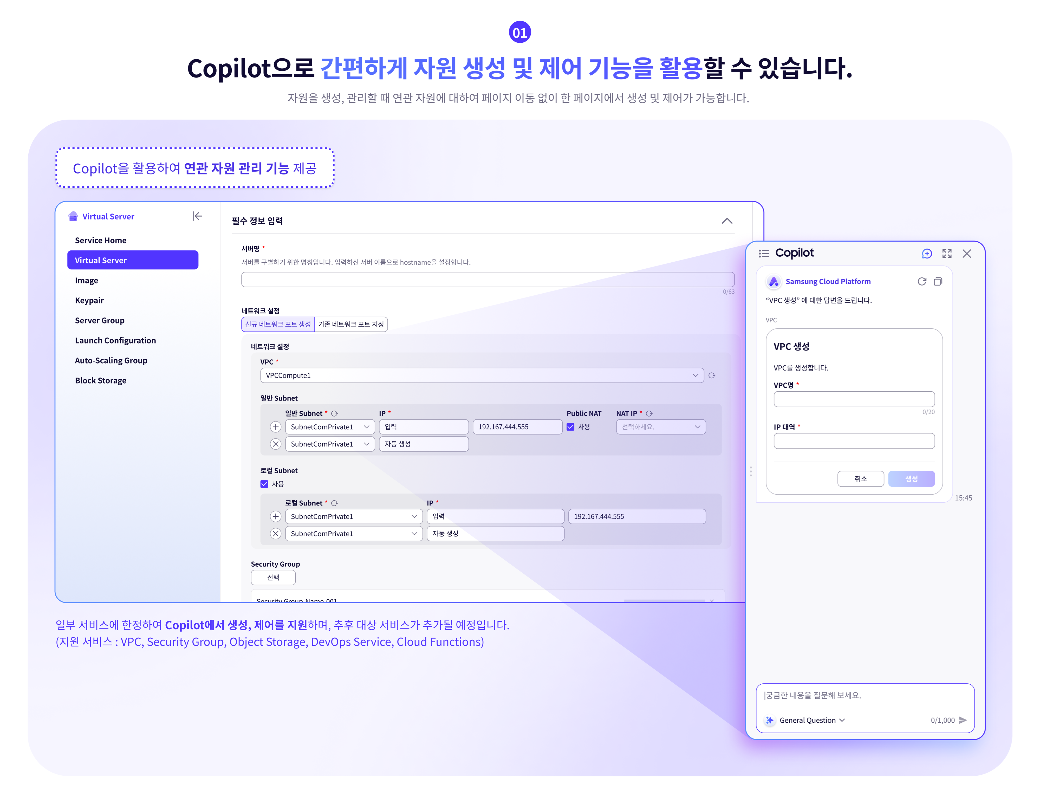
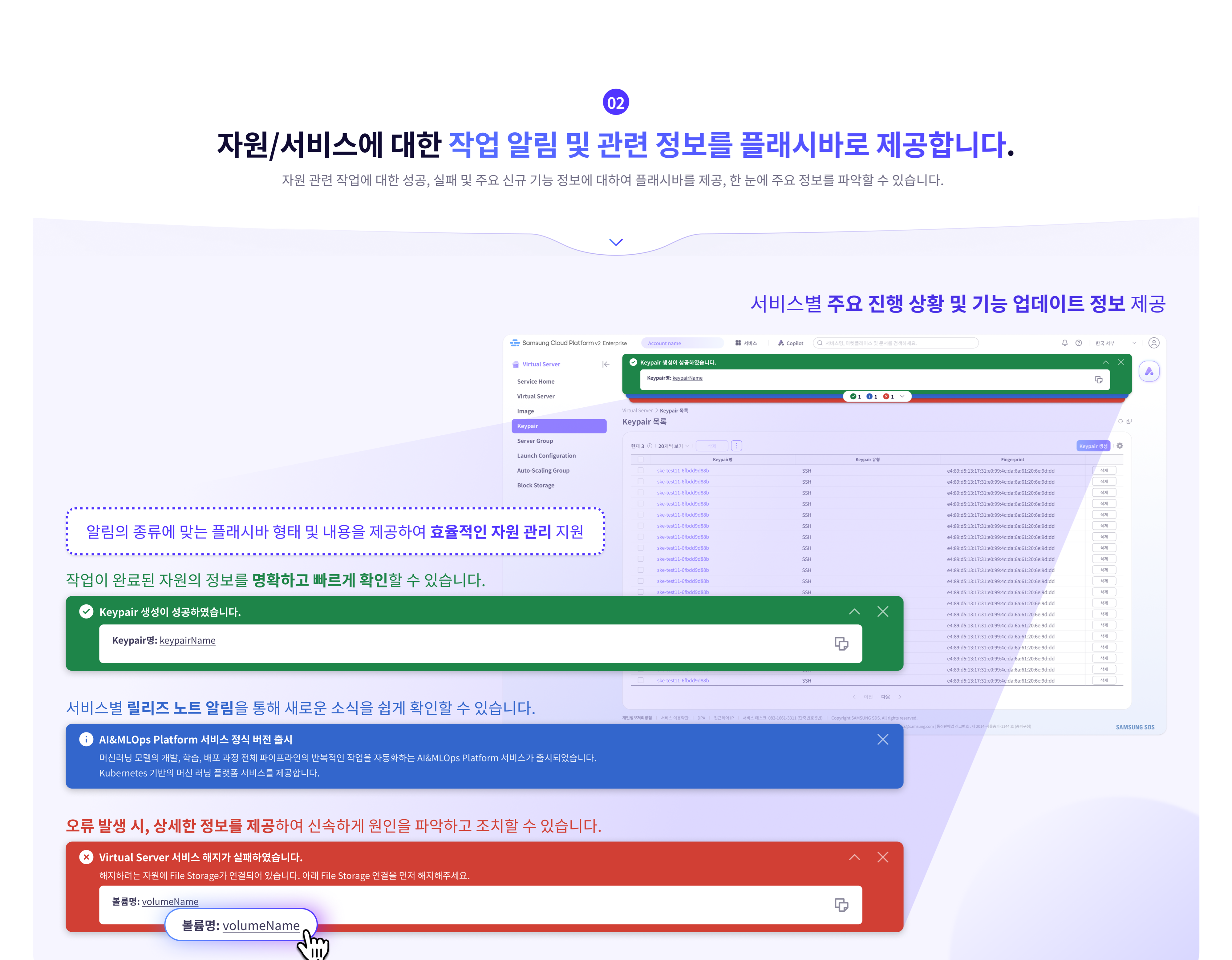
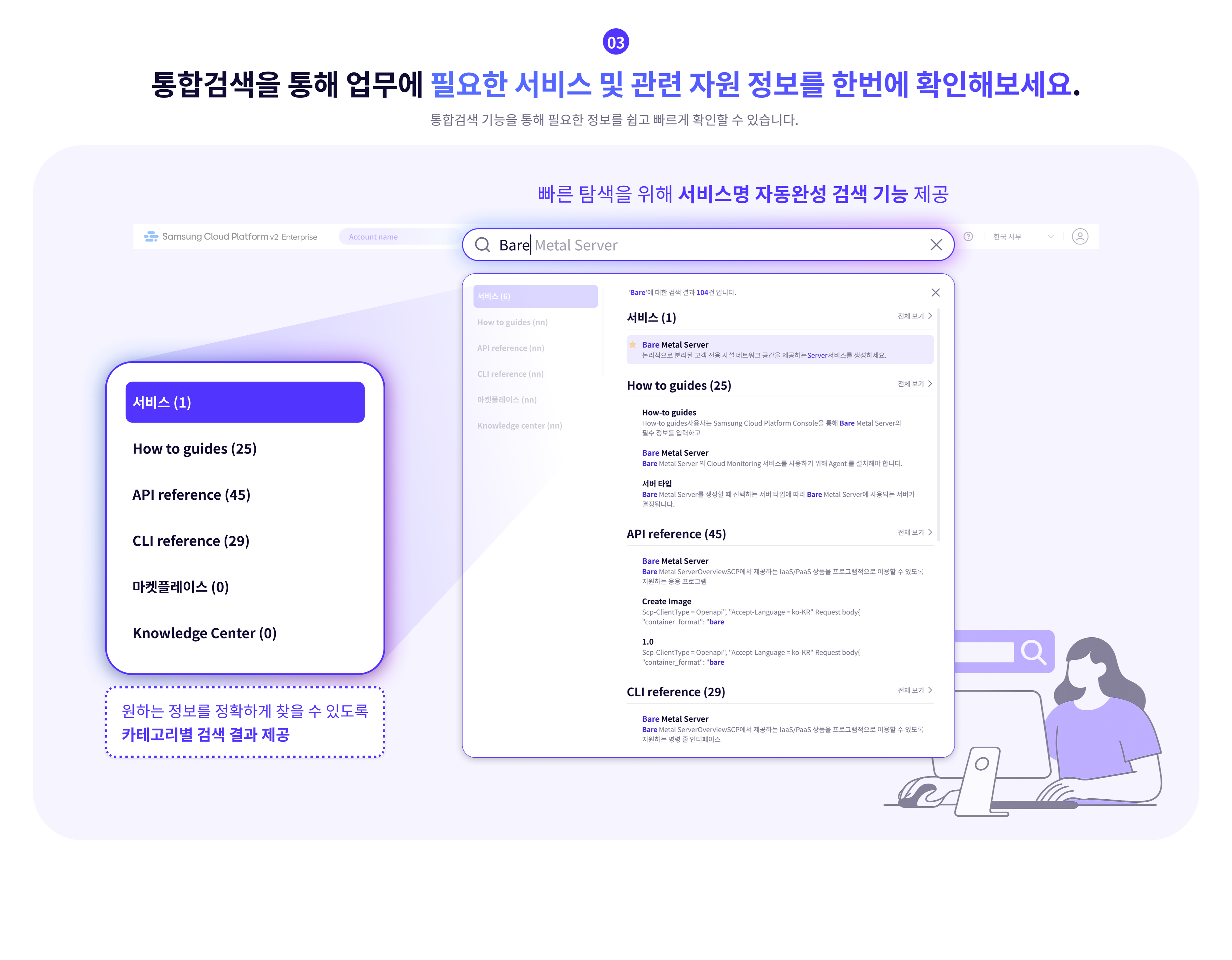
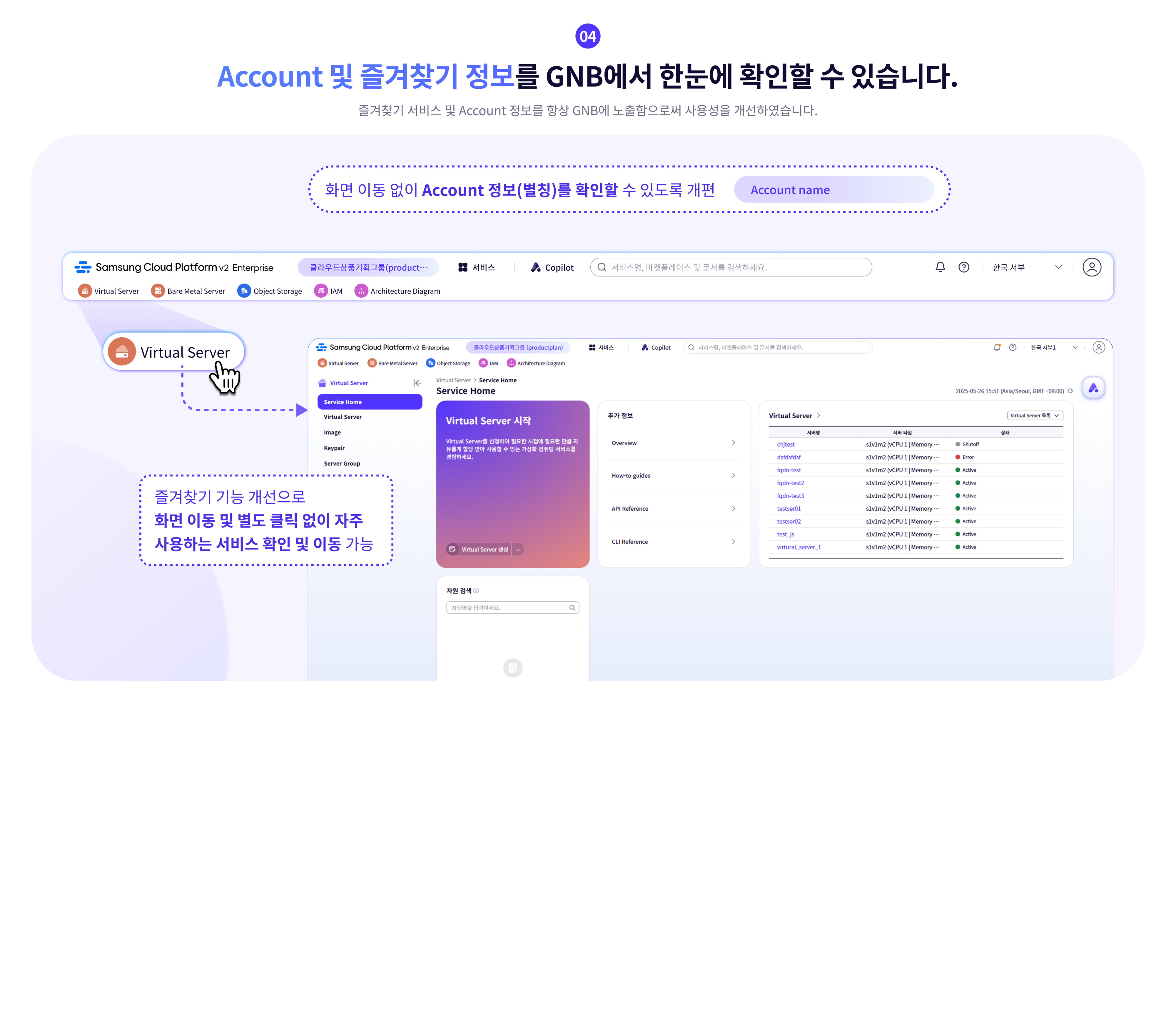
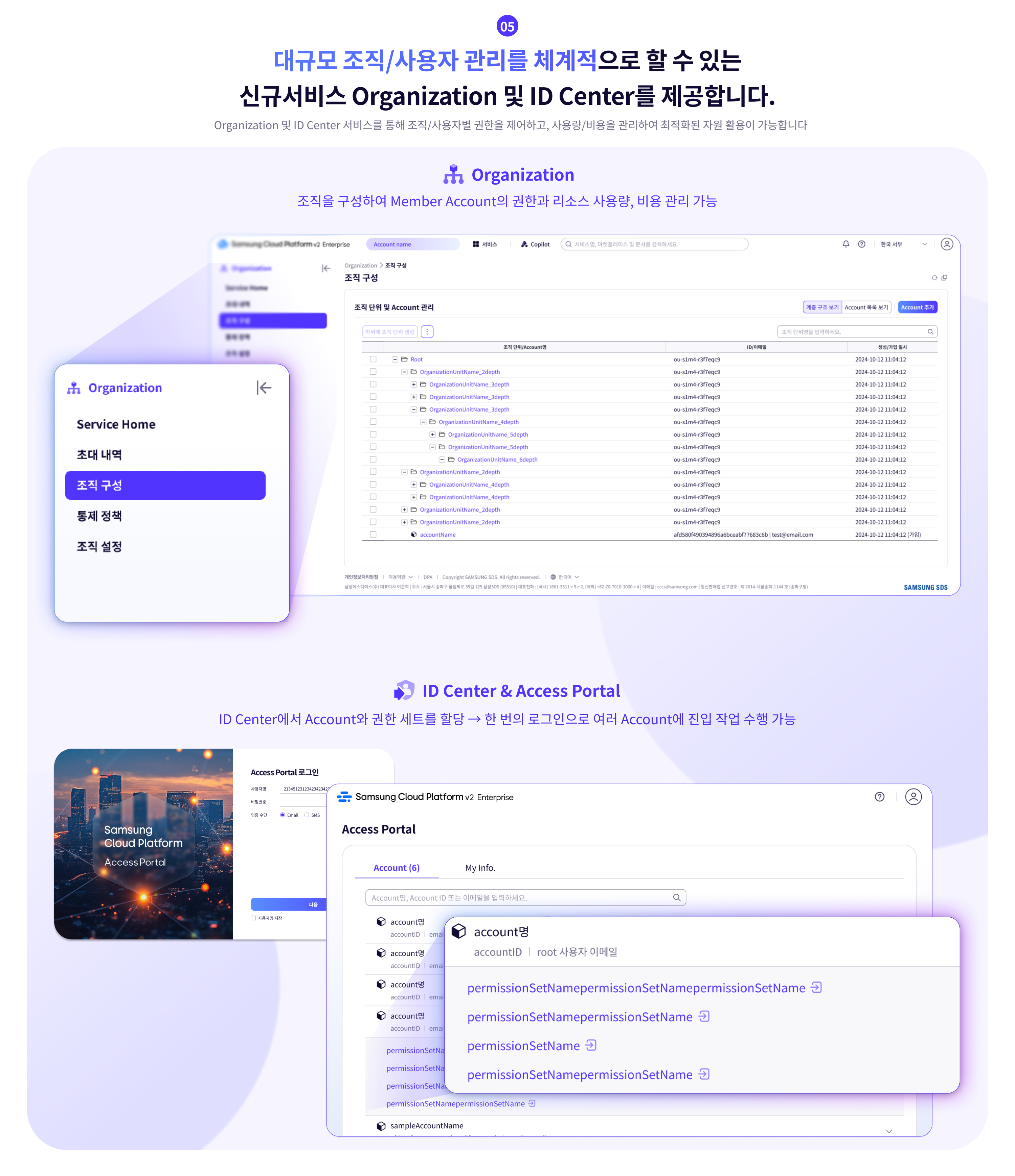
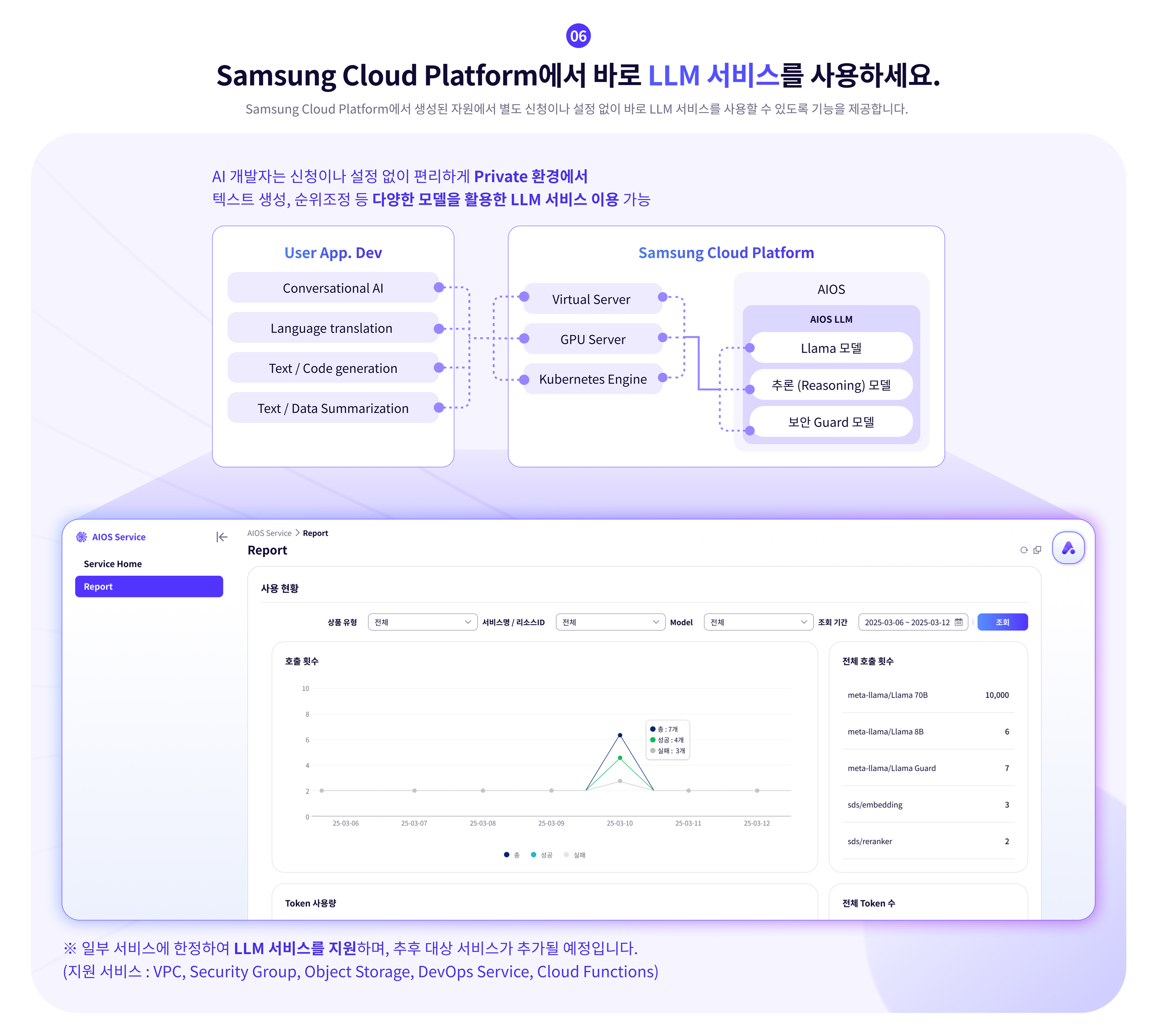
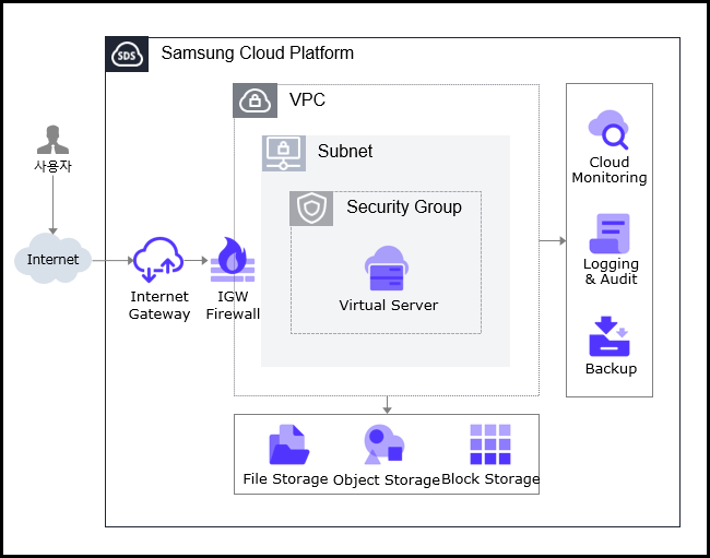
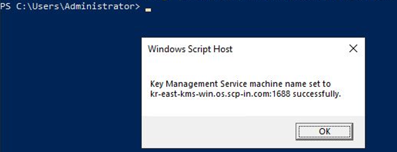
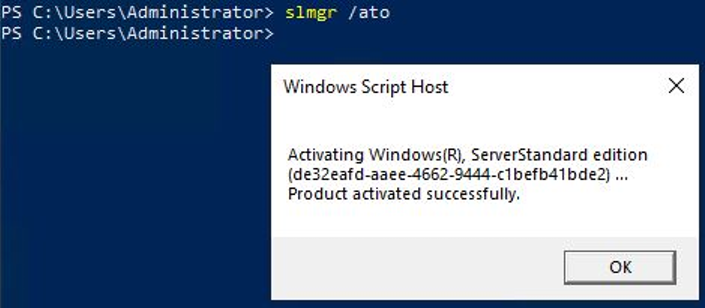
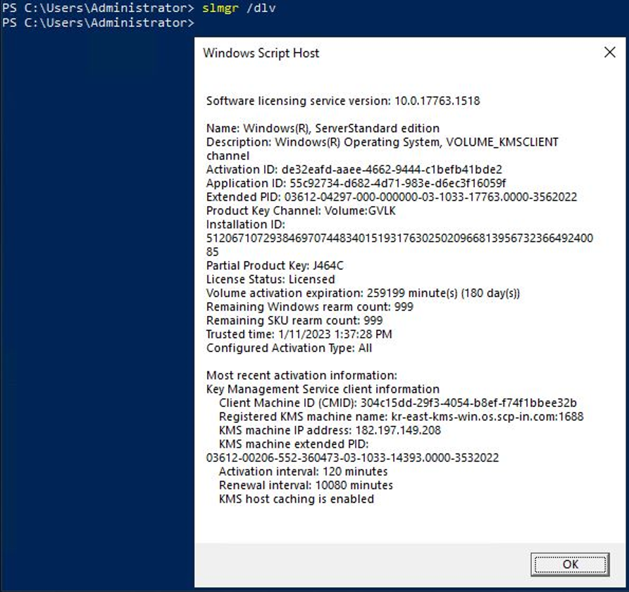
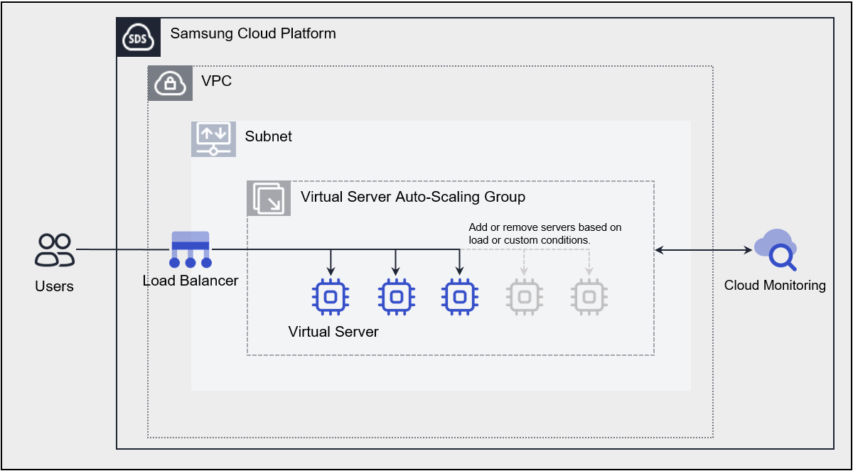
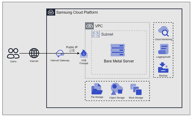


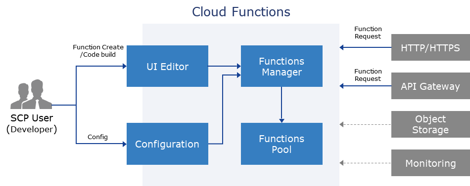
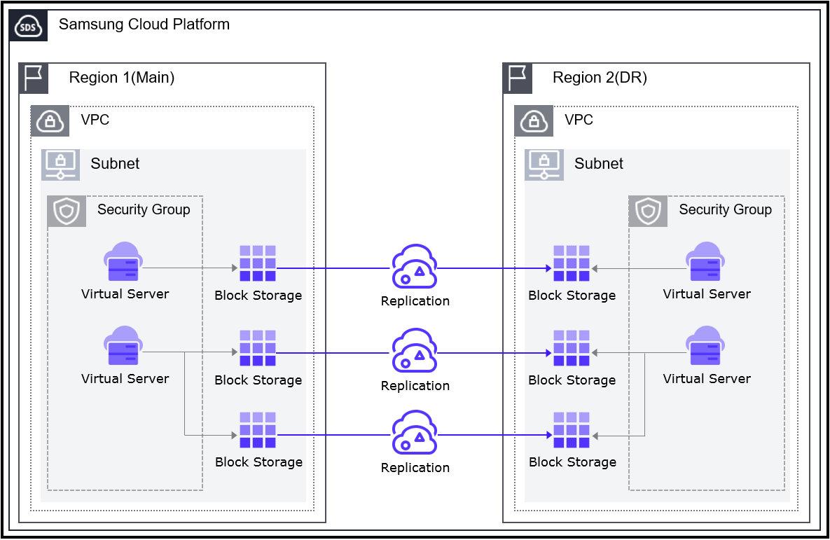
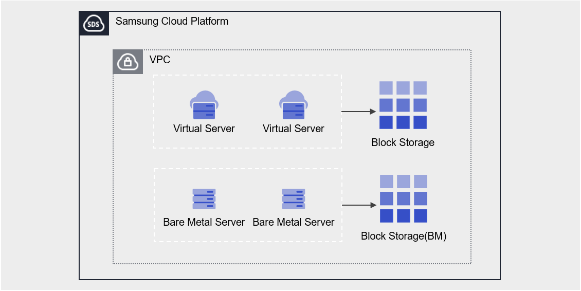
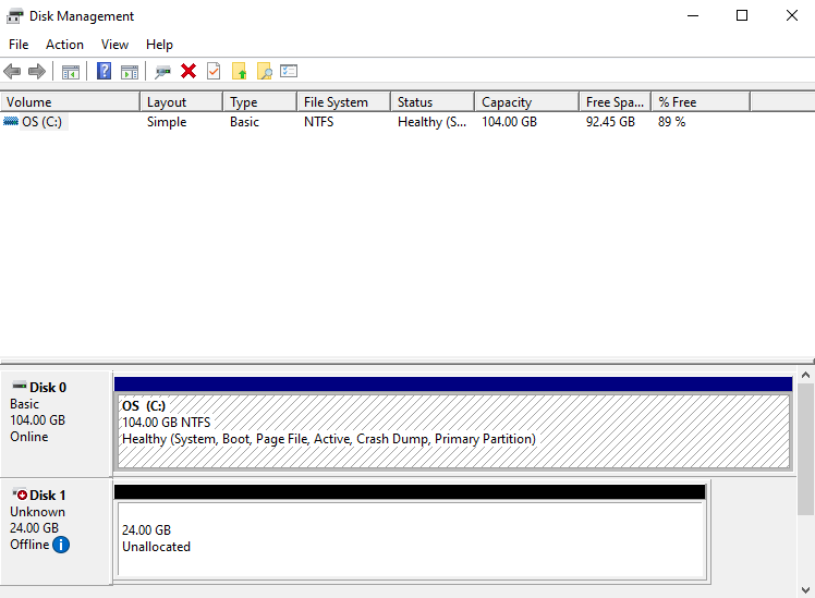

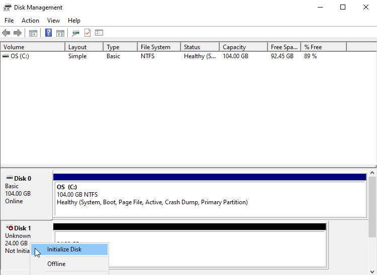
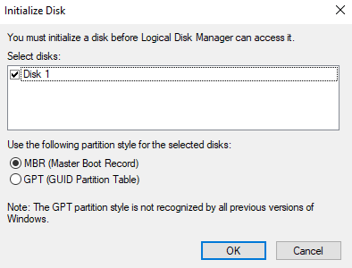
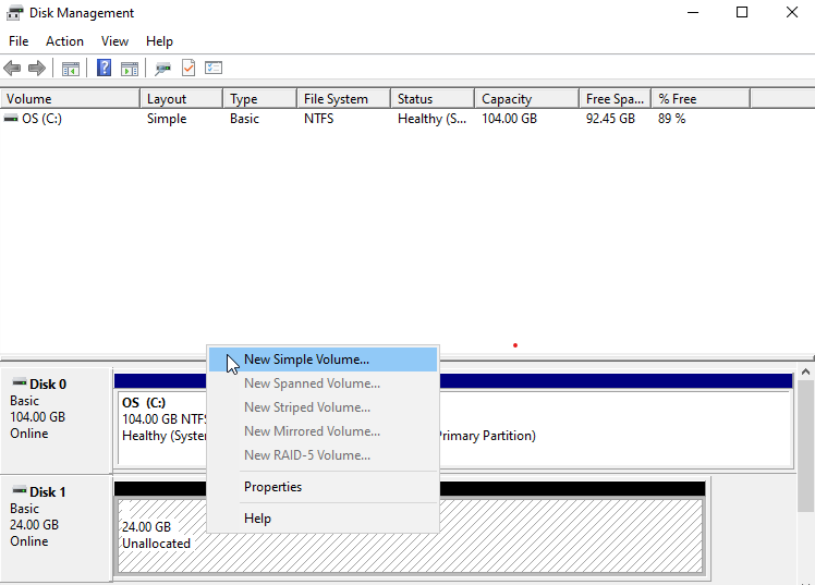
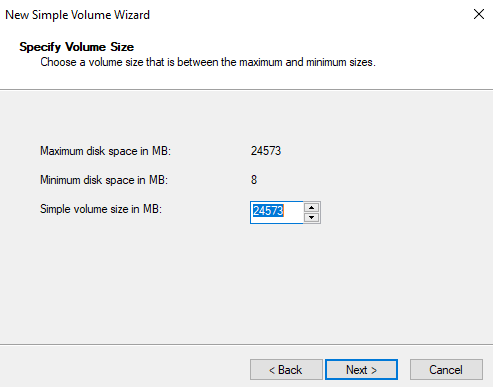
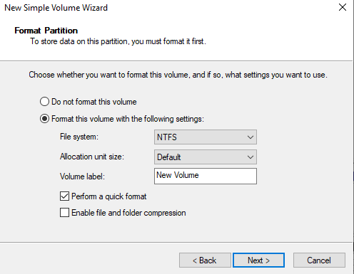
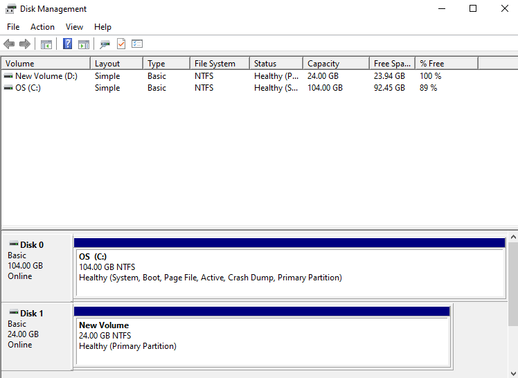
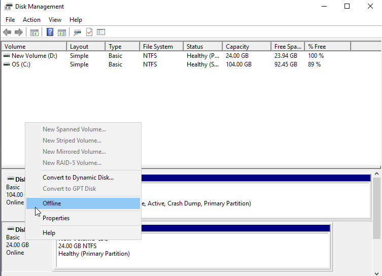


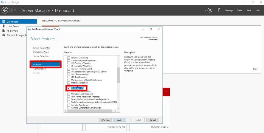
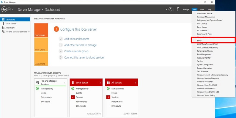
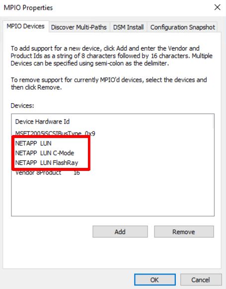
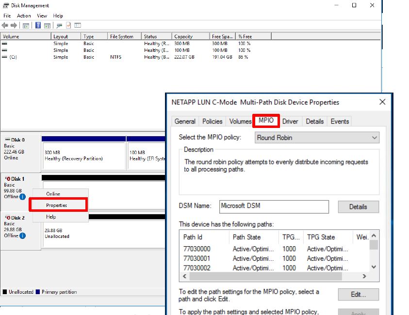

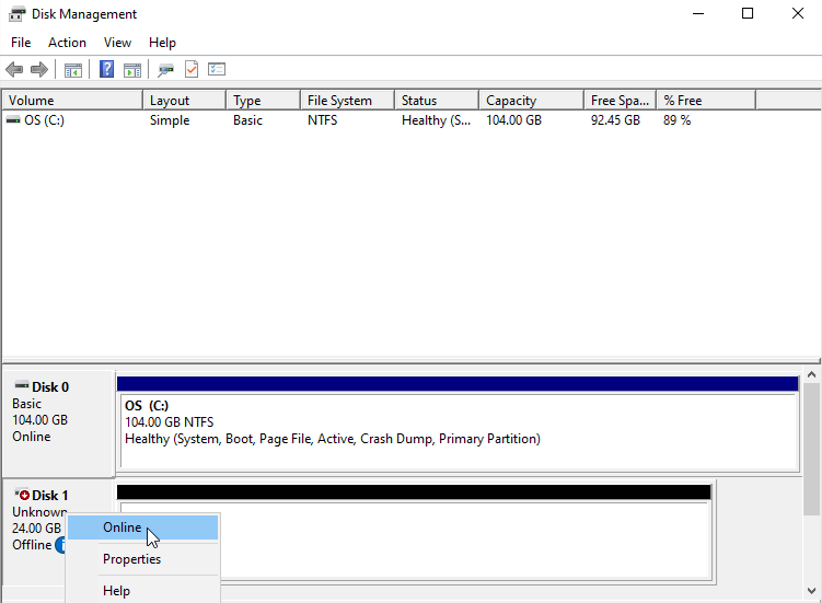


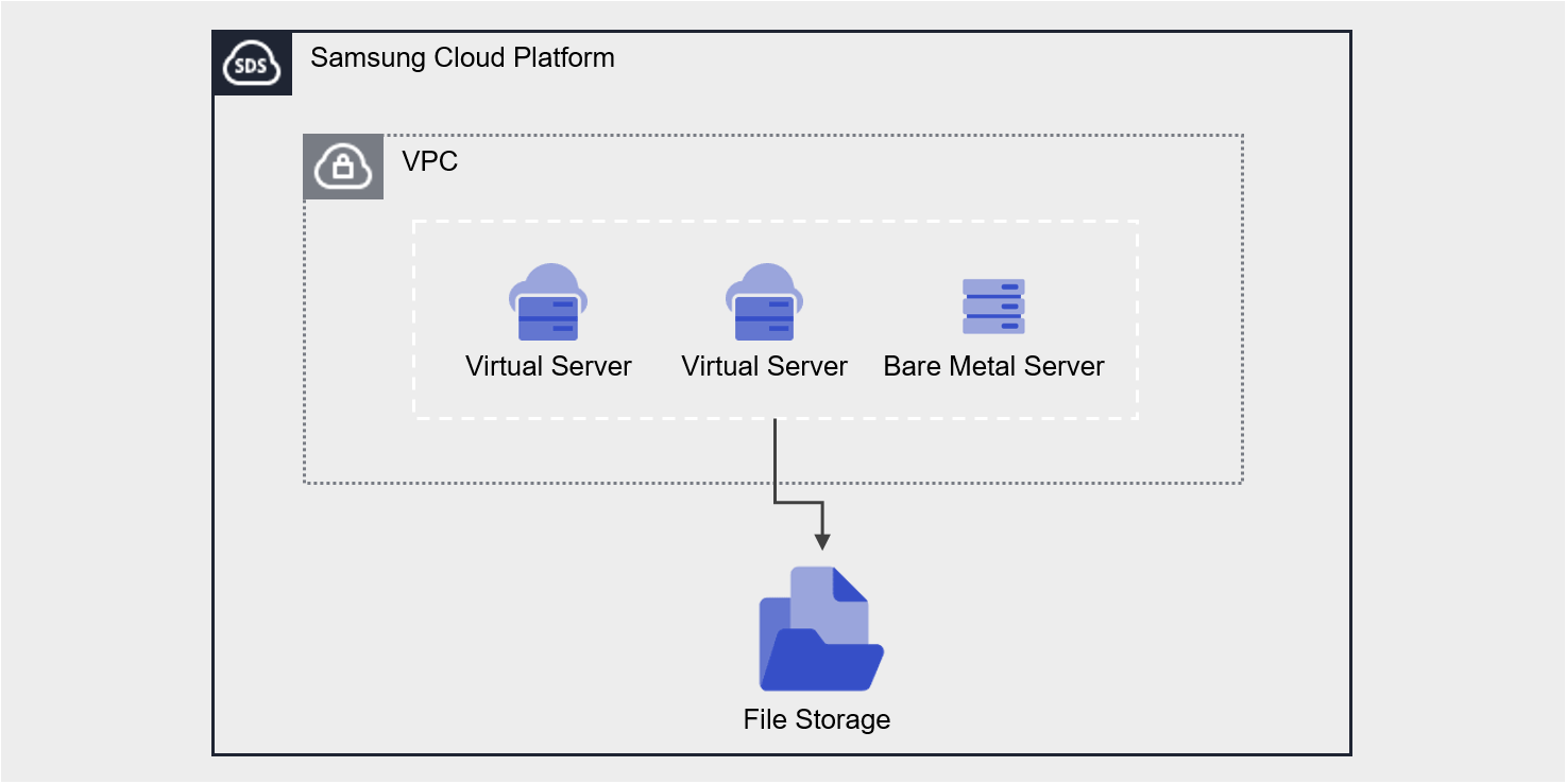
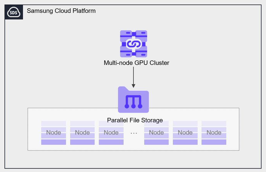
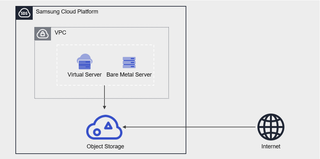
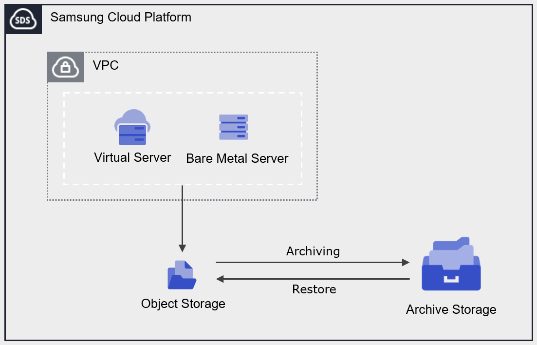
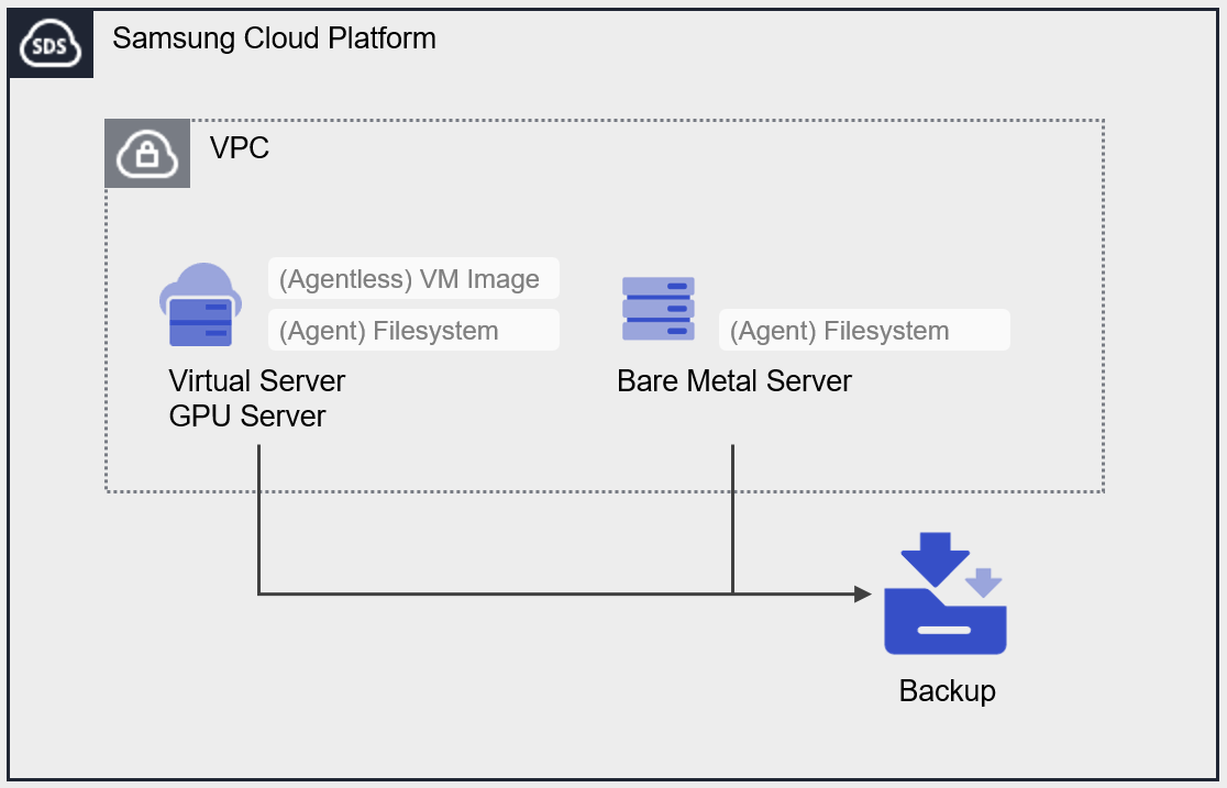
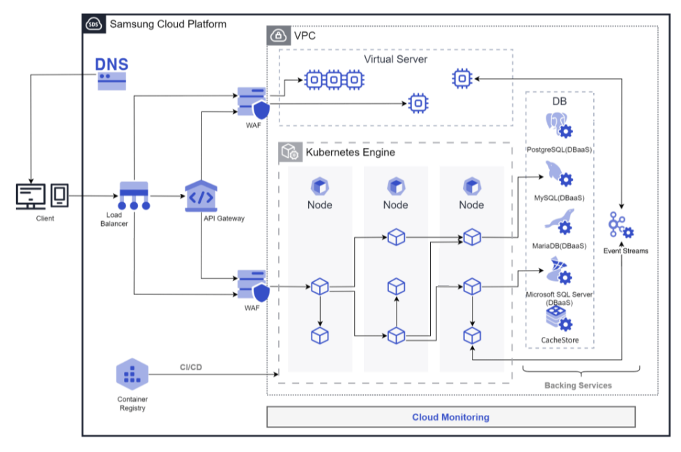
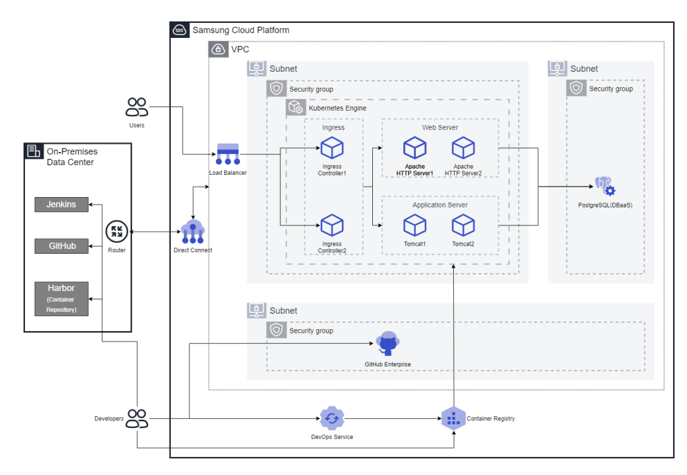
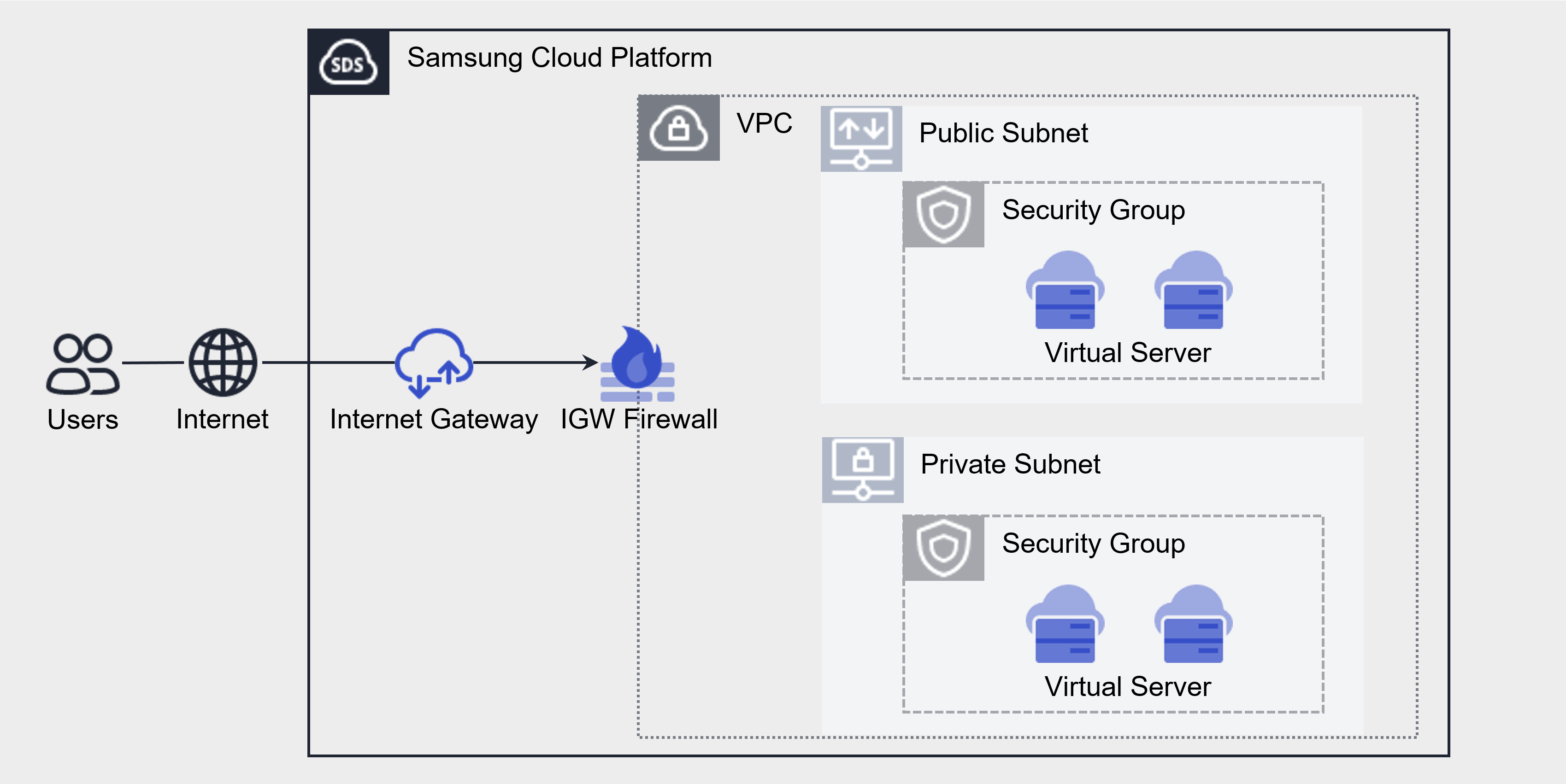
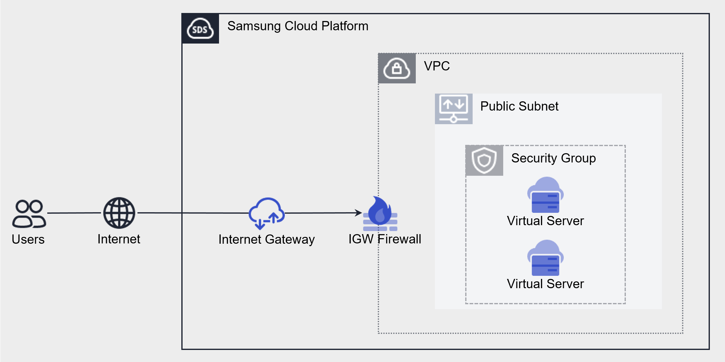
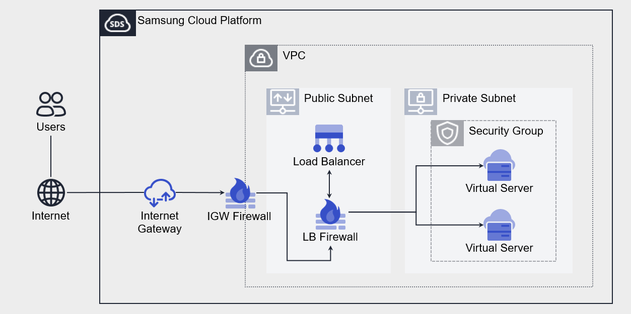
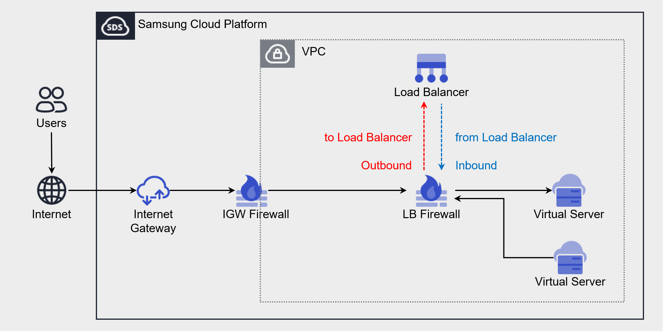
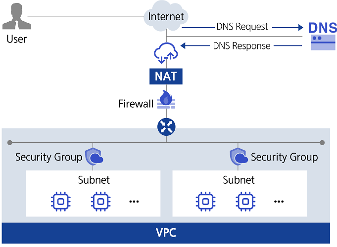
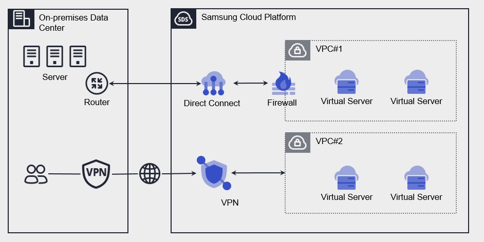
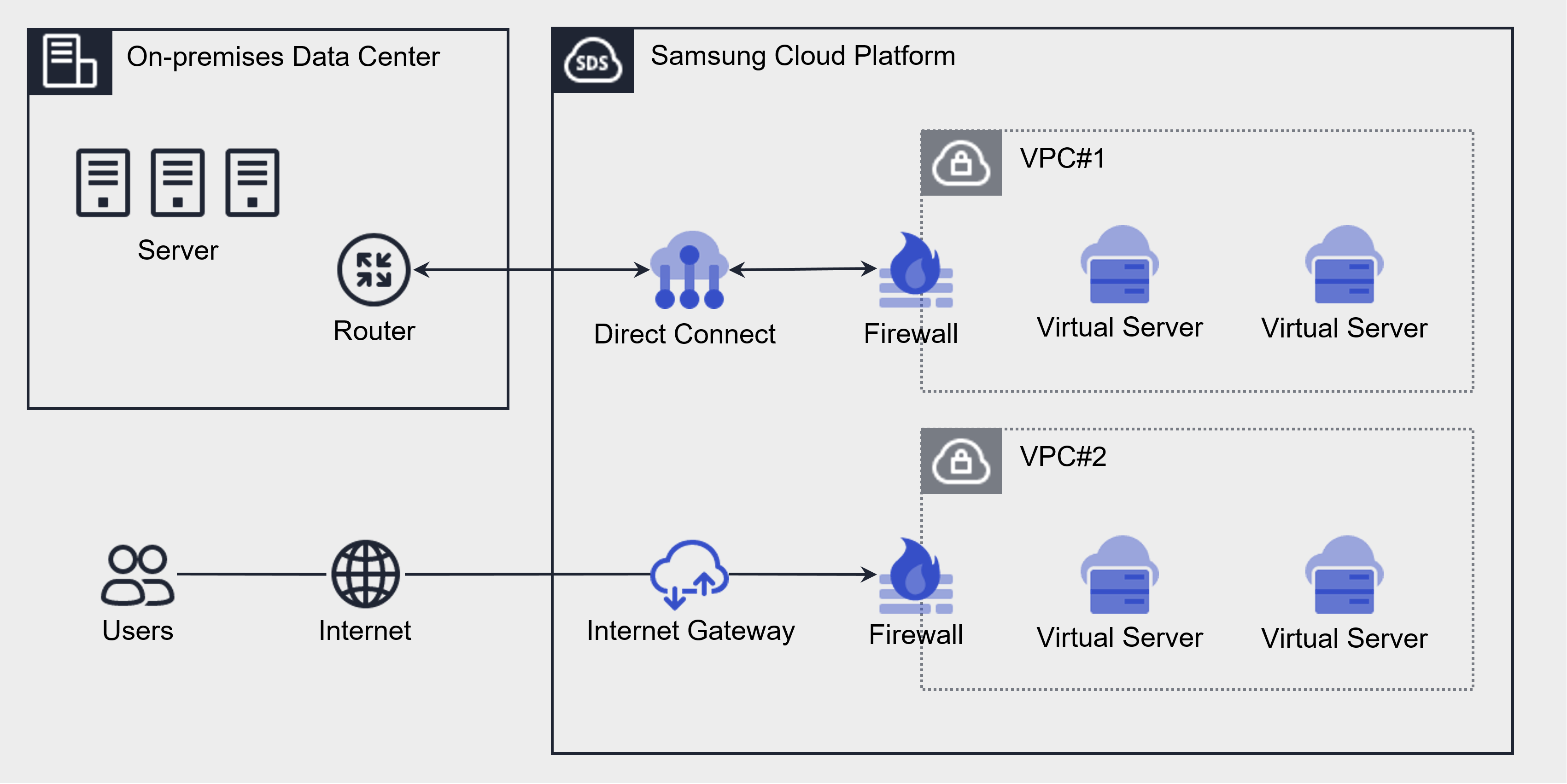
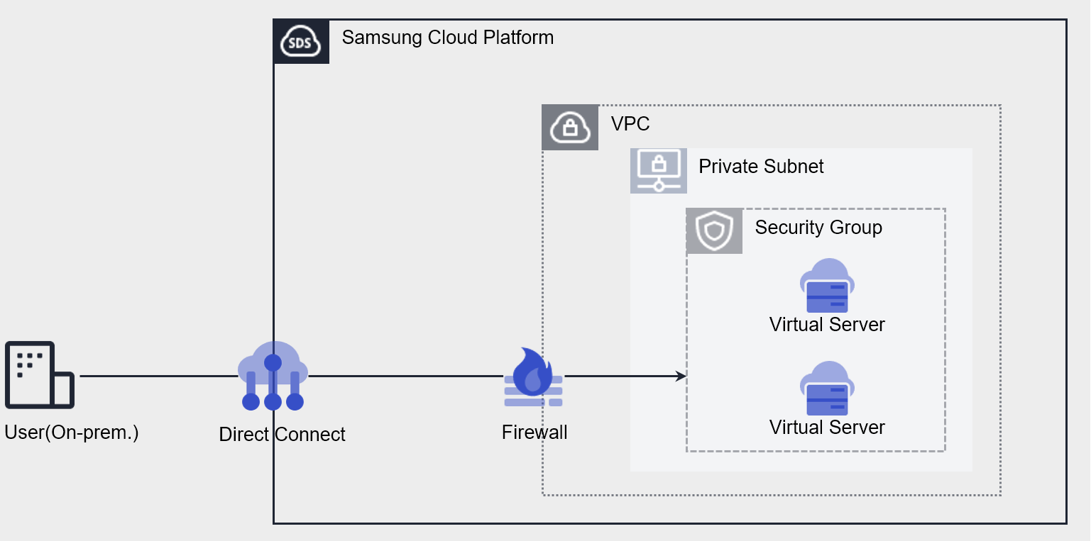
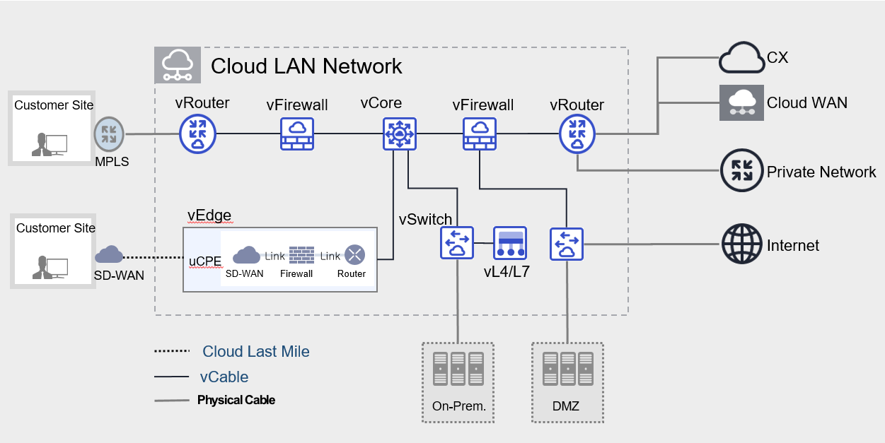
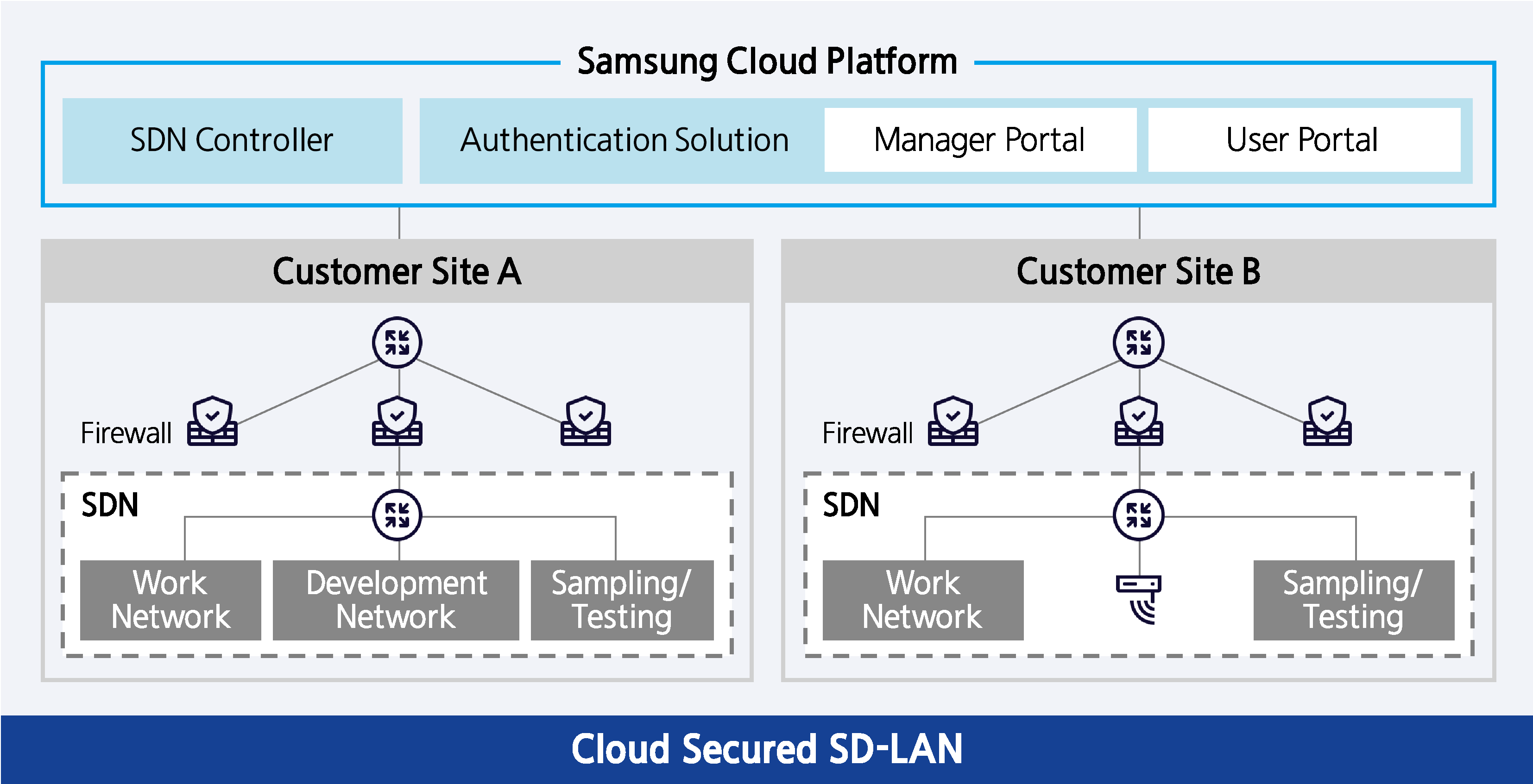
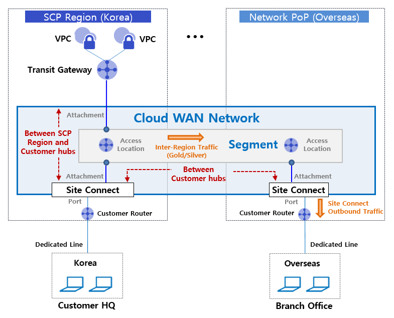
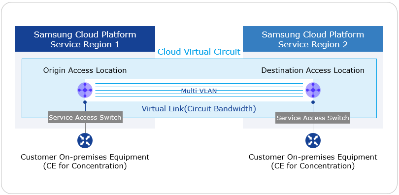
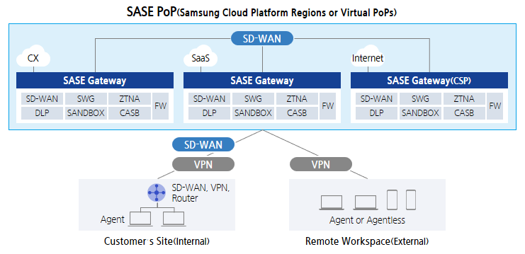
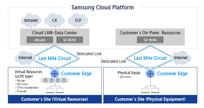
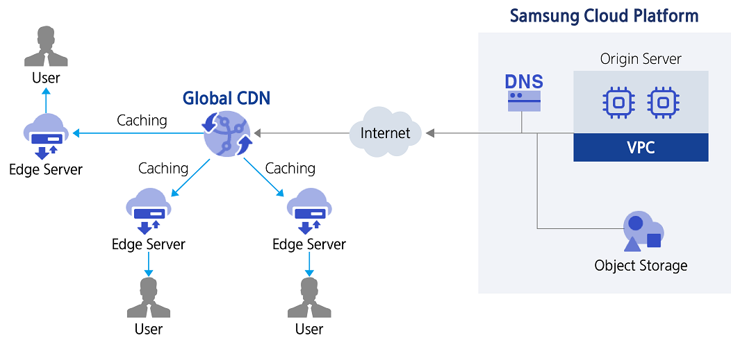
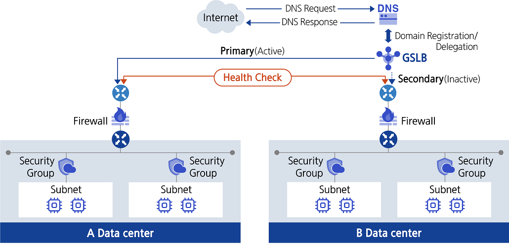
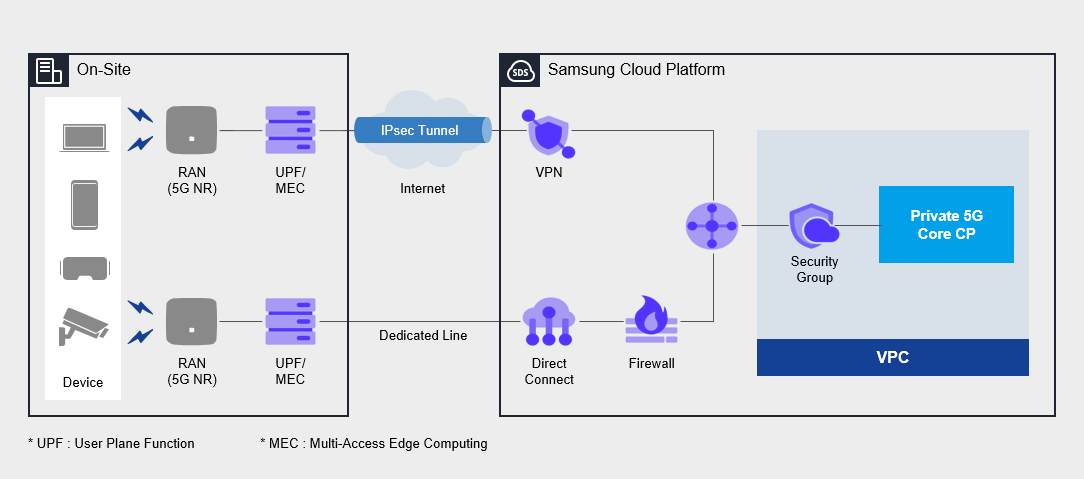
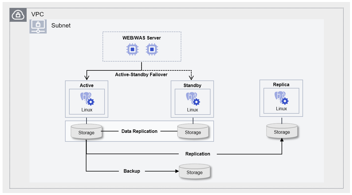
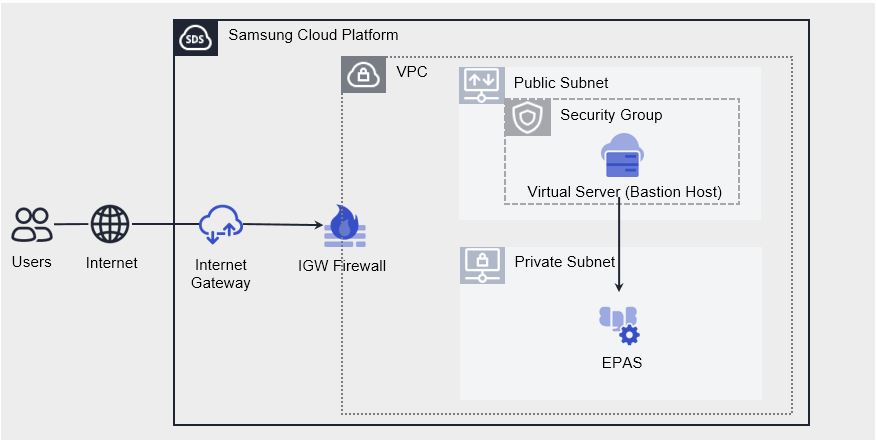
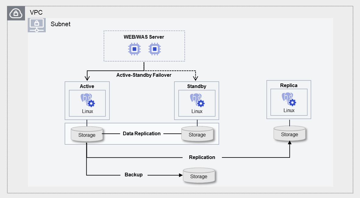
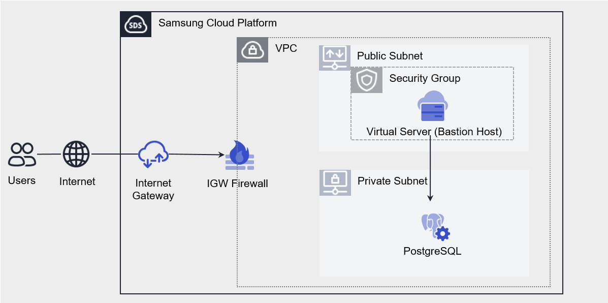

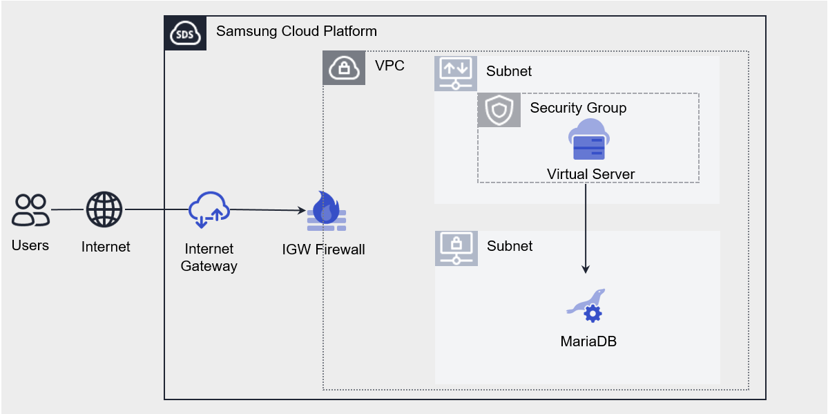

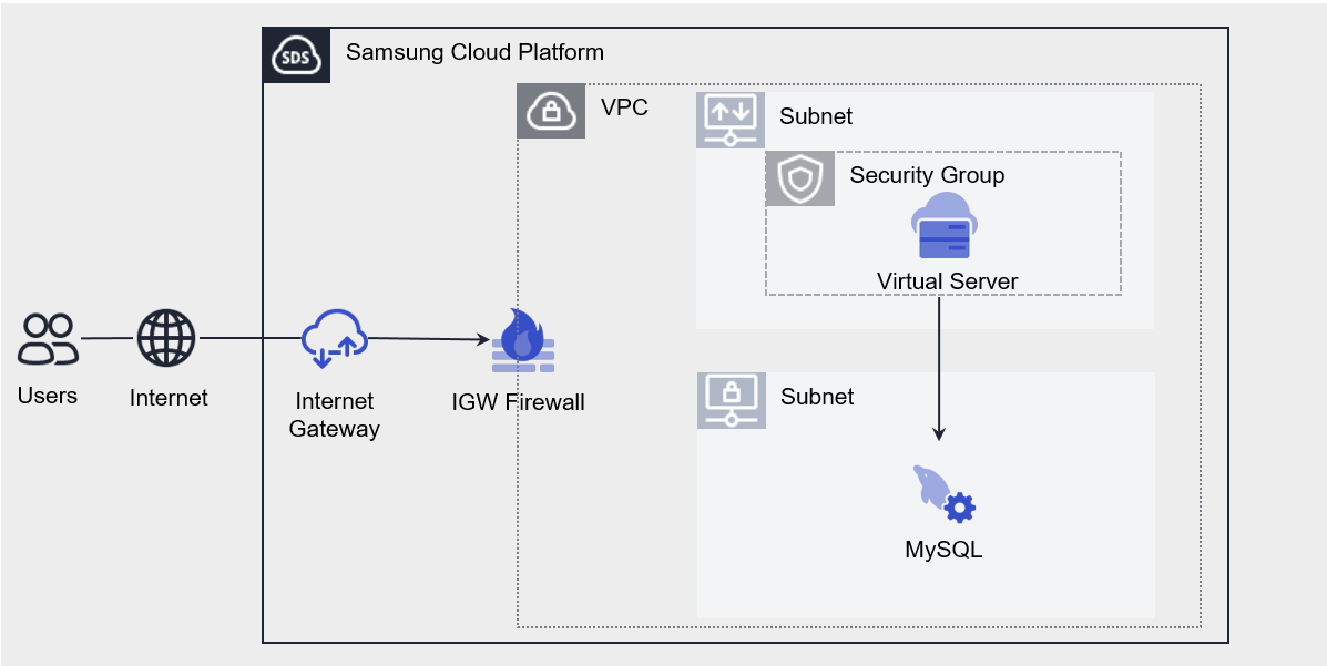

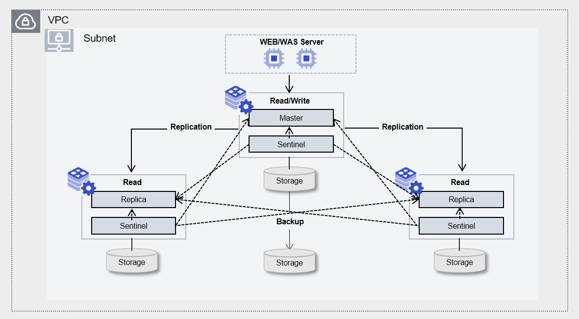
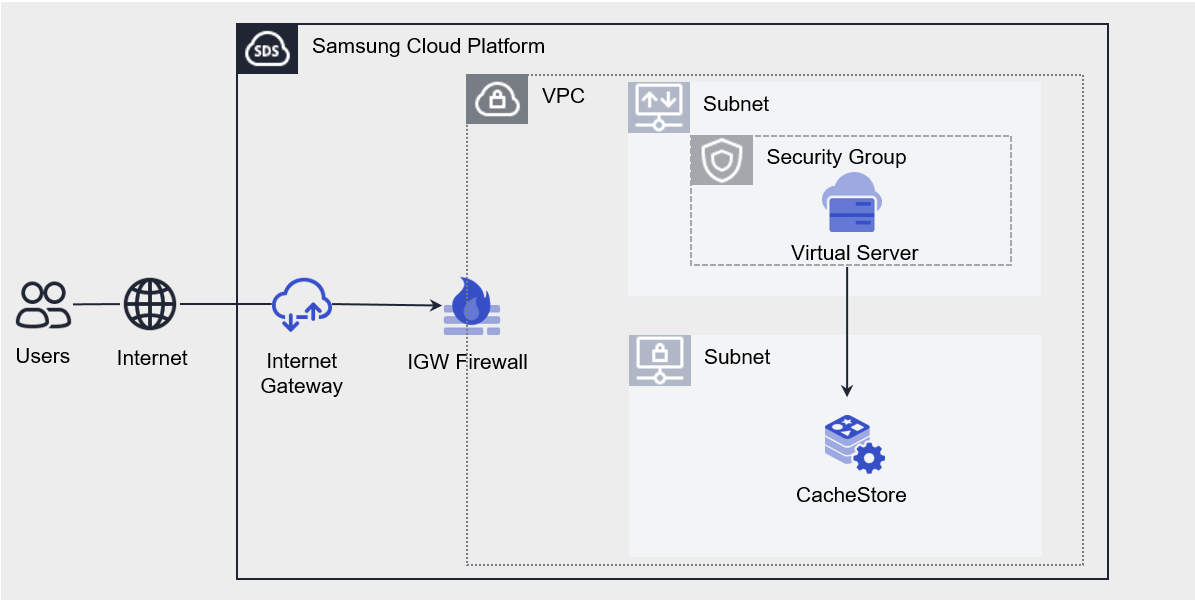
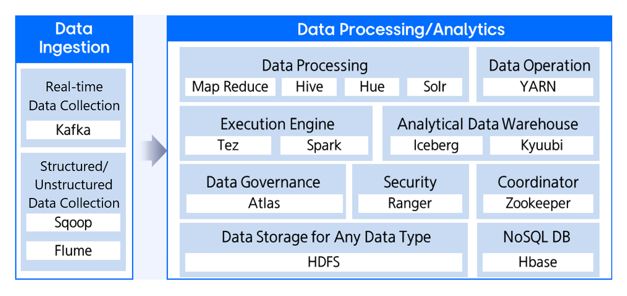
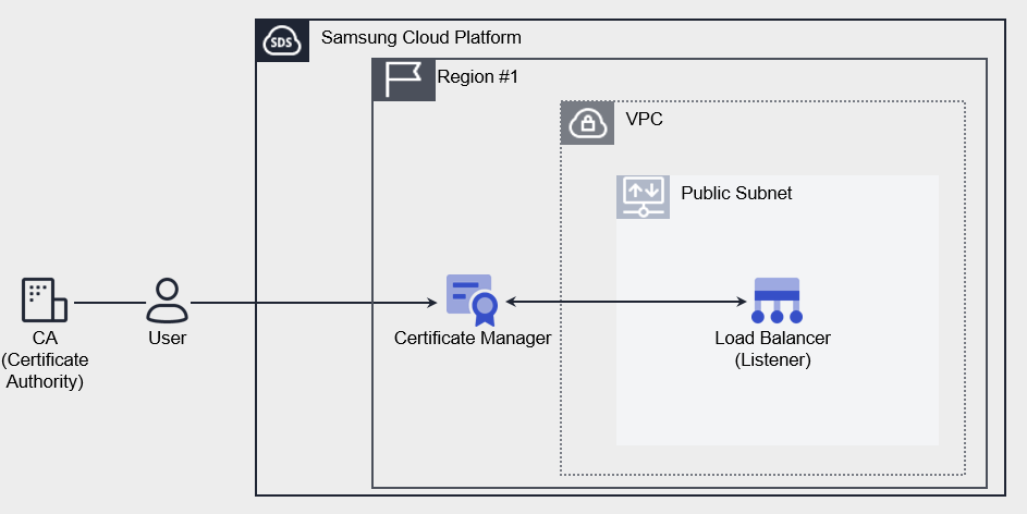
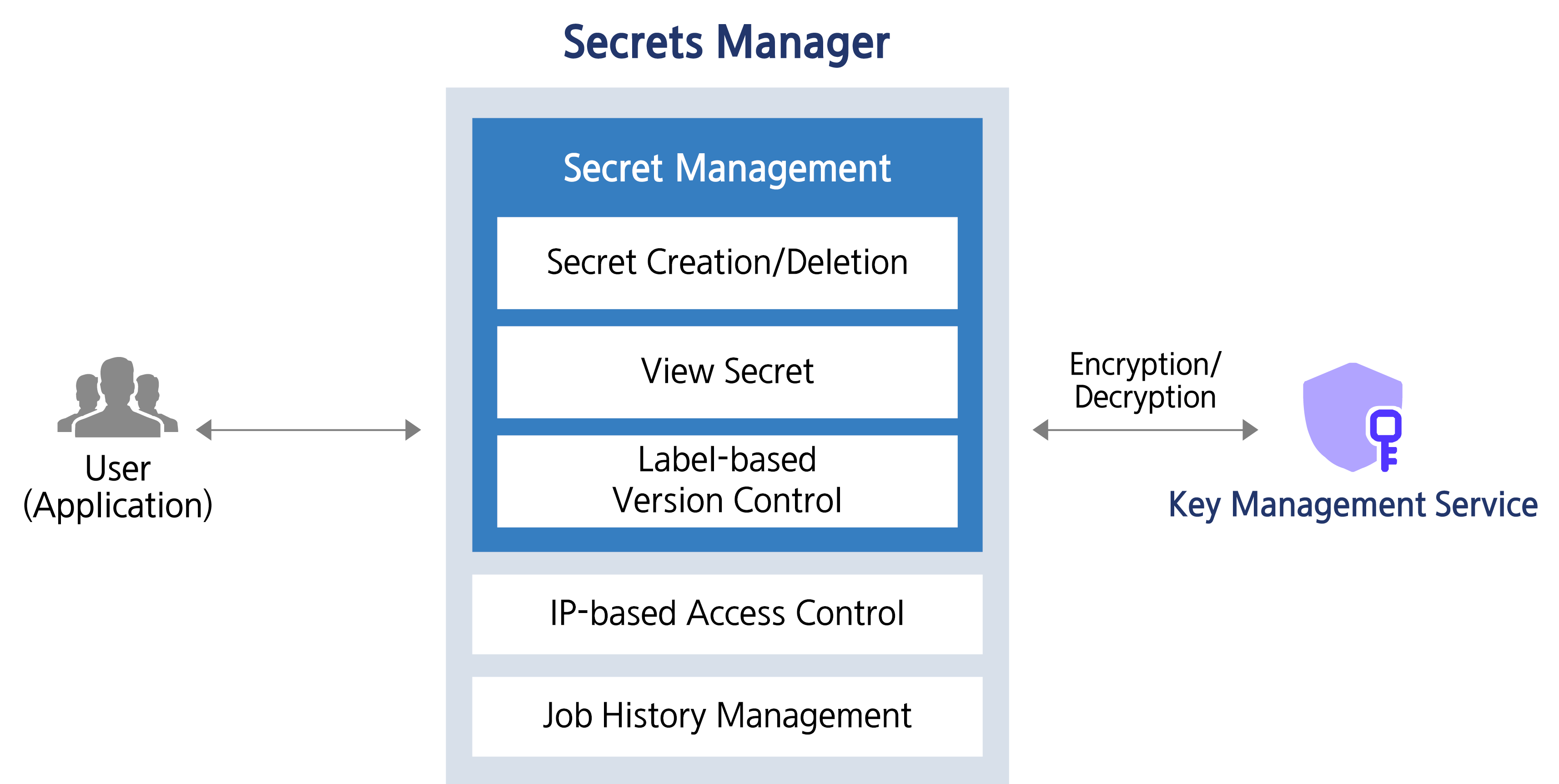
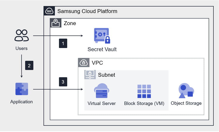
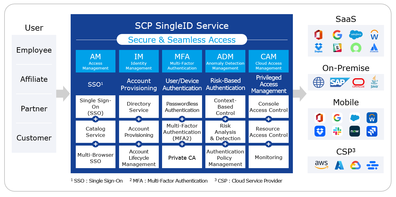
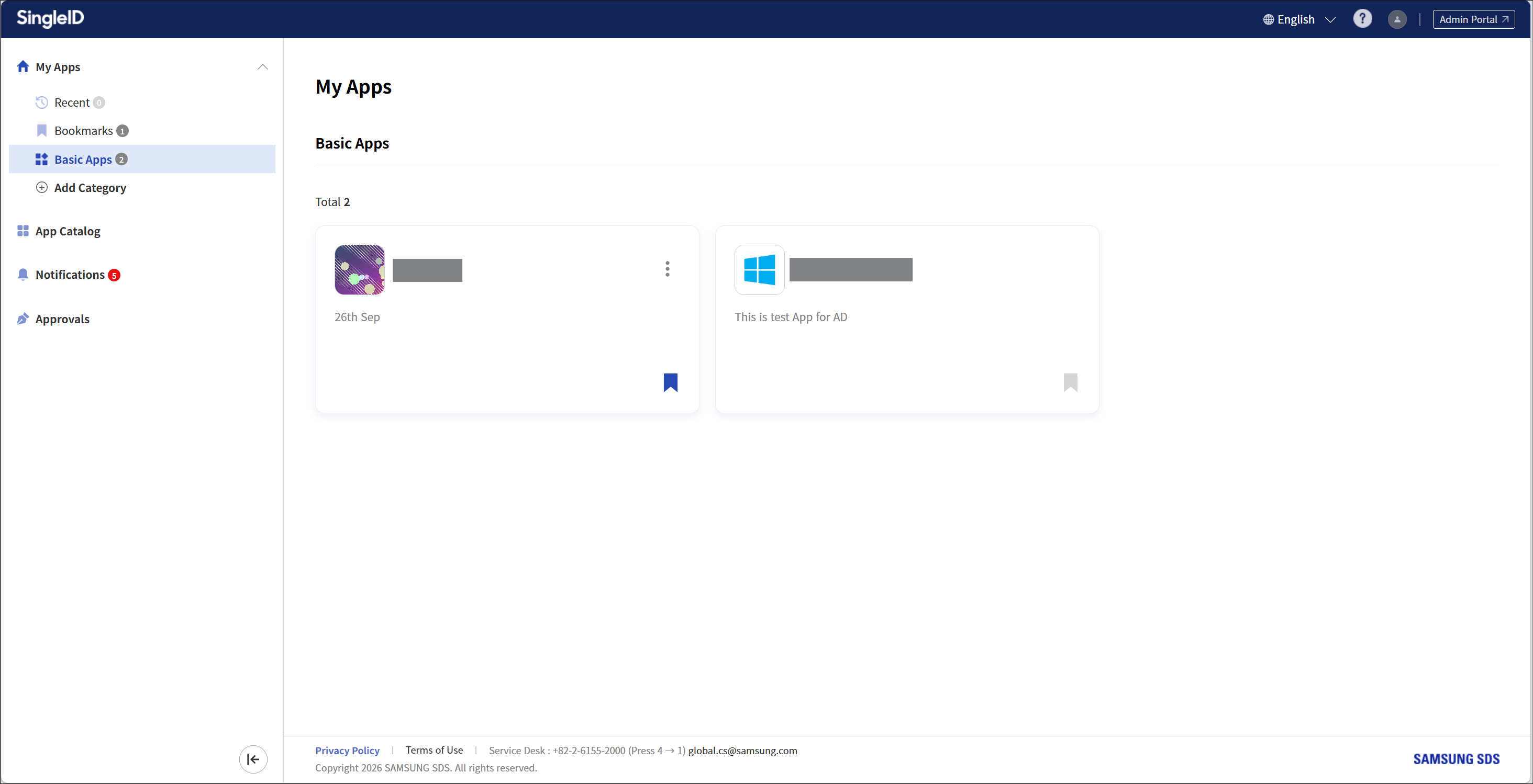
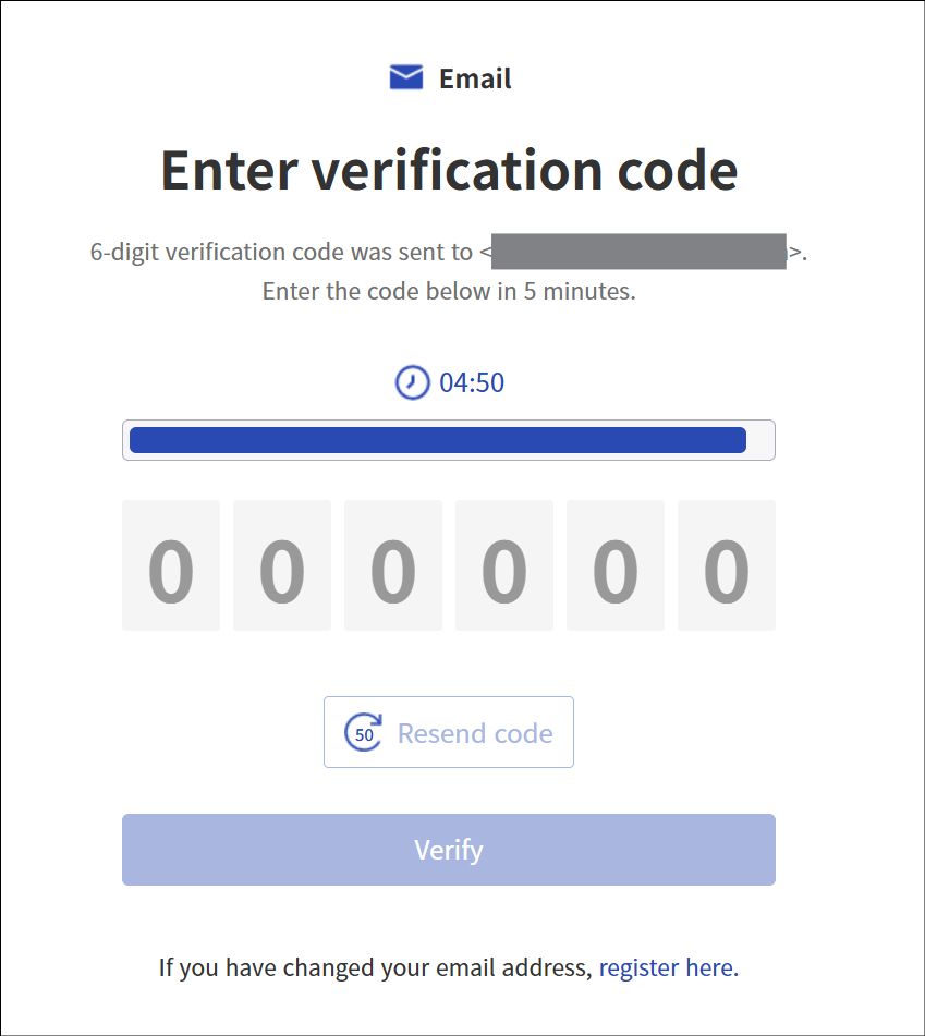


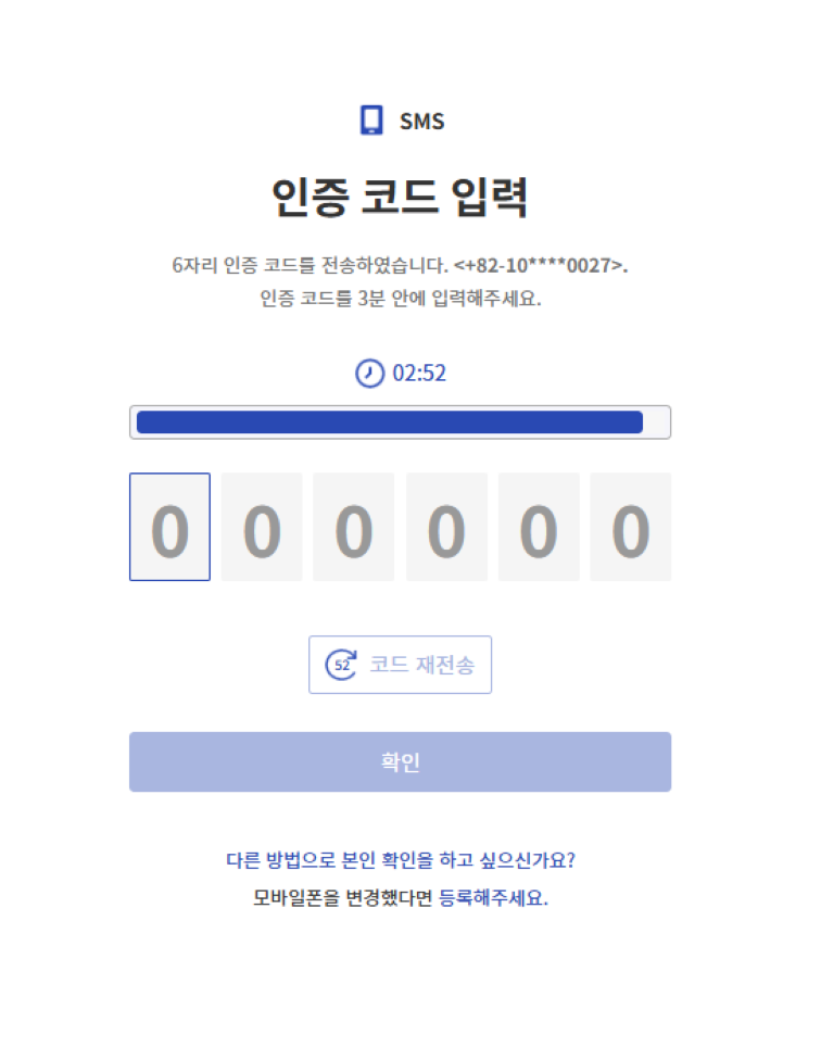
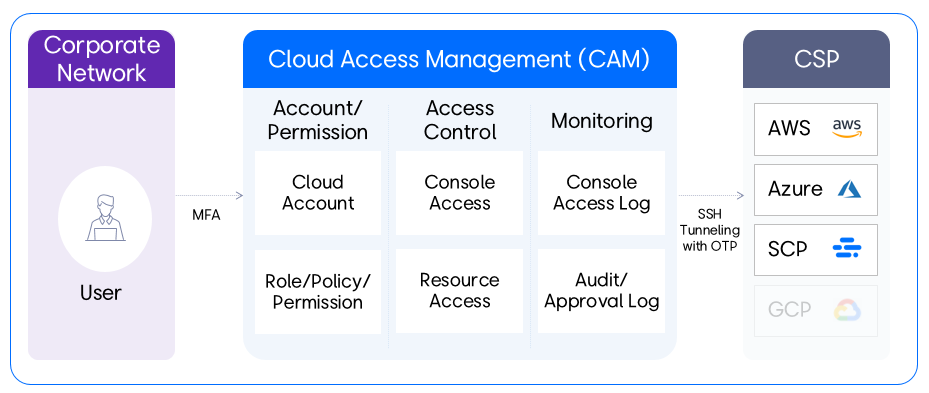
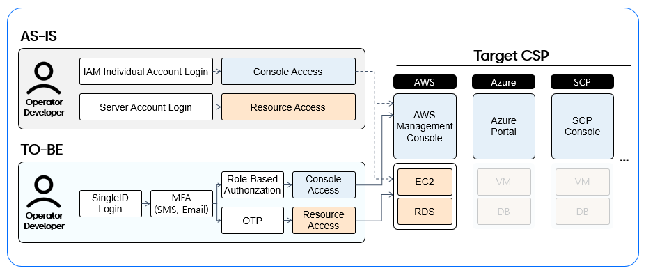
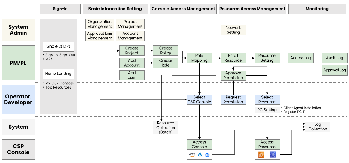
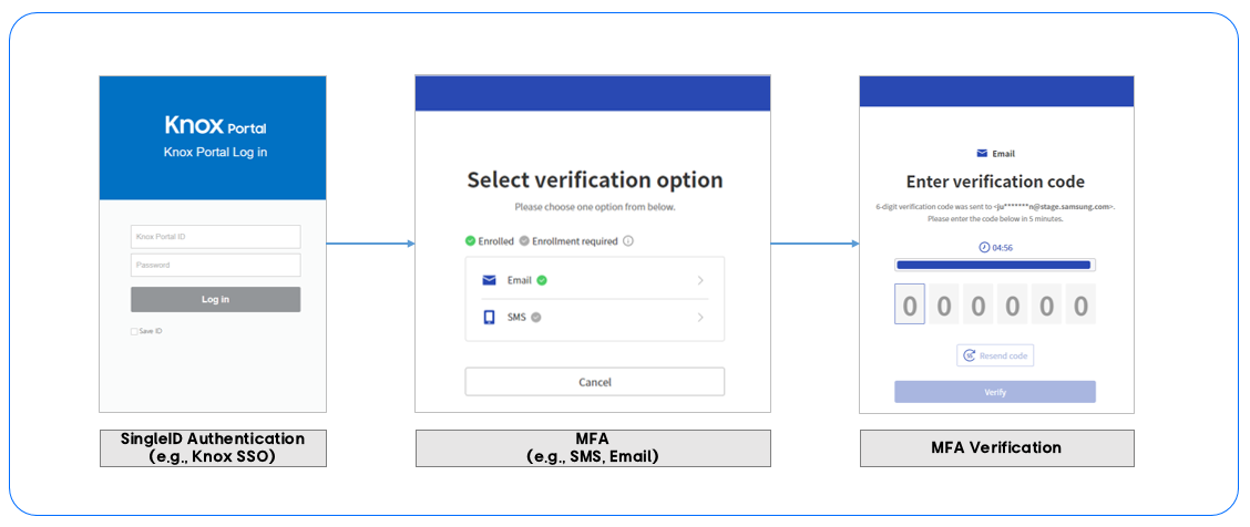
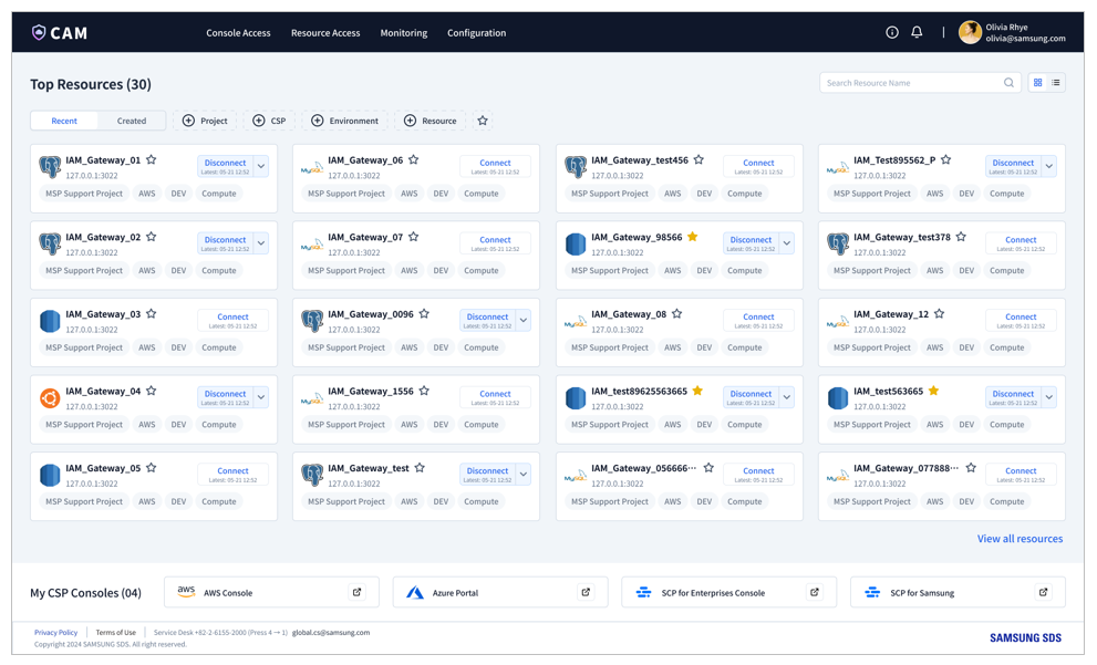

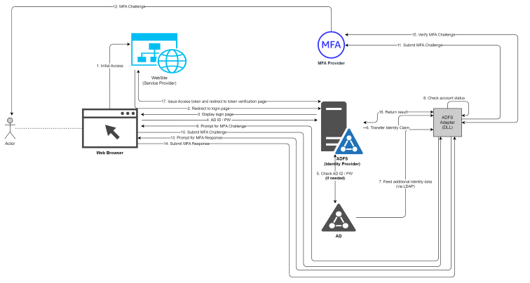
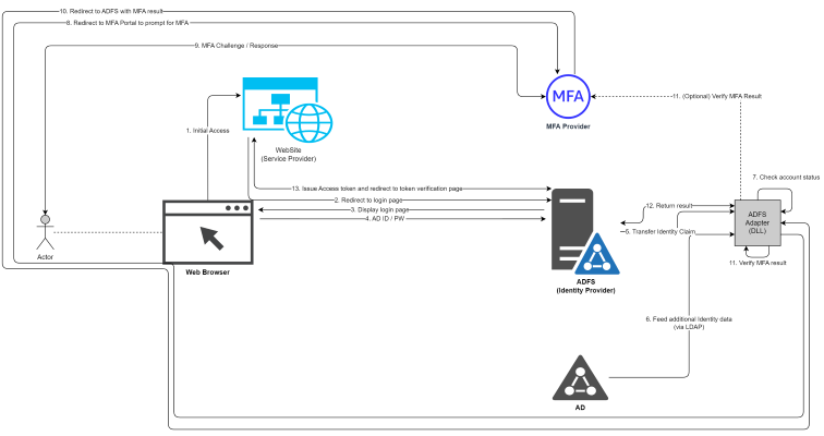
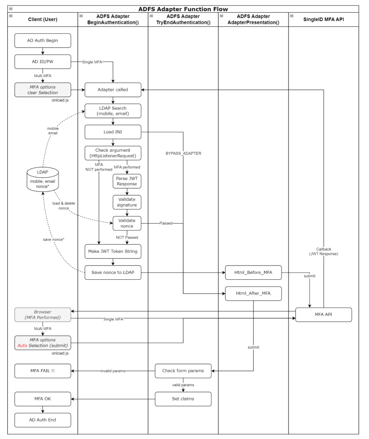
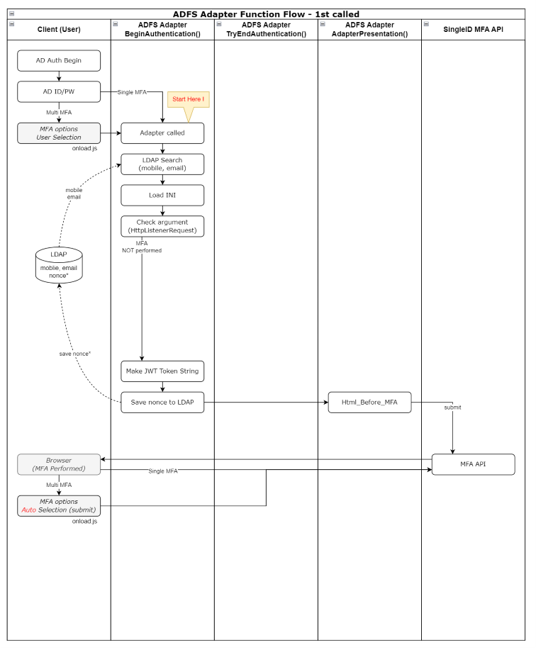
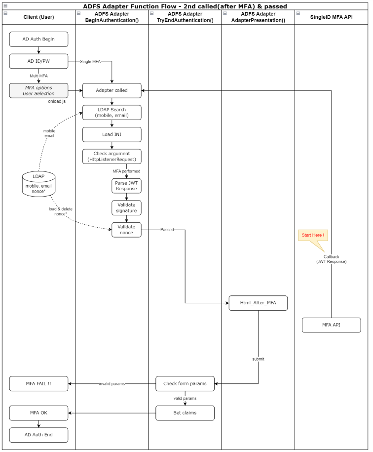
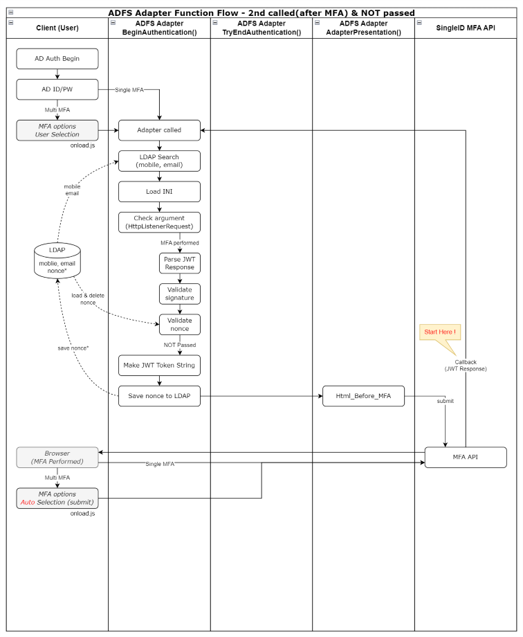
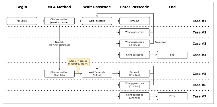
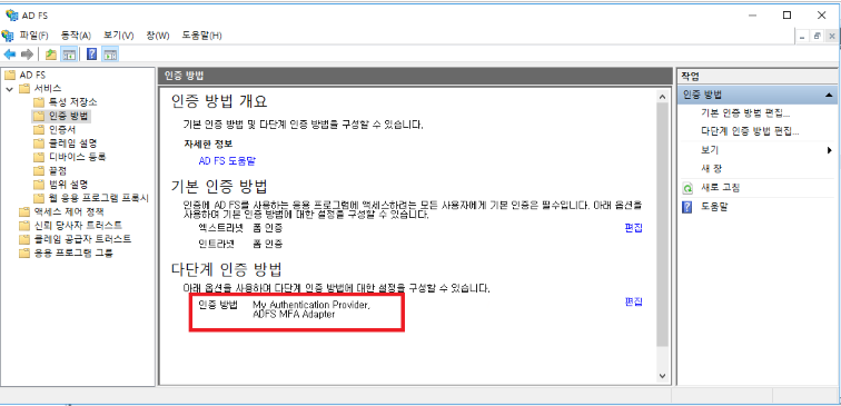

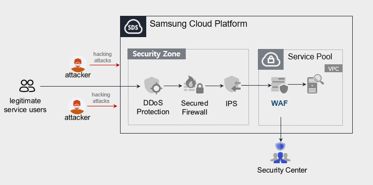
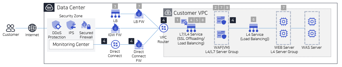
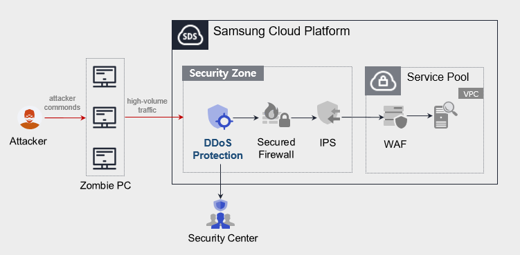
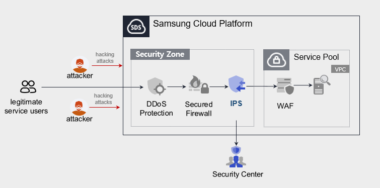
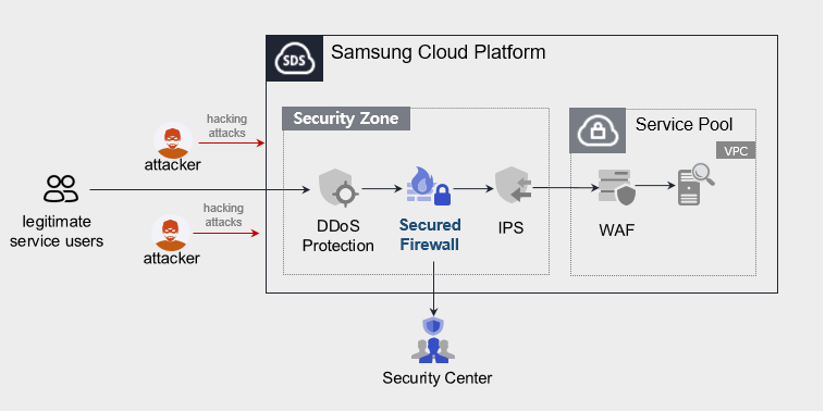
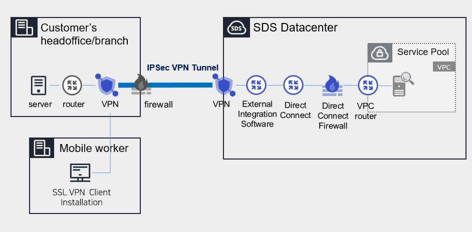
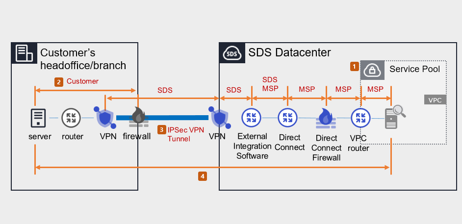
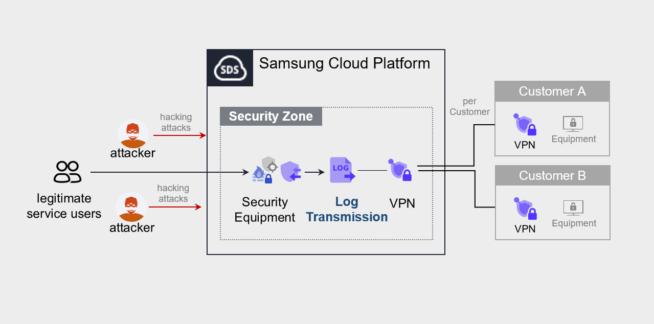
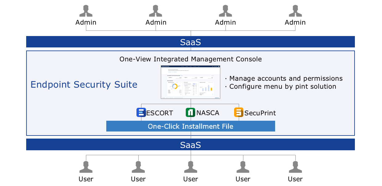
 유형")
 유형")