Disaster Recovery Planning
Architecture Design According to Disaster Recovery Objectives
After determining the required levels of Recovery Time Objective (RTO) and Recovery Point Objective (RPO) for each business function, you must decide on the disaster recovery type and proceed with its design and implementation.
Disaster recovery design can be built by classifying it into three main types—Cold, Warm, and Hot—based on RTO and RPO.
| DR configuration level | RTO | RPO | Availability (Main↔DR) | Recovery | Cost | target |
|---|---|---|---|---|---|---|
| Cold Level | order | a few days | Active-Backup | Resource allocation and backup recovery | Low | Non-critical system |
| Warm Level | a few days | several hours | Active-Replica | Manual fail-over resource allocation and expansion | middle | General system |
| Hot Level | several hours | 0 | Active-Standby | Manual Fail-over | High | Critical system |
Cold Level
The Cold Level approach stores only the backup data of core services in the DR center and restores the service based on this backup data in the event of a disaster.
This approach offers the advantage of the lowest initial investment and maintenance costs, but it has the drawback that data loss can be significant depending on the backup interval.
Additionally, the Cold Level approach requires allocating and configuring new system resources at the DR site during disaster recovery, which can take a considerable amount of time to recover, making it suitable for workloads with low priority.
The figure below is an example of the Cold Level architecture.
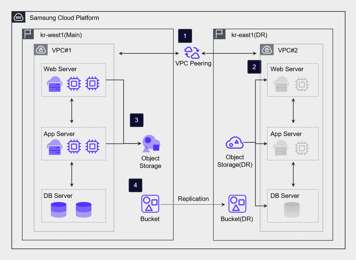
Connect kr-west1 Region (primary center) and kr-east1 Region (DR center) via VPC Peering.
Create a DR Virtual Server in the kr-east1 Region (DR center) and keep it powered off during normal operation.
Periodically back up the Virtual Server data in the kr-west1 Region (main center) to Object Storage.
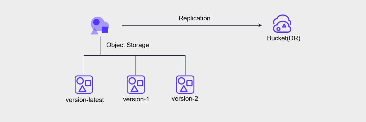
Using the DR synchronization feature in the Object Storage of the kr-west1 Region (primary center), we perform bucket-level asynchronous replication to the Object Storage (DR) of the kr-east1 Region (DR center).
In the event of a disaster, we recover the data in the Object Storage (DR) within the kr-east1 Region (DR center) and resume the service.
Warm Level
The Warm Level approach builds the DR center around systems with high service importance.
Because real-time replication between the primary center and the DR center does not occur, a periodic synchronization process is required.
In the event of a disaster, resources from the remaining systems are allocated and expanded before restoring the service, which can lead to data loss and may require a considerable amount of time to recover the service.
However, it has the advantage of relatively lower initial investment and maintenance costs compared to the Hot Site approach.
Hot Level
The Hot Level method builds the system in an Active-Standby state based on real-time replication.
This method is suitable for high‑priority systems because, in the event of a disaster, it stops replication and switches operations to the DR center, allowing services to be resumed quickly.
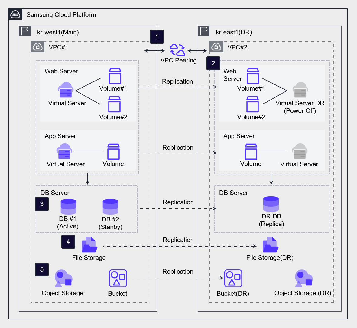
Connect the kr-west1 Region (primary center) and the kr-east1 Region (DR center) via VPC Peering.
For Virtual Servers intended for WEB/APP, create a DR Virtual Server in the kr-east1 Region (DR center) using the Virtual Server DR service. In disaster situations or during simulation drills, use the DR Virtual Server as the primary Virtual Server.
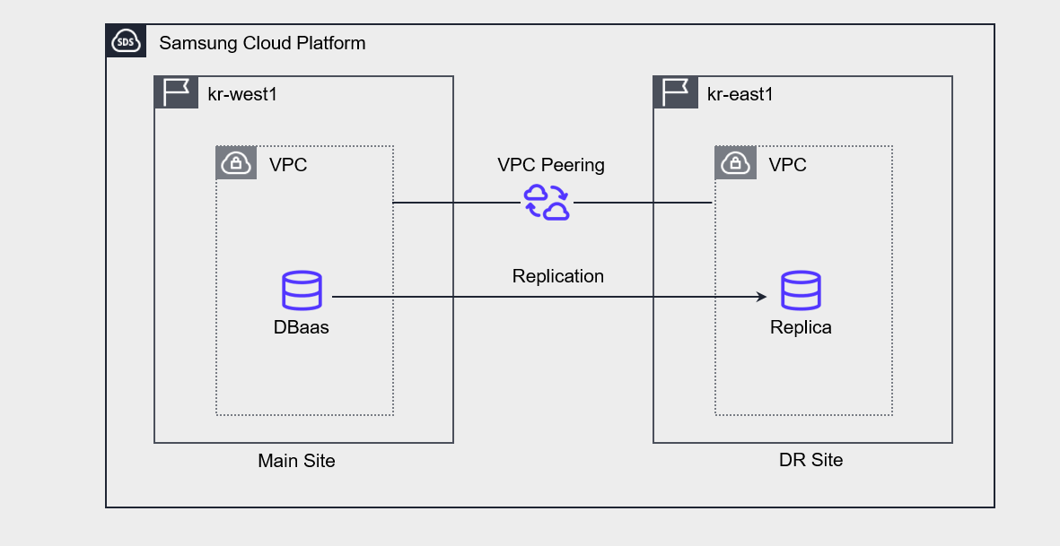
In the case of DBaaS, data is asynchronously replicated through a cross‑region replica configuration, and in a disaster scenario, the DR replica is promoted to master and used as the primary database.
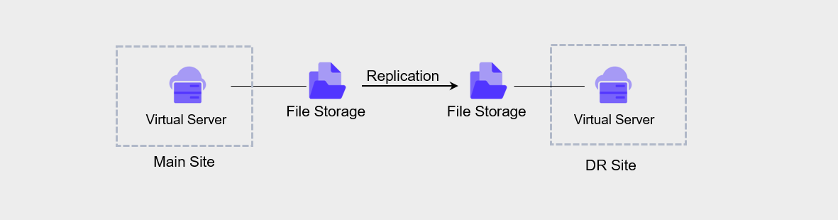
For File Storage, use the DR replication feature in the File Storage of the kr-west1 region (primary center) to set up a replicated volume in the kr-east1 region (DR center). After setting the replication interval and synchronization policy, the volume is replicated, and in a disaster situation, synchronization is halted and the replicated volume is switched to R/W mode for use.
In the case of Object Storage, we perform asynchronous bucket-level replication from the Object Storage in the kr-west1 region (primary center) to the Object Storage (DR) in the kr-east1 region (DR center) using the DR synchronization feature. In disaster situations, access and use the Object Storage (DR) bucket (DR) through its endpoint.
Data replication between regions for disaster recovery
Samsung Cloud Platform supports DR through various levels of storage replication.
Virtual Server DR
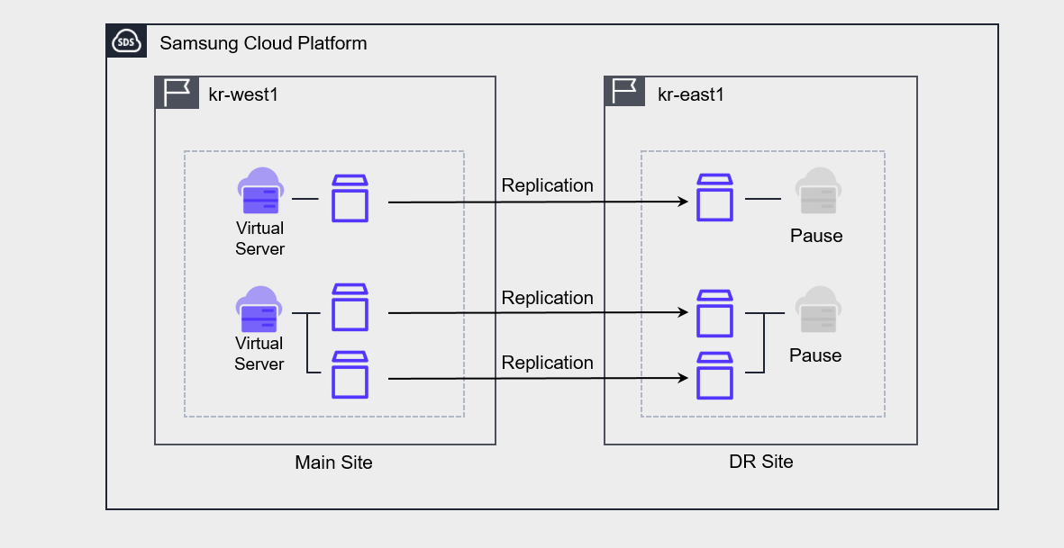
Virtual Server DR is a service that replicates Virtual Servers and their associated Block Storage to a Region different from the currently used Region, provides planning and testing for disaster preparedness, and offers recovery capabilities when an actual disaster occurs.
In fact, what is replicated is the Block Storage, and the Virtual Server at the DR site remains in a stopped state.
Backup DR
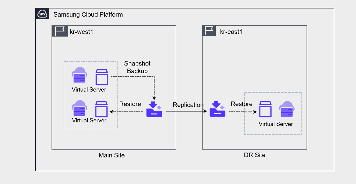
Backup DR is a feature that can be enabled when creating a service. When Backup DR is enabled, the backup performed on the primary site is replicated and stored on the DR site.
Object Storage DR
Object Storage DR is configured through synchronization settings between the primary site’s bucket and the DR site’s bucket. To set up DR, versioning must be enabled on the primary site’s bucket.
File Storage DR
File Storage DR can be configured from the primary site File Storage by setting the DR region, DR volume name, and replication schedule.
The replication interval can be selected from 5 minutes, 1 hour, daily, weekly, or monthly. Daily replication runs at 23:59:00, weekly replication runs on Sunday at 23:59:00, and monthly replication runs on the 1st at 23:59:00.
Database Service DR
In Database service DR, you can create a replica of the primary site master DB at the DR site and configure it.
When you configure a Replica, changes to the primary site are synchronized with and reflected in the Replica.
To configure a replica, a peering connection must be established between the primary site’s VPC and the DR site’s VPC.
In the event of a disaster, manually promote the replica at the DR site to master and bring it online.
Container Registry DR
When you use Container Registry DR, the DR registry and the Object Storage bucket are replicated to a different region.
Through this, you can replicate a Kubernetes cluster’s image from one region to another and create an identical Kubernetes cluster.
When configured together with File Storage DR, you can implement Kubernetes Cluster DR.
※ The cross‑region Container Registry feature is planned for release (‘26).
Develop a disaster transition plan
When a service interruption occurs, if it is determined—through assessment of the incident severity and the recoverable time window—that recovery cannot be achieved within the predefined timeframe, a disaster is declared and the disaster recovery procedures are carried out.
The steps of disaster recovery are as follows.
| Step | activity | Member responsibilities |
|---|---|---|
| Disaster declaration | Disaster status assessment |
|
| Disaster declaration | Disaster Recovery System Conversion Decision |
|
| Disaster recovery activities | Service transition to the disaster recovery center |
|
| Disaster recovery activities | Main Center Recovery |
|
| Main Center Recovery | Decision to return to the main center |
|
Service Change Management
Maintaining consistency between the primary site and the DR site
If updates, patches, and similar actions are performed on the primary site, the infrastructure, applications, and configuration of the DR environment may change.
As a result, the system may not operate correctly when performing disaster recovery.
Therefore, you should set up a test/staging environment to verify changes first, and then apply them to the primary site and DR site to improve deployment consistency and reliability.
- Do not make changes directly on the main site; instead, make changes through the test/staging environment.
- Utilize the deployment environment for software updates, security patches, infrastructure configuration changes, etc., and apply them to the primary site and DR site.
Change Management Through Automation
When service changes are performed manually, various variables can arise.
As a result, if there are configuration differences between the primary site and the DR site, the primary site’s functionality may not operate as intended on the DR site during disaster recovery.
Therefore, we must automate the deployment process to minimize the impact of such potential errors.
- Manage and deploy infrastructure templates using automation tools.
- Manage code in a secure central repository.
- We manage the process from development to deployment through continuous integration and continuous delivery (CI/CD).
Disaster/Failure Response Test
When a disaster occurs, establish procedures for switching to the DR site and returning to the primary center, and regularly verify that these procedures operate correctly.
During a simulation exercise, we assume fault or disaster scenarios to test the system and response procedures.
The key items to check in a disaster recovery drill are as follows.
- Whether the disaster recovery system restores data correctly
- Command and coordination system of the recovery team
- Internal/External communication status
- Performance of the disaster recovery system
- Main center return validation
- Notification procedures and other related matters
- Assuming a failure or disaster occurs, the team actually performs the required tasks, thereby enhancing response capability and identifying improvements.
- Execute the switchover procedures according to the disaster recovery plan and verify that the automatic switchover process operates correctly.
The disaster recovery drill plan must detail the schedule, organization and participants, the training scope and scenarios, and be written in detail down to the level of system commands.
Additionally, a checklist for each task, along with the relevant personnel and emergency contact network, must be specified.
The table below is an example of the disaster recovery training procedures and execution details.
| Order | Training method | Work performed | Responsible department |
|---|---|---|---|
| 1 | Preparation |
| Related work person in charge |
| 2 | Disaster Declaration |
| Emergency Response Team |
| 3 | Disaster Recovery System Operation |
| System, Network, responsible for |
| 4 | Work test |
| person in charge |
| 5 | Disaster Recovery System Transition to Live Operations |
| System, Network, responsibilities |
| 6 | Normal status Monitoring |
| system, network, person in charge |
| 7 | Disaster Recovery System Outage |
| system, network, person in charge |
| 8 | Return to work |
| System, Network, responsibilities |
| 9 | Result summary |
| Related work person in charge |