Availability Design
Architectural considerations for high availability
To implement a high‑availability architecture, it is necessary not only to design and build high availability at the infrastructure level using cloud services, but also to configure the application itself to support high availability.
Even if the underlying infrastructure such as servers and networks is built for high availability, to prevent service interruption when a single device fails, the application layer must also have a structure that can detect and respond to failures.
This is also true when you want to increase throughput via Auto-Scaling during a surge in demand.
The application must be designed to respond flexibly to scaling, enabling stable service expansion.
Simple Application configuration
A simple application reduces unexpected failures and enables stable operation.
Conversely, when many features accumulate in an application and its complexity increases, the likelihood of configuration errors or unforeseen interactions grows, leading to increased inefficiency.
A simple structure reduces the areas that need to be controlled, minimizing operational overhead.
This helps build a workload architecture that includes resilience (resilience), reusability (reusability), scalability (scalability), and manageability (manageability).
For this reason, each workload has various business requirements such as availability, scalability, data consistency, and disaster recovery, which become key criteria in architecture design.
For example, whether tens of thousands of users access the application simultaneously, whether traffic is steady or spikes at certain times, and whether service interruptions are permissible—and to what extent—are important considerations when designing the architecture.
Configuring the application in a more complex manner to handle workloads can provide additional functionality and flexibility.
However, this requires greater investment in coordination and communication management among components, which can actually have a negative impact on availability.
Therefore, if high availability is an essential requirement for the workload, it is advisable to reduce complexity as much as possible and minimize management points.
- Add the minimal components essential to the business requirements to the architecture.
- We configure an application optimized for the cloud environment using PaaS(Platform as a Service).
- Process simple repetitive calculations with minimal code using Serverless Computing.
To ensure high availability, it is important to implement the application with only the minimal essential components, reducing management points and enhancing scalability and repeatability.
Also, using PaaS instead of IaaS-based code is advisable because it can reduce the burden of infrastructure management and the complexity of configuring high availability.
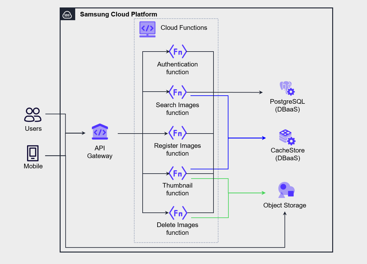
The architecture in the figure below is an example of implementing a mobile photo management service using Serverless Computing by leveraging API Gateway and Cloud Functions.
Implemented the Authentication, Search, Register, Thumbnail, and Delete functions as separate independent Cloud Functions.
When a user performs an operation in the mobile app, the request is passed to the function via API Gateway for processing.
In this architecture, all functions operate independently, so modifying one function does not affect the others.
After separating functions to achieve simplicity, it is important to ensure service observability through service monitoring.
In Cloud Functions, monitoring features are provided for call count, execution time, current task count, successful/failed call count, memory usage, etc., and you can also view function execution logs.
Application Decoupling and Dependency Management
To implement a high-availability Application, you must properly manage the dependencies of its components.
Managing component dependencies means identifying whether each component operates independently or has a dependency relationship with other elements, and carefully reviewing the availability of the dependent elements.
Ultimately, the key to implementing high availability is designing and managing systems so that a failure of a single component does not lead to a total service outage.
Therefore, the management approach for the component with the lowest availability among the interdependent components must be given top priority in high‑availability design and operation.
As a result, a service’s availability cannot exceed the level of the least available component among its dependencies.
- Maintains a list of all dependencies.
- Minimize critical dependency items to reduce the likelihood that a failure of a single component will affect the entire system.
- Important dependencies are configured redundantly.
- Use a Load Balancer or asynchronous messaging to decouple requests and responses (decoupling).
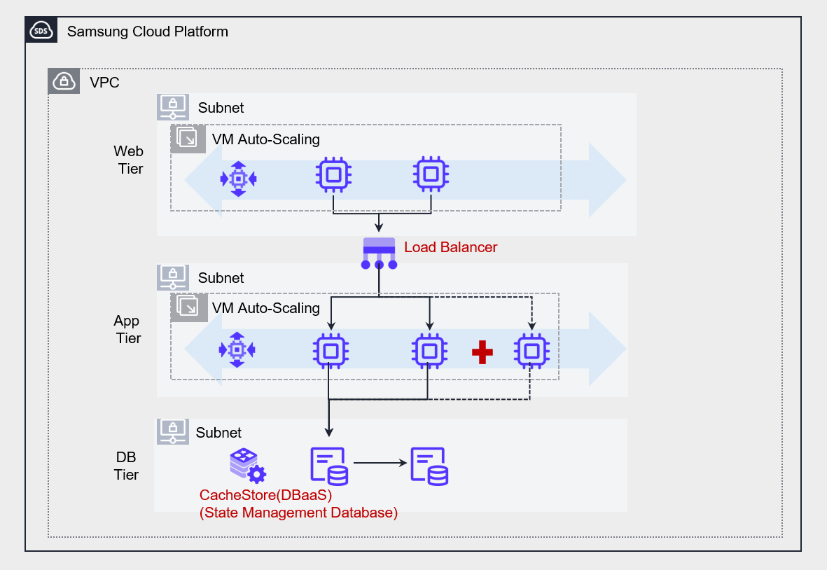
The figure below shows an example architecture that decouples the web and application layers using a Load Balancer.
If the web server and application server are directly connected, the dependency between components increases, making it difficult to implement scalability features such as auto-scaling.
Accordingly, by placing a Load Balancer in the middle, we reduced the dependency between the web and the application and improved the overall system scalability.
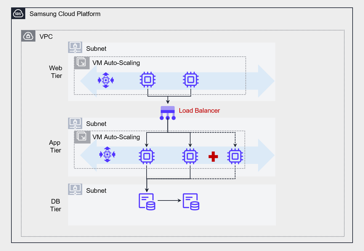
If there is no Load Balancer between the web layer and the Application layer, the web layer must directly specify the Application layer’s server IP address to forward requests.
This approach causes strong coupling between servers, and if one of the Application layer servers goes down, requests directed to that server cannot be processed and will inevitably be lost.
This may be perceived as a service disruption by some users and can degrade the overall system stability.
Conversely, placing a Load Balancer between the web tier and the application tier provides a single entry point for handling client requests, allowing requests to be routed flexibly without hard‑coding server IPs.
In particular, when the Auto-Scaling feature is applied to the Application layer, it can automatically distribute requests to server instances that are dynamically created or terminated, thereby ensuring the system’s scalability and resilience.
Thus, the Load Balancer is suitable for real-time request processing based on synchronous (Synchronous) communication, and it contributes to achieving high availability by distributing traffic among multiple servers that perform the same function.
For example, you can effectively use a Load Balancer placed in front of the Web server group and the App server group to distribute traffic among the servers within each group.
However, if you want to achieve stronger decoupling between services, using a Message Queue Service is more suitable.
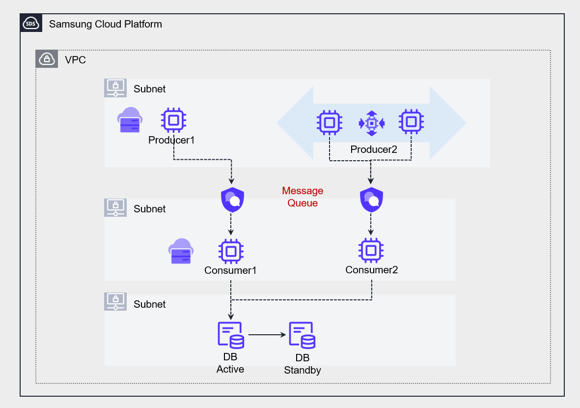
The figure below shows an architecture that uses a Message Queue to transform the strong coupling between two applications into a loosely coupled structure.
Message Queue Service enables asynchronous communication between multiple servers that perform different functions.
At this point, the processing speed or capacity of the producer (Producer) and consumer (Consumer) does not have to match.
As a result, each service can operate independently, and even if temporary failures or delays occur, they do not affect the entire system.
Additionally, because messages are safely stored in the queue, they can be processed when the consumer is ready, ultimately enabling the implementation of a resilient system architecture.
Stateless Application Development
State refers to internal service information that influences the processing of responses to client requests.
To be more precise, the values of variables or data structures that constitute the state depend on the history of requests processed by the service.
Stateful Application uses various dependencies, such as locally cached data, to perform tasks.
As a result, this cache data and its dependencies are loaded into memory, increasing server resource usage.
However, if the rate of incoming requests exceeds the server’s processing speed, the server will gradually slow down and may eventually stop functioning.
To resolve this, you can add new servers using Auto-Scaling.
However, if request tasks have already accumulated on the existing server, adding a new server may not deliver the expected performance improvement.
- Implement the application as stateless (Stateless).
- Implement a state management database (State Management Database) outside the service.
Stateless Application does not store information locally but stores it in an external state management database (State Management Database) to process tasks.
When a user request arrives, first store the request in the state management database, and when the CPU processes the request, read the request from the state management database and handle it.
In this architecture, the server does not store state and runs only to handle requests.
When a new server is added to the server pool, it can immediately read and process requests from the state management database.
This approach quickly distributes the workload across all servers, enabling effective implementation of high availability and scalability.
For state management databases, we mainly use NoSQL that supports fast read/write. In particular, for applications that require high performance, we recommend using CacheStore (DBaaS).
Cloud architecture design for high availability
Network design for scalability and availability
Network Design Considering Failure Occurrence For users to connect to the service reliably, not only must the server operate stably, but the network connecting to the server must also be managed reliably. Even if a failure occurs in some network segments of the service path, you should either select a service that inherently supports redundancy to prevent service interruption, or duplicate the network connections yourself to prepare for failures.
Network Design Considering Demand Growth All cloud services have certain limits on the resources that users can configure. For example, in Samsung Cloud Platform, you can create up to 5 VPCs per Account, and each VPC can be configured with up to 3 subnets. We must thoroughly review these constraints to ensure that capacity limits do not become a hindrance when scaling resources in response to future demand growth. Therefore, during the initial network design phase, you must carefully consider how to place the system within a scope (such as Account, VPC, subnet, etc.). If the service has a wide geographic scope, you should consider a Global CDN. If the service’s users are distributed across a wide geographic area, it is necessary to configure a Global CDN to reduce content delivery latency and provide an improved user experience.
Network design considering connections with other information systems and networks When connecting to information systems in other networks, you must carefully consider whether to route through a public network or establish a protected connection via a private network. If you want to connect via a private network to protect transmission, ensure that the private IP address ranges used in both networks do not overlap. When setting the private IP address for a newly configured system, you should check the existing network’s IP range and design the address range to avoid any overlap. Also, you need to consider the network topology based on the number of points where you will configure private connections. Private connections become more expensive as the number of connection points increases, and the complexity of network control policies and routing also rises. Therefore, to reduce this complexity, it is advisable to establish a centralized hub-and-spoke connection structure.
- To prepare for failures, configure redundant network connections or choose a network that supports high availability.
- Design a network suitable for current and future information systems, taking into account the limited capacity of cloud services.
- When connecting to other information systems, design to avoid overlapping IP address ranges, and preferably configure a hub-and-spoke topology.
For organizations that have multiple VPCs, an IP address plan must be established at the VPC level to design the overall network architecture.
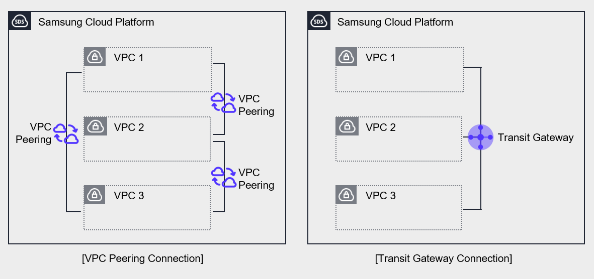
The figure above shows the network on the Samsung Cloud Platform composed of multiple VPCs.
Both the left and right sides have three VPCs configured on the Samsung Cloud Platform, and in both cases the connections are set up to allow private communication between the VPCs.
The left side uses VPC Peering to establish the VPC connection.
Since VPC Peering supports 1:1 connections, three connections must be established to link all VPCs.
In contrast, Transit Gateway enables you to manage multiple VPCs as a single configuration.
Connect three VPCs to a single Transit Gateway and configure routing between the three VPCs.
The Transit Gateway on the right centralizes network connections, simplifying connections and making them easy to manage.
Use managed service
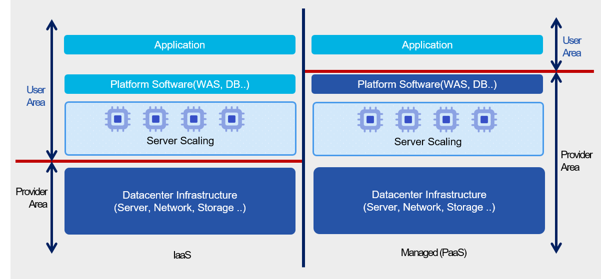
Managed Service (Managed Service) is a service provided on top of the infrastructure that the cloud provider operates and manages.
The areas managed by the cloud provider include the underlying server operating system and security, storage, and network.
Users can focus solely on the Application features provided by the service without the burden of installing and operating the underlying infrastructure.
Because it is managed by the cloud provider, services can be delivered reliably, and design and operation for high availability are implemented.
Therefore, by using a managed service, users can reduce the design and operational burden of high availability for that component.
Cloud Functions, a serverless computing service, is a prime example of a managed service; when handling simple repetitive tasks, using it instead of a virtual server can effectively achieve high availability.
Through this, users can minimize the likelihood of failures without additional design or management burdens and respond flexibly to increasing demand.
For databases, assume that two or more servers are created for MySQL high availability and that the operating system’s basic patches are applied.
After installing MySQL on each server, configure HA (High Availability) or a replica using InnoDB Cluster.
In this process, you must perform various tasks separately, such as configuring the network between servers, setting up security for data protection, and configuring backups, all of which belong to the implementation phase.
Continuous management tasks are required during the operational phase as well.
If you use the managed service MySQL (DBaaS), you can significantly simplify this process.
When configuring a database, you can automate high‑availability setup simply by adjusting options, and you can also achieve high flexibility and efficiency from an operational perspective.
- Simple repetitive tasks are implemented using Cloud Functions to realize serverless computing.
- Implement high availability using the Database service.
Microservice Architecture Implementation
Monolithic Architecture and Microservice Architecture
A monolithic application refers to a single-tier software application in which multiple modules are combined into a single program.
The figure below is an example architecture of an e-commerce application.
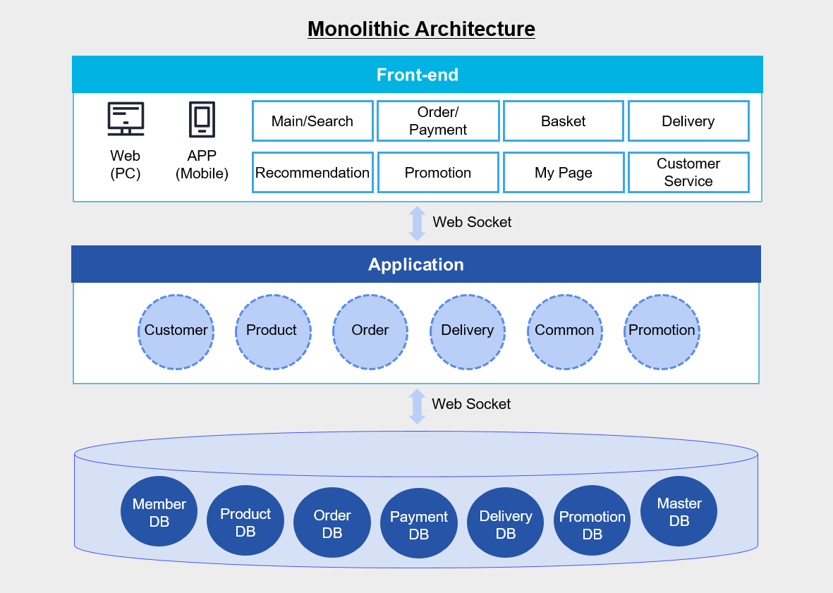
In the figure above, the Application integrates various modules such as customers, products, and orders into a single unit, and the database also shows that member DB, product DB, and order DB are configured on a single DB server.
By developing as a monolithic Application like this, you can easily deploy the Application simply by copying the packaged Application to the server.
Since all modules share resources such as CPU, memory, and disk, there is an advantage of being able to manage functions like logging, caching, and security in a single solution.
Additionally, because calls between modules occur within the same server, it is also advantageous in terms of performance.
However, as the application grows and becomes more complex over time, managing changes becomes difficult, deployment becomes more complicated than initially, and operational burden increases.
In particular, errors or changes in a single module are likely to cause a total system failure.
Consequently, a significant amount of time and cost is inevitably required for management and testing.
In contrast, a Microservice architecture consists of small unit Applications with their own architecture and business logic, each independently implementing a single function or a set of functions.
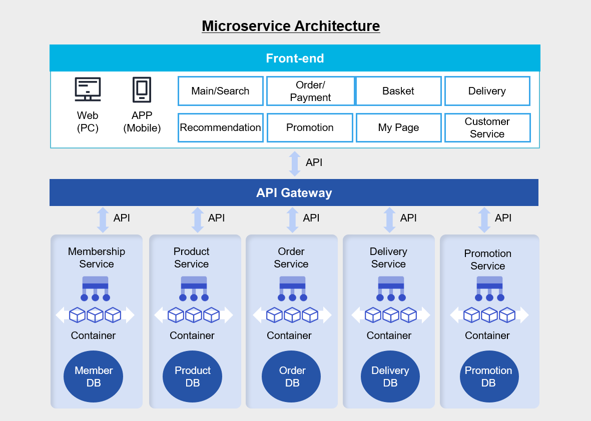
In a monolithic architecture, each business logic module resides on a single application server, and multiple databases are consolidated onto a single database server.
And the web, application, and database are connected via socket communication.
In contrast, in the Microservice architecture above, the business logic and database are organized independently for each business logic, and they connect to the frontend via APIs.
If you develop the application by separating it into multiple manageable units, the development speed of each feature increases and the overall architecture becomes easier to manage.
Since the features are independently structured, you don’t need to develop all of them in the same language, and they are not impacted by changes to other features’ frameworks.
Therefore, it is easy to improve each feature’s code and logic individually.
Additionally, because functions can be operated in isolation from each other, the impact of failures or overloads in other functions can be excluded or minimized.
However, because communication between each function must occur via API, a separate inter-service communication mechanism must be implemented.
Additionally, because the service flow spans multiple functions and each function initiates a database transaction, it can be difficult to track state when a call fails or is delayed.
Above all, as the number of independent components increases, each element must be managed individually, which inevitably raises operational burden.
Microservice Architecture Suitability Review
To determine whether applying a microservice architecture is suitable for the application you want to build, consider the following points.
- Can a business domain be divided into multiple independent subdomains (based on the core principles of Domain-driven design (DDD))?
- Can the development/operations organization be divided into multiple teams, with each team responsible for a “service unit”? (DevOps) and as part of the core principles of a microservices architecture (MSA) strategy.
- Is there a clearly defined stable domain that requires a high availability (HA) strategy for predicting partial traffic hotspots?
- Does each service (or microservice) within the organization have its own rate of change, release cycle, and requirements?
- Can the operational automation framework (CI/CD, monitoring, logging, tracing, etc.) be applied to improve operational maturity and strengthen incident response?
- Are you taking into account the strategic goal of pursuing long-term growth for the organization and product, and independent development by domain?
Microservice Architecture implementation example
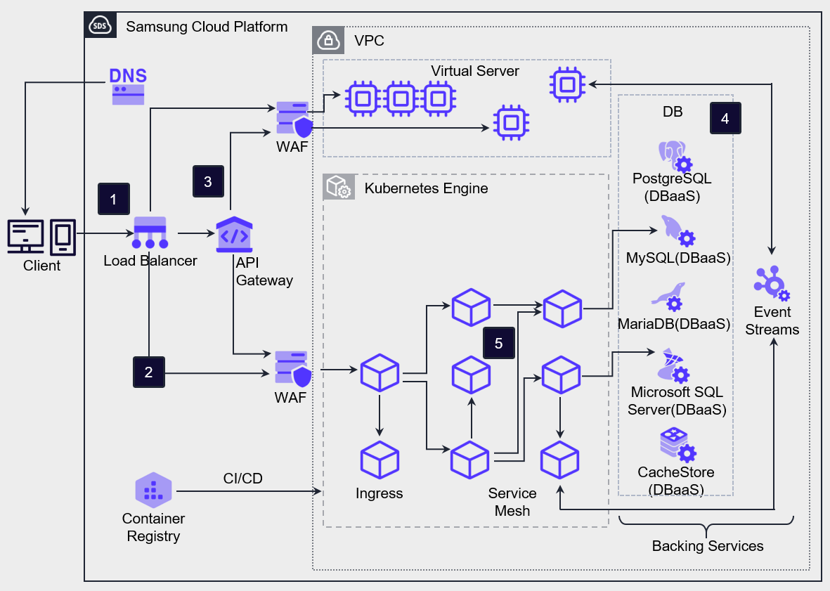
Client requests are delivered to VM/Container workloads and the API Gateway service via the Load Balancer.
Client requests, except for API requests, are forwarded to the ingress provided by Kubernetes Engine, and Kubernetes Engine routes the incoming requests through the ingress to the mapped service Pods.
To handle client API requests, the API Gateway is positioned at the frontmost layer and performs authentication and service routing for all incoming API calls from external sources.
Microservice Architecture consists of databases separated into structured service units.
You can use Service Mesh technology to control the network between microservice components, enabling management and tracing of various network configurations and data flows among segmented applications.
If you configure separate data stores for each service, you gain the flexibility to select the database that best matches that service’s characteristics.
For example, a web traffic management service that requires scalability can leverage highly scalable NoSQL, while an order processing service can use a relational database (RDBMS) to ensure data integrity and transaction consistency.
Additionally, by configuring a separate build system for each service, you can more easily apply changes per service and create an environment that enables rapid deployment of new features.
This approach has the advantage of quickly improving the quality of individual services without affecting other services by improving only the necessary code.
By using APIs for inter-service communication, you can manage services by domain and route requests appropriately.
In particular, by adopting an API Gateway, you can centrally manage and deploy service contracts, and you can also receive a feature that limits requests to a certain level (Throttling) when excessive requests occur.
When you configure an application in the container environment of Kubernetes Engine, you can achieve faster deployment and flexible scaling.
You can set limits on CPU and memory usage for each container, preventing a specific service from consuming excessive resources.
Additionally, in Kubernetes, the Probe feature continuously verifies a container’s proper operation and can automatically restart it if a problem occurs, helping to mitigate errors.
In a Serverless Computing environment, you can build an architecture that handles simple, repetitive tasks in an event-driven manner by leveraging Cloud Functions.
Additionally, by storing web content in Object Storage, you can distribute the load from web content requests across servers, enabling efficient resource management.
Adjusted according to demand
Service availability issues are not limited to cases where the service stops due to a component failure. When unexpected external factors increase request load, the operating server can reach its capacity limit, causing service interruption, which is also a significant factor affecting usability.
In on-premises environments, responding to such overload situations requires extensive preparation and meticulous management, whereas cloud environments provide infrastructure that can respond to demand fluctuations quickly and flexibly.
- Implement server scaling (expansion and reduction) by managing Virtual Server images.
- Use a managed service that imposes little or no burden for managing infrastructure resource capacity.
Virtual Server can be vertically scaled (Scale-up) by increasing the specifications of the server type according to demand, and you can horizontally scale out (Scale-out) by registering a server created from an Image with a Load Balancer, or horizontally scale in (Scale-in) by deleting a server.
When using Auto-Scaling, you can automatically scale the number of servers horizontally—expanding or shrinking—according to the configured policy without manual intervention.
By using managed services, the cloud provider directly manages scaling and shrinking of the infrastructure, enabling flexible architecture design.
Serverless computing such as Cloud Functions can be configured for event-driven computing without restrictions on the underlying infrastructure, and by using services like Object Storage, you can build data stores without capacity limits.
Although the Database service cannot scale the number of servers according to demand, you can easily scale the database server specifications vertically, and improve read performance through replicas.
Resource Adjustment Automation
The cloud provides useful tools to flexibly respond to changes in demand, and Auto-Scaling is a representative service that supports automatic resource adjustment based on demand fluctuations.
Elasticity (Elasticity) is the capability to flexibly adjust resources according to demand by providing additional physical resources when service demand increases, and reclaiming resources when there is excess capacity.
Resilience is activated through automated operation based on specific metrics.
In Samsung Cloud Platform, Auto-Scaling works on Virtual Server and Container.
- Implement metric-based Auto-Scaling to achieve horizontal scaling and downsizing of Virtual Server.
- Enable automatic scaling of the Kubernetes Engine Node Pool to implement automatic resource scaling.
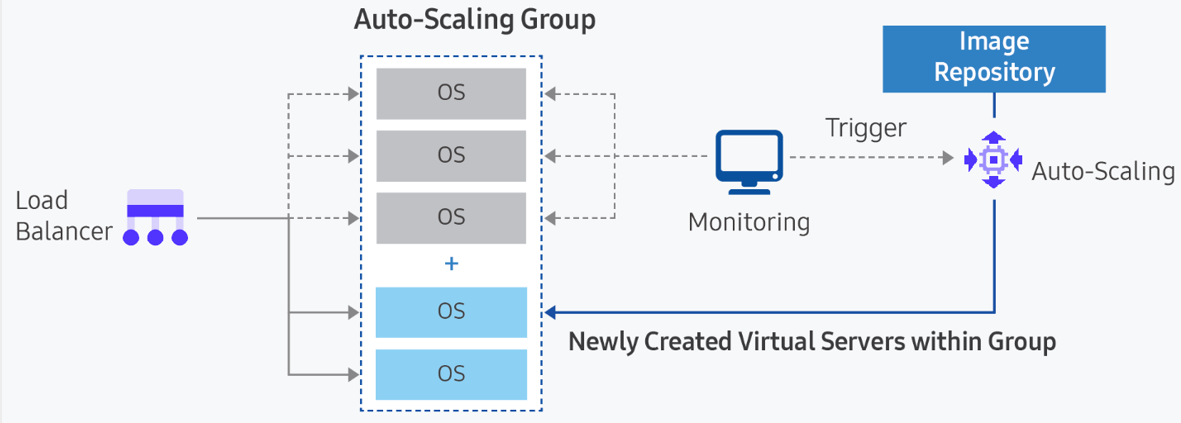
- Auto-Scaling Auto-Scaling is a computing service that automatically creates or deletes VMs based on resource usage, according to predefined conditions or schedules. Through this, users can maintain stable services and operate servers efficiently. Register VMs as a server group in the Load Balancer to distribute request load to each VM. According to the predefined policy, we either create and add new VMs or delete existing VMs. The metrics that can be configured in a policy include CPU, memory, disk usage, and network traffic.
- Container Since containers run on a runtime engine hosted on a VM, automatically scaling containers requires two decisions. First, you need to determine whether an additional container is required for the current workload. Second, you need to determine whether a new container can be allocated to a node in the existing node pool or must be allocated to a new node. To have new nodes allocated automatically, you must use the node pool auto-scaling option when creating a node pool in Kubernetes Engine.
Managing bottlenecks that limit scalability
To apply Auto-Scaling for automatic response to increased demand in the service architecture, you must first identify resources that could become bottlenecks due to the service’s capacity limits.
- Identify points in the service flow where expansion is not possible.
- Consider alternatives that can handle the increased demand during expansion.
There are also applications that scale vertically by adding CPU cores, memory, or network bandwidth to a single VM instance to handle increased load.
These applications have strictly limited scalability, so they often need to be manually configured to handle increased load.
For example, relational databases cannot be horizontally scaled.
Even if the database service implements redundancy, it supports Active–Standby, so horizontal scaling cannot be implemented.
In this case, you can consider vertical scaling by increasing the CPU and memory specifications while accounting for maximum capacity in advance, and you can also consider offloading read load through replicas or caching.
Gradual level degradation and load mitigation design during load spikes
Even if load spikes and the server becomes overloaded, it must be designed to prevent service interruption.
You must control traffic to ensure that, even if low‑quality responses are returned to users, the service does not completely stop.
Also, it must be designed so that the service can operate even under overload conditions.
When the service detects overload, it should return low‑quality responses to users, or partially throttle or drop traffic to prevent the entire service from completely stopping due to overload.
- Configure a connection queue using a high-volume access control solution.
- Configure a static web page to temporarily respond to user requests.
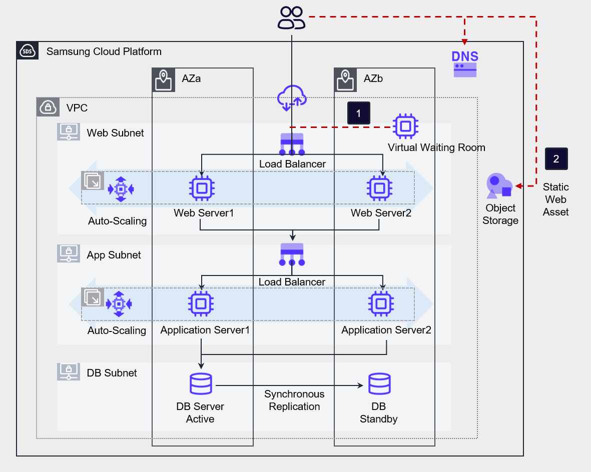
Use third‑party solutions such as a large‑scale access control solution (Virtual Waiting Room) to create a user queue, enabling the load from massive connections to be handled gradually.
You can also store static web assets in Object Storage to reduce the load on the web server.
Component design for failure response
Resource Redundancy and Multi-AZ Configuration
A highly reliable system must have no single points of failure. To achieve this, resources should be configured redundantly to prevent such failures in advance.
By utilizing the built-in fault avoidance options of the service, we prevent service interruptions caused by physical failures, and through redundant resource deployment, we enable other resources to handle tasks when a failure occurs in one resource.
Deploy workload data and resources across multiple AZs so that the service remains uninterrupted even if a failure occurs in a specific availability zone.
Additionally, to avoid a Single Point of Failure at the physical infrastructure level, resources are redundantly deployed across Multi-AZ.
- The Virtual Server is redundantly deployed together with the Load Balancer. If the requirements permit, configure Auto-Scaling to implement automated redundancy.
- Apply Anti-Affinity to the server group to prevent the Virtual Server from experiencing service interruption due to host failures.
- Deploy resources across multiple AZs to handle Single-AZ failures.
- Configure the database redundantly using the Database service’s high availability (HA) and replication (Replica).
The AZs in Multi-AZ are built on independent physical infrastructure and are designed to be unaffected by failures in other availability zones.
Therefore, even if a failure occurs, it only affects the affected AZ and does not impact other AZs.
When you select Multi-AZ to deploy resources, you can prepare for various disasters.
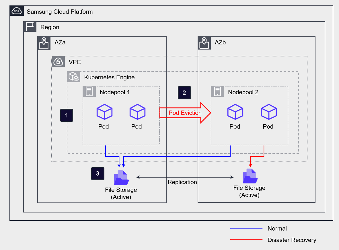
If you configure File Storage as Multi-AZ, the primary and replica are created in separate AZs, and the data between the primary and replica is synchronized in real time.
Configure the Kubernetes Engine and create a separate node pool in each AZ.
In normal operation, we use AZa’s Active Storage on all nodes and Pods.
If a disaster occurs in AZa, the Pod running in AZa is evicted to the AZb node, and the storage access path is switched to the AZb Standby Storage.
Even if you must deploy on a single server, you should design it so that a failure of that server does not cause a total service outage.
To implement a high‑availability service, it is essential to implement the components that constitute the main flow of the service using redundancy or multi‑instance approaches.
Due to specific constraints, applications that run on a single server must be deployed so that a server failure does not affect the service’s primary workflow.
The figure below is an example of a three-tier Application.
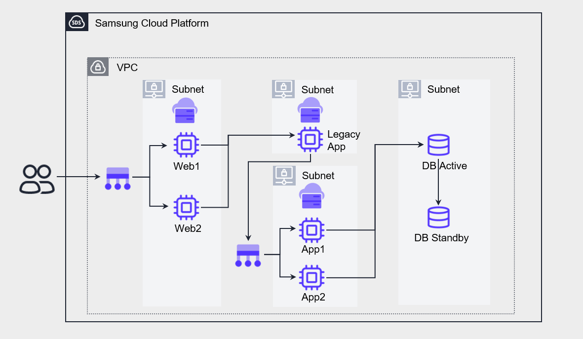
This application has a service flow composed of Web - Legacy App – App – DB.
Web, App, and DB are configured with high‑availability redundancy, but the Legacy App can only be deployed on a single server due to specific constraints (inability to modify source code for redundancy, software license restrictions, etc.).
In such cases, a failure on the Legacy App server will cause the entire service to stop.
As a result, that server becomes a single point of failure, reducing the overall service availability.
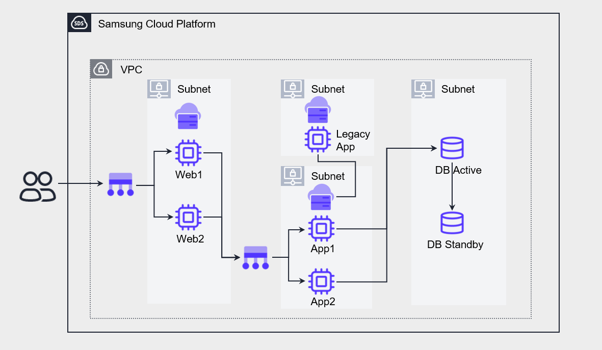
The architecture above separates the Legacy App from the primary flow and is designed to be referenced by the App.
When configured this way, even if the Legacy App server experiences a failure, only certain functions are limited, and the overall service is affected minimally.
Normal resource creation for incident response
Configure a mechanism that can recover resources when a failure occurs, using the inherent capabilities of cloud resources or automatic recovery configurations.
- Recover abnormal resources using Auto-Scaling.
- Enable the node auto-recovery feature in Kubernetes Engine to respond to failures.
If the minimum number of instances for Auto-Scaling is set to 2, when a VM is removed from service due to a failure, the Load Balancer detects it, and the Auto-Scaling group automatically creates a new VM instance to maintain the minimum count.
By using this method, you can configure automatic fault response for Virtual Servers.
For containers, if you enable the node auto-repair feature in the Node Pool of Kubernetes Engine, automatic recovery is performed when a node experiences a failure.
Recovery is initiated when a node continuously reports a NotReady state for a certain period (threshold about 10 minutes) or fails to report its state at all.
However, if the initial node creation does not reach the Running state and remains in the Creating state, or if four or more abnormal nodes occur in the same node pool, automatic recovery may be limited.
Protect the service from malicious attacks
Various measures can be taken to prevent service interruptions caused by security breaches.
- Automatically respond to security attacks using managed security services.
- Automatically respond to denial-of-service attacks via Auto-Scaling.
- Establish a rapid response system through security event notifications.
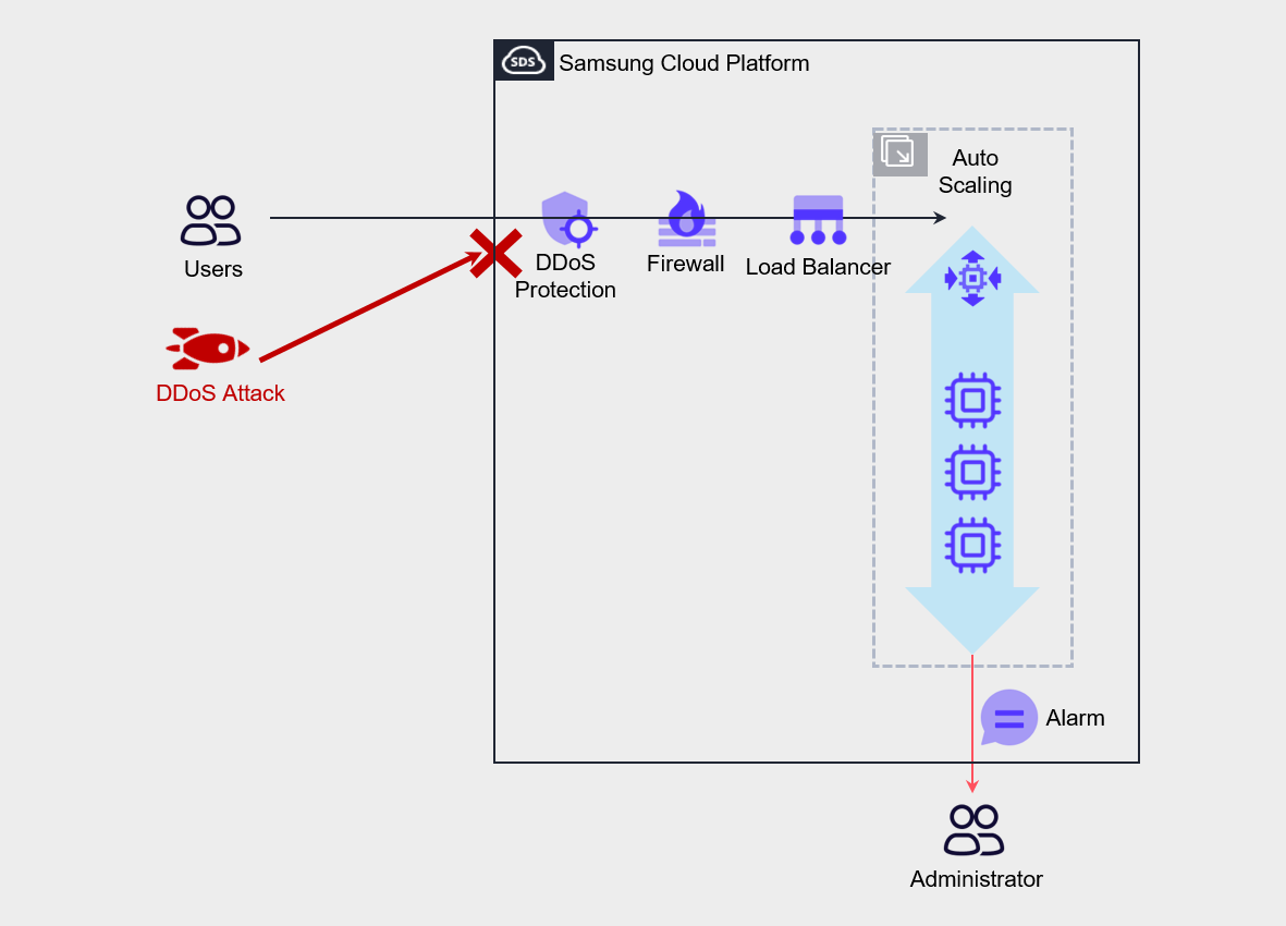
DDoS Protection, WAF, etc. serve to mitigate security attacks and are security services managed by Samsung Cloud Platform rather than directly by the user.
This enables rapid response to malicious attacks.
For service denial attacks such as DDoS attacks, configure Auto-Scaling to ensure the service can continue.
Additionally, you can configure admin alerts to block abnormal traffic on the firewall.